

Page 1

© Baxi Heating UK Limited 2005
Baxi Combi 133 HE Plus
Baxi Combi 100 HE Plus
Baxi Combi 80 HE Plus
Gas Fired Wall Mounted Condensing
Combination Boiler
These instructions include the Benchmark Commissioning Checklist
and should be left with the user for safe keeping.
Installation & Servicing Instructions
Page 2

2
© Baxi Heating UK Limited 2005
Natural Gas
Baxi Combi 133 HE Plus
G.C.No47 075 14
Baxi Combi 100 HE Plus
G.C.No47 075 15
Baxi Combi 80 HE Plus
G.C.No47 075 16
Baxi is a BS-EN ISO 9001
Accredited Company
This product has an energy rating (A) on a scale of A to G.
For more information see www.boilers.org.uk. This is a certification mark.
Building Regulations and the Benchmark
Commissioning Checklist
Building Regulations (England & Wales) require notification of
the installation of a heating appliance to the relevant Local
Authority Building Control Department. From 1 April 2005 this
can be achieved via a Competent Persons Self Certification
Scheme as an option to notifying the Local Authority directly.
Similar arrangements will follow for Scotland and will apply in
Northern Ireland from 1 January 2006.
CORGI operate a Self Certification Scheme for gas heating
appliances.
These arrangements represent a change from the situation
whereby compliance with Building Regulations was accepted as
being demonstrated by completion of the Benchmark Logbook
(which was then left on site with the customer).
With the introduction of Self Certification Schemes, the
Benchmark Logbook is being withdrawn. However, a similar
document in the form of a commissioning checklist and service
interval record is incorporated at the back of these instructions.
This company is a member of the Benchmark initiative and fully
supports the aims of the programme. Its aim is to improve the
standards of installation and commissioning of central heating
systems in the UK and to encourage the regular servicing of all
central heating systems to ensure safety and efficiency.
Building Regulations require that installations should comply
with manufacturer's instructions. It is therefore important that
the commissioning checklist is completed by the installer. The
relevant section of Building Regulations only relates to
dwellings. Therefore the checklist only applies if the appliance is
being installed in a dwelling or some related structure.
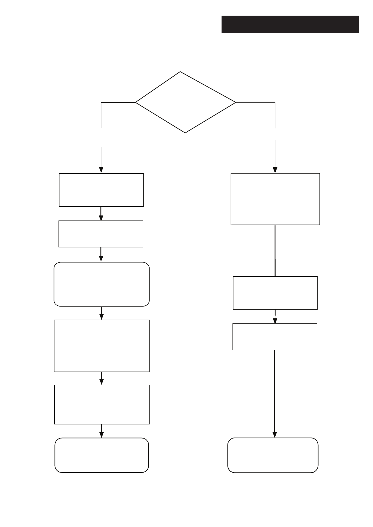
The flowchart opposite gives guidance for installers on the
process necessary to ensure compliance with Building
Regulations.
© Baxi Heating UK Limited 2005 All rights reserved. No part of this publication
may be reproduced or transmitted in any form or by any means, or stored in any
retrieval system of any nature (including in any database), in each case whether
electronic, mechanical, recording or otherwise, without the prior written
permission of the copyright owner, except for permitted fair dealing under
Copyrights, Designs and Patents Act 1988.
Applications for the copyright owner’s permission to reproduce or make other
use of any part of this publication should be made, giving details of the proposed
use, to the following address:
The Company Secretary, Baxi Heating UK Limited, Pentagon House,
Sir Frank Whittle Road, Derby, DE21 4XA.
Full acknowledgement of author and source must be given.
WARNING: Any person who does any unauthorised act in relation to a
copyright work may be liable to criminal prosecution and civil claims for damages.
The code of practice for the installation,
commissioning & servicing of central
heating systems.
“Baxi” supports
Page 3
Installer Notification Guidelines
3
© Baxi Heating UK Limited 2005
Choose Building
Regulations Notification
Route
Competent Person's
Self Certification Scheme
Install and Commission this
appliance to manufacturer's
instructions
Complete the
Benchmark Checklist
If you notify via CORGI Scheme,
CORGI will then notify the
relevant Local Authority
Building Control Scheme
on member's behalf
Building Control
Contact your relevant Local
Authority Building Control
(LABC) who will arrange
an inspection or contact
a government approved
inspector
Install and Commission this
appliance to manufacturer's
instructions
Scheme Members only
Call CORGI on: 0870 88 88 777
or log onto:
www.corgi-notify.com
within 10 days
You must ensure that the
notification number issued by
CORGI is written onto the
Benchmark Checklist
CORGI will record the data and
will send a certificate of
compliance to the property
Complete the
Benchmark Checklist
LABC will record the data
and will issue a
certificate of compliance
Page 4

Legislation
4
© Baxi Heating UK Limited 2005
Baxi declare that no substances harmful to health are
contained in the appliance or used during appliance
manufacture.
The appliance is suitable only for installation in GB and IE
and should be installed in accordance with the rules in
force, and only used in a suitably ventilated location.
In GB, the installation must be carried out by a CORGI
Registered Installer. It must be carried out in accordance
with the relevant requirements of the:
• Gas Safety (Installation & Use) Regulations.
• The appropriate Building Regulations either The Building
Regulations, The Building Regulations (Scotland), Building
Regulations (Northern Ireland).
• The Water Fittings Regulations or Water Byelaws in
Scotland.
• The Current I.E.E. Wiring Regulations.
Where no specific instructions are given, reference should
be made to the relevant British Standard Code of Practice.
In IE, the installation must be carried out by a competent
person and installed in accordance with the current edition
of I.S. 813 ‘Domestic Gas Installations’, the current Building
Regulations and reference should be made to the current
ETCI rules for electrical installation.
All systems must be thoroughly flushed and treated
with inhibitor (see section 6.1).
IMPORTANT - Installation, Commissioning, Service & Repair
This appliance must be installed in accordance with the manufacturer’s instructions and
the regulations in force. Read the instructions fully before installing or using the
appliance.
In GB, this must be carried out by a competent person as stated in the Gas Safety
(Installation & Use) Regulations.
Definition of competence: A person who works for a CORGI registered company and
holding current certificates in the relevant ACS modules, is deemed competent.
In IE, this must be carried out by a competent person as stated in I.S. 813 “Domestic
Gas Installations”.
Lifting - This product should be lifted and handled by two people. For recommended
hand holds see section 8.4. Stooping should be avoided and protective equipment
worn where necessary. Carrying & lifting equipment should be used as required, e.g.
when installing in a loft space.
The addition of anything that may interfere with the normal operation of the appliance
without express written permission from the manufacturer or his agent could invalidate
the appliance warranty. In GB this could also infringe the Gas Safety (Installation and
Use) Regulations.
Warning - Check the information on the data plate is compatible with local supply
conditions.
All CORGI registered installers carry a CORGI identification card and have a
registration number. You can check your installer is registered by telephoning
0870 4012300 or writing to:-
1 Elmwood,
Chineham Business Park,
Crockford Lane,
Basingstoke. RG24 8WG
or check online at www.corgi-gas-safety.com
Codes of Practice, most recent version should be used
In GB the following Codes of Practice apply:
Standard Scope
BS 6891 Gas Installation.
BS 5546 Installation of hot water supplies for domestic
purposes.
BS 5449 Forced circulation hot water systems.
BS 6798 Installation of gas fired hot water boilers.
BS 5440 Part 1 Flues.
BS 5440 Part 2 Ventilation.
BS 7074 Expansion vessels and ancillary equipment for
sealed water systems.
BS 7593 Treatment of water in domestic hot water
central heating systems.
In IE the following Codes of Practice apply:
Standard Scope
I.S. 813 Domestic Gas Installations.
The following BS standards give valuable additional information;
BS 5546 Installation of hot water supplies for domestic
purposes.
BS 5449 Forced circulation hot water systems.
BS 7074 Expansion vessels and ancillary equipment for
sealed water systems.
BS 7593 Treatment of water in domestic hot water
central heating systems.
The boiler meets the requirements of Statutory Instrument “ The
Boiler (Efficiency) Regulations 1993 N
o
3083” and is deemed to
meet the requirements of Directive 92/42/EEC on the energy
efficiency requirements for new hot water boilers fired with liquid
or gaseous fuels:-
Type test for purpose of Regulation 5 certified by:
Notified Body 0087.
Product/Production certified by:
Notified Body 0086.
Ref: 86-BL-647
For GB/IE only.
Page 5
5
© Baxi Heating UK Limited 2005
1.0 Introduction 6
2.0 General Layout 7
3.0 Appliance Operation 8
4.0 Technical Data 9
5.0 Dimensions and Fixings 12
6.0 System Details 13
7.0 Site Requirements 16
8.0 Installation 22
9.0 Electrical 29
10.0 Commissioning the Boiler 31
11.0 Fitting the Outer Case 35
12.0 Servicing the Boiler 36
13.0 Changing Components 38
14.0 Short Parts List 49
15.0 Fault Finding 50
16.0 Operational Flow Chart 60
Benchmark Checklist 62
Section Page
Contents
Page 6
This boiler is fitted with a flow switch interlock that
prevents it from firing when the heating demand is
satisfied.
1.1 Description
1. The Baxi Combi HE Plus Range are fully automatic gas
fired wall mounted condensing combination boilers. They
are room sealed and fan assisted, and will serve central
heating and mains fed domestic hot water.
2. The boiler is preset to give a maximum output of 23.9
kW (81,500 Btu/h) for central heating and (39.0 kW
(133,000 Btu/h) 133 model) (30.2 kW (102,000 Btu/h)
100 model) (23.9 kW (81,500 Btu/h) 80 model) for hot
water. In central heating mode the boiler will
automatically adjust down to (10.6 kW (36,000 Btu/h)
133 model) 9.1 kW (31,000 Btu/h) 100 & 80 models)
according to system load.
3. They are designed for use on Natural Gas (G20) only.
4. The boilers are suitable for use only on fully pumped
sealed heating systems. Priority is given to domestic hot
water.
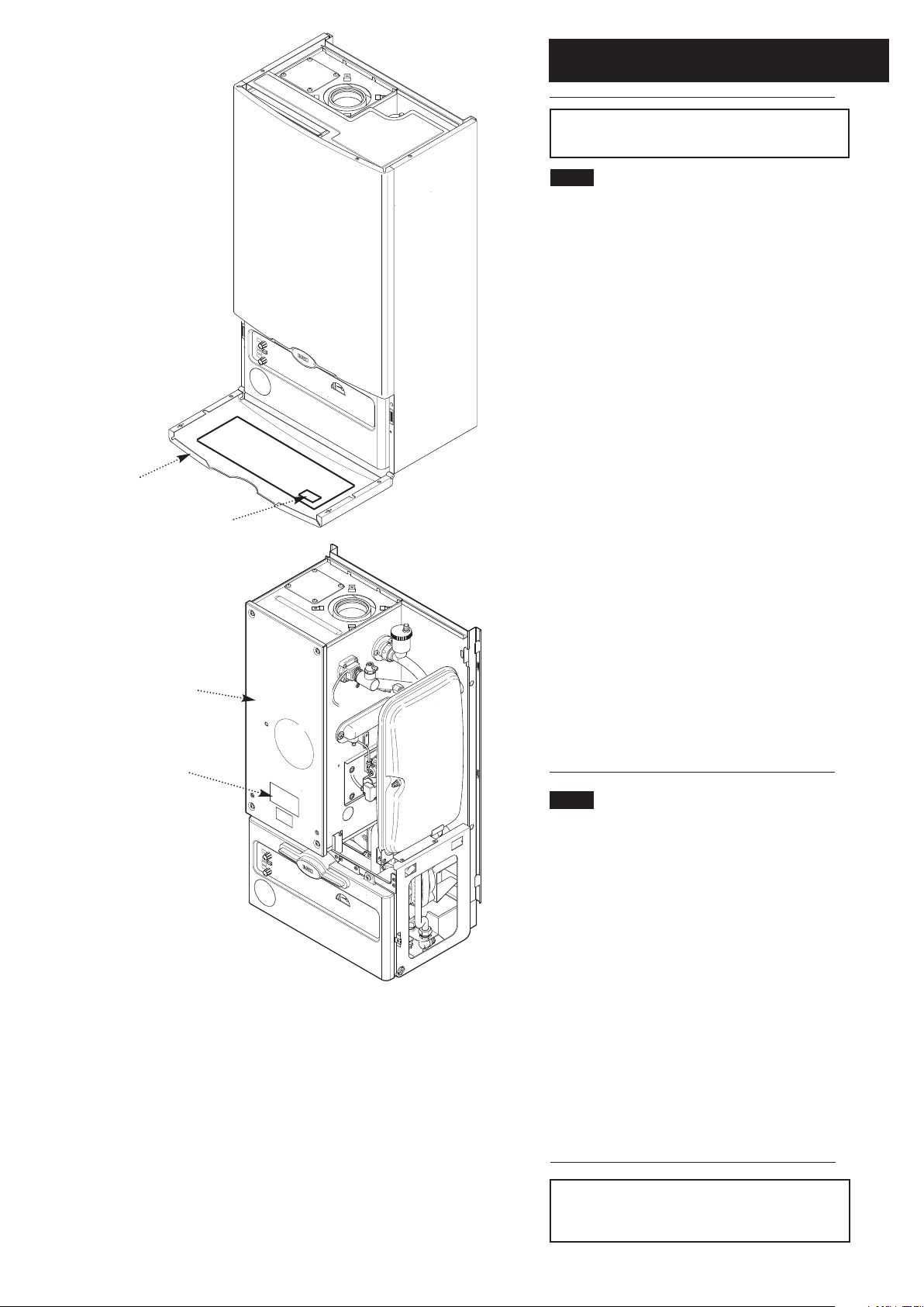
5. A label giving details of the model, serial number and
Gas Council number is situated on the rear of the lower
door panel (Fig. 1).
6. The boiler data badge is positioned on the air box
door (Fig. 2).
7. The boilers are intended to be installed in residential /
commercial / light industrial E.M.C. environments on a
governed meter supply only.
8. The boilers must be installed with one of the purpose
designed flues such as the standard horizontal flue kit,
part n
o
236921.
1.2 Important Information
Man-made mineral fibre
• Some component parts of this appliance (insulation
pads, gaskets and rope seals) are manufactured from
man-made mineral fibre.
• Prolonged or excessive exposure to this material may
result in some irritation to the eyes, skin or respiratory
tract.
• It is advisable to wear gloves when handling these
items.
• Irritant dust will only be released from the items if they
are broken up or subjected to severe abrasion. In these
instances a suitable dust mask and goggles should be
worn.
• Always thoroughly wash hands after installation,
servicing or changing components.
• When disposing of any items manufactured from manmade mineral fibre care must be exercised.
• If any irritation of the eyes or severe irritation of the
skin is experienced seek medical attention.
1.0 Introduction
6
© Baxi Heating UK Limited 2005
Fig. 1
Fig. 2
Lower Door Panel
Air Box Door
Data Badge
NOTE: All Illustrations show the Combi 133 HE Plus
unless otherwise stated. The PCB Connection Cover
is removed for clarity.
Label
Page 7
2.0 General Layout
7
© Baxi Heating UK Limited 2005
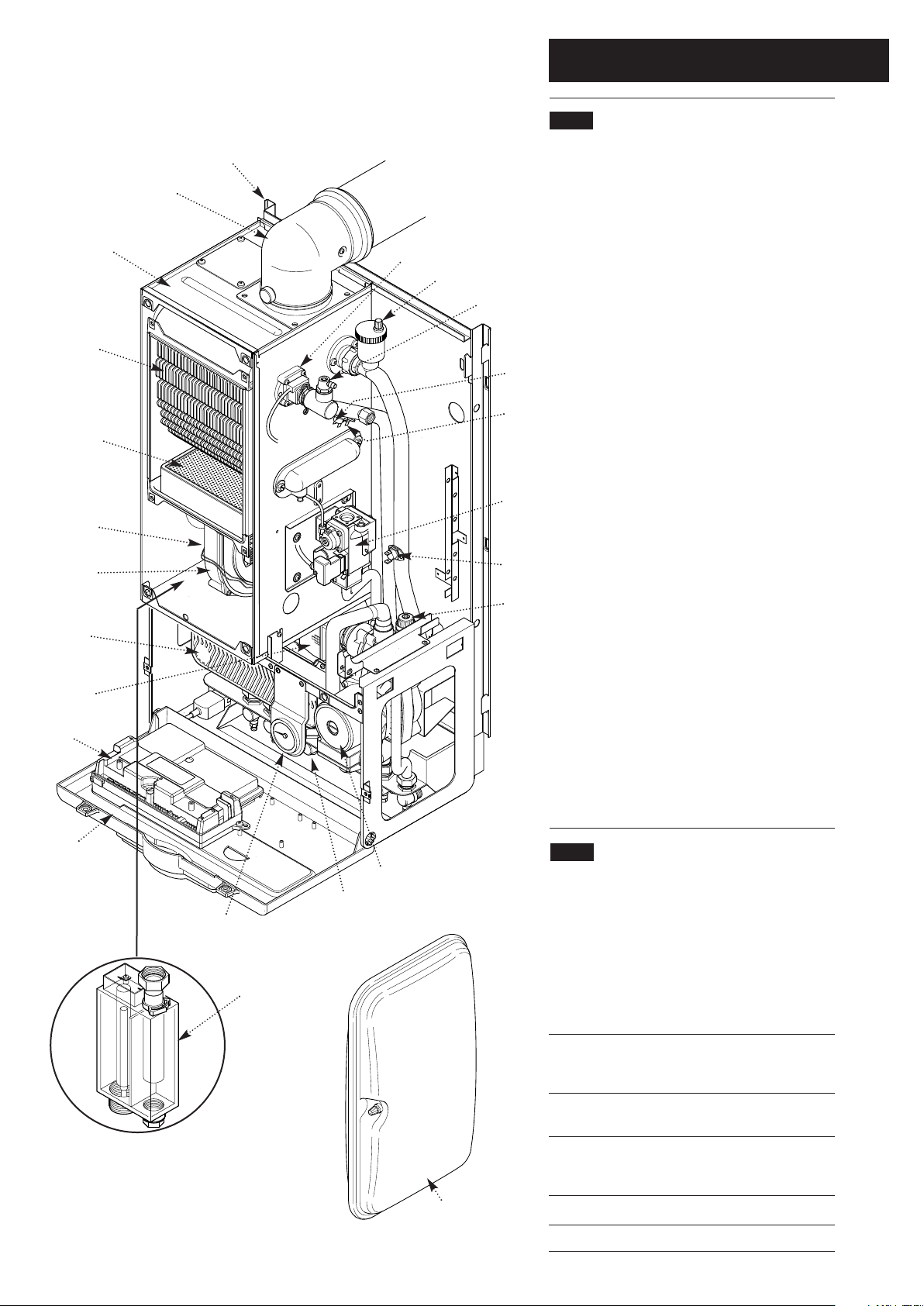
2.1 Layout
1. Wallplate
2. Flue Elbow
3. Air Box
4. Heat Exchanger
5. Burner
6. Fan Protection Thermostat
7. Fan Assembly
8. DHW Plate Heat Exchanger
9. Three Way Valve
10. Facia Box
11. Water Pressure Gauge
12. Gas Tap
13. Circulation Pump
14. Pressure Relief Valve
15. Return Thermistor
16. Gas/Air Ratio Valve
17. PCB
18. Flow Temperature Safety Thermostat
19. Flow Temperature Thermistor
20. Manual Air Vent
21. Automatic Air Vent
22. Flow Switch (Dry Fire Protection)
23. Condensate Trap
24. Expansion Vessel
2.2 Optional Extras
KIT PART N
o
FLUE EXTENSION KITS (110/70)
Horizontal Flue Kit 4M max
Flue Extension 0.25M 241692
Flue Extension 0.5M 241694
Flue Extension 1M
(Use two kits for 2M etc.) 241695
Flue Bend - 45°
(Reduce overall length of flue
by 0.5m when fitting this bend)
241689
Flue Bend - 90° (
Reduce overall length of flue
by 1m when fitting this bend)
241687
Horizontal Extended Flue (1.75M) 5111457
VERTICAL FLUE KITS (110/70) 5M max
Vertical Flue Terminal 242802
Vertical Boiler Connection 5106888
VERTICAL FLUE (80/80)
Kit Boiler Connection Twin 242757
CONTROL ACCESSORIES
RF Programmable Room Thermostat 5117204
Electro-Mechanical Timer 5117493
Filling Loop Kit 5111095
Plume Displacement Kit 5117383
1
2
4
5
3
6
7
23
12
16
10
22
13
21
20
14
11
24
8
9
15
Expansion Vessel
removed for clarity
18
19
17
Page 8
3.0 Appliance Operation
8
© Baxi Heating UK Limited 2005
NOTE: All delay timers mentioned in 3.1 and 3.2 are
overridden by domestic hot water demand.
3.1
Central Heating Mode
1. With a demand for heating, the pump circulates water
through the primary circuit. At a flow rate of
approximately 4.5 l/min the central heating flow switch
operates, initiating the ignition sequence.
2. The main burner ignites at a low rate, then the fan/gas
valve and proportionator control the gas rate to maintain
the heating temperature measured by the thermistor
sensor.
3. When the flow temperature exceeds the set
temperature, a 1 minute pump overrun occurs followed
by 3 minutes anticycle. If the flow temperature is low
enough the burner will then relight automatically
otherwise pump overrun and anticycle will occur again.
4. When the demand is satisfied the burner is
extinguished and the pump continues to run for a period
of 1 minute (Pump Overrun).
3.2 Domestic Hot Water Mode
1. Priority is given to the domestic hot water supply. A
demand at a tap or shower will override any central
heating requirement.
2. The flow of water will operate the DHW flow switch
and the 3-way valve will change position. This will allow
the pump to circulate the primary water through the
DHW plate heat exchanger.
3. The burner will light automatically and the temperature
of the domestic hot water is controlled by the return
thermistor.
4. When the domestic hot water demand ceases the
burner will extinguish and the diverter valve will remain in
the domestic hot water mode, unless there is a demand
for central heating.
3.3 Boiler Frost Protection
1. The boiler incorporates an integral frost protection
feature. It will operate in both summer and winter modes.
If the boiler temperature falls below 8°C (± 5°) then the
boiler will fire until a temperature of 15°C (± 5°) is
reached.
3.4 Pump Protection
1. The control system continually monitors the time since
the pump last operated. This will result in the pump being
run for 1 minute if it has not run in the last 24 hours to
prevent seizure.
Page 9
4.0 Technical Data
9
© Baxi Heating UK Limited 2005
Flue Terminal Diameter 110mm
Dimensions Projection 150mm
Outercase Dimensions
Casing Height - 850mm
Overall Height Inc Flue
Elbow - 1000mm
Casing Width - 490mm
Casing Depth - 320mm
Clearances
Both Sides 5mm Min
Above Casing 200mm Min
Below Casing 200mm Min
Front 500mm Min (For Servicing)
Front 5mm Min (In Operation)
Weights kg lb
Packaged Boiler Carton 58.2 128.3
Packaged Flue Kit 3.8 8.4
Weight Empty 53.2 117.3
Installation Lift Weight 44.4 98
Central Heating Primary Circuit
Pressures
bar lb/in
2
Safety Discharge 3 43.5
Max Operating 2.5 36.3
Min Operating 0.7 10.2
Recommend Operating 1-2 14.5-29
DHW Circuit bar lb/in
2
Pressures
Max Operating 10 145
Min Operating 0.1 1.45
Min Operating Pressure
at 16 l/min 1.6 23.2
Flow Rates l/min gal/min
DHW Flow Rate
@ 30o C Rise 18.7 4.11
DHW Flow Rate
@ 35o C Rise 16 3.52
Min Working
DHW Flow Rate 1.9 0.43
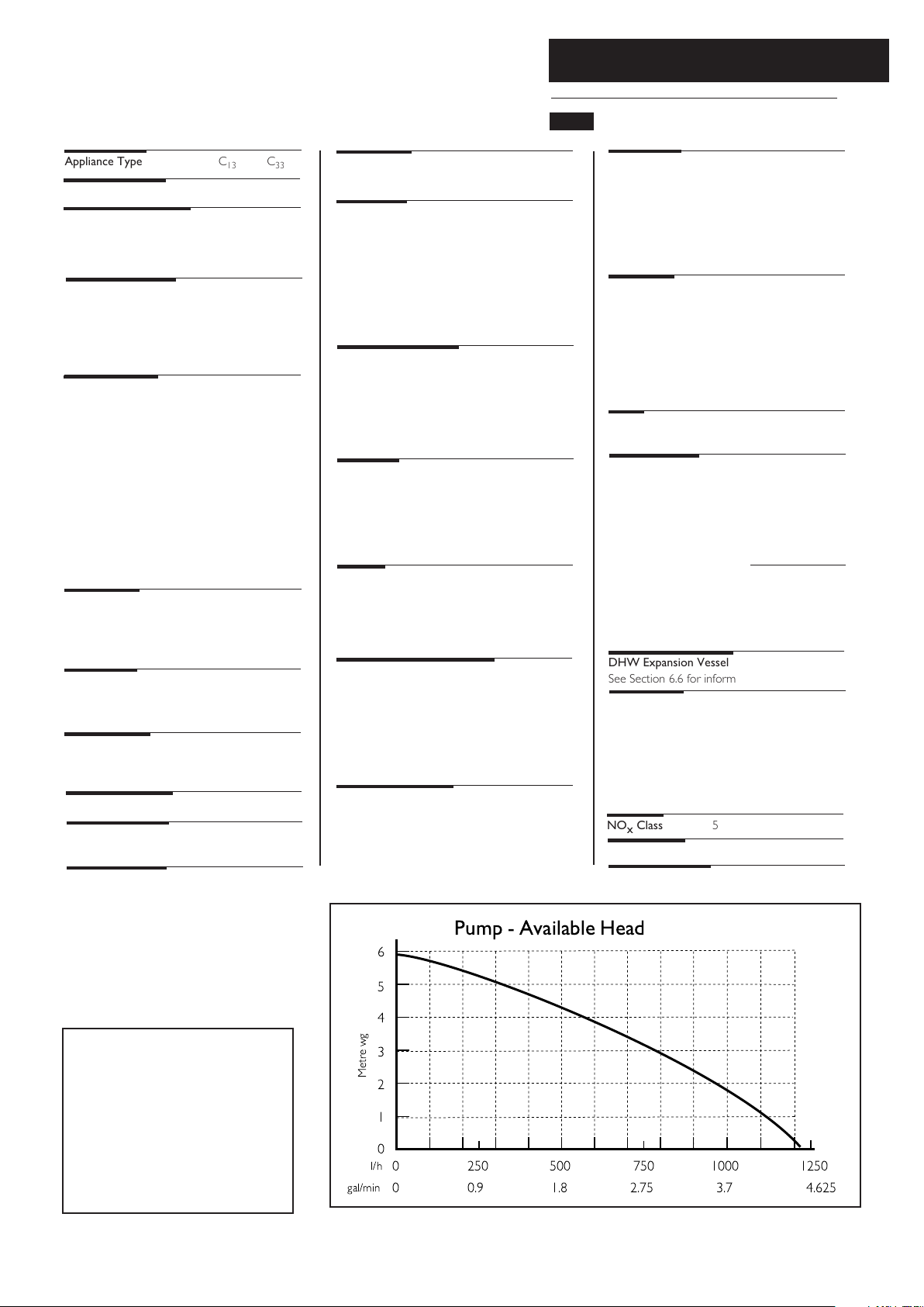
Pump
Available Head See graph below
Expansion Vessel - (For Central Heating
only. Integral with appliance)
bar lb/in
2
Min Pre-charge Pressure 0.95 13.8
Nominal Pre-charge
Pressure 1 14.5
litre gal
Max Capacity of
CH System 125 27.5
Primary Water Content
of Boiler (unpressurised) 3.5 6.2
Connections compression
Gas Supply -1/2” BSPF
Central Heating Flow - 22mm
Central Heating Return - 22mm
Cold Water Mains Inlet - 15mm
DHW Flow - 15mm
Pressure Relief Discharge - 15mm
Condensate Drain - 1” BSP
Recommended System
Temperature Drop
Condensing 20°C
Temperatures
C.H. Flow Temp (adjustable)
55° C to 82° C max (± 0.5° C)
D.H.W. Flow Temp (adjustable)
45° C to 55° C max (± 0.5° C)
dependent upon flow rate
Heat Input Gross DHW Max
kW 45.45
Btu/h 155,000
Heat Output CH
Non Condensing (70°C Mean Water temp)
Max Factory Set
kW 30.0 23.9
Btu/h 102,000 81,500
Condensing (40°C Mean Water temp)
Max Factory Set
kW 31.4 25.1
Btu/h 107,000 85,600
Electrical Supply 230V~ 50H
z
(Appliance must be connected to an
earthed supply)
Power Consumption 200W
External Fuse Rating 3A
Internal Fuse Rating 3.15A
Appliance Category CAT I
2H
Max Gas Rate (Natural Gas)
(After 10 Mins)
m3/h 4.2
ft3/h 148.3
Inlet Pressure (Natural Gas)
mbar 20
in wg 8
Appliance Type C
13
C
33
NOxClass 5
DHW Expansion Vessel
See Section 6.6 for information
The efficiency is 90.7 %
This value is used in the UK Government’s
Standard Assessment Procedure (SAP) for energy
rating of dwellings. The test data from which it has
been calculated has been certified by 0086.
SEDBUK Declaration For
Combi 133 HE Plus
Heat Input Gross CH
Max Factory Set
kW 33.7 26.95
Btu/h 115,000 92,000
CO/CO2Ratio 0.002
4.1 Combi 133 HE Plus
Electrical Protection IPX4
Page 10
4.0 Technical Data
10
© Baxi Heating UK Limited 2005
Flue Terminal Diameter 110mm
Dimensions Projection 150mm
Outercase Dimensions
Casing Height - 850mm
Overall Height Inc Flue
Elbow - 1000mm
Casing Width - 490mm
Casing Depth - 320mm
Clearances
Both Sides 5mm Min
Above Casing 200mm Min
Below Casing 200mm Min
Front 500mm Min (For Servicing)
Front 5mm Min (In Operation)
Weights kg lb
Packaged Boiler Carton 58.2 128.3
Packaged Flue Kit 3.8 8.4
Weight Empty 53.2 117.3
Installation Lift Weight 44.4 98
Central Heating Primary Circuit
Pressures
bar lb/in
2
Safety Discharge 3 43.5
Max Operating 2.5 36.3
Min Operating 0.7 10.2
Recommend Operating 1-2 14.5-29
DHW Circuit bar lb/in
2
Pressures
Max Operating 10 145
Min Operating 0.1 1.45
Min Operating Pressure
at 12 l/min 0.54 7.83
Flow Rates l/min gal/min
DHW Flow Rate
@ 30o C Rise 14 3.08
DHW Flow Rate
@ 35o C Rise 12 2.64
Min Working
DHW Flow Rate 1.9 0.43
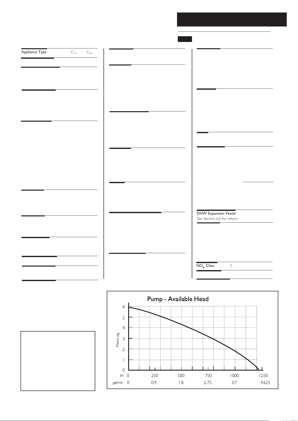
Pump
Available Head See graph below
Expansion Vessel - (For Central Heating
only. Integral with appliance)
bar lb/in
2
Min Pre-charge Pressure 0.95 13.8
Nominal Pre-charge
Pressure 1 14.5
litre gal
Max Capacity of
CH System 125 27.5
Primary Water Content
of Boiler (unpressurised) 3.5 6.2
Connections compression
Gas Supply -1/2” BSPF
Central Heating Flow - 22mm
Central Heating Return - 22mm
Cold Water Mains Inlet - 15mm
DHW Flow - 15mm
Pressure Relief Discharge - 15mm
Condensate Drain - 1” BSP
Recommended System
Temperature Drop
Condensing 20°C
Temperatures
C.H. Flow Temp (adjustable)
55° C to 82° C max (± 0.5° C)
D.H.W. Flow Temp (adjustable)
45° C to 55° C max (± 0.5° C)
dependent upon flow rate
Heat Input Gross DHW Max
kW 33.7
Btu/h 115,000
Heat Output CH
Non Condensing (70°C Mean Water temp)
Max Factory Set
kW 30.0 23.9
Btu/h 102,000 81,500
Condensing (40°C Mean Water temp)
Max Factory Set
kW 31.4 25.1
Btu/h 107,000 85,600
Electrical Supply 230V~ 50H
z
(Appliance must be connected to an
earthed supply)
Power Consumption 200W
External Fuse Rating 3A
Internal Fuse Rating 3.15A
Appliance Category CAT I
2H
Max Gas Rate (Natural Gas)
(After 10 Mins)
m3/h 3.1
ft3/h 110.0
Inlet Pressure (Natural Gas)
mbar 20
in wg 8
Appliance Type C
13
C
33
NOxClass 5
DHW Expansion Vessel
See Section 6.6 for information
The efficiency is 90.8 %
This value is used in the UK Government’s
Standard Assessment Procedure (SAP) for energy
rating of dwellings. The test data from which it has
been calculated has been certified by 0086.
SEDBUK Declaration For
Combi 100 HE Plus
Heat Input Gross CH
Max Factory Set
kW 33.7 26.95
Btu/h 115,000 92,000
CO/CO2Ratio 0.002
4.2 Combi 100 HE Plus
Electrical Protection IPX2
Page 11
4.0 Technical Data
11
© Baxi Heating UK Limited 2005
Flue Terminal Diameter 110mm
Dimensions Projection 150mm
Outercase Dimensions
Casing Height - 850mm
Overall Height Inc Flue
Elbow - 1000mm
Casing Width - 490mm
Casing Depth - 320mm
Clearances
Both Sides 5mm Min
Above Casing 200mm Min
Below Casing 200mm Min
Front 500mm Min (For Servicing)
Front 5mm Min (In Operation)
Weights kg lb
Packaged Boiler Carton 58.2 128.3
Packaged Flue Kit 3.8 8.4
Weight Empty 53.2 117.3
Installation Lift Weight 44.4 98
Central Heating Primary Circuit
Pressures
bar lb/in
2
Safety Discharge 3 43.5
Max Operating 2.5 36.3
Min Operating 0.7 10.2
Recommend Operating 1-2 14.5-29
DHW Circuit bar lb/in
2
Pressures
Max Operating 10 145
Min Operating 0.1 1.45
Min Operating Pressure
at 10 l/min 0.39 23.2
Flow Rates l/min gal/min
DHW Flow Rate
@ 30o C Rise 11.7 2.57
DHW Flow Rate
@ 35o C Rise 10 2.20
Min Working
DHW Flow Rate 1.9 0.43
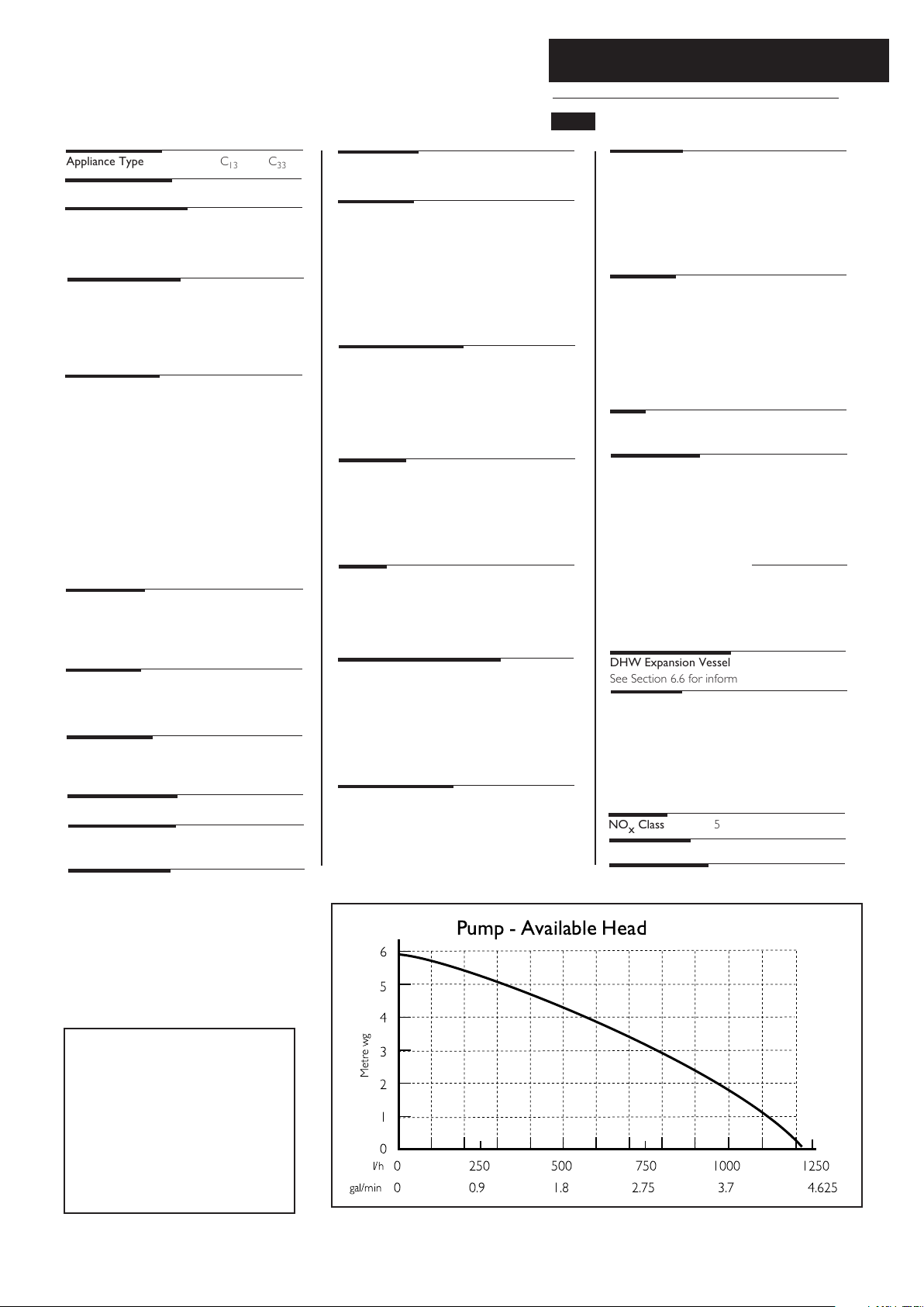
Pump
Available Head See graph below
Expansion Vessel - (For Central Heating
only. Integral with appliance)
bar lb/in
2
Min Pre-charge Pressure 0.95 13.8
Nominal Pre-charge
Pressure 1 14.5
litre gal
Max Capacity of
CH System 125 27.5
Primary Water Content
of Boiler (unpressurised) 3.5 6.2
Connections compression
Gas Supply -1/2” BSPF
Central Heating Flow - 22mm
Central Heating Return - 22mm
Cold Water Mains Inlet - 15mm
DHW Flow - 15mm
Pressure Relief Discharge - 15mm
Condensate Drain - 1” BSP
Recommended System
Temperature Drop
Condensing 20°C
Temperatures
C.H. Flow Temp (adjustable)
55° C to 82° C max (± 0.5° C)
D.H.W. Flow Temp (adjustable)
45° C to 55° C max (± 0.5° C)
dependent upon flow rate
Heat Input Gross DHW Max
kW 26.95
Btu/h 92,000
Heat Output CH
Non Condensing (70°C Mean Water temp)
Max
kW 23.9
Btu/h 81,500
Condensing (40°C Mean Water temp)
Max
kW 25.1
Btu/h 85,600
Electrical Supply 230V~ 50H
z
(Appliance must be connected to an
earthed supply)
Power Consumption 200W
External Fuse Rating 3A
Internal Fuse Rating 3.15A
Appliance Category CAT I
2H
Max Gas Rate (Natural Gas)
(After 10 Mins)
m3/h 2.5
ft3/h 87.9
Inlet Pressure (Natural Gas)
mbar 20
in wg 8
Appliance Type C
13
C
33
NOxClass 5
DHW Expansion Vessel
See Section 6.6 for information
The efficiency is 90.8%
This value is used in the UK Government’s
Standard Assessment Procedure (SAP) for energy
rating of dwellings. The test data from which it has
been calculated has been certified by 0086.
SEDBUK Declaration For
Combi 80 HE Plus
Heat Input Gross CH
Max
kW 26.95
Btu/h 92,000
CO/CO2Ratio 0.002
4.3 Combi 80 HE Plus
Electrical Protection IPX2
Page 12
5.0 Dimensions and Fixings
12
© Baxi Heating UK Limited 2005
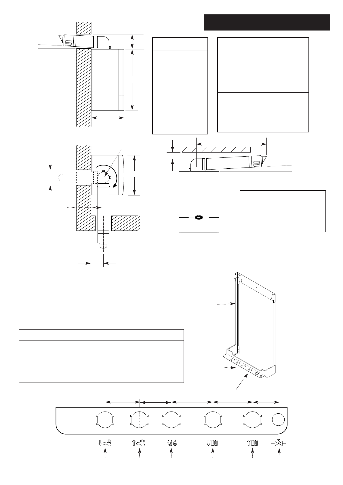
Key To Support Bracket
1 Domestic Hot Water Outlet 4 Central Heating Flow
2 Cold Water Inlet 5 Central Heating Return
3 Gas Supply 6 Pressure Relief
Support Bracket
1 2 3 4 5
63 mm
62 mm 77 mm 74.5 mm
Tap Rail
Top View
of Tap Rail
C/L
6
50 mm
360° Orientation
Tube Ø 110mm
D
C
B
A
E
F
3°
(1 in 20)
DIMENSIONS
A 850mm
B 320mm
C 490mm
D 125mm Ø Min.
E 150mm
F 136mm
SIDE FLUE (left and right)
For every 1m of horizontal flue
length, the clearance above the top
of the flue elbow should be 55mm
to incorporate the 3°
(1 in 20) fall in the flue from the
terminal to the elbow.
The 3° (1 in 20) fall provided by
the elbow is to allow condensate
to run back to the boiler, for
disposal through the condensate
discharge pipe.
Flue length (Y)
up to 1m
1m - 2m
2m - 3m
Clearance (X)
55mm
110mm
165mm
Y
3°
(1 in 20)
X
Page 13

6.0 System Details
13
© Baxi Heating UK Limited 2005
6.1 Central Heating Circuit
1. The appliance is suitable for fully pumped SEALED SYSTEMS
ONLY.
This boiler is fitted with a flow switch interlock that prevents
it from firing when the heating demand is satisfied.
The boiler is designed so that it will heat the house to the
desired room temperature as quickly as possible by running
at the maximum radiator temperature of 82°C. Once this
room temperature is achieved the boiler will then reduce the
radiator temperature to as low a level as possible, while still
achieving the desired room temperature, thereby giving the
most efficient use of gas and the most comfortable room
temperature possible.
The boiler will be able to achieve this performance if a room
thermostat is fitted or with a fully TRV’d system without a
bypass.
This boiler does not require a bypass. To comply with Part
L1 of the Building Regulations the heating system into which
the boiler is installed should include the following:
a) zone controls
b) timing controls
c) boiler control interlocks
Such a system needs to be fully pumped and must provide
independent temperature and time control to both the
heating and hot water circuits and have a boiler interlock.
The boiler should be controlled so that it operates on
demand only. Where it is proposed to effect control by
thermostatic radiator valves, a room thermostat (or other
device such as a flow switch - a flow switch is integral to this
boiler) should also be provided to switch off the boiler when
there is no demand for heating or hot water.
The interlock for CH circuit can be provided in either of the
following ways:
a) A Room Thermostat with at least the radiator
nearest the room stat not TRV’d.
b) A fully TRV’d system without a bypass.
A fully TRV’d system with a bypass that has not been valved
off does not comply with Part L1 of the Building Regulations.
If the system is fully TRV’d with a bypass then this feature will
not be available, in this case the radiator temperature can be
reduced to provide more efficient operation. (see User
instructions).
• The condensate drain and pipes must be free from leaks.
Information
In GB it is necessary to comply with the Water Supply (Water Fittings)
Regulations 1999 (or for Scotland, The Water Byelaws 2000, Scotland). The Baxi
Combi 133, 100, 80 HE Plus Combination Boilers are an Approved Product under
the Water Regulations.
To comply with the Water Regulations your attention is drawn to The Water
Regulations Advisory Service (WRAS) which gives full details of the requirements.
In IE the requirements given in the current edition of I.S. 813 “Domestic Gas
Installations” and the current Building Regulations must be followed.
Treatment of Water Circulating Systems
• All recirculatory water systems will be subject to corrosion unless an
appropriate water treatment is applied. This means that the efficiency of the
system will deteriorate as corrosion sludge accumulates within the system,
risking damage to pump and valves, boiler noise and circulation problems.
• When fitting new systems flux will be evident within the system, which can
lead to damage of system components.
• All systems must be thoroughly drained and flushed out. Using for example
Betz-Dearborn Sentinel X300 or X400 or Fernox Superfloc Universal
Cleanser. They should be used following the flushing agent manufacturer’s
instructions.
• System additives - corrosion inhibitors and flushing agents/descalers should
comply to BS7593 requirements, e.g. Betz-Dearborn Sentinel X100 and
Fernox-Copal which should be used following the inhibitor manufacturer’s
instructions.
Failure to flush and add inhibitor to the system will invalidate the
appliance warranty.
• It is important to check the inhibitor concentration after installation, system
modification and at every service in accordance with the manufacturer’s
instructions. (Test kits are available from inhibitor stockists.)
• For information or advice regarding any of the above contact Technical
Enquiries.
Page 14
6.0 System Details
14
© Baxi Heating UK Limited 2005
6.2 System Control
1. The boiler is designed for use in a heating system that
incorporates external controls, i.e. a minimum of a timer
device.
2. Suitable timer kits are available as optional extras.
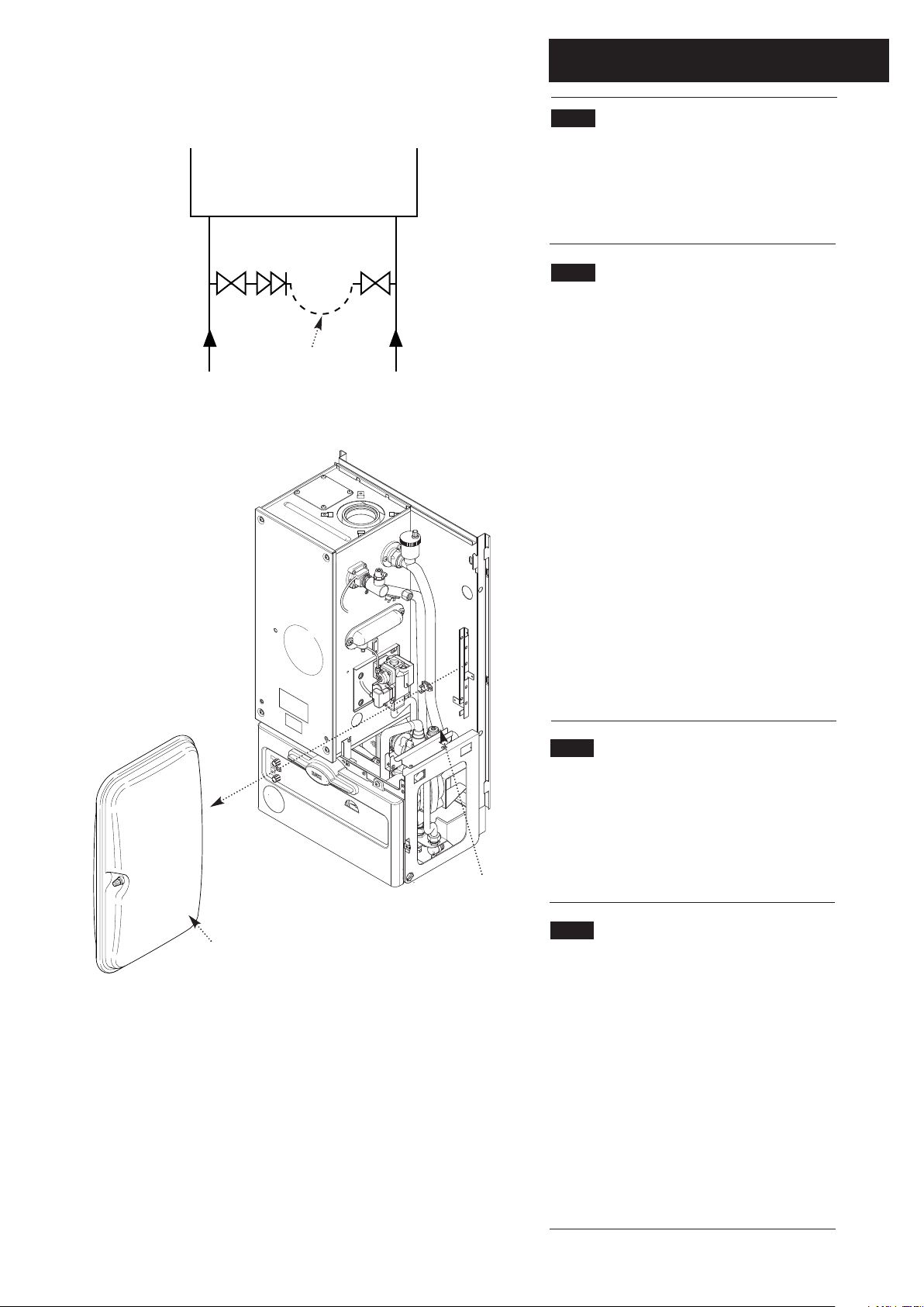
6.3 System Filling and Pressurising (Fig. 3)
1. A filling point connection on the central heating return
pipework must be provided to facilitate initial filling and
pressurising and also any subsequent water loss
replacement/refilling.
2. The filling method adopted must be in accordance with
all relevant water supply regulations and use approved
equipment.
3. Your attention is drawn to,
for GB: Guidance G24.2 and recommendation R24.2 of
the Water Regulations Guide.
for IE: the current edition of I.S. 813. "Domestic Gas
Installations".
4. The sealed primary circuits may be filled or replenished
by means of a temporary connection between the circuit
and a supply pipe, provided a 'Listed' double check valve
or some other no less effective backflow prevention
device is permanently connected at the inlet to the circuit
and the temporary connection is removed after use.
5. To aid removal of air from the system whilst filling,
move the diverter valve to the CH position by using the
installer parameters (see Section 10.4).
6.4 Expansion Vessel - CH only (Fig. 4)
1. The appliance expansion vessel is pre-charged to 1 bar
(14.5 lb/in
2
). Therefore, the minimum cold fill pressure is 1
bar. The vessel is suitable for correct operation for system
capacities up to 125 litres (27.5gal). For greater system
capacities an additional expansion vessel must be fitted.
For GB refer to BS 7074 Pt 1. For IE, the current edition
of I.S. 813 “Domestic Gas Installations”.
6.5 Pressure Relief Valve (Fig. 4 )
1. The pressure relief valve is set at 3 bar, therefore all
pipework, fittings, etc. should be suitable for pressures in
excess of 3 bar.
2. The pressure relief discharge pipe should not be less
than 15mm dia, run continuously downward, and
discharge outside the building, preferably over a drain. It
should be routed in such a manner that no hazard occurs
to occupants or causes damage to wiring or electrical
components. The end of the pipe should terminate facing
down and towards the wall.
3. The discharge must not be above a window, entrance
or other public access. Consideration must be given to
the possibility that boiling water/steam could discharge
from the pipe.
Fig. 3
Stop
Valve
Double
Check
Valve
DHW
Mains
Inlet
CH
Return
Temporary
Hose
Pressure Relief
Valve
Expansion Vessel
removed for clarity
Fig. 4
Expansion Vessel
Stop
Valve
Page 15
6.0 System Details
15
© Baxi Heating UK Limited 2005
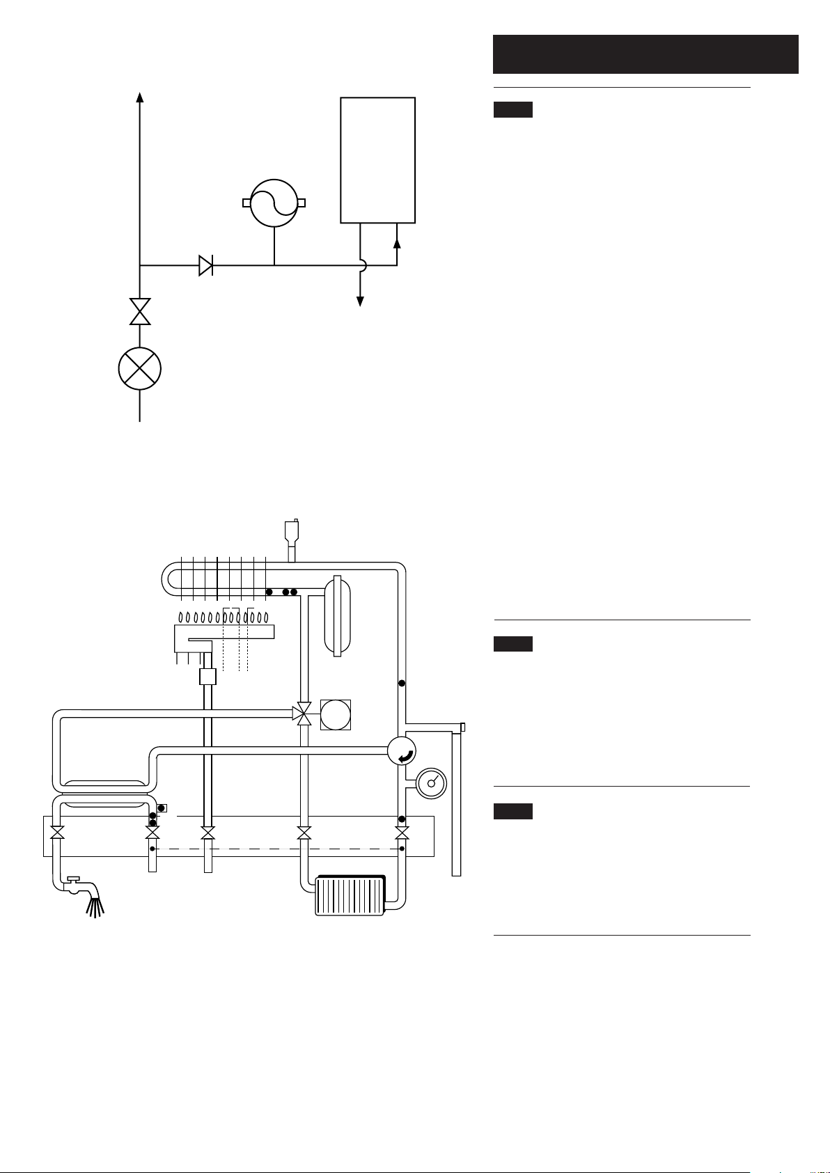
6.6 Domestic Hot Water Circuit
1. All DHW circuits, connections, fittings, etc. should be
fully in accordance with relevant standards and water
supply regulations.
2.When installed in accordance with 1 above this
appliance does not require a check valve to meet water
supply regulations. However when the system includes
any device which prevents water expanding back
towards the supply, then an expansion vessel must be
fitted (e.g. Zilmet 160ml, R
1
/215 bar).
3. If the hot water expansion is not provided for, then
high pressures can develop which may result in damage
to fittings and devices on the system.
4. The boiler’s maximum working mains pressure is 10
bar (150 lb/in2), therefore all pipework, connections,
fittings, etc. should be suitable for pressures in excess of
10 bar. A pressure reducing valve must be fitted for
pressures in excess of 10 bar. The manufacturer of any
outlet fittings, such as a shower valve, may require a
lower maximum pressure. The pressure reduction must
take account of all fittings connected to the DHW
system.
5. Optimum hot water delivery of 16 l/min (133 model),
12 l/min (100 model), 10 l/min (80 model) may be
obtained by fitting the flow regulator supplied.
6.7 Showers
1. If a shower control is supplied from the appliance it
should be of the thermostatic or pressure balanced type.
Thermostatic type shower valves provide the best
comfort and guard against water at too high a
temperature. Existing controls may not be suitable refer to the shower valve manufacturer.
6.8 Hard Water Areas
1. If the area of the installation is recognised as a HARD
WATER AREA then a suitable device should be fitted to
treat the mains water supply to the boiler. Contact your
Water Distribution Company for advice on suitable
devices.
Key
1 Expansion Vessel
2 Flow Thermostat
3 Flow Thermistor
4 Flow Switch
5 Primary Heat Exchanger
6 Gas Valve
7 DHW Plate Heat Exchanger
8 DHW Flow
9 DHW Mains Inlet
10 Flow Regulator
11 DHW Flow Switch
Boiler
Other Tap
Outlets
Expansion
Vessel
To Hot
Taps
Check
Valve
Pressure Reducer
Valve
Stop Tap
V
M
12 Gas Inlet
13 Filling Loop
14 CH Flow Valve
15 Filter
16 CH Return Valve
17 Pressure Gauge
18 Pump
19 Pressure Relief Valve
20 Return Thermistor
21 3 Way Valve
1
5
43
2
20
21
7
18
17
14
129
11
16
19
13
10
15
6
8
15
Page 16
7.0 Site Requirements
16
© Baxi Heating UK Limited 2005
Zone 2
Zone 1
Zone 0
Zone 2
Zone 3
Zone 3
Zone 2
Window
Recess
Window
Recess
0.6 m
2.4 m
Ceiling
Outside
Zones
Outside Zones
Zone 3
Zone 3
Zone 2
Zone 2
Zone 1
Zone 0
2.25 m
Zone 2
Window
Recess
3.0 m
2.4 m
0.6 m
Fig. A
Fig. B
In GB Only
In GB Only
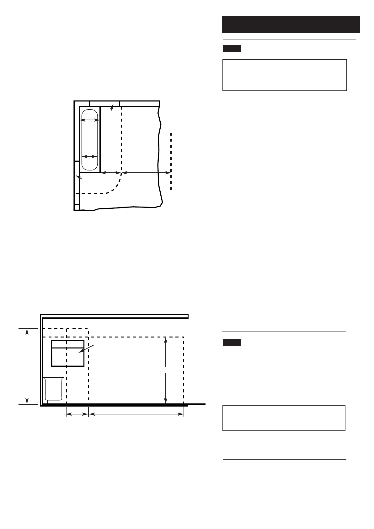
7.1 Location
NOTE: Due to the high efficiency of the boiler a
plume of water vapour will be discharged from the
flue. This should be taken into account when siting
the flue terminal.
1. The boiler may be fitted to any suitable non-flammable
wall with the flue passing through an outside wall or roof
and discharging to atmosphere in a position permitting
satisfactory removal of combustion products and providing
an adequate air supply. The boiler should be fitted within
the building unless otherwise protected by a suitable
enclosure i.e. garage or outhouse. (The boiler may be fitted
inside a cupboard - see Section 7.2).
2. If the boiler is sited in an unheated enclosure then it is
recommended to incorporate an appropriate device for
frost protection in the system controls.
3. If the boiler is fitted in a room containing a bath or
shower, the 100 HE Plus and 80 HE Plus can only be fitted
in zone 3, the 133 HE Plus has a higher protection level
and may be fitted in zone 2 (Figs. A & B shows zone
dimensions for a bathtub. For other examples refer to
Section 601 of the Current I.E.E. Wiring Regulations)
reference must be made to the relevant requirements.
In GB this is the current I.E.E. Wiring Regulations and
Building Regulations.
In IE reference should be made to the current edition of I.S.
813 “Domestic Gas Installations” and the current ETCI
rules.
4. If the boiler is to be fitted into a building of timber frame
construction then reference must be made to the current
edition of Institute of Gas Engineers Publication IGE/UP/7
(Gas Installations in Timber Framed Housing.
7.2 Ventilation of Compartments
1. Where the appliance is installed in a cupboard or
compartment, no air vents are required. The appliance
will run sufficiently cool without extra ventilation.
Minimum Cupboard Size (inside dimensions)
Height - 1250mm Width - 590mm Depth - 400mm
NOTE: The ventilation label on the front of the outer
case MUST NOT BE REMOVED when the appliance
is installed in a compartment or cupboard.
2. BS 5440: Part 2 Clause 4.2 refers to room sealed
appliances installed in compartments.
Page 17

7.0 Site Requirements
17
© Baxi Heating UK Limited 2005
7.3 Clearances (Fig. 6 & 7)
1. A flat vertical area is required for the installation of the
boiler.
2. These dimensions include the necessary clearances
around the boiler for case removal, spanner access and air
movement. Additional clearances may be required for the
passage of pipes around local obstructions such as joists
running parallel to the front face of the boiler.
7.4 Gas Supply
1. The gas installation should be in accordance with the
relevant standards. In GB this is BS 6891. In IE this is the
current edition of I.S. 813 “Domestic Gas Installations”.
2. The connection to the appliance is a
1
/2” BSPF.
3. Ensure that the pipework from the meter to the
appliance is of adequate size. Do not use pipes of a smaller
diameter than 22mm up to the boiler connection.
7.5 Electrical Supply
1. External wiring must be correctly earthed, polarised and
in accordance with relevant regulations/rules. In GB this is
the current I.E.E. Wiring Regulations. In IE reference should
be made to the current edition of ETCI rules.
NOTE: The method of connection to the electricity
supply must facilitate complete electrical isolation of the
appliance. Connection must be via a fused double-pole
isolator with a contact separation of at least 3mm in all
poles and servicing the boiler and system controls only.
WARNING: The PCB Control and Fan Assembly
is 325 Vdc. Isolate at supply before access.
200mm
850mm
490mm
200mm
5mm Min
5mm Min
5mm
500mm
For Servicing
Purposes
Fig. 6
Fig. 7
In Operation
3°
(1 in 20)
320mm
Page 18
7.0 Site Requirements
18
© Baxi Heating UK Limited 2005
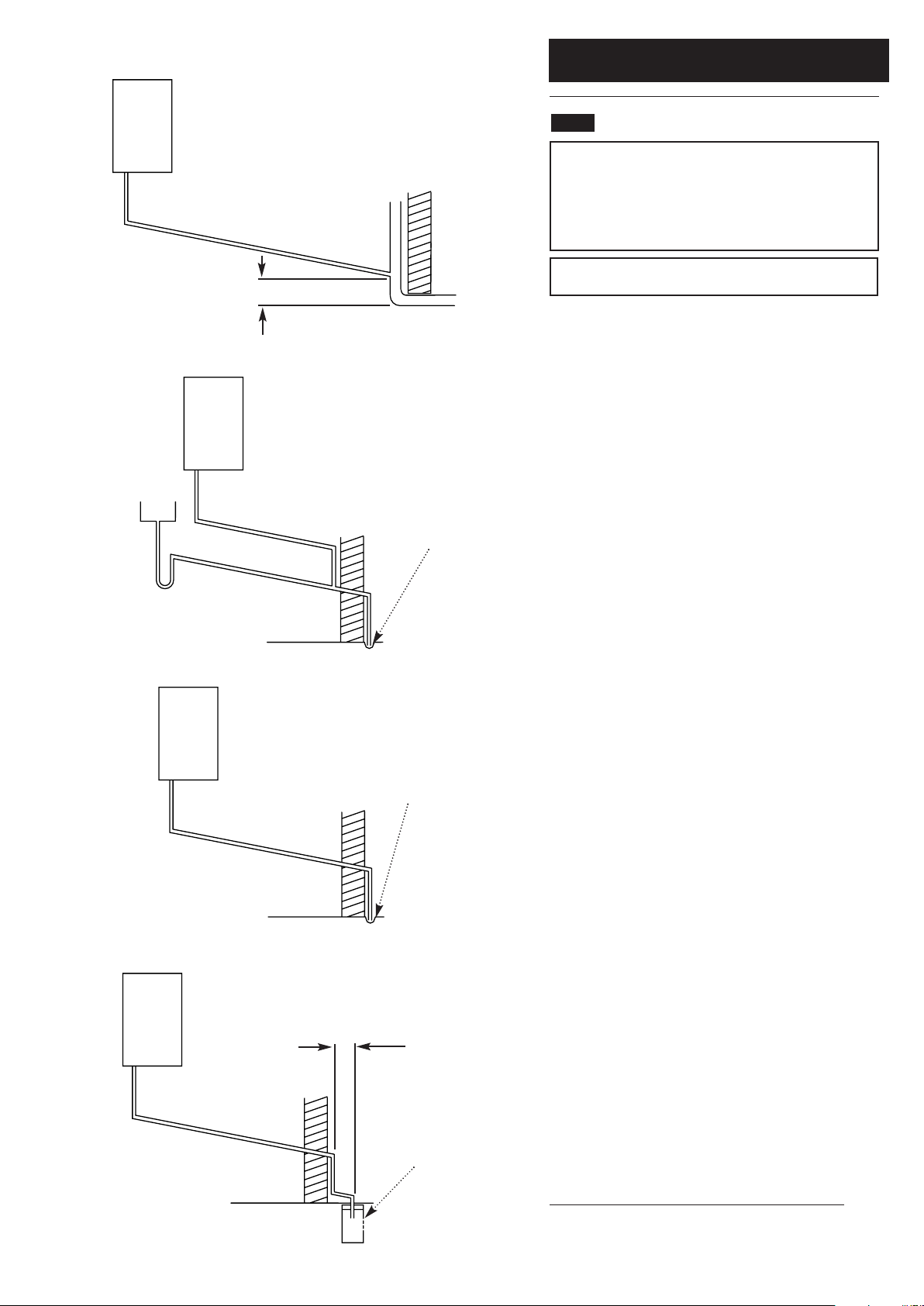
7.6 Condensate Drain
FAILURE TO INSTALL THE CONDENSATE
DISCHARGE PIPEWORK CORRECTLY WILL AFFECT
THE RELIABLE OPERATION OF THE BOILER
The condensate discharge pipe MUST NOT RISE at any
point along its length. There MUST be a fall of AT LEAST
2.5° (50mm per metre) along the entire run.
NOTE: It is unnecessary to fit an air break in the
discharge pipe.
1. The condensate outlet terminates in a 1” BSP nut and seal
for the connection of 21.5mm (
3
/4in) plastic overflow pipe
which should generally discharge internally into the household
drainage system. If this is not possible, discharge into an
outside drain is acceptable.
2. Ensure the discharge of condensate complies with any
national or local regulations in force.
BS 6798:2000 & Part H1 of the Building Regulations give
further guidance.
3. The discharge pipe should be run in a proprietary drain pipe
material e.g. PVC, PVC-U, ABS, PVC-C or PP.
4. Metal pipework is NOT suitable for use in condensate
discharge systems.
5. The pipe should be a minimum of 21.5mm diameter and
must be supported using suitably spaced clips to prevent
sagging.
6. It is advisable to keep the condensate pipe internal.
7. External runs greater than 3 metres or runs in cold areas
should use 32mm waste pipe.
8. If the boiler is fitted in an unheated location the entire
condensate discharge pipe should be treated as an external
run.
9. In all cases discharge pipe must be installed to aid disposal
of the condensate. To reduce the risk of condensate being
trapped, as few bends and fittings as possible should be used.
10. When discharging condensate into a soil stack or waste
pipe the effects of existing plumbing must be considered. If soil
pipes or waste pipes are subjected to internal pressure
fluctuations when WC's are flushed or sinks emptied then
back-pressure may force water out of the boiler trap and
cause appliance lockout.
Examples are shown of the following methods of termination:i) to an internal soil & vent pipe
ii) via an internal discharge branch (e.g. sink waste)
iii) to a drain or gully
iv) to a purpose made soakaway
Boiler
2.5° Minimum fall
Termination to an internal soil and
vent pipe
450mm min
Boiler
2.5° Minimum fall
External termination via internal discharge
branch
e.g sink waste - downstream
Sink
Pipe must terminate
above water level but
below surrounding
surface
Boiler
Pipe must terminate above
water level but below
surrounding surface
2.5° Minimum fall
Termination to a drain or gully
Boiler
500mm min
2.5° Minimum fall
Termination to a purpose made soak-
away
Holes in the soak-away must
face away from the building
50mm per metre of pipe run
50mm per metre of pipe run
50mm per metre of pipe run
50mm per metre of pipe run
Page 19
7.0 Site Requirements
19
© Baxi Heating UK Limited 2005
!
"
#
$
%
7.7 Flue
NOTE: Due to the high efficiency of the boiler a
plume of water vapour will be discharged from the
flue. This should be taken into account when siting
the flue terminal.
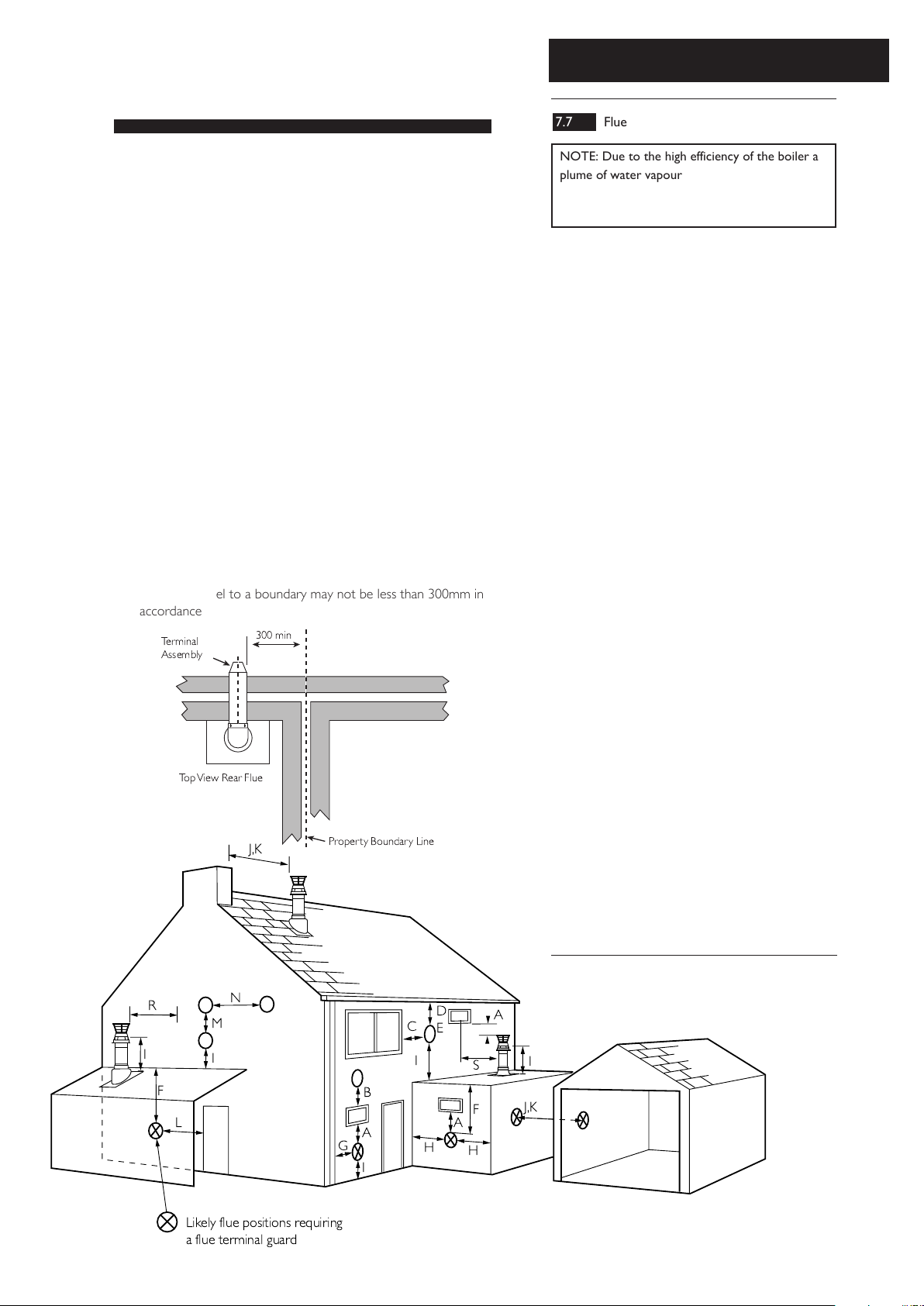
1. The following guidelines indicate the general
requirements for siting balanced flue terminals.
For GB recommendations are given in BS 5440 Pt 1.
For IE recommendations are given in the current
edition of I.S. 813 “Domestic Gas Installations”.
2. If the terminal discharges onto a pathway or
passageway, check that combustion products will not
cause a nuisance and that the terminal will not obstruct
the passageway.
3. Take into consideration the effect the plume of
vapour may have on neighbours when siting the flue.
4. Adjacent surfaces close to the flue terminal may need
protection from the effects of condensation.
Alternatively a flue deflector kit (part no. 248167) is
available.
5. For installation of the flue into an internal corner at
the 25mm dimension the flue deflector kit (part no.
248167) must be fitted.
6. * Reduction to the boundary is possible down to
25mm but the flue deflector kit (part no. 248167) must
be fitted.
7. If required a suitable terminal guard is available from
Baxi for use with the flue deflector.
8. For fitting under low soffits and eaves it is acceptable
for the flue to project upto 500mm from the face of
the wall to the inside of the air intake. This can be
painted if required using a suitable external paint.
9. If a terminal is less than 2 metres (78
3
/4in) above a
balcony, above ground or above a flat roof to which
people have access, then a suitable terminal guard must
be provided.
Fig. 10
Fig. 9
300 min
Terminal
Assembly
TopViewRear Flue
Property Boundary Line
NOTE: The distance from a fanned draught appliance terminal
installed parallel to a boundary may not be less than 300mm in
accordance with the diagram below
Table. 2
Terminal Position with Minimum Distance (Fig. 10) (mm)
AaDirectly below an opening, air brick, opening
windows, etc. 300
BaAbove an opening, air brick, opening window etc. 300
CaHorizontally to an opening, air brick, opening window etc. 300
D Below gutters, soil pipes or drain pipes. 25
E Below eaves. 25
F Below balconies or car port roof. 25
G From a vertical drain pipe or soil pipe. 25
H From an internal
(i)
or external
(ii)
corner.
(i)
25
(ii)
115
I Above ground, roof or balcony level. 300
J From a surface or boundary line facing a terminal. 600
K From a terminal facing a terminal (Horizontal flue). 1200
From a terminal facing a terminal (Vertical flue). 600
L From an opening in carport (e.g. door, window)
into the dwelling. 1200
M Vertically from a terminal on the same wall. 1500
N Horizontally from a terminal on the same wall. 300
R From adjacent wall to flue (vertical only). 300
S From an adjacent opening window (vertical only). 1000
a
In addition, the terminal should be no nearer than 150 mm to an
opening in the building fabric formed for the purpose of accommodating
a built-in element such as a window frame. See BS 5440 Pt. 1.
*
Page 20

7.0 Site Requirements
20
© Baxi Heating UK Limited 2005
7.8 Flue Dimensions
See Section 2.2. The standard horizontal flue kit allows
for flue lengths between 270mm and 800mm from
elbow to terminal (Fig. 11).
The maximum permissible equivalent flue length is: 4
metres horizontal (Fig. 12).
NOTE: Each additional 45° of flue bend will
account for an equivalent flue length of 0.5m.
eg. 45° = 0.5m, 90° = 2 x 45° = 1m etc.
7.9 Terminal Guard (Fig. 13)
1. When codes of practice dictate the use of terminal
guards, they can be obtained from most Plumbers’ and
Builders’ Merchants.
2. There must be a clearance of at least 50mm
between any part of the terminal and the guard.
3. When ordering a terminal guard, quote the
appliance name and model number.
4. The flue terminal guard should be positioned
centrally over the terminal and fixed as illustrated.
Fig. 11
Fig. 12
Pictorial examples of flue runs where EQUIVALENT flue length equals 4m
Fig. 13
270mm
800mm
0.5m
1m
1m
0.5m
Page 21
7.0 Site Requirement
21
© Baxi Heating UK Limited 2005
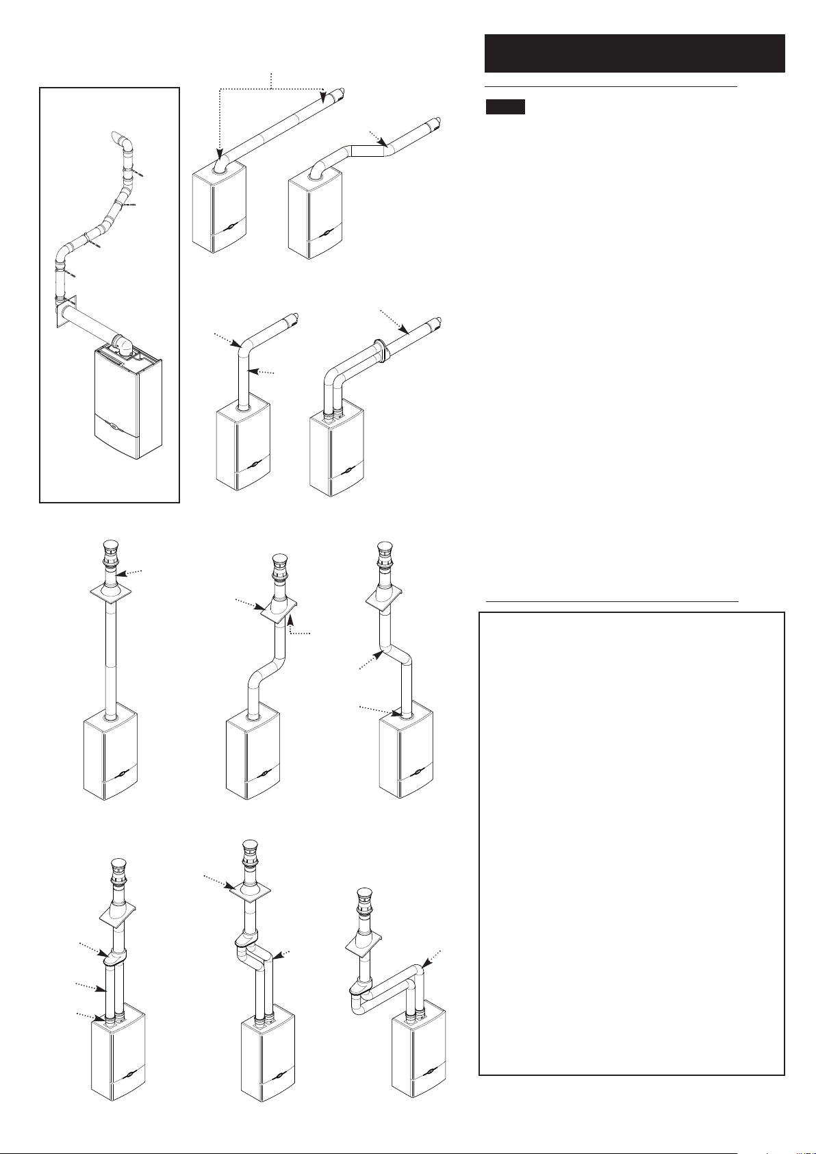
Key Accessory Size Baxi Code
Number
Concentric Flue System 110mm diameter
A Horizontal flue kit 850mm 236921
B Straight extension kit 1000mm 241695
500mm 241694
250mm 241692
C Bend kit 93° 241687
D Bend kit (pair) 45° 241689
E Horizontal flue terminal 243013BAX
Clamp 110mm 243014BAX
Twin Flue System 80mm diameter
F Straight extension kit 1000mm 238690
500mm 238692
250mm 238694
G Bend kit 90° 246139
H Bend kit (pair) 45° 246138
Universal Vertical Flue Kits
J Twin flue adaptor kit 242757
K Vertical flue terminal 242802
L Universal roof tile 25°/50° 243015
M Roof cover plate kit 243131
N Flat roof flashing 243016BAX
R Boiler connection vertical concentric 242886
Clamp 80mm 238684
7.10 Flue options
Concentric
The maximum equivalent lengths are 4m (horizontal) or
5m (vertical). There lengths exclude the standard elbow
and flue/terminal assembly (horizontal) and terminal
assembly (vertical).
Twin Flue
The total maximum equivalent flue length is 40m.
NOTE: Each 1m of flue duct should be calculated as 2m.
Any additional “in line” bends in the flue system must be
taken into consideration. Their equivalent lengths are:
Concentric Pipes: 45º bend 0.5 m
93º bend 1.0 m
Twin Flue Pipe: 45º bend (air duct) 1.3 m
45º bend (flue duct) 2.6 m
90º bend (air duct) 4.8 m
90º bend (flue duct) 9.6 m
Detailed examples of equivalent flue length calculation are
given in the Installation Guidance Notes for each flue
system type.
(Documents 243501 and 243502 for concentric and twin
pipe respectively).
A - Standard Flue
D
C
B
E
K
L
M
D
J
F
J
N
H
G
R
Plume Displacement
70/110 dia Kit
Page 22
8.0 Installation
22
© Baxi Heating UK Limited 2005
8.1 Initial Preparation
Check Site Requirements (section 7.0) before commencing.
The gas supply, gas type and pressure must be checked for
suitability before connection (see Section 7.4).
NOTE: If the boiler is to be pre-plumbed, follow both
these instructions and those on the boiler pack.
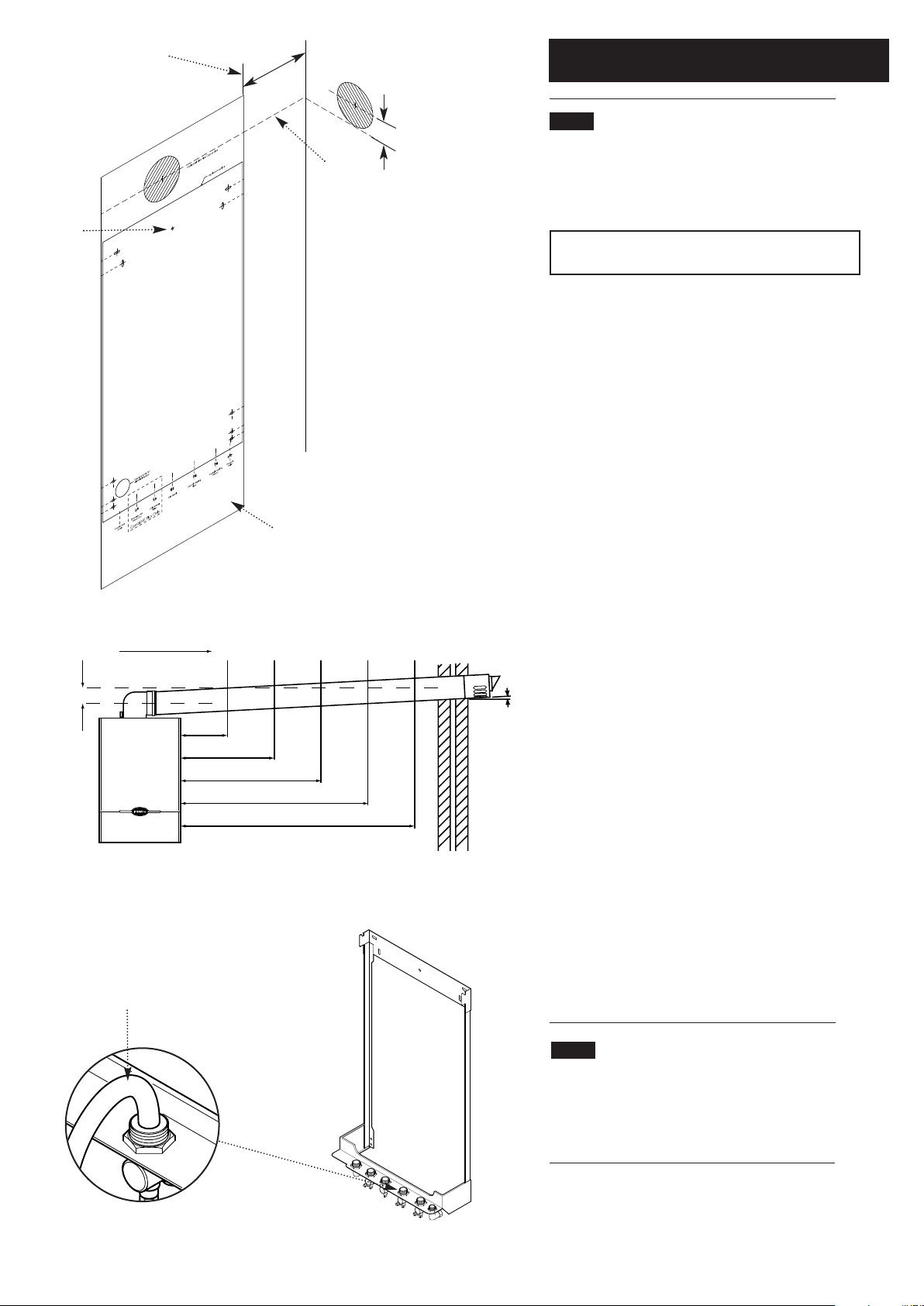
1. Remove the fixing template (Fig. 14) from the fixing
carton.
2. Position the template on the wall ensuring it is level both
horizontally and vertically.
3. Mark the position of the top centre hole for the wallplate.
4. Mark the condensate discharge pipe area.
5. Mark the centre of the flue hole (rear exit).
For side exit: project the horizontal side flue centre line into
the corner of the room and along the wall to where the flue
hole will be drilled (Fig. 14).
The diagram (Fig.14a) shows the dimensions required to
ensure any horizontal flue is installed with the correct fall to
the boiler. Mark the offset (V) dimension and if required,
mark the position of the gas and water pipes. Remove the
template.
6. Cut the hole for the flue (preferably with a 125mm/5”
diameter core boring tool), ensuring that the hole is drill at
approx 3° up from the horizontal. Both wall faces
immediately around the cut hole should be flat.
7. Drill and plug the wall as previously marked. Secure the
wallplate to the wall by the top centre hole.
8. Ensuring the wallplate is level both horizontally and
vertically, drill and plug the remaining 4 securing positions at
the top and bottom through the wallplate. Utilising the slots
available ensure the wallplate is square and secure to the
wall.
9. Connect the gas,water and the pressure relief discharge
pipes to the valves on the support bracket using the
compression fittings supplied.
10. Loosely route the condensate discharge pipe to the area
previously marked.
8.2 Flushing
1. Insert a tube into the valve outlet furthest from the filling
loop (Fig. 15).
2. Flush thoroughly (see System Details, Section 6.0).
Plastic Flushing Tube
Fig. 15
Fig. 14
The symbols for each connection are on the support bracket.
0.5
1.0
2.0
3.0
4.0
Distance in metres from boiler to the wall.
For pipe lengths greater than 4m increase the off-set by 52mm
for every additional metre to maintain approx 3° inclination.
V
Flue Duct Hole
Offset V (mm)
27 55 110 165 220
(metres)
(mm)
3°
Backfall to the Boiler, ie. 2m flue offset (V) position 110mm
Horizontal
Side Flue
Centre Line
EXAMPLE: Boiler is 2 metres away
from corner of wall, flue duct hole is
110mm up from horizontal side flue
centre line. This will maintain the
approx 3° backfall to the boiler.
Wall Plate Template
Edge of Boiler
Example
2m
Example
V = 110mm
Centre
Hole
Fig. 14a
Page 23
8.0 Installation
23
© Baxi Heating UK Limited 2005
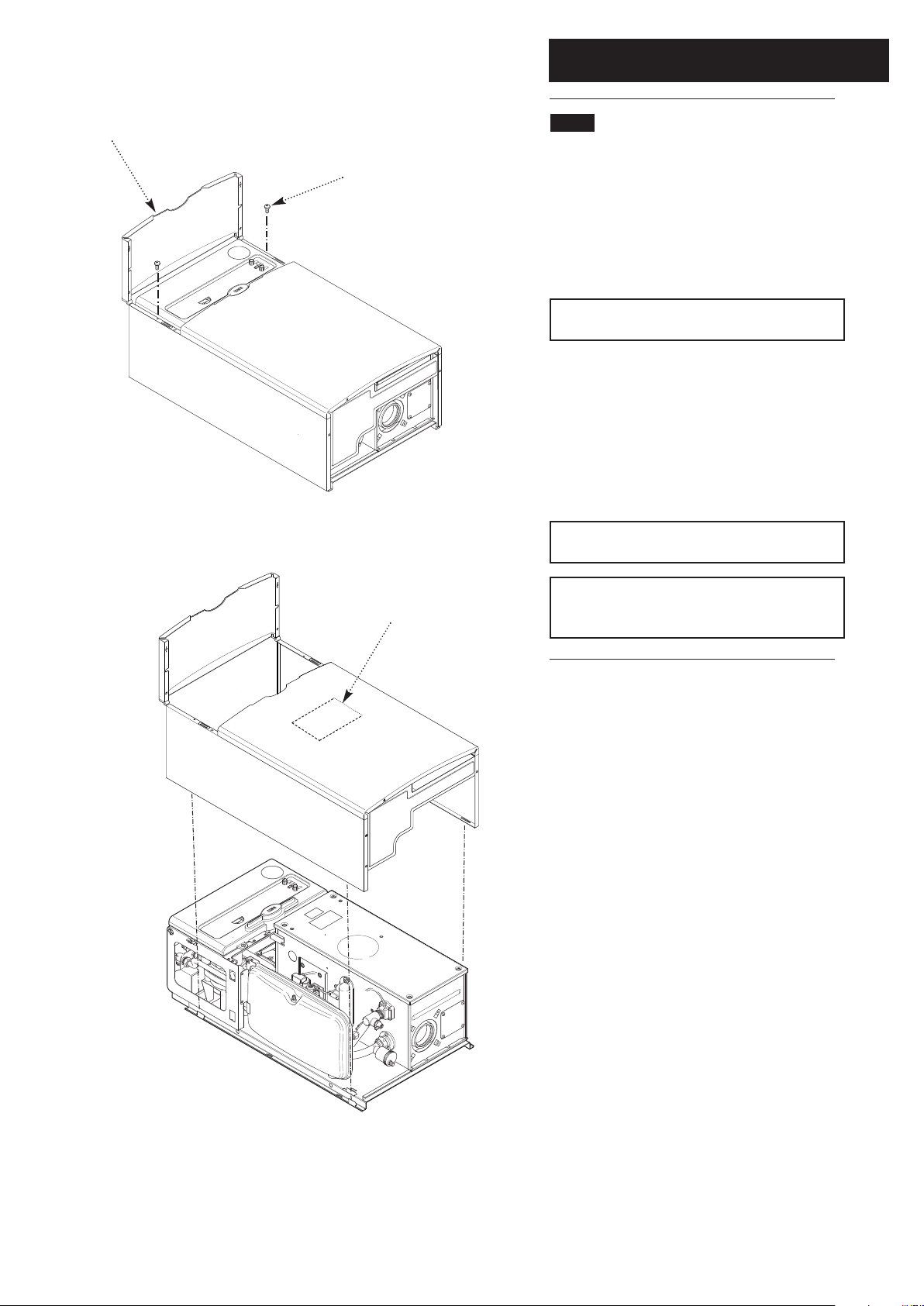
Fig. 16
Fig. 17
Outer Case Fixing
Screw
Lower Door
Panel
Service Guidance Note Label
on inside of panel
8.3 Preparing The Boiler
1. Remove the outer carton.
2. Hinge up the lower door panel (Fig. 16).
3. Remove the outer case fixing screws (Fig. 16). Slide
the outercase upwards to disengage the hooks on the
backplate and remove (Fig. 17).
NOTE: Service Guidance Note Label is fitted to
the inside of the outercase (Fig. 17).
4. Remove the sealing plugs from the copper bends.
5. Remove cardboard transit packaging at the left hand
rear of the boiler before lifting the boiler onto the
support bracket.
6. Stand the boiler on its base by using the rear lower
edge as a pivot.
NOTE: A small amount of water may drain from
the boiler in the upright position.
Baxi declare that no substances harmful to health
are contained in the appliance or used during
construction of the appliance.
Page 24
8.0 Installation
24
© Baxi Heating UK Limited 2005
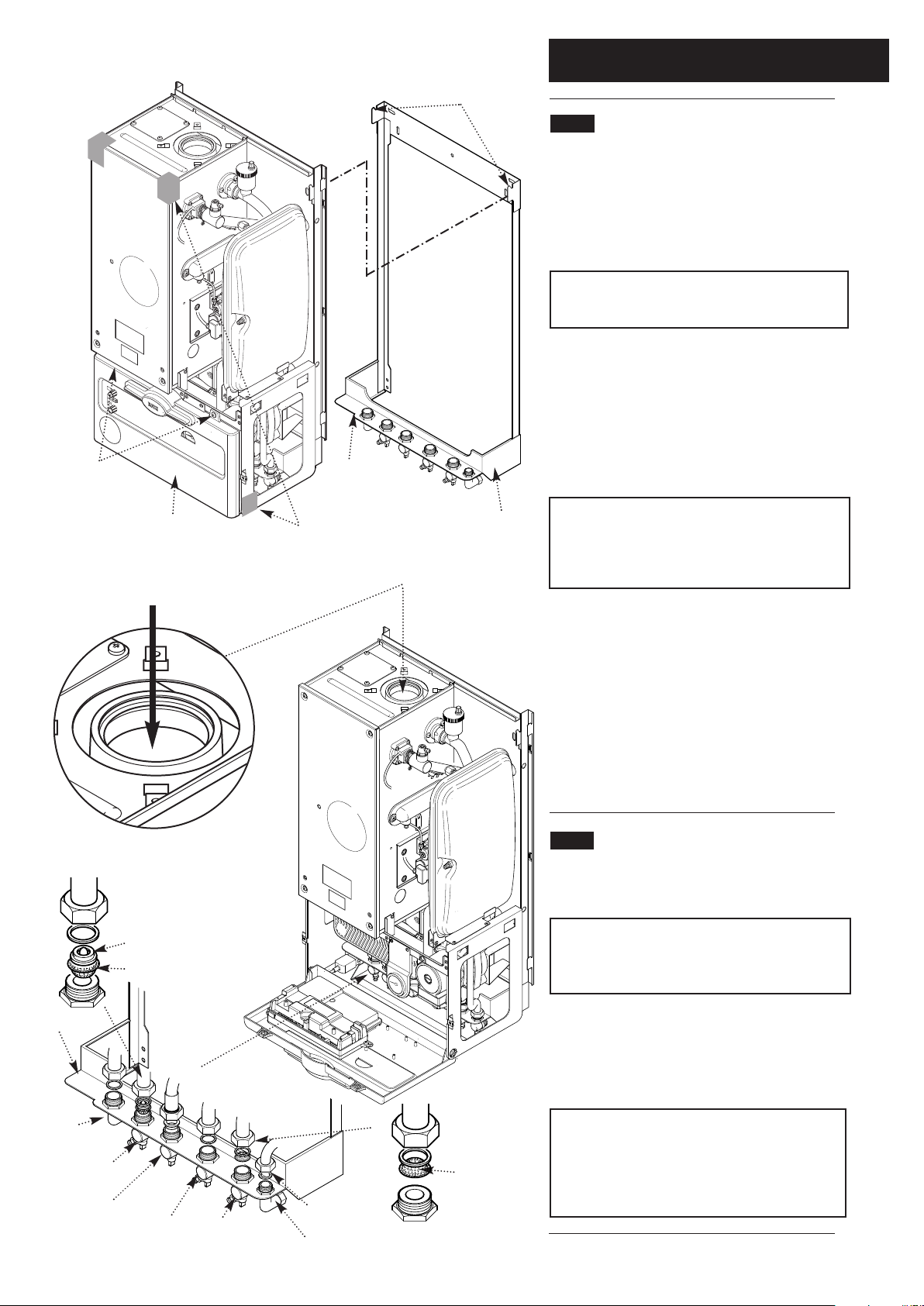
8.4 Fitting The Boiler (Fig. 18)
1. Remove the tape from the tap rail on the support
bracket.
2. Lift the boiler over the support bracket using the lifting
points shown in Fig. 18 and engage onto the top hooks
(see Lifting paragraph page 4).
NOTE: When installing in Loft/Small Compartment
access for lifting the boiler from the front can be
gained for two people using the lifting points (Fig. 18).
3. To gain access to the connections between boiler and
valves, release the facia securing screws (
1
/4turn) and
hinge down the facia box.
4. Make the connections in the following sequence:
a) Gas connection first to centralise the boiler. The gas
sealing washer is an integral part of the gas tap.
The Combi HE is designed to operate under nominal
water supply conditions. If the hot water delivery is
greater than 18 l/min (133 model), 14 l/min (100
model), 12 l/min (80 model) the flow regulator must be
fitted to the Domestic Hot Water inlet.
b) Domestic hot water cold feed, if necessary fit the
water flow regulator ensuring that it is fitted the correct
way round (Fig. 20). NOTE: Ensure water inlet filter is
fitted.
c) The remaining connections ensuring the fibre sealing
washers are inserted between the valve outlet face and
the flange on the copper pipes of the water circuit and
pressure relief connections (Fig. 20).
5. Tighten the connections in the sequence listed above.
8.5 Condensate Drain (see section 7.6)
1. Connect the condensate drain using the 1” BSP nut
and seal supplied.
Ensure the discharge of condensate complies with any
national or local regulations in force (see British Gas
“Guidance Notes for the Installation of Domestic Gas
Condensing Boilers”.
2. The condensate outlet terminates in a 1” BSP nut and
seal for the connection of 21.5mm (
3
/4in) plastic overflow
pipe which should generally discharge internally into the
household drainage system. If this is not possible,
discharge into an outside drain is acceptable.
NOTE: To ensure the correct operation and
integrity of the condensate drainage system -
Carefully pour approximately 1 cupful (250ml) of
water into the flue products exhaust, at the top of the
heat exchanger (Fig. 19) to ensure a seal is made in
the trap.
Top Hooks
Support Bracket
Facia Box
Facia Securing
Screws
Gas Connection
Tap Rail
Fig. 18
Fig. 20
FLUE PRODUCTS EXHAUST
Tap Rail
Central Heating
Return Filter
Fig. 19
Fibre Sealing
Washer
Flow Regulator
Water Inlet Filter
Hot Water
Outlet
Cold Water
Inlet
Central Heating
Flow
Central Heating
Return
Pressure Relief
Suggested Lifting Points
shown as shaded area.
DO NOT LIFT USING
THE PLASTIC FACIA
BOX.
Page 25
8.0 Installation
25
© Baxi Heating UK Limited 2005
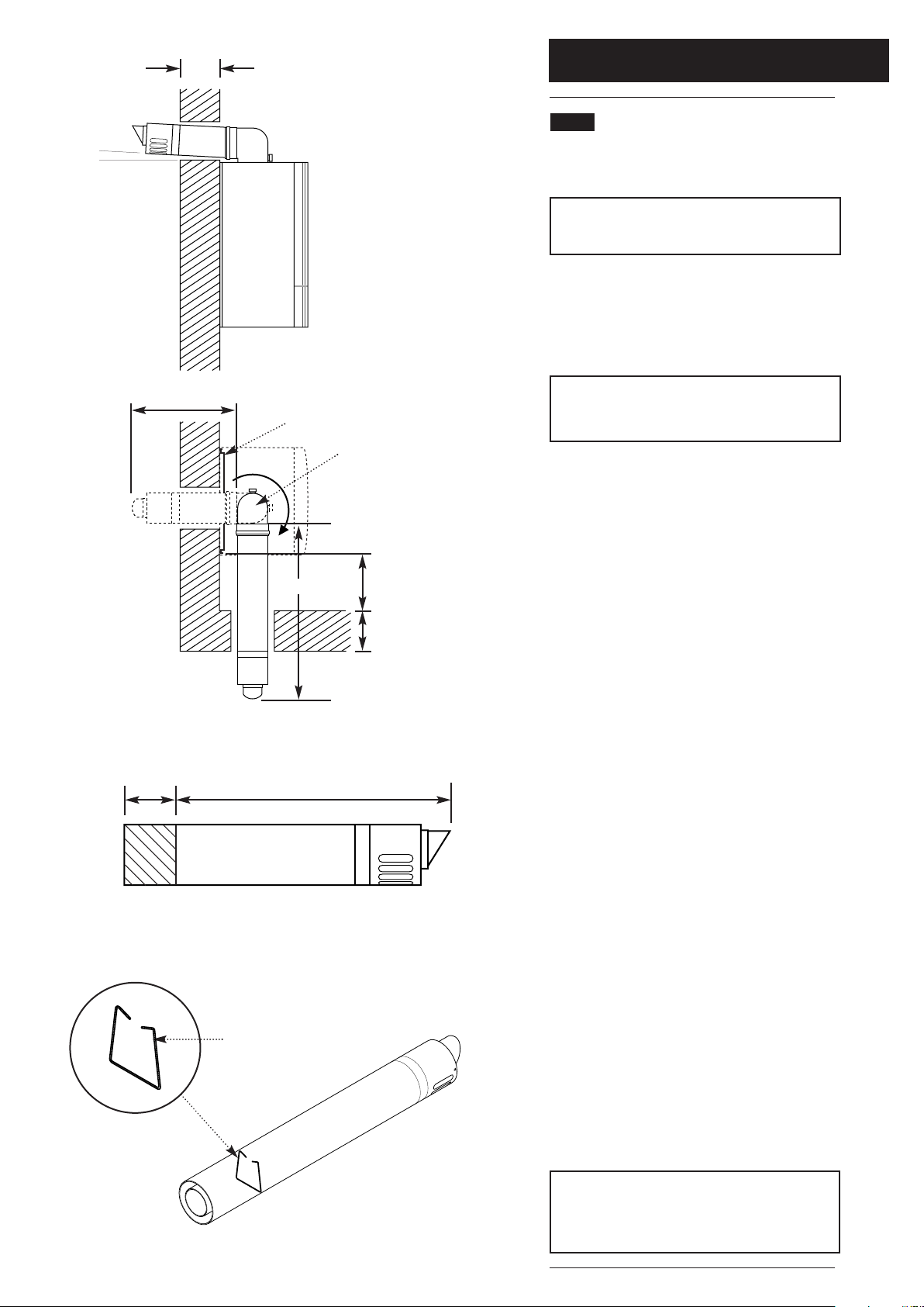
8.6 Fitting The Flue
Before fitting the flue, check the condensate drain
integrity (see section 8.5).
IMPORTANT: The flue should always be installed
with a 3° (1 in 20) fall from terminal to elbow, to
allow condensate to run back to the boiler.
HORIZONTAL FLUE
1. The standard flue is suitable for lengths 270mm
minimum to 800mm maximum (measured from the edge
of the flue elbow outlet).
Rear Flue: maximum wall thickness - 614mm
Side Flue: maximum wall thickness - Right Hand 462mm,
Left Hand 537mm when installed with minimum side clearances of
5mm.
2. For rear exit - measure the wall thickness
(Fig. 21) and to this dimension add 201mm. This
dimension to be known as (X).
i.e. (X) = wall thickness + 201mm
3. Take the flue and mark off (X) from the terminal end
as indicated in the diagram (Fig. 22).
Check your dimensions.
The flue tubes are fixed together. Cut through both tubes
whilst resting the flue on the semi-circular packing pieces.
Deburr both tube ends.
4. For left hand exit - measure the distance from the
edge of the support bracket to the inner face of the wall
(Fig. 21) and to this dimension add the wall thickness +
268mm. This dimension to be known as (Y).
i.e. (Y) = support bracket to wall + wall thickness +
268mm
5. Take the flue and mark off (Y) from the terminal end
as indicated (Fig. 22).
6. For right hand exit - measure the distance from the
edge of the support bracket to the inner face of the wall
and to this dimension add the wall thickness + 343mm.
This dimension to be known as (Z).
i.e. (Z) = support bracket to wall + wall thickness +
343mm
7. Take the flue and mark off (Z) from the terminal end
as indicated (Fig. 22).
Check your dimensions.
The flue tubes are fixed together. Cut through both tubes
whilst resting the flue on the semi-circular packing pieces.
Deburr both tube ends.
IMPORTANT: Check all measurements before
cutting. When cutting ensure the cut does not
interfere with the inner flue support bracket
(Fig. 23).
360° Orientation
Inner Flue Support Bracket
Wall Thickness
Y
Edge of Support Bracket to
Wall
Wall Thickness
(Y) = Left Exit
(Z) = Right Exit
(X) = Rear Exit
Flue
Waste
Fig. 21
Fig. 22
Fig. 23
3°
(1 in 20)
X
Support Bracket
Page 26
8.0 Installation
26
© Baxi Heating UK Limited 2005
8.6 Fitting the Flue (Cont)
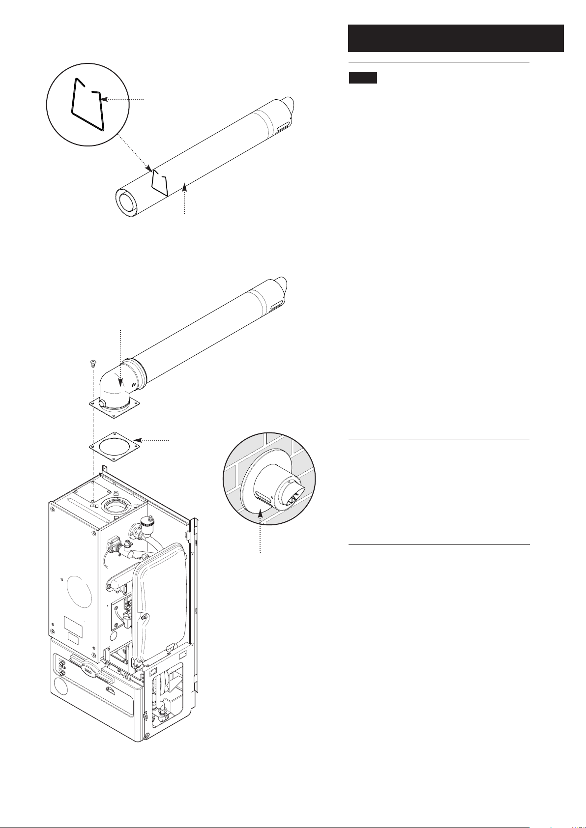
8. Ensure the inner flue support bracket is positioned in
the flue (Fig. 24).
9. Engage the flue into the flue elbow using soap
solution to ease the engagement ensuring the flue is
assembled as shown (Fig. 25).
10. Place the gasket over the flue exit on the boiler
(Fig. 25).
11. Slide the flue assembly through the hole in the wall.
Ensure angled inner end slopes downwards (Fig. 26).
12. Engage the elbow on to the flue connection on top
of the boiler. Secure with the four screws supplied in
the kit.
13. Make good between the wall and air duct outside
the building ensuring the 3° drop between the terminal
and elbow.
14. The flue trim should be fitted once the installation
is complete and the flue secure
(Fig. 26). Apply a suitable mastic to the inside of the
trim and press against the wall finish, making sure the
brickwork is dust free and dry.
15. If necessary fit a terminal guard (see Section 7.9).
VERTICAL FLUEING
1. Only a flue approved with the Baxi Combi HE Plus
Boiler Range can be used.
2. For information on vertical flues consult the Baxi
Flue Guide Brochure or Notes for Guidance supplied
with the vertical flue pack.
Gasket
Flue Trim
Inner Flue Support Bracket
Flue
Flue Elbow
Fig. 24
Fig. 26
Fig. 25
Page 27
8.0 Installation
27
© Baxi Heating UK Limited 2005
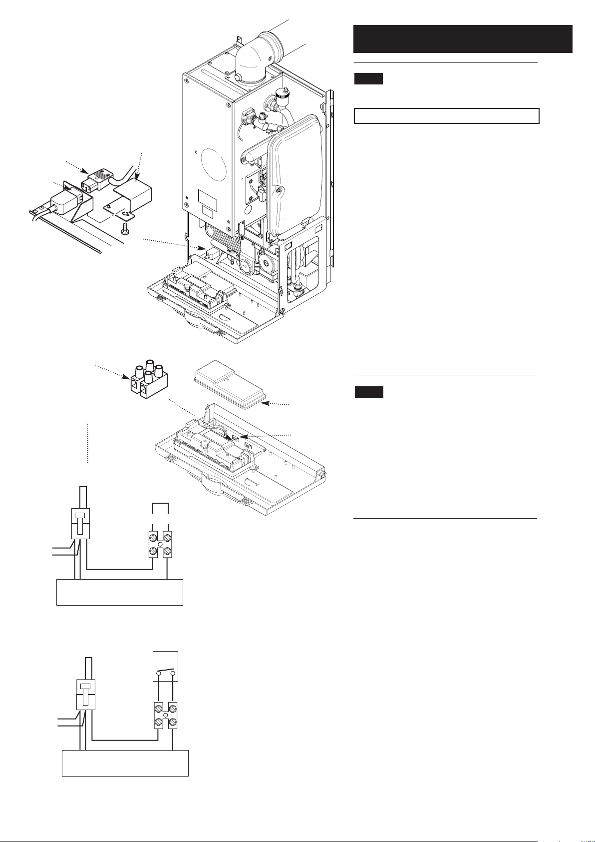
8.7 Making The Electrical Connections
(Fig. 26a)
WARNING: This appliance must be earthed.
1. The electrical connection is on the rear left hand
side of the unit.
2. Remove the electrical plug and lead assembly from
the hardware pack.
3. Connect L, N & E of the lead into the fused double
pole isolator serving the boiler. Connect the plug to
the socket at the back left at the bottom of the boiler.
4. Remove the metal shield from the hardware pack
and connect it over the plug.
5. If fitting an integral timer please refer to the
instructions supplied with the kit.
6. Check the electrical installation for; earth continuity,
short circuits, resistance to earth, correct polarity and
fuse failure (see Section 8.13 Electrical System Checks).
8.8 Connecting an External Timer
1. Undo the screw securing the electrical cover and
remove (133 HE Plus only) (Fig. 27).
2. To connect an external timer switch circuit, remove
the link wire between terminals 1 & 2 and connect the
switch circuit (Figs. 28 & 29).
3. A cable clamp is provided for incoming cables.
Fig. 27
Fig. 28
Fig. 29
Cable Clamp
2-way
Terminal
Block
Link Wire
External Timer
Fig. 26a
Filter
Plug
Metal Shield
Electrical
Cover
1 2
PCB
PCB
For External
Controls
Page 28
8.0 Installation
28
© Baxi Heating UK Limited 2005
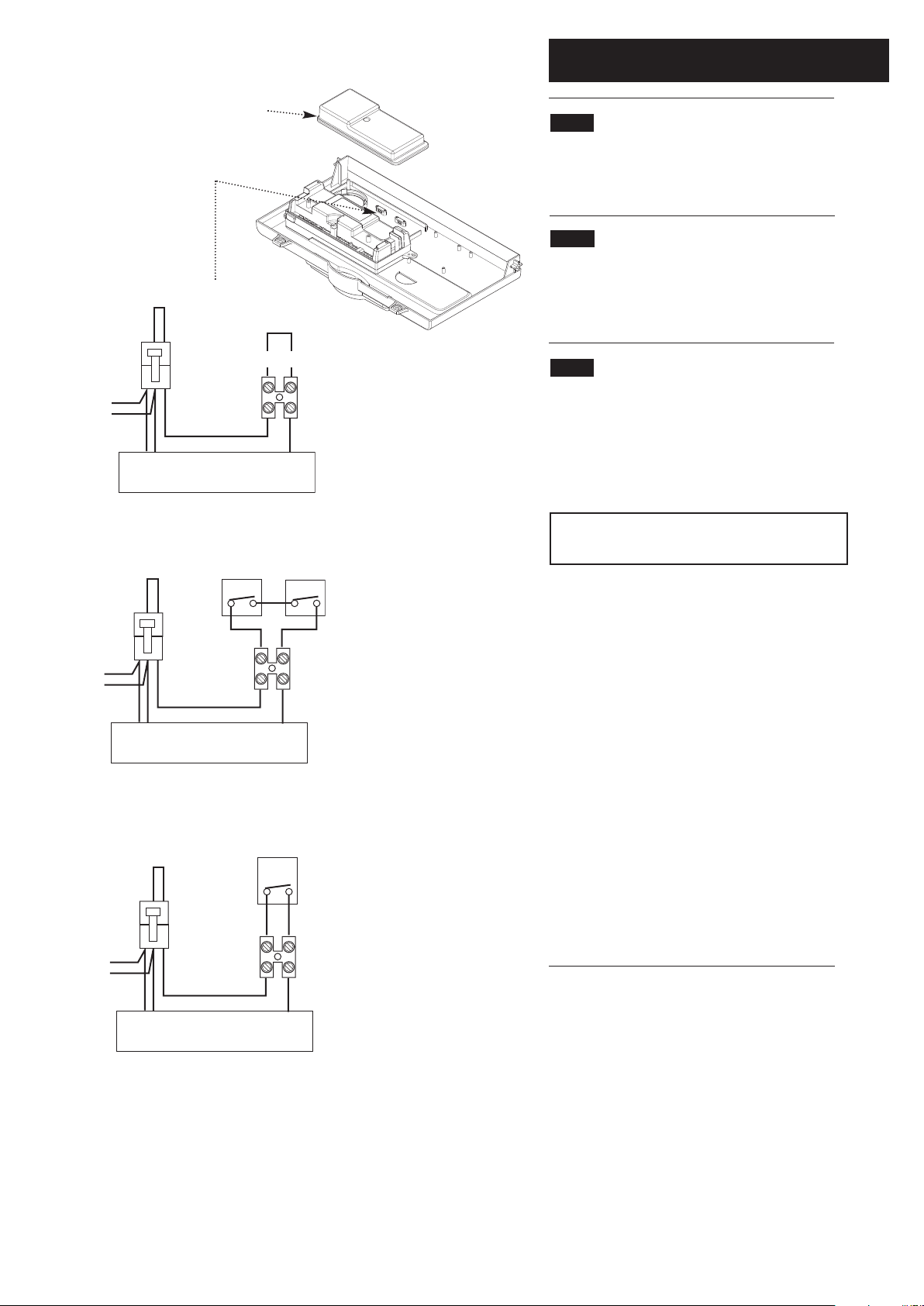
8.9 Fitting a Room Thermostat
1. To fit a 2-wire thermostat, remove link and wire the
thermostat switch between positions 1 & 2 (Figs. 30a).
A cable clamp is provided for incoming cables.
8.10 Fitting a Frost Thermostat
1. The frost thermostat is connected between positions
1 and 2 (Fig. 31) or between mains isolator and position
2. Secure the incoming cable/s with the cable clamp and
replace the cover.
8.11 Electrical System Checks
1. Earth Continuity Check: Isolate the appliance at mains
supply. Using a multimeter set to ohm’s scale, test
between any appliance earth point and the earth pin on
the socket. The resistance should be less than 1ohm. If
the resistance is greater than 1 then check all earth wires
for continuity and ensure that all connections are clean
and tight.
WARNING: If the resistance is still greater
than 1ohm the fault still exists and it could be
dangerous to work with the appliance live.
2. Short Circuit Check: Isolate the control system, set all
switches and thermostats to calling for heat. Set the
meter on ohm’s scale. Test from L to N on control
system terminal block - if the resistance reads zero there
is a short circuit.
3. Resistance to Earth Check: Isolate the control system,
set all switches and thermostats to calling for heat. Set
the meter on ohm’s scale. Test between L and E - the
resistance should be greater than 1 mega ohm.
4. Polarity Check: If all the tests you have carried out so
far are OK, then reconnect the system to the mains
supply. Set the meter on Volts AC scale (starting at the
highest voltage).Test at terminals:
L and N - meter should read approx 240 Vac
L and E - meter should read approx 240 Vac
N and E - meter should read from 0 to 15 Vac
5. Fuse Check: Remove the fuse, check fuse on ohm’s
scale there should be no resistance (infinity) or maximum
reading. If no reading is obtained change the fuse. Check
fuse is 3A.
Fig. 30
Fig. 31
Fig. 30a
External
Timer
Electrical
Cover
Link Wire
1 2
PCB
Room
Thermostat
PCB
PCB
Frost
Thermostat
Page 29
9.0 Electrical
29
© Baxi Heating UK Limited 2005
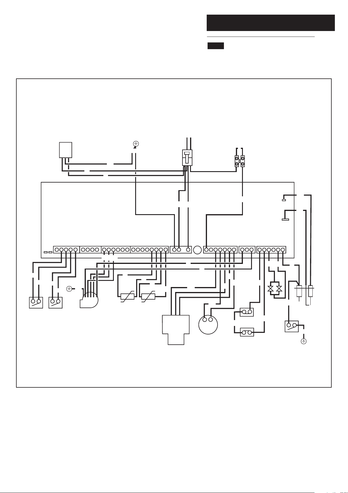
9.1 Schematic Wiring Diagram
Earths not shown to aid
Key To Wiring Colours
b - Blue
bk - Black
gy - Grey
w - White
br - Brown
op - Opaque
r - Red
g - Green
g/y- Green/Yellow
o - Orange
y - Yellow
clarity of diagram
gy
DHW
Flow
Switch
Filter
Mains Input
NL
r
g/y
External Controls
Connection
r
g/y
br
b
w
w
Detection
Electrode
Flame
g/y
op
Spark
Electrode
PCB
g
w
br
b
gy
gy
Switch
CH
Flow
gy
g/y
325 Vdc
DC Fan
Return
Thermistor
b
Flow
Thermistor
r
r
br
b
r
bk
r
b
b
bk
br
br
Thermostat
Flow
Overheat
bk
Gas
Valve
bk
NL
bk
b
o
g/y
Condensate
Tr ap
Diverter
Valve
Pump
Fan
Overheat
Thermostat
Page 30
9.0 Electrical
30
© Baxi Heating UK Limited 2005
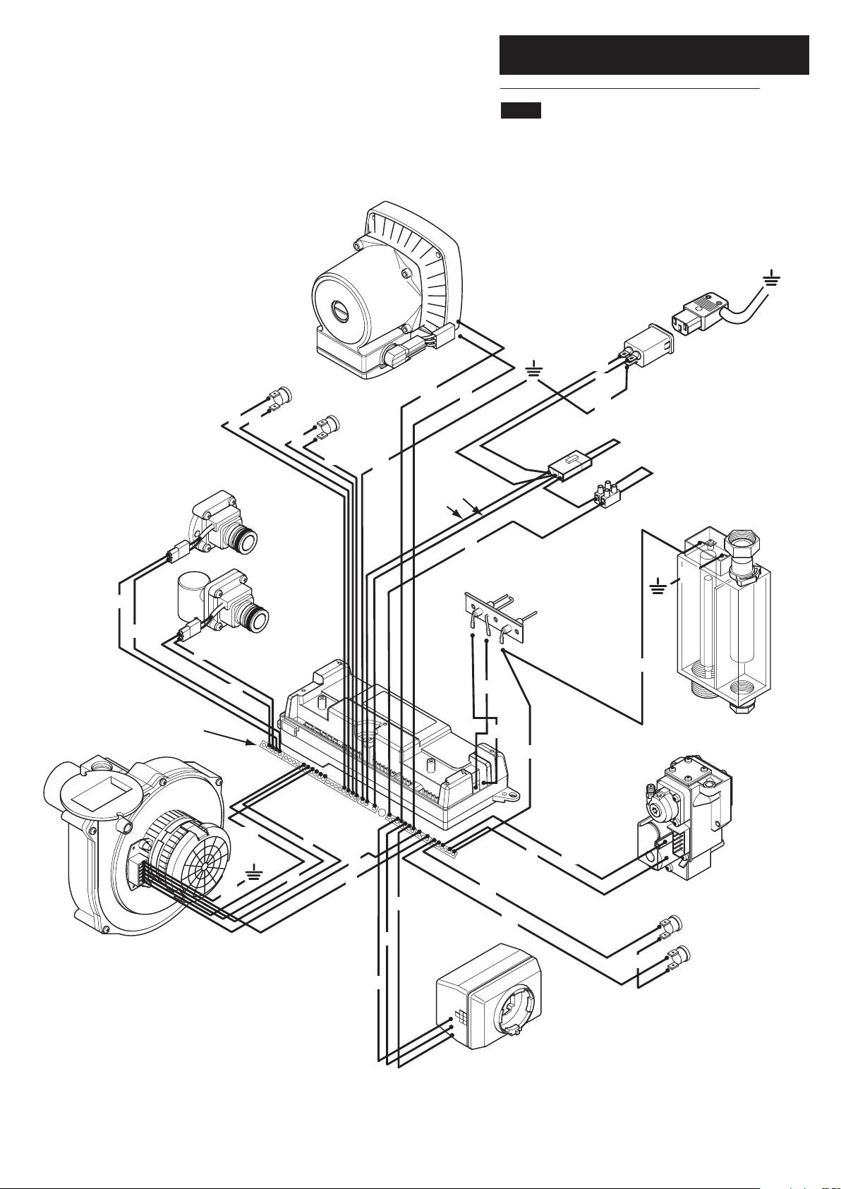
9.2 Illustrated Wiring Diagram
Key To Wiring Colours
b - Blue
bk - Black
gy - Grey
w - White
br - Brown
op - Opaque
r - Red
g - Green
g/y- Green/Yellow
o - Orange
y - Yellow
gy
gy
gy
Return
Thermistor
b
b
CH
Flow Switch
DHW
Flow Switch
gy
Pump
r
Flow
Thermistor
r
g/y
br
Main
PCB
L
N
Plug
br
b
b
g/y
Filter
br
b
o
Spark
Electrode
Flame
Detection
Electrode
g/y
w
g/y
Layout of PCB Pins
Fan
g/y
br
op
Condensate Trap
w
g
r
b
w
r
bk
bk
Gas Valve
b
bk
br
Fan Overheat
Thermostat
bk
bk
Diverter Valve
Flow Overheat
Thermostat
Page 31

10.0 Commissioning the Boiler
31
© Baxi Heating UK Limited 2005
10.1 Commissioning the Boiler
NOTE: The information shown on the display is
explained on the label on the inside of the lower
door panel (see Fig. 38).
1. Open the cold feed to the boiler.
2. Open all hot water taps to purge the Domestic Hot
Water Circuit.
3. Ensure that the filling loop is connected and open, then
open the heating flow and return valves on the boiler
(see Section 10.4 Filling the System).
4. Open the manual and automatic air vents (Fig. 32)
(ensure all external controls are turned on and calling for
heat).
5. The system must be flushed in accordance with BS
7593 (see Section 6.1) and the flushing agent
manufacturers instructions, further guidance can be
obtained from BS 5449 Section 5.
6. Refill the system and add inhibitor following the
inhibitor manufacturer’s instructions. Vent air as described
in Step 4.
7. Complete the label supplied with the inhibitor and
attach to the inside of the boiler case. Detail of system
treatment should be added for future reference.
8. Pressurise the system to 1.5 bar then close and
disconnect the filling loop.
9. Turn the gas supply on and purge according to in GB
BS 6891 and in IE IS 813 "Domestic Gas Installations".
10. Turn the gas service cock anticlockwise to the ON
position and check for gas soundness up to the gas valve.
11. Run the system and check the boiler for correct
operation.
NOTE: These boilers are self-regulating and the gas
rate will vary continously between maximum and
minimum modulation depending on the system or
DHW load. The maximum CH input is factory set
to 26.95kW. This can be increased to 33.7kW on
the 133 and 100 models - see section 10.2.
No adjustment of the gas valve is possible.
12. After a period of 3 minutes and with all the system
controls calling for heat, check the gas pressure at the
inlet tapping of the gas valve (Fig. 34) is greater than
14mbar and the gas rate is no greater than 4.2m
3
/h (133
model) 3.1m
3
/h (100 model) 2.5m3/h (80 model).
WARNING: The PCB Control and Fan
Assembly is 325 Vdc. Isolate at supply before
access.
IN OUT
Automatic Air Vent
Manual Air Vent
Fig. 32
Gas Valve
DO NOT check gas
pressure here
Inlet Gas Pressure Test
Point
Fig. 34
Expansion Vessel
removed for clarity
Page 32
10.0 Commissioning the Boiler
32
© Baxi Heating UK Limited 2005
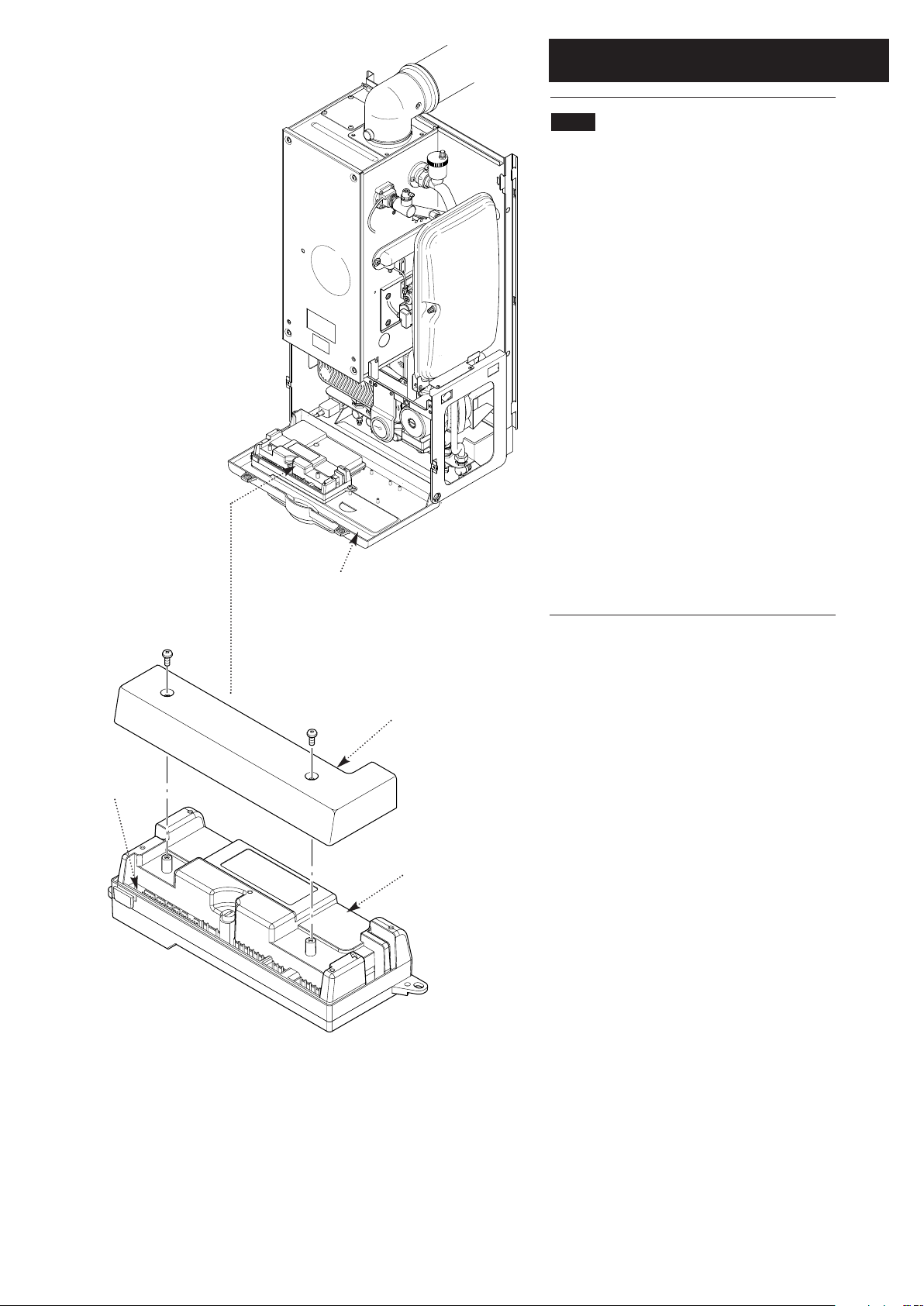
10.2 Increasing Central Heating Output
To 100,000 Btu/hr (Fig. 35)
(Combi 133 & 100 HE Plus only)
1. The boiler is factory set for a maximum output of
80,000 Btu/hr. The boiler will automatically vary its
output to match the system load giving the most
efficient use of gas and the most comfortable room
temperature possible.
2. If the CH system is greater than 80,000 Btu/hr then
to increase the maximum output of the boiler to
100,000 Btu/hr proceed as follows:
a) Isolate the mains supply to the boiler.
b) Remove the outer case.
c) Lower the hinge down facia box.
d) Remove the PCB connection cover.
e) At the extreme left hand side of the PCB there are
two jumpers. Remove the red one labelled CN12.
3. Reassemble in reverse order.
Fig. 35
Remove the Red
Jumper labelled
CN12
Facia Box
PCB
PCB Connection Cover
Page 33
10.0 Commissioning the Boiler
33
© Baxi Heating UK Limited 2005
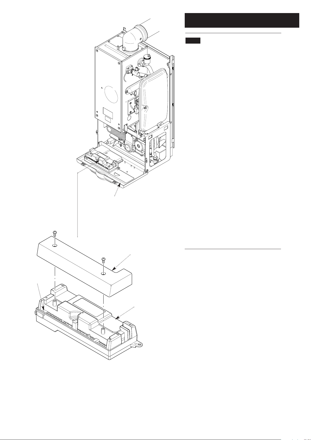
10.3 Switching Off The Intelligent Pre-heat
(Fig. 36)
1. The boiler includes an intelligent pre-heat feature. This
feature ensures that the domestic hot water to the tap is
pre-heated when, and only when, the user required
domestic hot water the previous week. For example, if
the user only requires hot water between 7.00am and
8.00am on Monday then the boiler will log this demand
and then the next week will only pre-heat between
7.00am and 8.00am on Monday. During the first week of
operation from power on no pre-heating will occur.
2. The pre-heat switches the boiler on for approximately
1 minute every 40 minutes whenever it is required.
3. The boiler is factory set with the pre-heat feature on.
If the user wishes to disable this feature then proceed as
follows:
a) Isolate the mains supply to the boiler.
b) Remove the outercase.
c) Lower the hinge down facia box.
d) Remove the PCB connections cover.
e) At the the extreme left hand side of the PCB there
are two jumpers (one Blue, one Red). Remove both
Blue and Red jumpers.
4. Reassemble in reverse order.
Facia Box
Fig. 36
Remove the Blue &
Red Jumpers
labelled
CN11 & CN12
PCB
PCB Connection Cover
Page 34

10.0 Commissioning the Boiler
34
© Baxi Heating UK Limited 2005
10.4
Filling the System
1. When filling the system move the diverter valve to
the central heating position as follows;
a) Ensure that no DHW taps are on.
b) Turn power on to the boiler.
c) Ensure that any external controls are calling for heat.
d) After 10 seconds turn the boiler off at the isolation
switch.
e) The diverter valve will now be in the central heating
position. There is no need to reset the position of the
diverter valve after filling.
Page 35
11.0 Fitting the Outer Case
35
© Baxi Heating UK Limited 2005
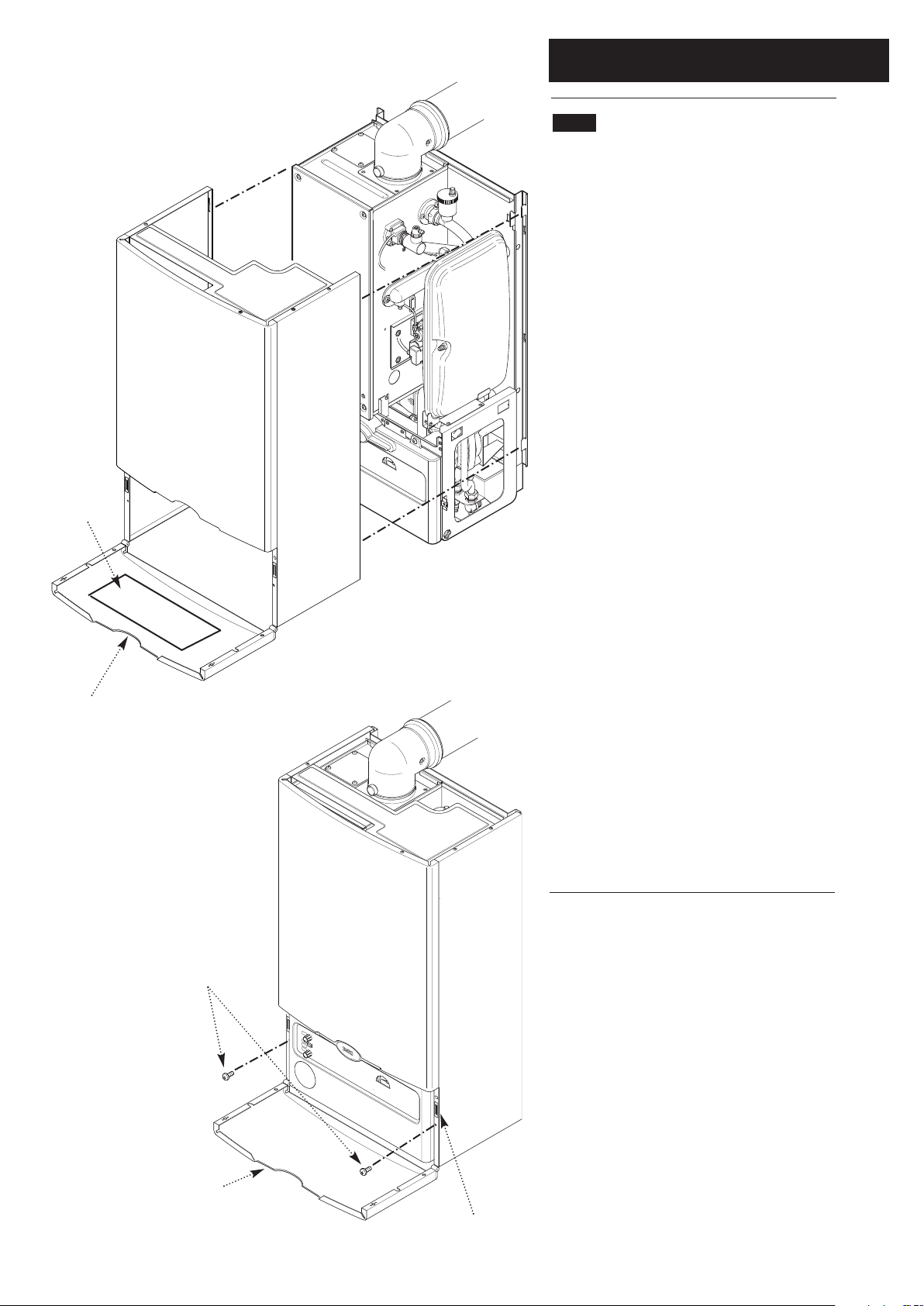
11.1 Fitting The Outer Case
1. Fit the outercase to the appliance ensuring that the
four slots in the side flanges align with the hooks on
the chassis (Fig. 38).
2. Insert the two fixing screws into the sides of the
chassis (Fig. 39).
3. Close the lower door panel against the retaining
magnets (Fig. 39).
4. Instruct the user in the operation of the boiler
controls. Hand over both the Users Operating and
Installation and Servicing Instructions, giving advice on
the necessity of regular servicing.
5. Advise the user that a plume of vapour from the
flue terminal is normal, and that there is no need for
concern.
6. Advise the user that if intelligent pre-heat is on, pre-
heating will not occur for the first week of operation.
7. Set the User preferences. See User Label on lower
door panel (Fig. 38) or user’s operating instructions
(set CH/DHW temperatures).
8. Carefully read and complete all sections of the
Benchmark Commissioning Checklist at the rear of this
publication that are relevant to the appliance and
installation. These details will be required in the event
of any warranty work. The publication must be handed
to the User for safe keeping and each subsequent
regular service visit recorded.
9. For IE, it is necessary to complete a “Declaration of
Conformity” to indicate compliance to I.S. 813. An
example of this is given in I.S. 813 “Domestic Gas
Installations”. This is in addition to the Benchmark
Commissioning Checklist.
Fig. 38
Fig. 39
Lower Door Panel
Outercase Fixing Screws
Lower Door Panel
Retaining Magnet
User
Label
Page 36
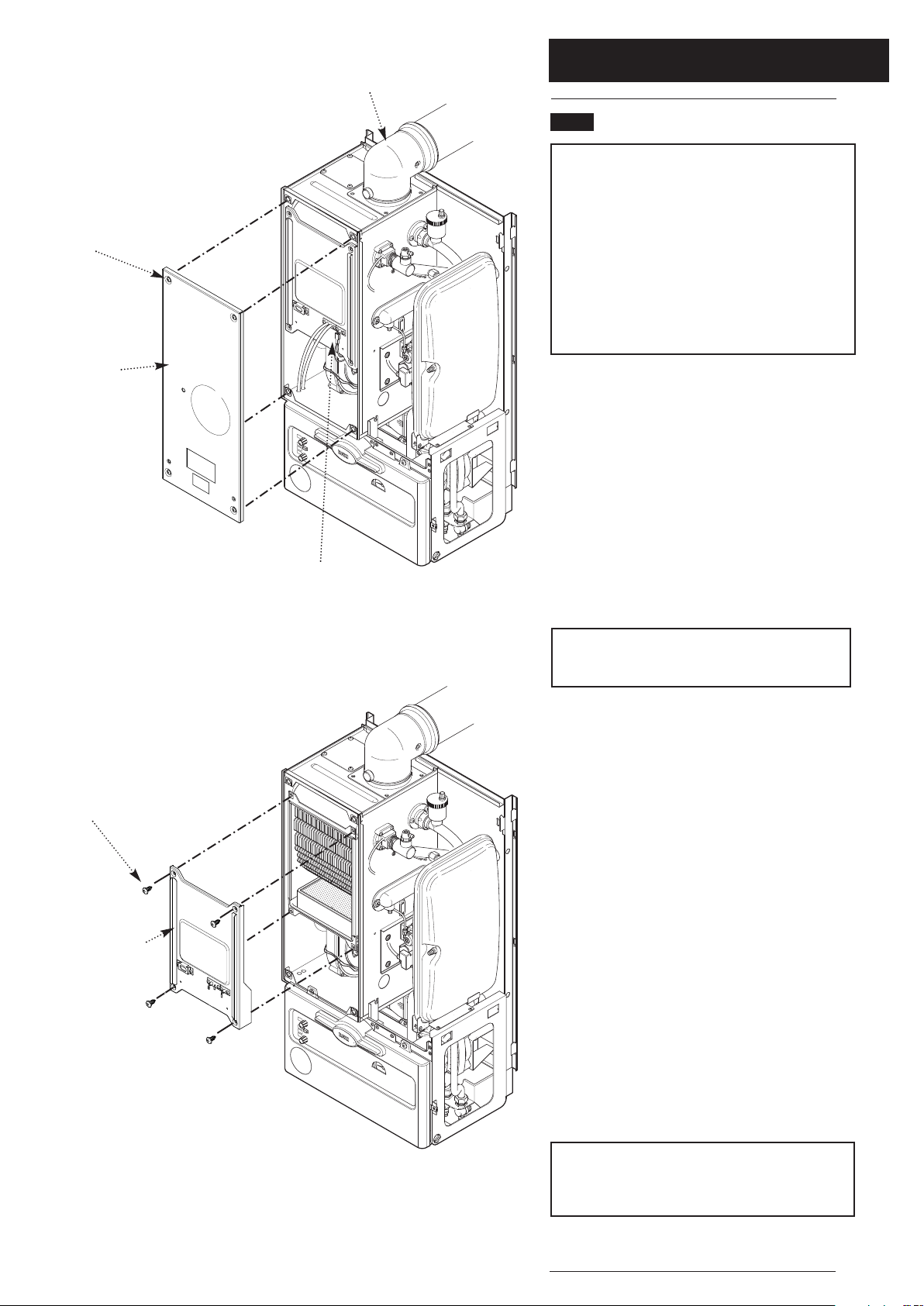
12.0 Servicing the Boiler
36
© Baxi Heating UK Limited 2005
12.1 Annual Servicing
IMPORTANT: When servicing ensure that both the gas
and electrical supplies to the boiler are isolated before
any work is started.
“The boiler cannot be switched off at the boiler,
therefore it is important to isolate the electrical supply at
the mains fuse.”
Hazardous materials are not used in the construction of
Baxi products, however reasonable care during service is
recommended.
When replacing the combustion box door after servicing
it is essential that the retaining screws are tightened fully.
1. For reasons of safety and economy, it is recommended
that the boiler is serviced annually. Before servicing please
read Section 1.2 Important Information.
2. After servicing, complete the relevant Service Interval
Record section of the Benchmark Commissioning
Checklist at the rear of this publication.
3. Ensure that the boiler is cool.
4. Ensure that both the gas and electrical supplies to the
boiler are isolated.
5. Remove the outercase and lower door panel (see
Fitting the Outercase, Section 11.0 in reverse).
WARNING: The PCB Control and Fan
Assembly is 325 Vdc. Isolate at supply before
access.
6. Release the four
1
/4turn screws securing the air box
door panel and remove the door (Fig. 40).
7. Disconnect the three lead terminals from the
combustion box door taking note of their positions
(Fig. 40).
8. Undo the four screws securing the combustion box
door and remove the door (Fig. 41).
9. Visually check for debris/damage and clean or replace if
necessary the following:
a) Burner (Fragile (133 model) - handle with care).
b) Heat exchanger fins.
c) Fan compartment (Check also for condensate leaks).
d) Insulation.
e) Door seals - Important: Pay particular attention to
the condition of the combustion box door seals.
f) Electrodes.
g) The condensate trap must be thoroughly cleaned at
every service (see section 13.24 for removal).
NOTE: If necessary remove the trap drain plug and
place a vessel underneath to catch the condensate
(care should be taken as this could be hot). Clean
the trap and refit the drain plug. Check for leaks.
h) Top of heat exchanger.
NOTE: General cleaning can be undertaken using a
vacuum. However debris should only be gently
blown off the burner skin due to its fragile nature
(133 HE Plus).
10. Check system pressure is between 1 and 2.5 bar.
Flue Elbow
Lead Terminals
Fig. 40
Air Box
Door Panel
Fig. 41
Combustion Box
Door Panel
Combustion Box
Door Securing
Screw
1
/4Turn
Screw
Page 37
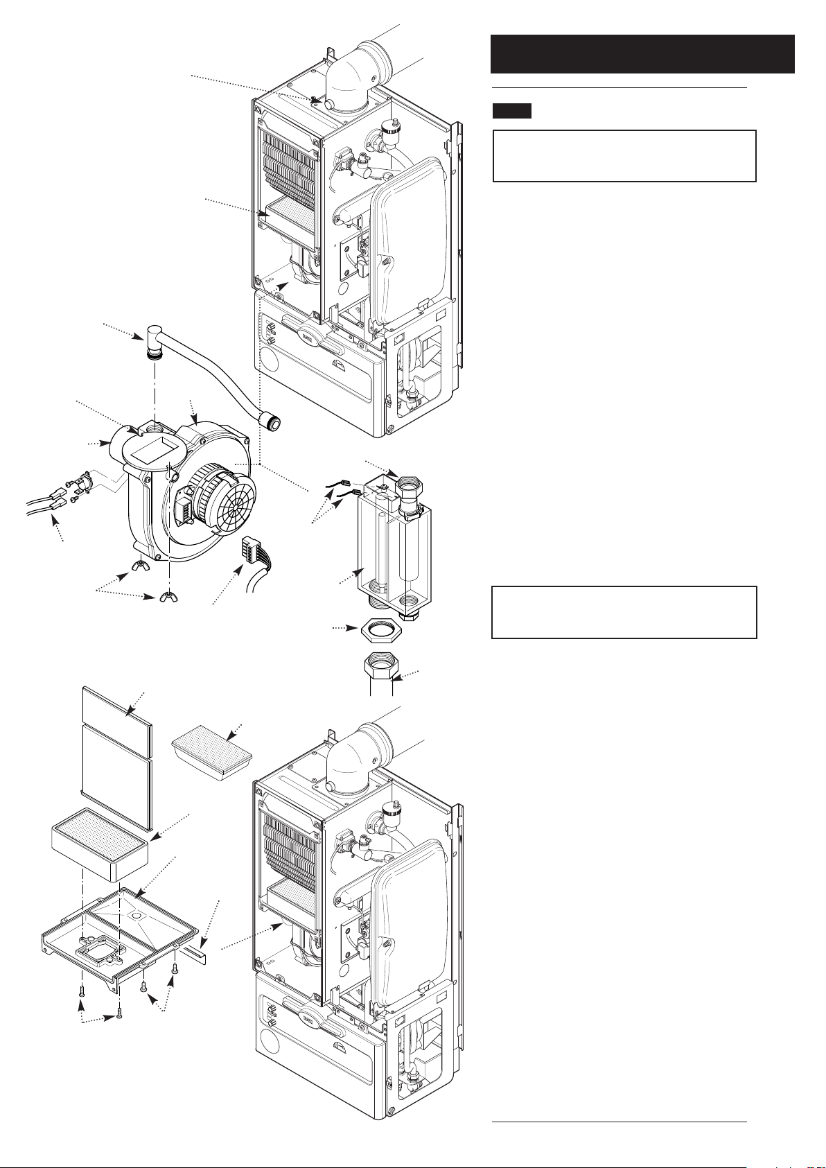
12.0 Servicing the Boiler
37
© Baxi Heating UK Limited 2005
12.1 Annual Servicing (Cont)
NOTE: The information shown on the display is
explained on the label on the inside of the lower
door panel (see Fig. 38).
11. To clean the heat exchanger and burner proceed as
follows:
a) Disconnect the electrical leads to the fan component
protection sensor (Fig. 42).
b) Loosen the screw retaining the gas injector pipe at the
venturi (100 & 80 HE Plus models)
c) Undo the two wing nuts to disconnect the fan
(Fig. 42).
d) Remove the fan and disconnect the electrical supply to
it (Fig. 42).
e) Remove the gas injector pipe from the gas valve (pushfit) (Fig. 42).
f) Undo the condensate trap securing nut, lock nut and
the condensate drain pipe. Remove the condensate trap
and disconnect the sensor leads (Fig. 43).
g) Remove the two screws securing the burner and
remove the burner. Visually inspect the internal burner
baffle for obstruction (Fig. 44).
NOTE: The 133 HE Plus burner skin is fragile handle with care. Clean and if necessary replace the
burner (Fig. 44).
h) Loosen the two screws retaining the heat exchanger
support bracket and slide to the left to remove (Fig. 44).
i) Remove the four screws securing the heat
exchanger/combustion box base and withdraw the base.
j) Lower the central insulation panels and check condition
(Fig. 44). Replace the insulation pads if necessary.
k) Ensure the heat exchanger fins are clear of any
obstruction, use a thin bladed tool to remove debris. The
use of a torch at the heat exchanger top and a mirror
held under the heat exchanger will aid observation of the
heat exchanger fins.
l) Check condition of all seals. Important: Pay particular
attention to the condition of the combustion box door
seals.
m) Reassemble in reverse order, applying a suitable silicon
based grease to “O” rings and seals - Greasil 4000
(Approved Silicone Grease).
12. Check CO/CO
2
ratio at flue sampling point (Fig. 41a).
See section 4.0.
13. Complete the relevant Service Interval Record section
of the Benchmark Commissioning Checklist at the rear of
this publication and then hand it back to the user.
Fig. 42
Burner
Fig. 43
Electrical Supply
Fig. 44
Wing Nuts
Protection
Sensor
Leads
Fan
Injector Pipe
Securing Nut
Condensate
Trap
Sensor
Leads
Locking Nut
Condensate
Drain Pipe
Central Insulation
Panel
Burner
Combustion
Box Base
Heat Exchanger
Support Bracket
Combustion Box Base
Securing Screws
Burner Securing
Screws
Venturi
Injector Pipe Retaining
Screw (100 & 80 HE
models)
100 & 80 HE
Burner
Fig. 41a
Flue Sampling Point
Page 38
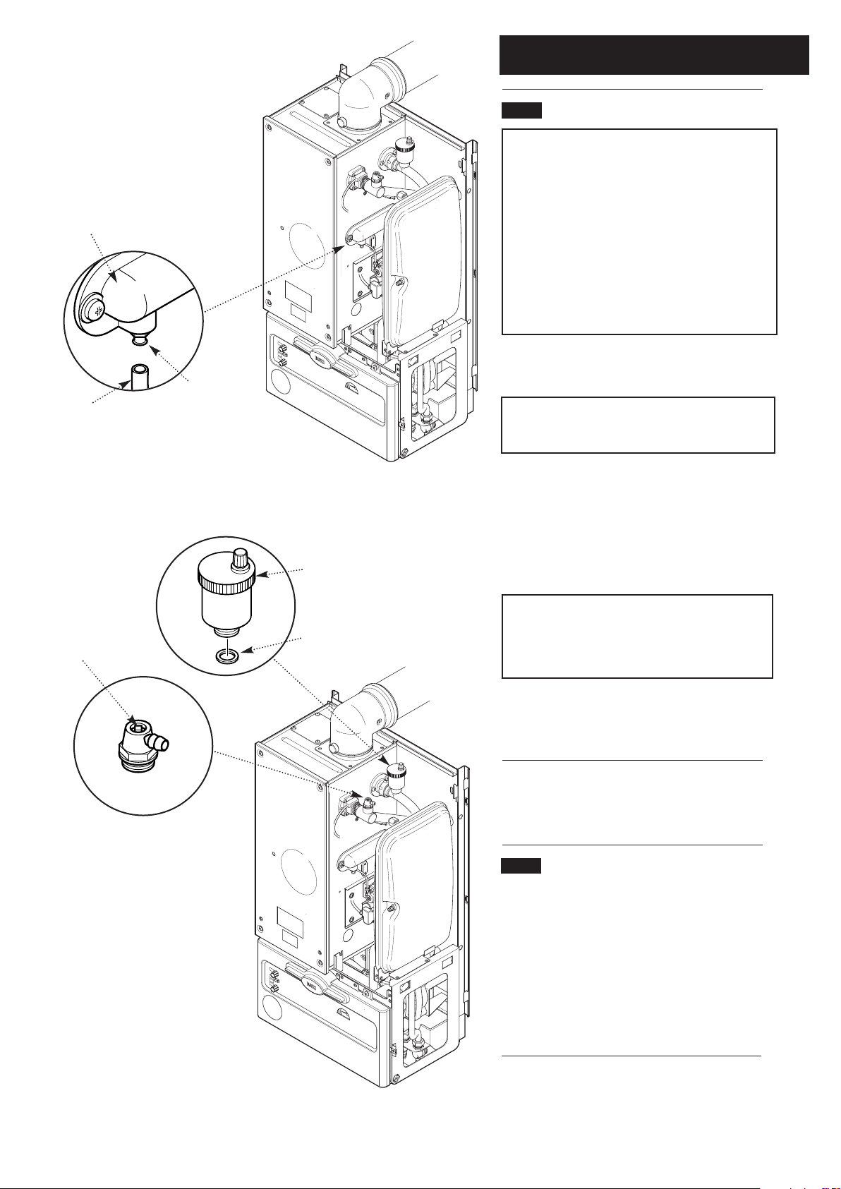
13.0 Changing Components
38
© Baxi Heating UK Limited 2005
13.1 Changing Components
IMPORTANT: When servicing ensure that both the gas
and electrical supplies to the boiler are isolated before
any work is started.
“The boiler cannot be switched off at the boiler,
therefore it is important to isolate the electrical supply
at the mains fuse.”
Hazardous materials are not used in the construction of
Baxi products, however reasonable care during service is
recommended.
When replacing the combustion box door after changing
components, it is essential that the retaining screws are
tightened fully.
1. Remove the outer case and lower door panel (see
“Fitting the Outercase” Section 11.0).
WARNING: The PCB Control and Fan
Assembly is 325 Vdc. Isolate at supply before
access.
2. Isolate the water circuit and drain the system as
necessary. There are 4 drain points:
a) Flow Valve
b) Heat Exchanger Manifold (Fig. 45)
c) Return Valve
d) Cold Water Inlet
NOTE: When reassembling always fit new ‘O’ rings,
ensuring their correct location on the spigot. Green
“O” rings are used for gas joints and Black “O”
rings for water joints. Use Greasil 4000 (Approved
Silicone Grease).
3. After changing a component re-commission the boiler
where appropriate and check the inhibitor concentration
(see Section 6.1 and 10.1).
The air vents, flowswitch, thermistor, safety
thermostat and expansion vessel can be accessed after
removal of the outer case.
13.2 Manual and Automatic Air Vent (Fig. 46)
1. Drain the boiler.
2. Undo the manual air vent from the flow pipe or the
automatic air vent from the return pipe and retain the
sealing washer.
3. Remove the air vent.
4. Fit the new air vent and reassemble in reverse order.
Fig. 45
Heat Exchanger
Manifold
Drain Point
Tube
Fig. 46
Automatic Air
Vent
Sealing Washer
Manual Air Vent
Page 39
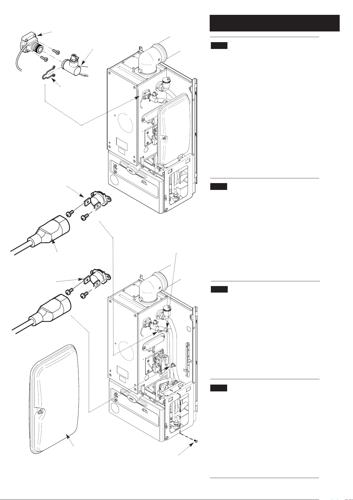
13.0 Changing Components
39
© Baxi Heating UK Limited 2005
13.3 Flowswitch (Fig. 47)
1. Drain the boiler (see Section 13.1 paragraph 2 & 3).
2. It may be necessary to remove the expansion vessel
(see Section 13.5).
3. Remove the clip securing the flow pipe to the
flowswitch.
4. Remove the two screws securing the flow switch to
the boiler.
5. Disconnect the inline electrical connection.
6. Remove the flowswitch.
7. Fit the new flowswitch and reassemble in reverse
order.
8. Recommission the boiler and check the inhibitor
concentration (see Section 6.1 and 10.1).
13.4 Flow or Return Temperature
Thermistors and Safety Thermostat
(Figs. 48 & 49)
1. The procedure is the same for both the thermistors
and the safety thermostat, although the components are
not interchangeable.
2. Remove the electrical connection from the
component.
3. Unscrew the component from the pipe.
4. Fit the new thermistor or safety thermostat and
reassemble in reverse order.
13.5 Expansion Vessel (Fig. 50)
1. Drain the boiler (see Section 13.1 paragraph 2 & 3).
2. Loosen the securing screw at the base of the
expansion vessel.
3. Whilst supporting the vessel undo the expansion
vessel connection and retain the sealing washer.
4. Remove the expansion vessel.
5. Fit the new expansion vessel and reassemble in
reverse order.
13.6 Re-pressuring Expansion vessel
1. The charge pressure is 1.0 bar.
2. Close the central heating flow and return isolating
valves.
3. Drain the boiler (see Section 13.1 paragraph 2 & 3).
4. The “Schraeder” valve is positioned centrally at the
side of the appliance. Pressurise to 1.0 bar.
5. Open the isolating valves and recharge the system to
between 1.0 bar and 2.5 bar. Vent the system as
necessary.
Fig. 47
Flowswitch
Clip
Fig. 48
Fig. 50
Flow Pipe
Electrical
Connections
Expansion Vessel
Expansion Vessel
Securing Screw
Flow Thermistor (Red Body)
Safety Thermostat (Black Body)
Expansion Vessel
Connection
Return Thermistor
(Red Body)
Fig. 49
Page 40
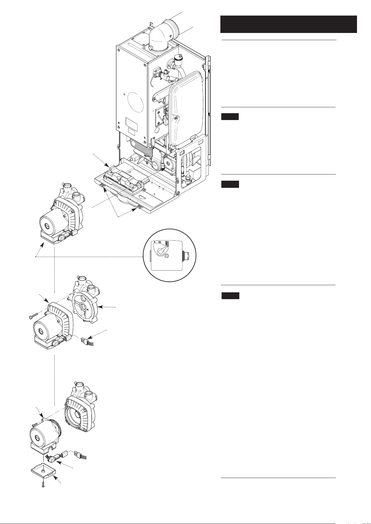
13.0 Changing Components
40
© Baxi Heating UK Limited 2005
The pump, 3-way diverter valve, pressure gauge,
pressure relief valve, plate heat exchanger and DHW
flow switch can be accessed after hinging down the
facia box.
1. Release the facia securing screws (
1
/4turn) and hinge
down the facia box (Fig. 51).
13.7 Pump (Fig. 51)
1. If only the head needs replacing, a standard Grundfos
UPS 15-60 pump head is interchangeable (see section
13.9 for details).
2. This must be switched to setting N
o
3 (Fig. 52).
13.8 Pump (Complete) (Fig. 53)
1. Drain the boiler (see Section 13.1 paragraph 2 & 3).
2. Unplug the wiring harness from the pump.
3. Remove the four screws retaining the pump
backplate to the hydraulic manifold.
NOTE: Ensure nuts are not dislodged.
4. Remove the pump.
5. Fit the new pump and reassemble in reverse order.
13.9 Pump (Head Only) (Fig. 54)
1. Drain the boiler (see Section 13.1 paragraph 2 & 3).
2. Unplug the wiring harness from the pump.
3. Remove the four socket head screws securing the
pump head and separate it from the housing.
4. Remove the screws retaining the pump electrical
covers on the original and replacement heads.
5. From the replacement UPS 15-60 pump head
remove the strain relief cable gland and discard.
6. Remove the plug connector from the old pump head
and wire it into the UPS 15-60 pump head.
7. Replace the electrical cover to the new pump head
and assemble with the electrical box at 6 o’clock to the
housing.
8. Check that the pump has been switched to setting
N
o
3 (Fig. 52) and reconnect the wiring harness plug.
Fig. 51
Facia Box
Fig. 53
Facia Securing Screws
Fig. 52
Pump Setting
Fig. 54
Plug Connector
Hydraulic
Manifold
Wiring
Harness
Pump
Pump
Head
Pump Electrical
Cover
Page 41
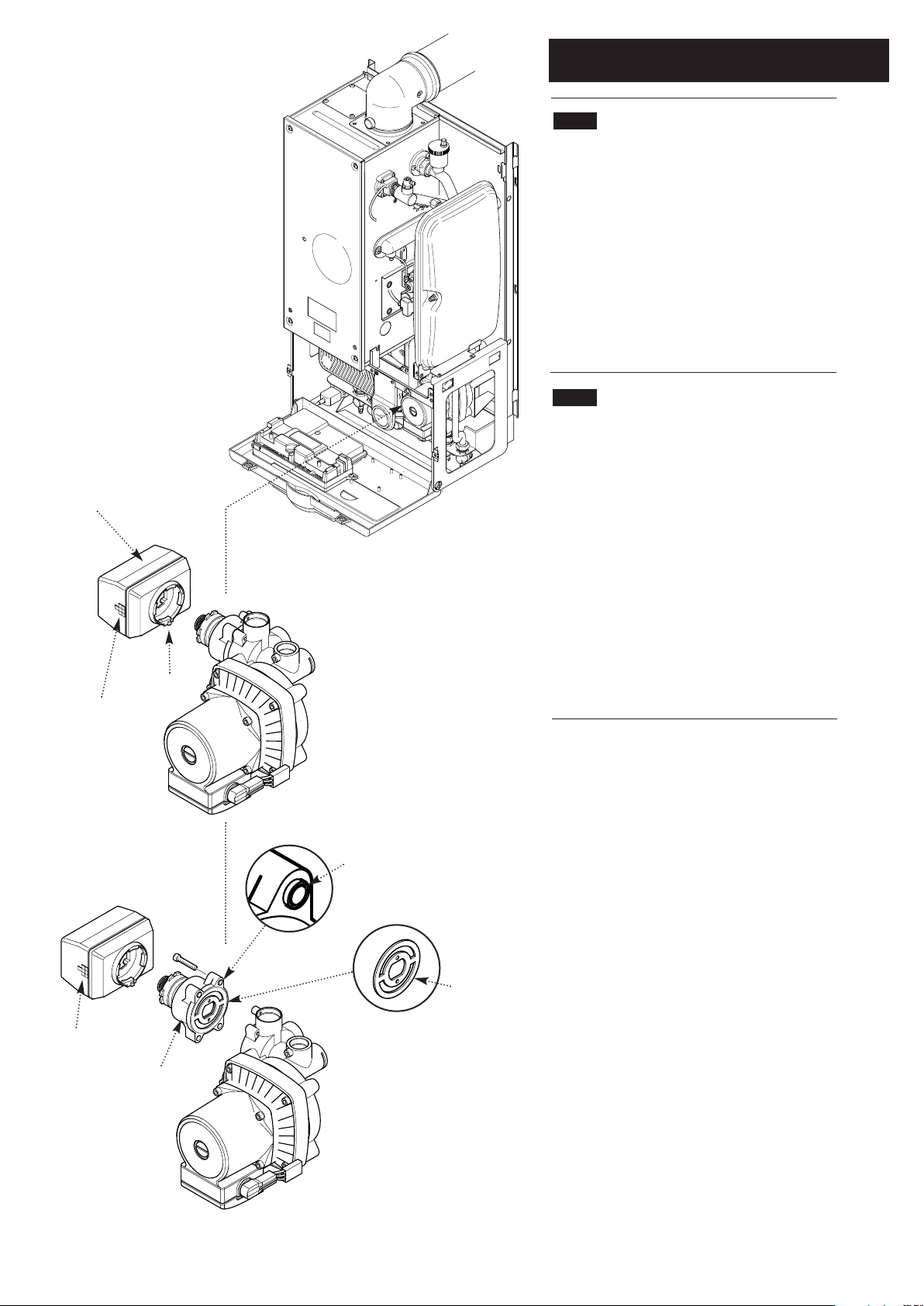
13.0 Changing Components
41
© Baxi Heating UK Limited 2005
13.10 Three-Way Diverter Valve (Head Only)
(Fig. 55)
If only the head needs replacing:
1. Unplug the wiring harness from the 3-way diverter
valve.
2.Depress the clip and revolve the head through 30°
and remove.
3. Fit replacement head and reassemble in reverse
order.
13.11 Three-Way Diverter Valve (Complete)
(Fig. 56)
1. Drain the boiler (see Section 13.1 paragraph 2 & 3).
2. Unplug the wiring harness from the 3-way diverter
valve.
3. Remove the four socket screws retaining the 3-way
valve.
4. Remove the 3-way valve.
5. Fit the new 3-way valve ensuring the gasket is in
place and that the spigots are at the top to fit into the
recesses on the manifold and reassemble in reverse
order.
Fig. 55
Wiring Harness
Fits Here
Fig. 56
Clip
Three-Way
Diverter Valve
Head
Wiring Harness
Fits Here
Three-Way
Diverter Valve
Spigot
Gasket
Page 42
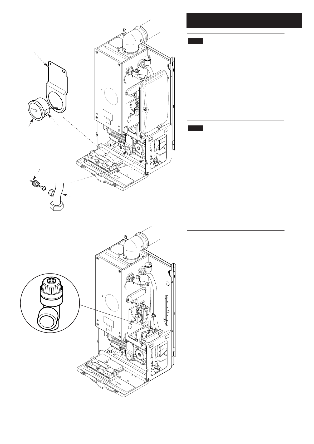
13.0 Changing Components
42
© Baxi Heating UK Limited 2005
13.12 Pressure Gauge (Fig. 57)
1. Drain the boiler (see Section 13.1 paragraph 2 & 3).
2. Undo the nut retaining the capillary in the
connection at the return pipe (Fig. 58).
3. Depress the two lugs on either side of the pressure
gauge and feed through the bracket.
4. Fit new pressure gauge and reassemble in reverse
order.
13.13 Pressure Relief Valve (Fig. 59)
1. The pressure relief valve is positioned on the
hydraulic manifold at the back of the pump.
2. Drain the boiler (see Section 13.1 paragraph 2 & 3).
3. Disconnect the union between the valve and the
discharge pipe.
4. Slacken the screw retaining the valve.
5. Pull the valve upwards to disengage it.
6. Fit the new pressure relief valve and reassemble in
reverse order.
Fig. 57
Lug
Pressure Gauge
Pressure Gauge
Bracket
Fig. 58
Capillary
Return Pipe
Fig. 59
Pressure Relief Valve
Expansion Vessel
removed for clarity
Page 43
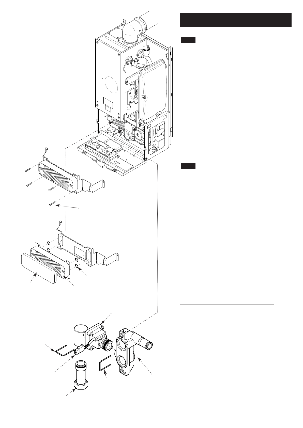
13.0 Changing Components
43
© Baxi Heating UK Limited 2005
13.14 DHW Plate Heat Exchanger
1. Drain the boiler (see Section 13.1 paragraph 2 & 3).
2. Remove the four screws securing the plate heat
exchanger to the manifolds (Fig. 60).
NOTE: Ensure nuts are not dislodged from the
manifolds.
3. Remove the plate heat exchanger cover (Fig. 61)
4. Remove the ’O’ rings from the manifolds and replace
with new ‘O’ rings (Fig. 61).
5. Taking care not to displace the ‘O’ rings fit the new
plate heat exchanger ensuring the nuts are retained in
the manifolds.
6. Refit the plate heat exchanger cover.
13.15 DHW Flow Switch (Fig. 62)
1. Drain the boiler (see Section 13.1 paragraph 2 & 3).
2. Remove the DHW plate heat exchanger (see
section 13.14).
3. Disconnect the inline electrical connection.
4. Remove the clip at right hand side of the flow switch.
5. Undo the DHW inlet connection.
6. Remove the flow switch assembly and undo the
second clip.
7. Fit the new flow switch and reassemble in reverse
order.
8. Ensure that both clips are fully inserted from the
front.
9. Fit the DHW plate heat exchanger.
Fig. 60
Plate Heat Exchanger
Securing Screws
Fig. 61
Plate Heat
Exchanger Cover
‘O’ Rings
Fig. 62
Inline Electrical
Connection
Clip
Flow Switch
Manifold to Pump
Clip
DHW Inlet
Connection
Plate Heat Exchanger
Page 44
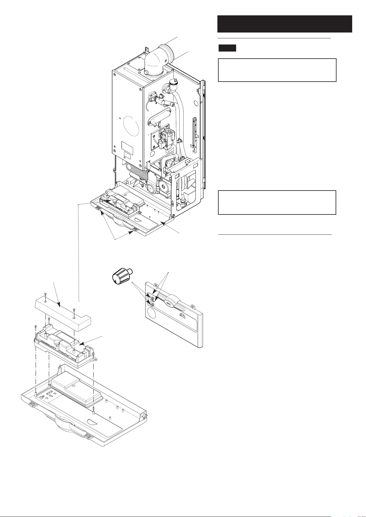
13.0 Changing Components
44
© Baxi Heating UK Limited 2005
13.16 PCB (Fig. 63)
WARNING: The PCB Control and Fan
Assembly is 325 Vdc. Isolate at supply before
access.
1. Pull the control knobs off their spindles and remove
the plastic button covers. Refit them onto the new PCB
(Fig. 63a).
2. Release the facia securing screws (
1
/4turn) and hinge
down the facia box.
3. Remove the screws securing the PCB connection
cover.
4. Remove the screws securing the PCB and disconnect
the electrical connections noting their positions although
they are one way fitting.
NOTE: Check the PCB for the presence of input
jumpers - see section 10.2 & 10.3. Set the new PCB
as the original.
5. Fit the new PCB and reassemble in reverse order.
Fig. 63
Facia Box
Facia Securing Screws
PCB
Control Knob
Fig. 63a
PCB Connection Cover
Plastic Button Covers
Page 45
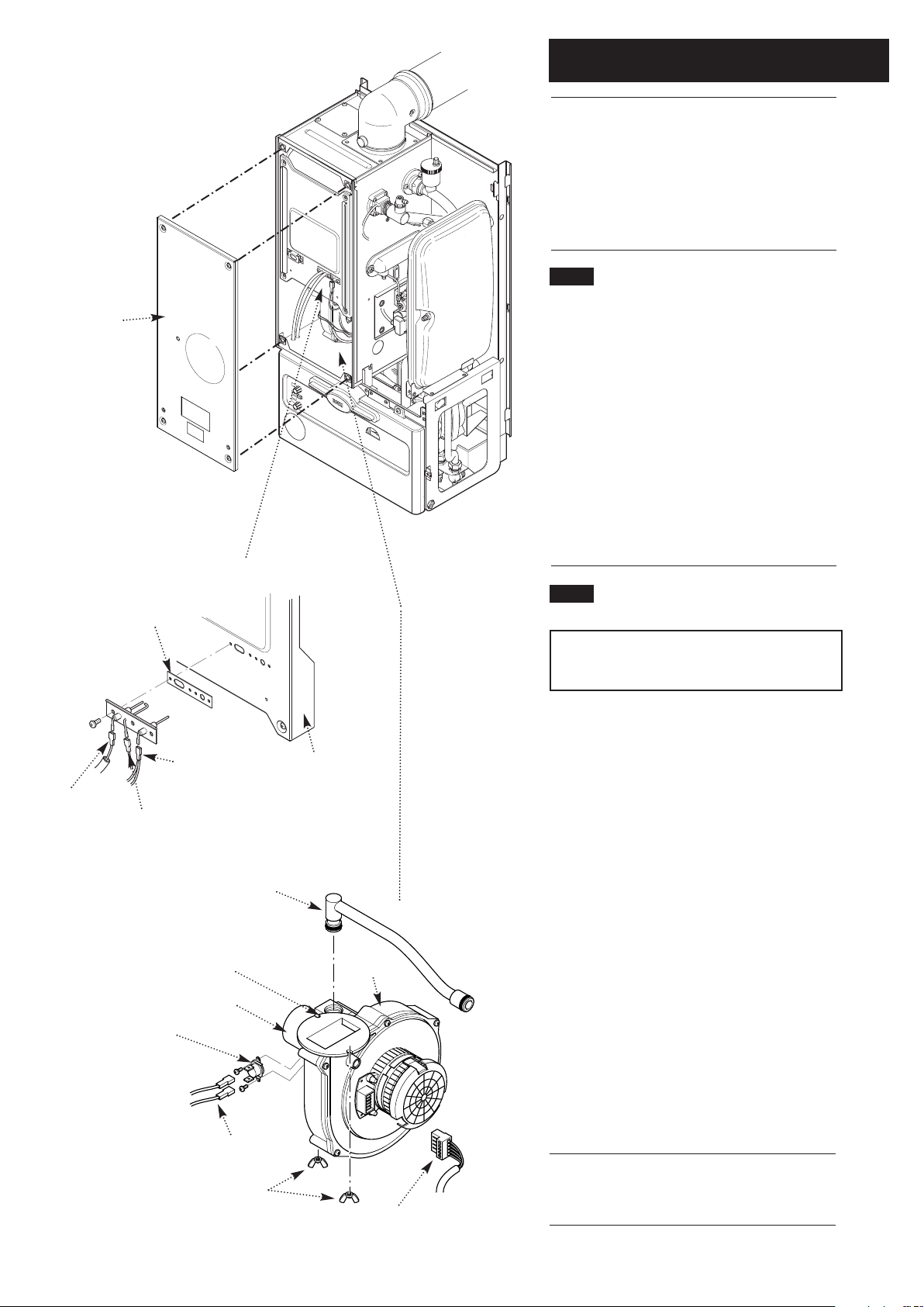
13.0 Changing Components
45
© Baxi Heating UK Limited 2005
The fan and venturi, gas valve, injector pipe,
condensate trap, fan protection thermostat, spark and
sensing electrode can be accessed and changed on the
removal of the airbox door panel.
1. Remove the airbox door panel by loosening the four
1
/4turn screws (Fig. 64).
13.20 Spark and Sensing Electrode
(Fig. 65)
1. Disconnect the leads to the electrode noting their
positions (left to right):
Spark - Opaque Lead
Earth - Green/Yellow Lead
Sensing - White Lead
2. Remove the two screws securing the electrode to the
combustion box door and remove the electrode.
3. Fit the new electrode and new gasket, reassemble in
reverse order, ensuring the spark gap of 3.5mm ±
0.5mm is maintained.
13.21 Fan and Fan Protection Thermostat
(Fig. 66)
WARNING: The PCB Control and Fan
Assembly is 325 Vdc. Isolate at supply before
access.
1. Remove the electrical connections to the fan
protection thermostat on the fan.
2. Replacing the thermostat:- Unscrew the thermostat
and replace with the new thermostat. Reassemble in
reverse order.
3. Replacing the fan:- Remove the wing nuts securing
the fan to the base of the combustion box.
4. Loosen the screw retaining the gas injector pipe at
the venturi (100 & 80 HE Plus models)
5. Lower the fan and disconnect the electrical supply
from the right hand front of the fan. Remove the
fan/venturi assembly.
6. Remove the screws securing the venturi to the fan
and remove the venturi together with the gasket.
7. Remove the fan protection thermostat and fix it to
the new fan, together with the venturi and gasket.
8. Fit the new fan and reassemble in reverse order.
The injector pipe, condensate trap and gas valve can
be changed after the removal of
the fan.
Fig. 64
Air Box Door
Panel
Fig. 65
Fig. 66
Combustion Box
Door
Sensing
Spark
Fan Protection
Thermostat
(Black Body)
Electrical Supply
Wing Nuts
Protection
Thermostat
Leads
Fan
Injector Pipe
Earth
Gasket
Venturi
Injector Pipe Retaining
Screw (100 & 80 HE
models)
Page 46
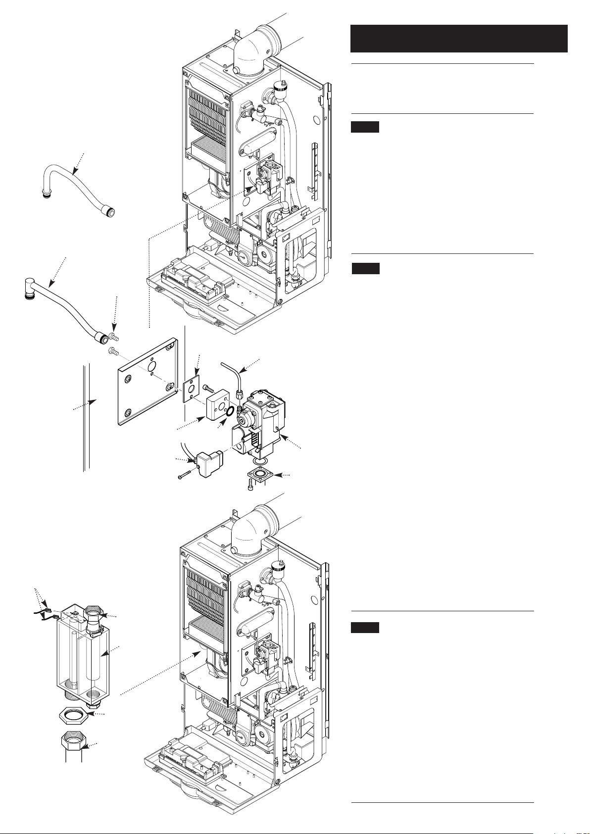
13.0 Changing Components
46
© Baxi Heating UK Limited 2005
It is necessary to remove the fan before changing the
injector pipe, condensate trap and gas valve (see
section 13. 21).
13.22 Injector Pipe (Fig. 67)
1. Loosen the screw retaining the gas injector pipe at
the venturi (100 & 80 HE Plus models)
2. Remove the injector pipe by pulling out from the ‘O’
ring joint in the gas valve.
3. Fit the new injector pipe and reassemble in reverse
order, applying Greasil 4000 (Approved Silicone
Grease) to both “O” rings.
13.23 Gas Valve (Fig. 67)
1. Release the facia securing screws 1/4turn and hinge
down the facia box.
2. Loosen nut at gas inlet pipe at tap rail.
3. Undo the gas pressure pipe from the gas valve.
4. Undo the screw and disconnect the electrical plug
from the gas valve.
5. Remove the two gas valve securing screws from
inside the air box holding the gas valve.
6. Remove the gas valve and inlet pipe from the airbox
side.
7. Remove the four screws securing the gas inlet pipe
to the valve and refit to the new valve.
8. Remove the aluminium spacer and its gasket and
“O” ring from the gas valve.
9. Fit the aluminium spacer, “O” ring and its gasket to
the new valve.
10. Fit the new gas valve and reassemble in reverse
order. Test for gas soundness. NOTE: It is essential that
you ensure gas soundness as they are under negative
pressure.
13.24 Condensate Trap (Fig. 68)
1. Disconnect the condensate trap from the base of the
heat exchanger.
2. Disconnect the condensate drain (outside the boiler)
from the condensate trap.
3. Undo the condensate trap lock nut.
4. Remove the condensate trap from the boiler.
5. Disconnect the sensor leads.
Fit the new condensate trap and reassemble in reverse
order.
Fig. 67
Injector Pipe
Gas Valve Securing
Screws
Boiler Side
Gas Valve
Gasket
Gas Pressure
Pipe
‘O’ Ring
Aluminium
Spacer
Electrical Plug
Gas Inlet Pipe
Flange
Fig. 68
Securing Nut
Condensate Trap
Sensor
Leads
Locknut
Condensate
Drain Pipe
Injector Pipe
(100 & 80 HE models
Page 47
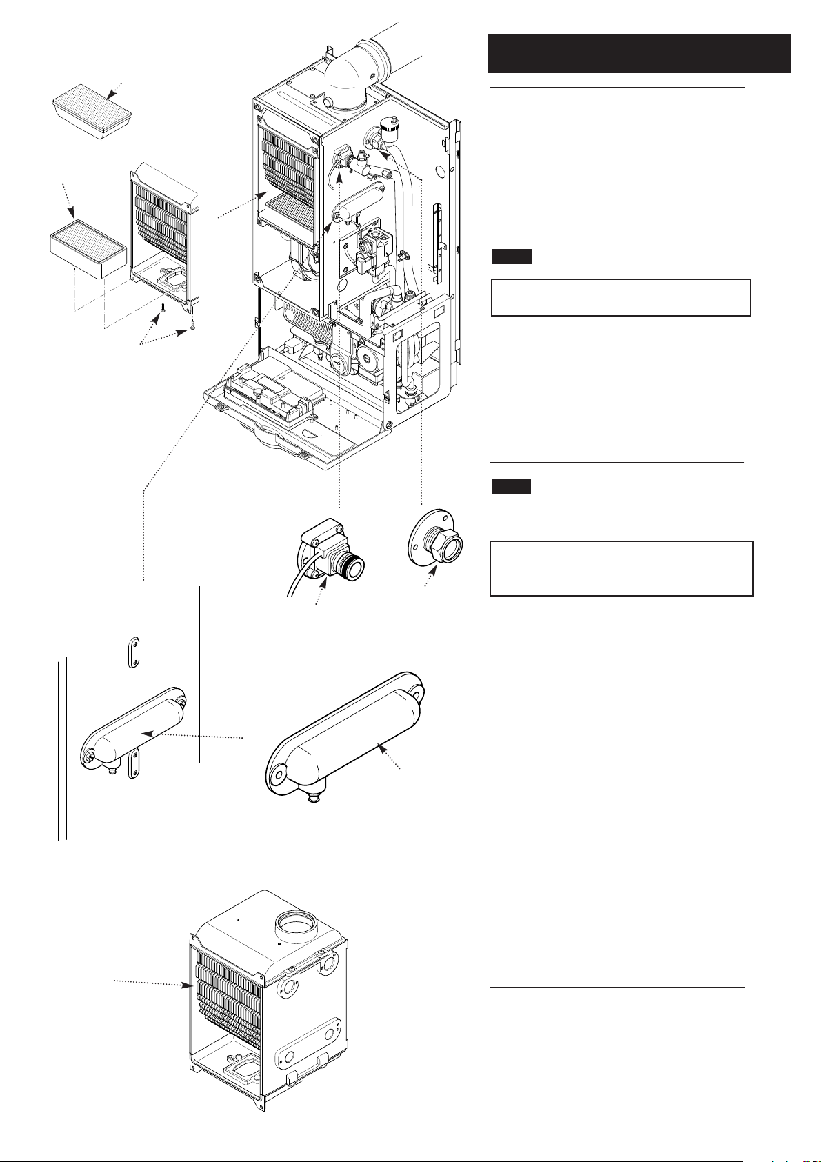
13.0 Changing Components
47
© Baxi Heating UK Limited 2005
The burner and heat exchanger can be changed after
removal of the combustion box door. To change the
heat exchanger, the fan and burner must be removed
first (see section 13. 21 & 13. 25).
1. Remove the combustion box door by undoing the
four
1
/4turn securing screws.
13.25 Burner (Fig. 69)
WARNING: The burner skin is fragile
(133 model): (HANDLE WITH CARE)
1. Remove the two 8mm hex head screws securing the
burner to the base of the combustion box.
2. Remove the burner carefully from the combustion box
base, inspect gasket for damage, replace if necessary.
3. Fit the new burner and reassemble in reverse order.
13.26 Heat Exchanger
1. Drain the boiler (see section 13.1 paragraph 2 & 3).
WARNING: The PCB Control and Fan
Assembly is 325 Vdc. Isolate at supply before
access.
2. Remove the fan and condensate trap (see section
13.21 and 13.24).
3. Undo the screws securing the flow switch and return
connections. Remove the flow switch and return
connection (Fig. 70).
4. Undo the screws securing the heat exchanger manifold
and remove the manifold (Fig. 71).
5. Undo the screws on the bracket supporting the heat
exchanger and remove bracket.
6. Lift the heat exchanger assembly (Fig. 72) and rotate
the bottom upwards whilst pulling it forwards out of the
airbox.
7. Fit the new heat exchanger and reassemble in reverse
order.
8. Recommission the boiler and check the inhibitor
concentration (see Section 6.1 and 10.1).
Fig. 69
Securing
Screws
Fig. 70
Burner
Flow
Switch
Return
Connection
Heat Exchanger
Manifold
Fig. 71
Fig. 72
Heat Exchanger
Assembly
100 & 80 HE
Burner
Page 48
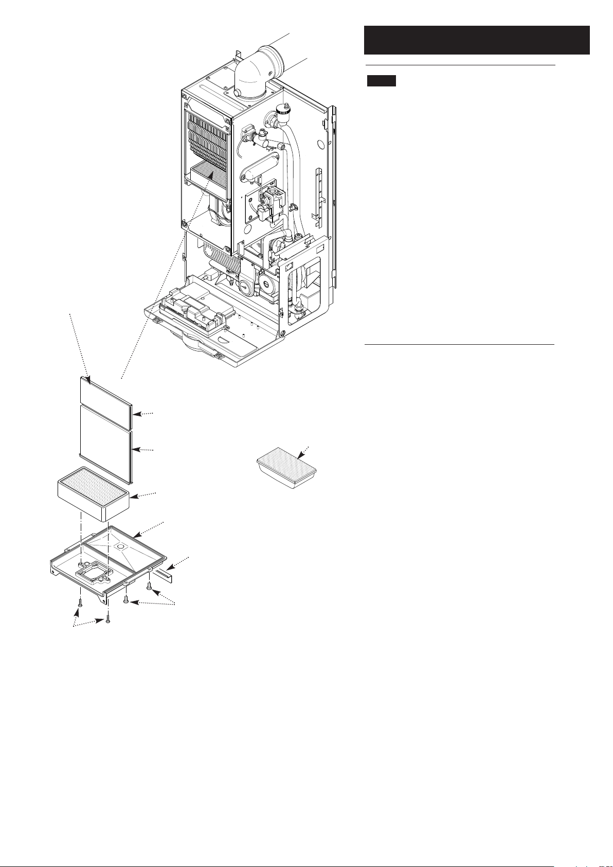
13.0 Changing Components
48
© Baxi Heating UK Limited 2005
13.27 Heat Exchanger Insulation Pads (Fig. 73)
1. Remove the fan and condensate trap (see section
13.21 and 13.24).
2. Remove the burner (see section 13. 25).
3. Remove the four bolts securing the combustion box
base.
4. Remove the combustion box base.
5. Pull the central insulation panel down from the
centre of the heat exchanger and remove the
insulation pads.
6. Check combustion box seal for damage, replace if
necessary.
7. Fit the new insulation pads and reassemble in
reverse order.
Fig. 73
Central Insulation Panel
Lower Insulation Panel
Upper Insulation Panel
Burner
Combustion Box Base
Support Bracket
Burner Securing Screws
Combustion Box Base
Securing Bolts
100 & 80 HE
Burner
Page 49
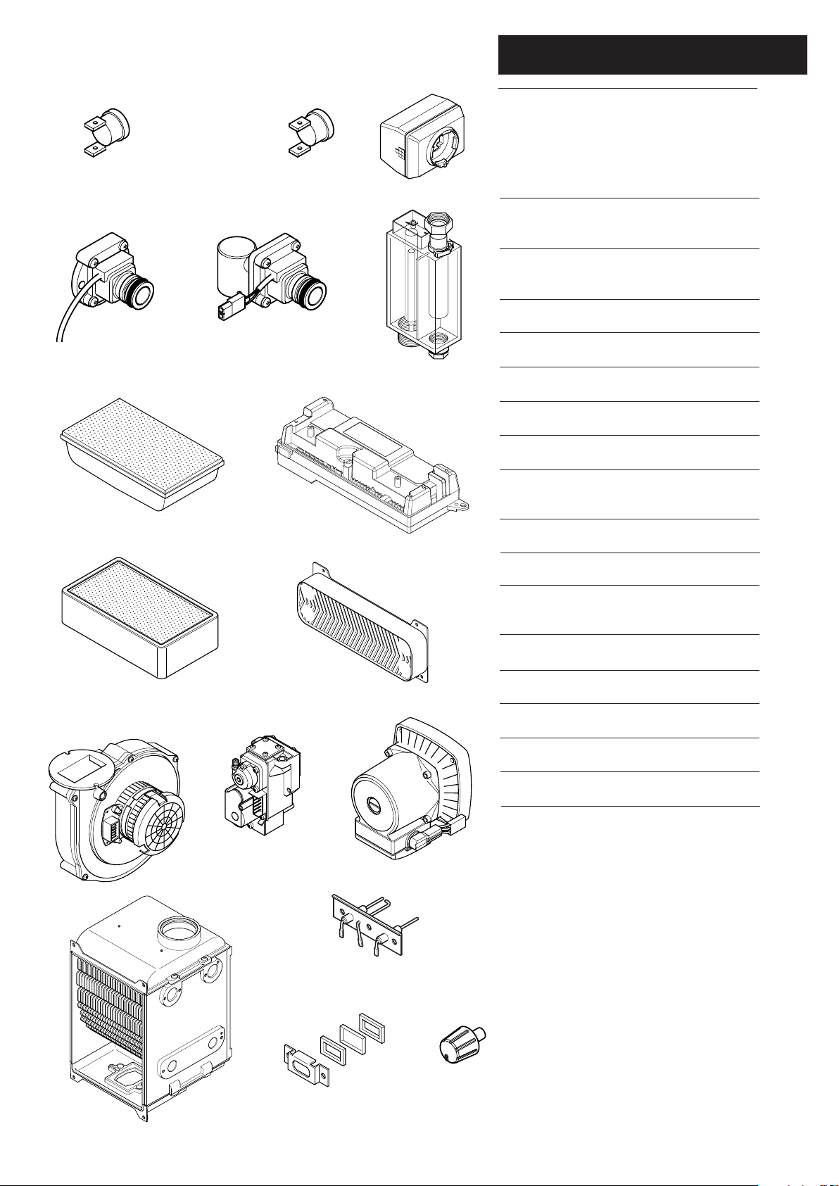
14.0 Short Parts List
49
© Baxi Heating UK Limited 2005
Short Parts List
Key G.C. Description Manufacturers
No. No. Part No.
A E58 933 Flow Thermistor (Red) /
Return Thermistor 240670
C E58 912 Safety Thermostat (Black) /
Fan Protection 242235
D E06 059 Flow Switch Kit 242459
E DHW Flow Switch Kit 247502
G PCB - enclosure 5110991
I Pump 240395
K E58 935 Diverter Valve Head 243341
L Fan (133 HE 5109926
Fan (100 & 80 HE) 5109925
M Condensate Trap Kit 5111714
N E78 749 Gas Valve Kit 247222
O E58 900 Burner (133 HE) 245199
Burner (100 & 80 HE) 5107430
P Electrode Kit 5110992
R Plate Heat Exch. Kit 247224
S E06 085 Inspection Window Assy 242484
T E06 097 Heat Exchanger Assy 242497
U Control Knob 5109996
A
S
C
K
DE
G
I
M
O
N
P
R
L
T
O
U
Page 50
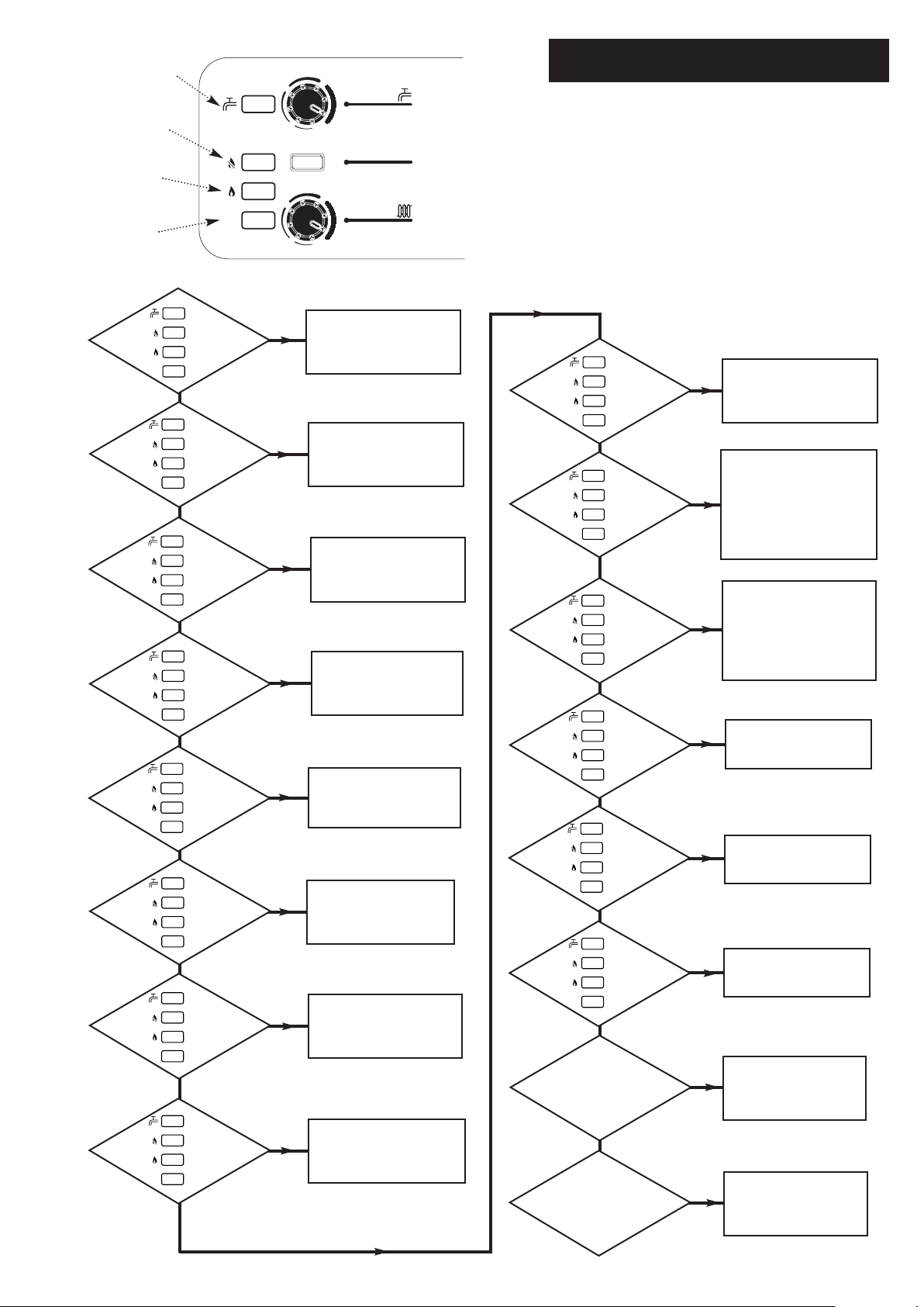
15.0 Fault Finding
50
© Baxi Heating UK Limited 2005
Low Electrical Supply
Incoming Voltage less than
180V. Check System Controls
& System Wiring. Otherwise
contact Electricity Provider.
Live & Neutral Reversed
Incoming Live and Neutral
reversed.
Wiring Harness
Ensure 8-way PCB
connector securely pushed
in. If fault persists replace
Wiring Harness.
Go to Return Thermistor
section of the fault
finding instructions.
Go to Flow Thermistor
section of the fault finding
instructions.
CH works but
DHW does not.
Go to DHW Flow Switch
section of the fault
finding instructions.
DHW works but
CH does not.
Go to DHW Fault
section of the fault finding
instructions.
Go to Fan Lockout
section of the fault finding
instructions.
Go to Ignition Lockout
section of the fault finding
instructions.
Go to Overheat Lockout
section of the fault
finding instructions.
PCB Fault
Replace PCB.
YES
YES
YES
YES
YES
YES
YES
YES
YES
YES
YES
YES
YES
YES
Before performing fault finding carry out
preliminary electrical checks for earth,
continuity and polarity.
See Section 8.13
YES
Go to Electrical Supply
section of the fault finding
instructions.
Domestic Hot Water
LED Light - Green
Burner ON
LED Light - Green
Mains ON
LED Light - Green
Flame Failure
LED Light - Red
Off
Off
Off
Off
ON
LED
Lights
Off
On
Off
Flash
ON
LED
Lights
Go to Dry-Fire
section of the fault finding
instructions.
Off
On
Flash
Flash
ON
LED
Lights
Off
On
Off
On
ON
LED
Lights
Off
Flash
Off
On
ON
LED
Lights
Off
Flash
Flash
On
ON
LED
Lights
On
On
Flash
On
ON
LED
Lights
Off
On
Flash
On
ON
LED
Lights
On
On
Flash
Flash
ON
LED
Lights
Off
Flash
Off
Flash
ON
LED
Lights
Off
On
On
On
ON
LED
Lights
Off
Flash
On
Flash
ON
LED
Lights
PCB Fault
Replace PCB.
PCB Fault
Replace PCB.
Off
On
On
Flash
ON
LED
Lights
Off
Flash
On
On
ON
LED
Lights
Go to CH Fault
section of the fault finding
instructions.
YES
Low
High
Reset
ON
High
Low
Page 51
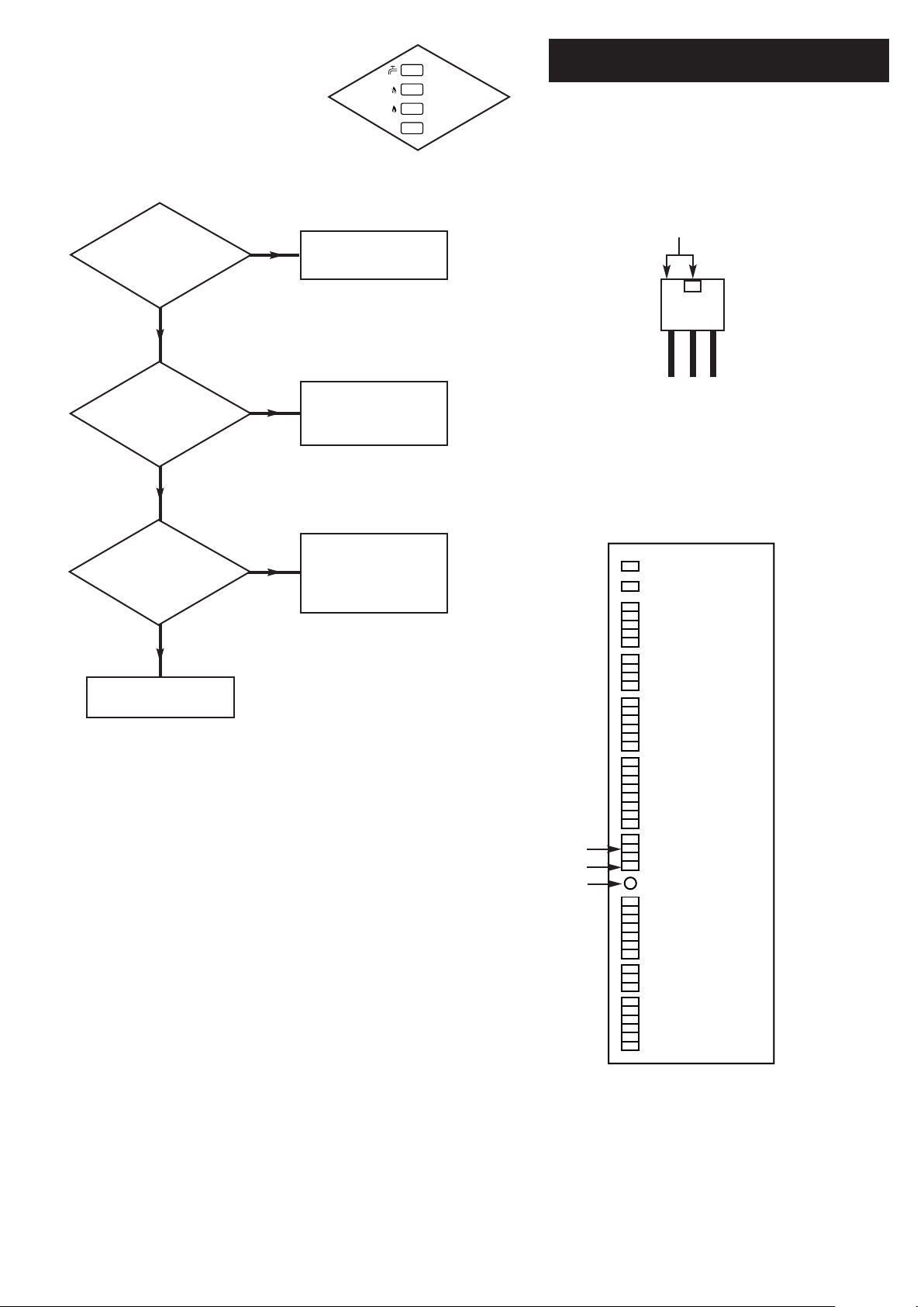
15.0 Fault Finding
51
© Baxi Heating UK Limited 2005
Connect Mains to boiler.
240V at B ?
Check wiring from
terminal block to PCB.
Check for shorts on
pump, fan & gas valve.
Replace if shorted &
replace fuse.
YES
NO
Replace PCB.
YES
YES
NO
NO
ELECTRICAL SUPPLY
240V at A ?
PCB fuse OK ?
B
Fuse
A
Off
Off
Off
Off
ON
LED
Lights
Page 52
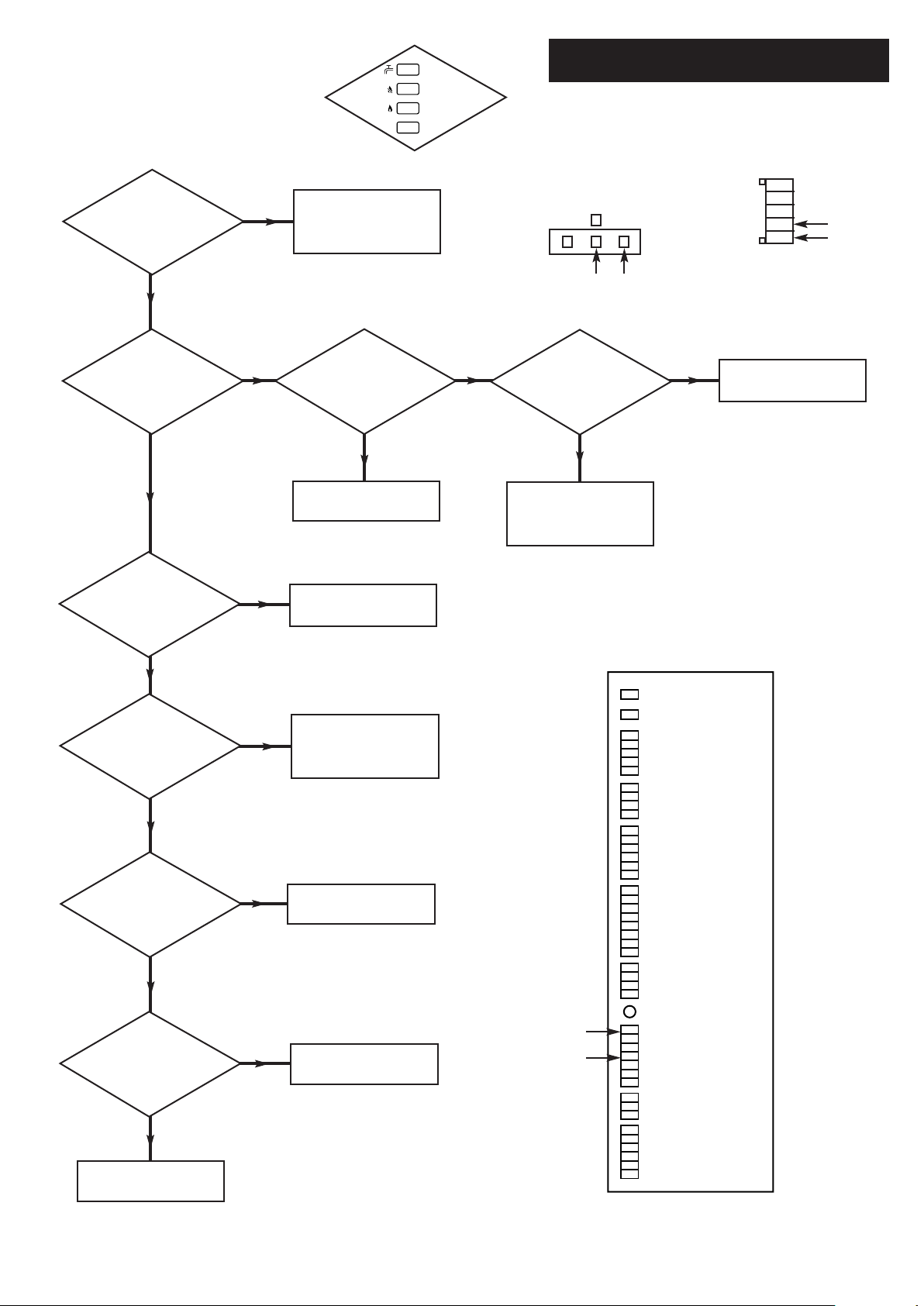
15.0 Fault Finding
52
© Baxi Heating UK Limited 2005
Is
the system
full of water ?
Fill system with water and
bleed out all air.
YES
NO
With
water flowing out
of a fully open DHW tap
does the pump
run ?
Unplug the
pump is there
240V at C ?
Is
there 240V at D ?
Replace PCB.
Wiring from terminal
block to PCB faulty.
Pump fault.
Wires from inline
connector to PCB faulty.
Remove blockage.
YES
YES
NO
NO
NO
NO
YES
YES
YES
NO
YES
Unplug
5-way PCB connector.
With water flowing out of a fully
open DHW tap is there
continuity at
E ?
DRY-FIRE
Replace PCB.
Disconnect
primary flow switch
inline connector, with a tap open
is there continuity
across flow
switch ?
Remove
flow switch from boiler.
Is there a physical blockage to the
paddle within the
flow switch ?
Is
there a blockage in
the system ?
Remove blockage.
NO
Replace flow switch.
NO
YES
E
Viewed from
Wire Entry end
C
Pump Plug
(when unplugged)
D
Off
On
Flash
Flash
ON
LED
Lights
Page 53
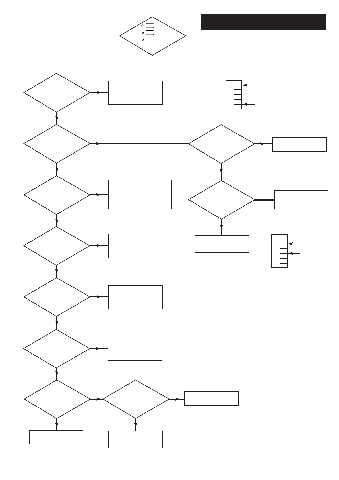
15.0 Fault Finding
53
© Baxi Heating UK Limited 2005
Check isolation valve and
gas supply.
Remove gas valve & check inlet
filter for blockage. Otherwise
incorrect gas supply to boiler.
YES
NO
Ignition Lockout
YES
YES
NO
NO
Is there
gas at gas valve inlet ?
Reset lockout.
Is there gas flow ?
(check at the meter)
Replace spark or flame
detection probe.
Is spark or
flame detection probe
damaged ?
Is there at
least 18mbar dynamic
at gas valve inlet ?
Set spark gap to 3.5mm.
Is spark gap
between 3 and 4mm ?
NO
YES
NO
YES
Rectify wiring.
Is
wiring from PCB
to spark probe & flame
detection probe
OK ?
NO
YES
Replace gas valve.
NO
YES
Replace PCB.
Remove
5-way connector
from gas valve. Is there 240Vdc
between F & G during ignition ?
Remove
the larger of the two
6-way PCB connectors. Is there
continuity from F to I
& from G to H ?
Lead from PCB to gas
valve faulty.
YES
NO
G
F
I
H
Off
On
Off
On
ON
LED
Lights
Clear blockage & dry
sensors.
Is condensate
trap blocked or water on
terminals ?
YES
NO
Is the burner
blocked or damaged ?
Replace PCB.
NO
Clean burner or replace
as necessary.
YES
Page 54
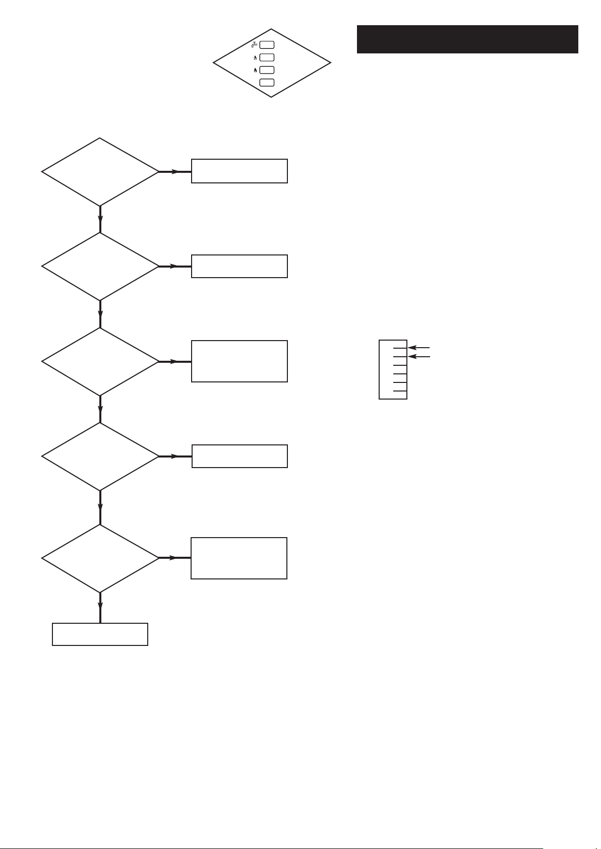
15.0 Fault Finding
54
© Baxi Heating UK Limited 2005
Replace Stat.
Replace Stat.
Wiring from PCB to
thermostats faulty.
YES
NO
YES
NO
NO
Disconnect
black stat on flow pipe.
When flow < 60° C is there
continuity across stat ?
Replace combustion
chamber door seal & trim
seal.
NO
YES
NO
YES
Reconnect stat.
Disconnect fan stat.
When fan temp < 60° C
is there continuity
across stat ?
Reconnect stat.
Disconnect the larger of
the 6-way PCB connectors.
Is there continuity
across M ?
Disconnect
thermistor
(red sensor on flow pipe).
Is resistance between
0.5kΩ & 20kΩ ?
Is
combustion chamber
door seal damaged or not in
place ?
Replace PCB.
YES
OVERHEAT LOCKOUT
Replace thermistor.
M
Off
Flash
Off
On
ON
LED
Lights
Page 55
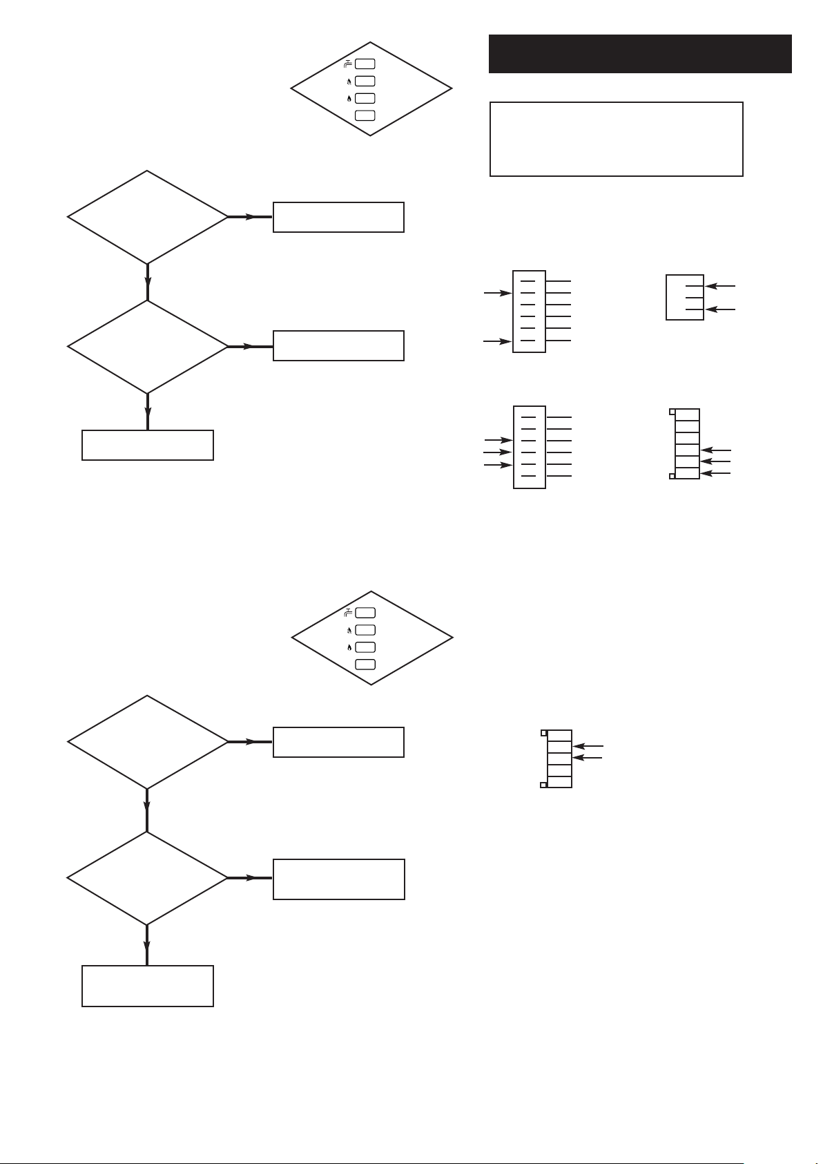
15.0 Fault Finding
55
© Baxi Heating UK Limited 2005
Rectify wiring.
NO
YES
Unplug
3-way PCB connector
& unplug fan. Is there
continuity from K to L &
from M to N ?
NO
Unplug
the smaller of the
6-way PCB connectors. Is there
continuity from O to P & from Q
to T & from
S to R ?
Replace fan.
FAN
Rectify wiring.
YES
K
M
O
S
Q
N
L
R
Viewed from
Wire Entry end
P
T
Fan
Connection
PCB
Connection
Fan
Connection
PCB
Connection
DHW FLOW SWITCH
Replace PCB.
Unplug
5-way connector
from PCB. With all DHW taps
off is there continuity
across W ?
NO
Is
DHW flow switch
blocked ?
Unblock DHW flow
switch.
NO
Replace DHW flow
switch.
YES
YES
Viewed from
Wire Entry end
W
Off
Flash
Flash
On
ON
LED
Lights
NOTE: The fan is supplied with 325 Vdc.
Fan Fault Finding should only be carried out after
the boiler has been electrically isolated.
On
On
Flash
Flash
ON
LED
Lights
Page 56
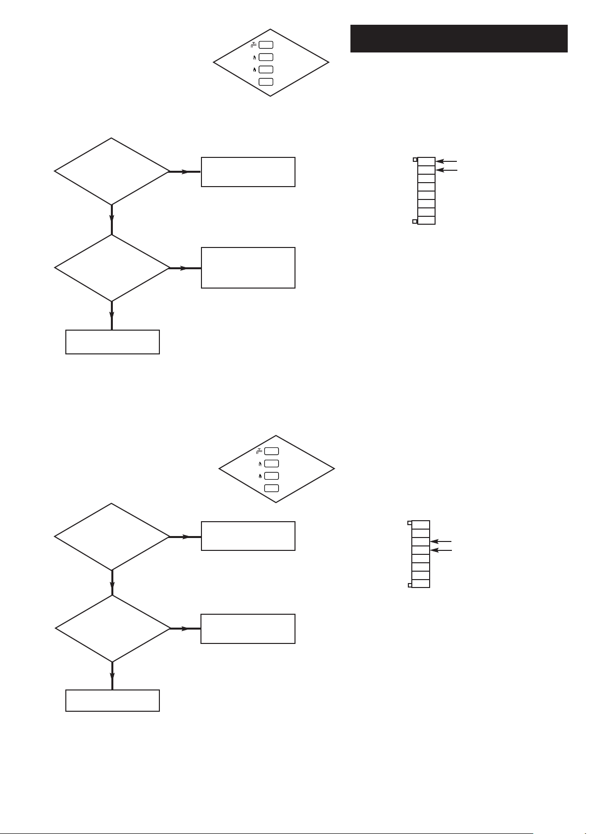
15.0 Fault Finding
56
© Baxi Heating UK Limited 2005
Replace flow thermistor.
Wiring from PCB to flow
thermistor faulty.
YES
NO
NO
YES
Replace PCB.
FLOW THERMISTOR
Unplug
flow thermistor,
Is thermistor resistance between
0.5kΩ & 20kΩ ?
Plug in
thermistor, unplug
8-way PCB connector.
Is resistance at V between
0.5kΩ & 20kΩ ?
V
Viewed from
Wire Entry end
RETURN THERMISTOR
YES
Wiring from PCB to
return thermistor faulty.
YES
Replace return thermistor.
Replace PCB.
NO
NO
U
Viewed from
Wire Entry end
Off
On
Flash
On
ON
LED
Lights
On
On
Flash
On
ON
LED
Lights
Unplug
return thermistor,
Is thermistor resistance between
0.5kΩ & 20kΩ ?
Plug in
thermistor, unplug
8-way PCB connector.
Is resistance at U between
0.5kΩ & 20kΩ ?
Page 57
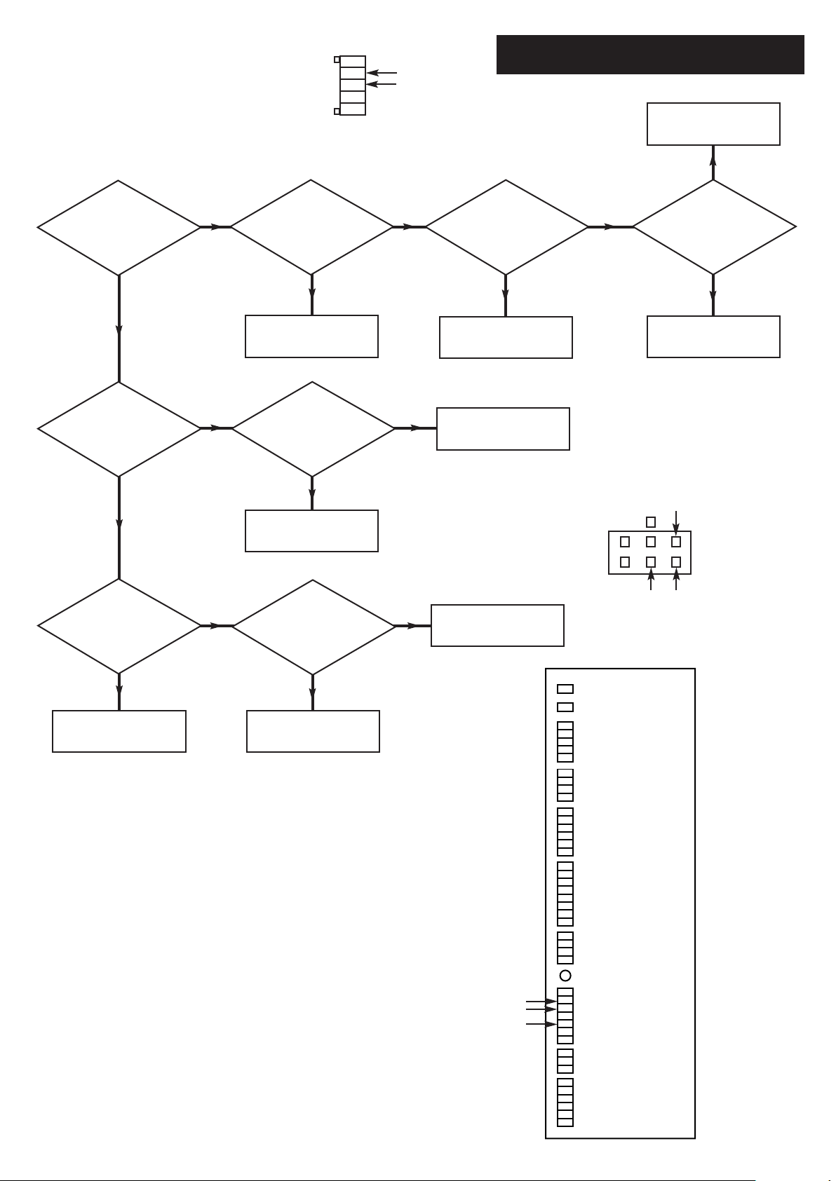
15.0 Fault Finding
57
© Baxi Heating UK Limited 2005
NO
YES
With water
flowing out of a fully
open DHW tap, does the
DHW LED light ?
Unplug
diverter valve.
With DHW LED on, is
there 240V from
Y to Z ?
NO
DHW Fault
Unplug
5-way connector
from PCB. With water flowing
out of a fully open DHW tap,
is there continuity
across X ?
Unplug
DHW F/S inline
connector. With water flowing
out of a fully open tap, is there
continuity across DHW
flow switch ?
Is DHW flow switch
blocked ?
Replace DHW Flow
Switch.
Unblock DHW Flow
Switch.
Wiring from PCB to Flow
Switch faulty.
Replace PCB.
YES
NO
Unplug
7-way PCB connector.
With DHW LED on, is
there 240V from
B to C ?
Replace PCB.
NO
Wiring from PCB to
Diverter Valve faulty.
YES
Is there 240V from
A to Z ?
YES
Unplug
7-way PCB connector.
With DHW LED on, is
there 240V from
B to D ?
Wiring from PCB to
Diverter Valve faulty.
Diverter Valve faulty. PCB faulty.
NO
NO
YES
YES
NO
YES
YES
NO
Viewed from
Wire Entry end
X
A
Z
Y
Diverter Valve Plug
(when unplugged)
B
C
D
Page 58
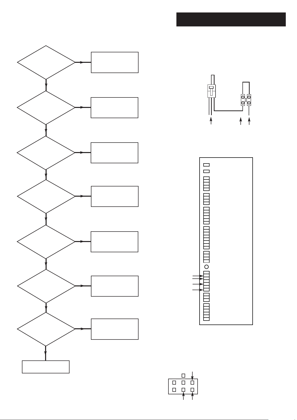
15.0 Fault Finding
58
© Baxi Heating UK Limited 2005
Wiring in 8-way terminal
block
from L to Prog 1 faulty.
Is there 240V at D ?
NO
YES
CH Fault
Check integral timer and
wiring. Check Link Plug if
no timer fitted.
Is there 240V at E ?
NO
Check external controls
wiring.
Is there 240V at F ?
NO
Check room stat & room
stat wiring OK.
Is there 240V at G ?
NO
Wiring from R/S 2 to PCB
faulty.
Is there 240V at H ?
NO
Diverter Valve faulty.
Unplug
Diverter Valve.
Ensure all DHW taps are
off so that DHW LED is off. Is
there 240V from I to J &
from K to J ?
NO
Wiring from PCB to
Diverter Valve faulty.
Is there
240V from G to N & from G
to M ?
PCB faulty.
YES
YES
YES
YES
YES
NO
I
J
K
Diverter Valve Plug
(when unplugged)
G
N
M
H
D
E F
YES
Link Plug
Page 59
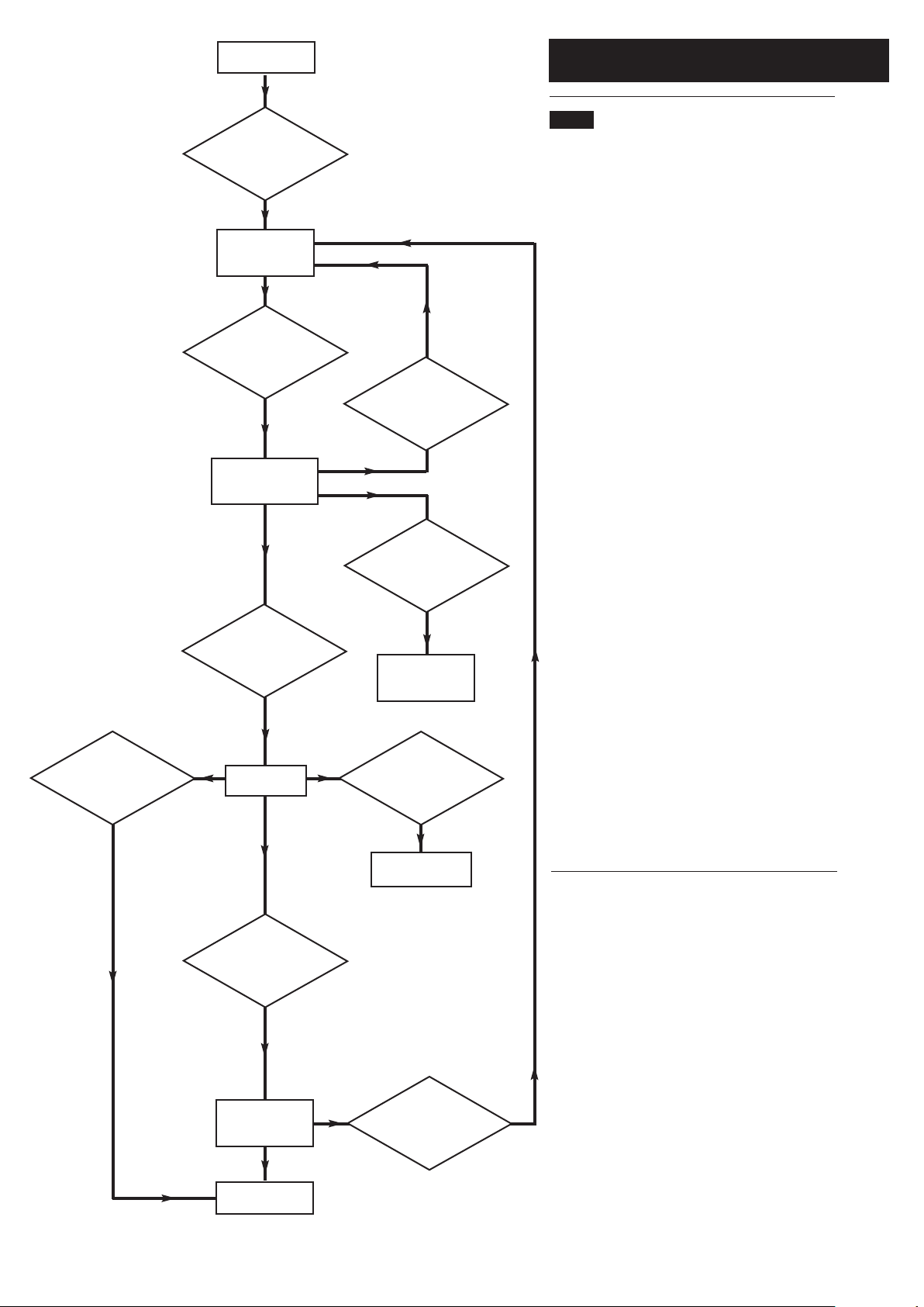
16.0 Operational Flow Chart
59
© Baxi Heating UK Limited 2005
16.1 Domestic Hot Water Mode
1. Standby: The diverter valve, pump, fan, spark
generator and gas valve are off. If a tap or shower is
switched on then Fan Pre-Purge occurs.
2. Fan Pre-Purge: The pump and fan are on while the
diverter valve, spark generator and gas valve are off.
After 5 seconds if the DHW temperature is less than
the set point then Ignition occurs.
3. Ignition: The pump, fan, spark generator and gas valve
are on while the diverter valve is off. If a flame is
detected then Burner On occurs. If a flame is not
detected within 5 seconds and less than 5 ignition
attempts have been made then Fan Pre-Purge occurs. If
a flame is not detected within 5 seconds and 5 ignition
attempts have been made then Ignition Lockout occurs.
4. Burner On: The pump, fan and gas valve are on while
the diverter valve and spark generator are off. DHW
temperature is controlled by varying the fan speed (and
thereby the gas rate) to achieve optimum operation. If
the hot water tap is turned off and the DHW
temperature has been reached and there is a Central
Heating demand then CH Burner On occurs. If the hot
water tap is turned off and the DHW temperature has
been reached and there is no CH demand then Pump
Overrun occurs. If the hot water tap is turned off and
the DHW temperature has been exceeded and there is
no CH demand then Standby occurs.
5. Pump Overrun: The pump is on while the diverter
valve, fan, spark generator and gas valve are off. If a tap
or shower is switched on then Fan Pre-Purge occurs.
After 1 minute Standby occurs.
6. Ignition Lockout: The diverter valve, pump, fan, spark
generator and gas valve are off. The boiler can only be
reset by manually using the reset button.
Standby.
Tap or shower
switched on ?
YES
5 second
Fan Pre-Purge.
Flame Detected ?
Burner On.
Ignition
Lockout.
5 second
Ignition Period.
Ignition done and
5 attempts made ?
Ignition done
and less than 5
attempts made ?
DHW temperature
less than set point ?
YES
YES
1 minute
Pump Overrun.
YES
YES
YES
Tap or
shower off & DHW
temperature >
set point ?
Standby.
Tap or shower
switched on ?
Tap or
shower off & DHW
temperature =
set point ?
CH Burner On.
Tap or
shower off & DHW
temperature =
set point ?
YES
Page 60
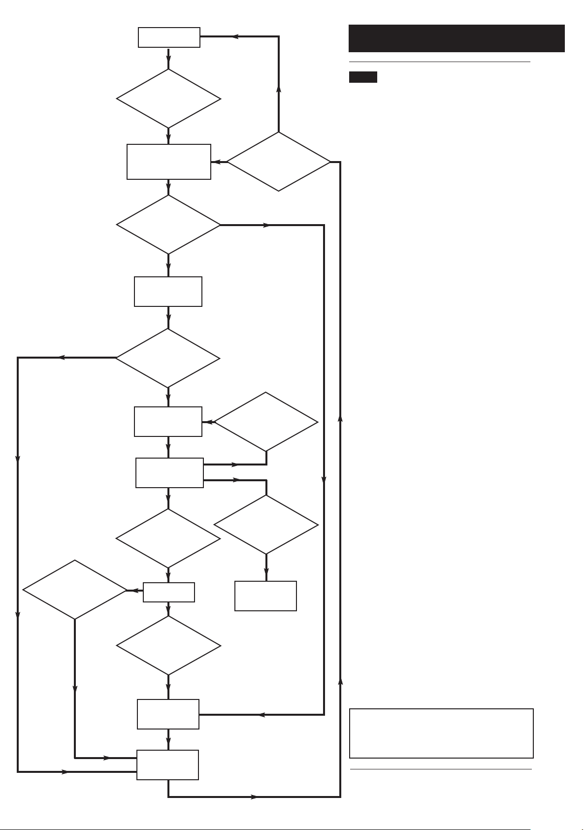
16.0 Operational Flow Chart
60
© Baxi Heating UK Limited 2005
16.2 Central Heating Mode
1. Standby: The diverter valve, pump, fan, spark
generator and gas valve are off. If the timer and room
stat are on then Diverter Valve moving to CH position
occurs.
2. Diverter Valve moving to CH position: The diverter
valve moves to the CH position while the pump, fan,
spark generator and gas valve are off. After 6 seconds if
the flow temperature is less than the set point then
Pump On occurs. After 6 seconds if the flow
temperature is greater than the set point then Pump
Overrun occurs.
3. Pump On: The diverter valve and pump are on while
the fan, spark generator and gas valve are off. After 10
seconds if the flow switch has made then Fan Pre-Purge
occurs. After 10 seconds if the flow switch has not
made then Anti-cycle occurs.
4. Fan Pre-Purge: The diverter valve, pump and fan are
on while the spark generator and gas valve are off. After
5 seconds Ignition occurs.
5. Ignition: The diverter valve, pump, fan, spark
generator and gas valve are on. If a flame is detected
then Burner On occurs. If a flame is not detected within
5 seconds and less than 5 ignition attempts have been
made then Fan Purge occurs. If a flame is not detected
within 5 seconds and 5 ignition attempts have been
made then Ignition Lockout occurs.
6. Burner On: The diverter valve, pump, fan and gas
valve are on while the spark generator are off. Flow
temperature is controlled by varying the fan speed (and
thereby the gas rate) to achieve optimum operation. If
the flow temperature is greater than the set point or
the timer is off or the room stat is off then Pump
Overrun occurs. If the TRVs all shut down then Anticycle occurs.
7. Pump Overrun: The diverter valve and pump are on
while the fan, spark generator and gas valve are off.
After 1 minute Anti-cycle occurs.
8. Anti-cycle: The diverter valve, pump, fan, spark
generator and gas valve are off. After 3 minutes Diverter
Valve moving to CH position occurs.
9. Ignition Lockout: The diverter valve, pump, fan, spark
generator and gas valve are off. The boiler can only be
reset by manually using the reset button.
NOTE: If a tap or shower is switched on during CH
Burner On then DHW Burner On occurs. If a DHW
demand occurs during any other part of CH
operation then DHW Purge occurs.
Standby.
Timer & Room Stat
on ?
NO
6 second
Diverter Valve moving to
CH position
Burner On.
Ignition
Lockout.
10 second
Pump On.
Ignition done and
5 attempts made ?
Ignition done
and less than 5
attempts made ?
Flow temperature
less than set point ?
YES
NO
1 minute
Pump Overrun.
YES
YES
YES
Timer off
or temperature >
set point or room
stat off ?
NO
Primary Flow
Switch made ?
5 second
Fan Pre-Purge.
Flame Detected ?
5 second
Ignition Period.
3 minute
Anti-cycle.
All TRVs
shut down ?
Timer off or
room stat off ?
YES
NO
YES
YES
YES
YES
Page 61

17.0 Notes
61
© Baxi Heating UK Limited 2005
Page 62
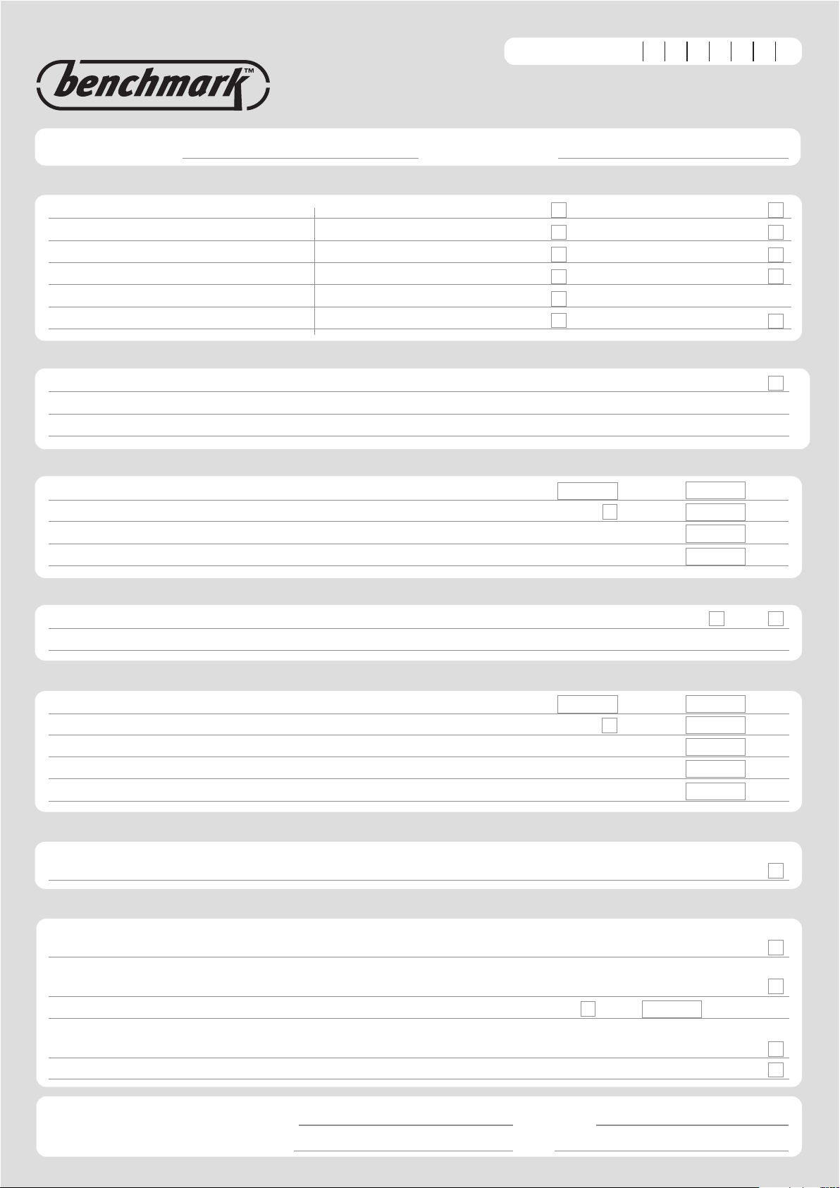
CONTROLS To comply with the Building Regulations, each section must have a tick in one or other of the boxes
TIME & TEMPERATURE CONTROL TO HEATING ROOM T/STAT & PROGRAMMER/TIMER PROGRAMMABLE ROOMSTAT
TIME & TEMPERATURE CONTROL TO HOT WATER CYLINDER T/STAT & PROGRAMMER/TIMER
COMBI BOILER
HEATING ZONE VALVES FITTED NOT REQUIRED
HOT WATER ZONE VALVES FITTED NOT REQUIRED
THERMOSTATIC RADIATOR VALVES FITTED
AUTOMATIC BYPASS TO SYSTEM FITTED NOT REQUIRED
FOR ALL BOILERS CONFIRM THE FOLLOWING
THE SYSTEM HAS BEEN FLUSHED IN ACCORDANCE WITH THE BOILER MANUFACTURER’S INSTRUCTIONS?
THE SYSTEM CLEANER USED
THE INHIBITOR USED
FOR THE CENTRAL HEATING MODE, MEASURE & RECORD
GAS RATE ft3/hr
BURNER OPERATING PRESSURE (IF APPLICABLE) mbar
CENTRAL HEATING FLOW TEMPERATURE °C
CENTRAL HEATING RETURN TEMPERATURE °C
FOR COMBINATION BOILERS ONLY
HAS A WATER SCALE REDUCER BEEN FITTED? YES NO
WHAT TYPE OF SCALE REDUCER HAS BEEN FITTED?
FOR THE DOMESTIC HOT WATER MODE, MEASURE & RECORD
GAS RATE ft3/hr
MAXIMUM BURNER OPERATING PRESSURE (IF APPLICABLE) mbar
COLD WATER INLET TEMPERATURE °C
HOT WATER OUTLET TEMPERATURE °C
WATER FLOW RATE
lts/min
FOR CONDENSING BOILERS ONLY CONFIRM THE FOLLOWING
THE CONDENSATE DRAIN HAS BEEN INSTALLED IN ACCORDANCE WITH
THE MANUFACTURER’S INSTRUCTIONS? YES
FOR ALL INSTALLATIONS CONFIRM THE FOLLOWING
THE HEATING AND HOT WATER SYSTEM COMPLIES
WITH CURRENT BUILDING REGULATIONS
THE APPLIANCE AND ASSOCIATED EQUIPMENT HAS BEEN INSTALLED AND COMMISSIONED
IN ACCORDANCE WITH THE MANUFACTURER’S INSTRUCTIONS
IF REQUIRED BY THE MANUFACTURER, HAVE YOU RECORDED A CO/CO2 RATIO READING? N/A YES CO/CO2 RATIO
THE OPERATION OF THE APPLIANCE AND SYSTEM
CONTROLS HAVE BEEN DEMONSTRATED TO THE CUSTOMER
THE MANUFACTURER’S LITERATURE HAS BEEN LEFT WITH THE CUSTOMER
m3/hr
m
3
/hr
COMMISSIONING ENG’S NAME PRINT CORGI ID No.
SIGN DATE
BOILER SERIAL No. NOTIFICATION No.
BENCHMARK No.
GAS BOILER COMMISSIONING CHECKLIST
COLLECTIVE MARK
N/A
N/A
5109929
62
© Baxi Heating UK Limited 2005
Page 63
SERVICE 1
DATE
ENGINEER NAME
COMPANY NAME
TEL No.
CORGI ID CARD SERIAL No.
COMMENTS
SIGNATURE
SERVICE 2
DATE
ENGINEER NAME
COMPANY NAME
TEL No.
CORGI ID CARD SERIAL No.
COMMENTS
SIGNATURE
SERVICE 3
DATE
ENGINEER NAME
COMPANY NAME
TEL No.
CORGI ID CARD SERIAL No.
COMMENTS
SIGNATURE
SERVICE 4
DATE
ENGINEER NAME
COMPANY NAME
TEL No.
CORGI ID CARD SERIAL No.
COMMENTS
SIGNATURE
SERVICE 5
DATE
ENGINEER NAME
COMPANY NAME
TEL No.
CORGI ID CARD SERIAL No.
COMMENTS
SIGNATURE
SERVICE 6
DATE
ENGINEER NAME
COMPANY NAME
TEL No.
CORGI ID CARD SERIAL No.
COMMENTS
SIGNATURE
SERVICE 7
DATE
ENGINEER NAME
COMPANY NAME
TEL No.
CORGI ID CARD SERIAL No.
COMMENTS
SIGNATURE
SERVICE 8
DATE
ENGINEER NAME
COMPANY NAME
TEL No.
CORGI ID CARD SERIAL No.
COMMENTS
SIGNATURE
SERVICE 9
DATE
ENGINEER NAME
COMPANY NAME
TEL No.
CORGI ID CARD SERIAL No.
COMMENTS
SIGNATURE
SERVICE 10
DATE
ENGINEER NAME
COMPANY NAME
TEL No.
CORGI ID CARD SERIAL No.
COMMENTS
SIGNATURE
SERVICE INTERVAL RECORD
It is recommended that your heating system is serviced regularly
and that you complete the appropriate Service Interval Record Below.
Service Provider. Before completing the appropriate Service Interval Record below, please ensure you have carried out the service
as described in the boiler manufacturer’s instructions. Always use the manufacturer’s specified spare part when replacing all controls
63
© Baxi Heating UK Limited 2005
Page 64

© Baxi Heating UK Limited 2005
Comp No5109929 - Iss 6 - 10/07
BAXI
A Trading Division of Baxi Heating UK, a division of Baxi Group
Brooks House, Coventry Road, Warwick. CV34 4LL
After Sales Service 08700 60 30 60 Technical Enquiries 08706 049 049
Website www.baxi.co.uk
e&oe
company
All descriptions and illustrations provided in this leaflet have been
carefully prepared but we reserve the right to make changes and
improvements in our products which may affect the accuracy of the
information contained in this leaflet. All goods are sold subject to our
standard Conditions of Sale which are available on request.
 Loading...