

Baxi Bermuda Inset 3 BS, Bermuda Inset 3 TS, Bermuda Inset 3 FS, Bermuda Inset 3 KS User, Installation And Servicing Instructions
Page 1
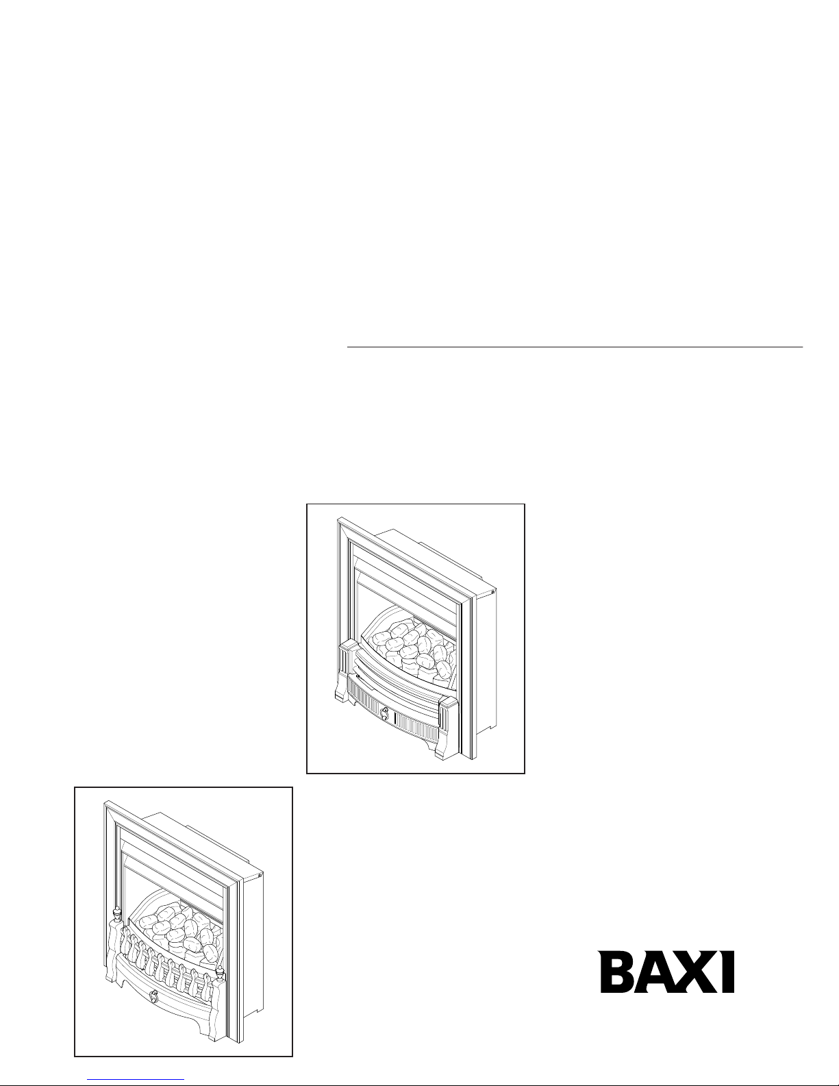
Baxi Bermuda Inset 3 Range
Fireside Gas Central Heating Units
Installation and
Servicing Instructions
Please leave these instructions with the user
TS, BS & KS
FS
Page 2

2
Baxi UK Limited is one of the leading manufacturers
of domestic heating products in the UK.
Our first priority is to give a high quality service to our
customers. Quality is built into every Baxi product -
products which fulfil the demands and needs of
customers, offering choice, efficiency and reliability.
To keep ahead of changing trends, we have made a
commitment to develop new ideas using the
latest technology - with the aim of continuing to
make the products that customers want to buy.
Everyone who works at Baxi has a commitment to
quality because we know that satisfied customers
mean continued success.
We hope you get a satisfactory service from Baxi. If
not, please let us know.
Natural Gas
Baxi Bermuda Inset 3 TS
G.C.No. 37 075 53
Baxi Bermuda Inset 3 BS
G.C.No. 37 075 52
Baxi Bermuda Inset 3 KS
G.C.No. 37 075 50
Baxi Bermuda Inset 3 FS
G.C.No. 37 075 51
For use with the following boiler:
Baxi Bermuda Inset 2 Boiler 50/4
G.C.No. 44 075 01
Baxi is a BS-EN ISO 9001
Accredited Company
Page 3
3
1.0 Introduction 4
2.0 Technical Data 5
3.0 Site Requirements 6
Fireplace Opening
Hearth Mounting
Ventilation
4.0 Installation 8
Initial Preparation
Gas Supply
Fitting the Fire
5.0 Arranging the Coals 9
Arranging the Coals
Commissioning the Fire
Arranging the Coals (cont)
6.0 Checking for Spillage 12
Checking for Spillage
The Spillage Checking Procedure
Possible Causes of Spillage
Completion
7.0 Annual Servicing 14
Annual Servicing
Preparation
Removal of Controls
Cleaning the Burner & Injectors
Cleaning the Pilot/A.S.D. Assembly
Cleaning the Combustion Box & Coals
Replacing the Fire
8.0 Changing Components 18
Changing Components
Burner and Injector
Pilot/A.S.D. Assembly
Gas Tap
Igniter Unit
Electro-Magnetic Unit
9.0 Fault Finding 21
10.0 Short Parts List 22
Section Page
Contents
Page 4
1.0 Introduction
4 1
1.1 Description
1. The Baxi Bermuda Inset 3 TS, Inset 3 BS, Inset
3 KS and Inset 3 FS are combined gas fired
central heating boiler and gas fire units, designed
for installation in a living room with a heat input of
6.52kW (22,246 Btu/h) at maximum setting.
2. The boiler and fire unit is designed to be used
on Natural Gas only.
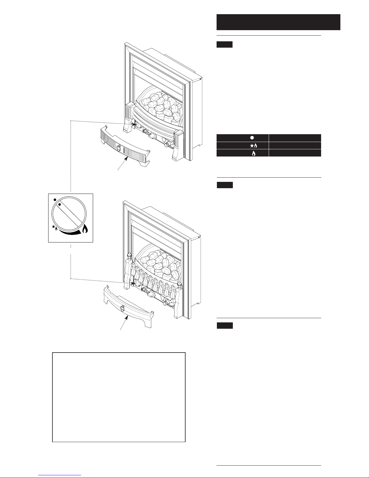
3. The fire is controlled by a knob which is
positioned behind the controls access door on the
fender assembly (Fig. 1). The knob has three
positions:
4. The control can be set anywhere between LOW
and HIGH.
1.2 Installation
1. The appliance is suitable for installation only in
G.B. and I.E. and should be installed in
accordance with the rules in force. For Ireland
install in accordance with I.S.813 “I
NSTALLATION OF
GAS APPLIANCES”. The installation must be carried
out by a CORGI Registered Installer or other
competent person and be in accordance with the
relevant requirements of G
AS SAFETY (Installation
and Use) R
EGULATIONS, the BUILDING REGULATIONS
(Scotland) (Consolidation), the LOCAL BUILDING
REGULATIONS, the CURRENT I.E.E. WIRING
REGULATIONS and the bye laws of the Local Water
Undertaking. Where no specific instructions are
given, reference should be made to the relevant
BRITISH STANDARD CODES OF PRACTICE.
2. These Instructions must be read in
conjunction with those for the Boiler Section
before installing or using this appliance.
1.3 Important Information
This product contains Refractory Ceramic Fibres
(R.C.F.) which are man-made vitreous silicate fibres.
Excessive exposure to these materials may cause
temporary irritation to eyes, skin and respiratory tract.
Care must be taken when handling these articles to
ensure the release of dust or fibres is kept to a
minimum. To ensure that the release of fibres from
these articles is kept to a minimum, during installation
and servicing it is recommended that a H.E.P.A.
filtered vacuum is used to remove any dust, soot or
other debris accumulated in and around the
appliance. This should be performed before and after
working on the installation. It is recommended that
any replaced item(s) are not broken up but sealed
within heavy duty polythene bags and clearly labelled
“R.C.F. waste”. This is not classified as “hazardous
waste” and may be disposed of at a tipping site
licensed for the disposal of industrial waste.
Protective clothing is not required when handling
these articles but it is recommended that gloves are
worn and the normal hygiene rules of not smoking,
eating or drinking in the work area are followed and
always wash hands before eating or drinking.
Position
Position
Position
OFF
IGNITION / PILOT / LOW
HIGH OUTPUT
Notice
Discolouration of wall surfaces
Most heating appliances generate warm air convection currents and
transfer heat to any wall surface against which they are situated.
Some soft furnishings (such as blown vinyl wallpapers) may not be
suitable for use where they are subject to temperatures above normal
room levels and the manufacturer's advice should be sought before
using this type of wall covering adjacent to any heating appliance.
The likelihood of wall staining from convected air currents will be
increased in environments where high levels of cigarette smoke or
other contaminants exist.
BAXI Bermuda Inset 3
OFF
Controls Access Door
Controls Access Door
Control Knob
Bermuda Inset 3 TS
Bermuda Inset 3 BS
Bermuda Inset 3 KS
Bermuda Inset 3 FS
Fig. 1
Page 5

2.0 Technical Data
1 5
Bermuda Inset 3 TS
Bermuda Inset 3 BS
Bermuda Inset 3 KS
Bermuda Inset 3 FS
The fire is set for Gas Type G20 at 20mbar.
Heat Input High Low
kW 6.52 4.1
Btu/h 22,246 13,989
Setting Pressure Cold
mbar 9.0
in wg 3.6
Thermocouple 6.5 - 10.0 mv
Output
Gas Connection The gas supply is
provided from the service
cock on the boiler unit
Controls Rotary gas tap with flame
failure device and
atmospheric sensing
device
Gas Rate
(after 10 mins) 0.60 m
3
/h (21.0 ft3/h)
Installation
Lifting Weight 8.5 kg (18.7 lbs)
Outercase Height 610mm
Dimensions Width 593mm
Depth 103mm
(from the wall)
STANDARD
B.S. 6891
B.S. 5546
B.S. 5449
B.S. 6798
B.S. 5440: Pt 1
B.S. 5440: Pt 2
B.S. 5871: Pt 1
B.S. 6500
SCOPE
Gas Installation.
Installation of hot water supplies for
domestic purposes.
Forced circulation hot water systems.
Installation of gas fired hot water
boilers.
Flues
Air Supply.
Installation of fire/back boilers, gas
appliances.
Cables.
B.S. Codes of Practice
NOTE: All illustrations show the Inset 3 TS. The
procedure for Installation, Commissioning, Servicing
etc. is the same for all Bermuda Inset 3 models
.
Page 6
3.0 Site Requirements
6 1
3.1 Fireplace Opening
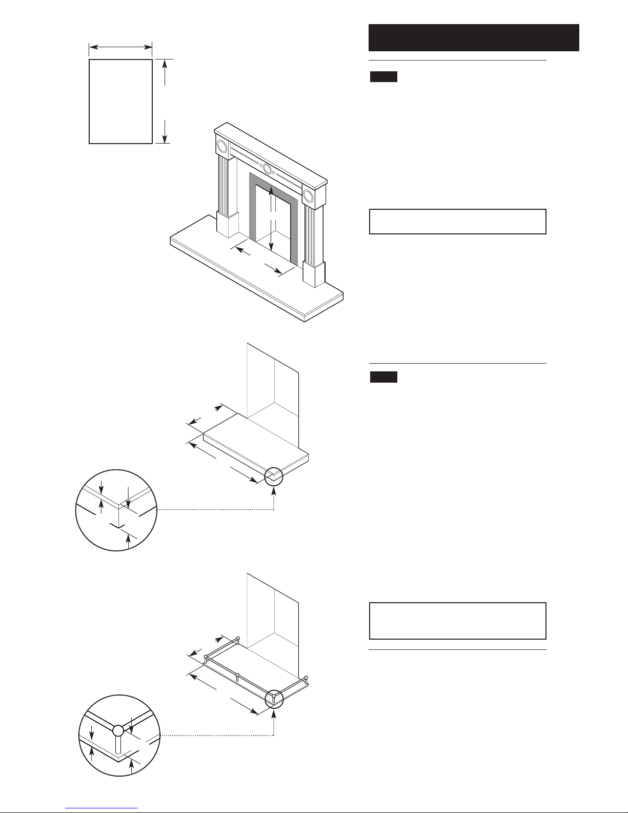
1. The principal site requirements are determined
by the boiler unit, but the following details are
essential for the correct installation of the fire unit:
Fireplace Opening (Fig. 2):
Height: 560mm (22in) min
590mm (23
15
/64in) max
Width: 460mm (18in) min
560mm (22in) max
NOTE: The wall or surround behind the fire
must be non-combustible.
Non-Combustible area (Fig. 3):
Height 625mm (24
19
/32in)
Width 625mm (24
19
/32in)
2. Any gaps between the wall and the surround
must be sealed. A shelf, not projecting more than
178mm (7in), may be fitted at least 126mm (5in)
above fire or 180mm (7
1
/8in) for 229mm (9in)
deep shelf.
3.2 Hearth Mounting
1. The fire unit is intended to be hearth mounted.
The hearth must be of a non-combustible
material at least 13mm (
1
/2in) thick and measuring
at least 300mm (12in) deep by 600mm (23
5
/8in)
wide and fitted centrally about the fireplace
opening. The top surface of the hearth should be
a minimum of 50mm (2in) above floor level and
must be level with the base of the builders
opening (Fig. 4).
2.
On no account should the fire unit be fitted
directly onto a combustible floor or carpet.
3. Alternatively, a fender rail or upstanding edge
of 50mm (2in) height can be fitted to the
periphery of the 13mm (
1
/2in) non-combustible
hearth (Fig. 5).
NOTE: If the firefront must be wall mounted, it
is still necessary to fit a hearth of the
dimensions shown.
460mm Min
560mm Max
Fireplace
Opening
560mm
Min
590mm
Max
Fireplace Opening
Surround and
Non-Combustible Area
Minimum Hearth
Dimensions
300mm
600mm
50mm
13mm
625mm
625mm
300mm
600mm
50mm
13mm
Fig. 2
Fig. 3
Fig. 4
Fig. 5
Page 7

3.0 Site Requirements
1 7
3.3 Ventilation
1. Ventilation air supply to BS 5440 Pt 2 is
required. The permanent ventilation area size
requirements are as shown:
80.1cm
2
12.42in
2
2. The permanent vent may be directly into the
room containing the appliance. The vent may
also be sited in another (not a bedroom, toilet,
bathroom or kitchen) room provided an
interconnecting vent is used.
3. The vent must not be installed inside the
builders opening. The vent should be sited
following good practise for a habitable room.
4. We recommend the use of the Stadium
BM720 “Black Hole” ventilator which is available
from your local merchant.
Page 8
4.0 Installation
8 1
4.1 Initial Preparation
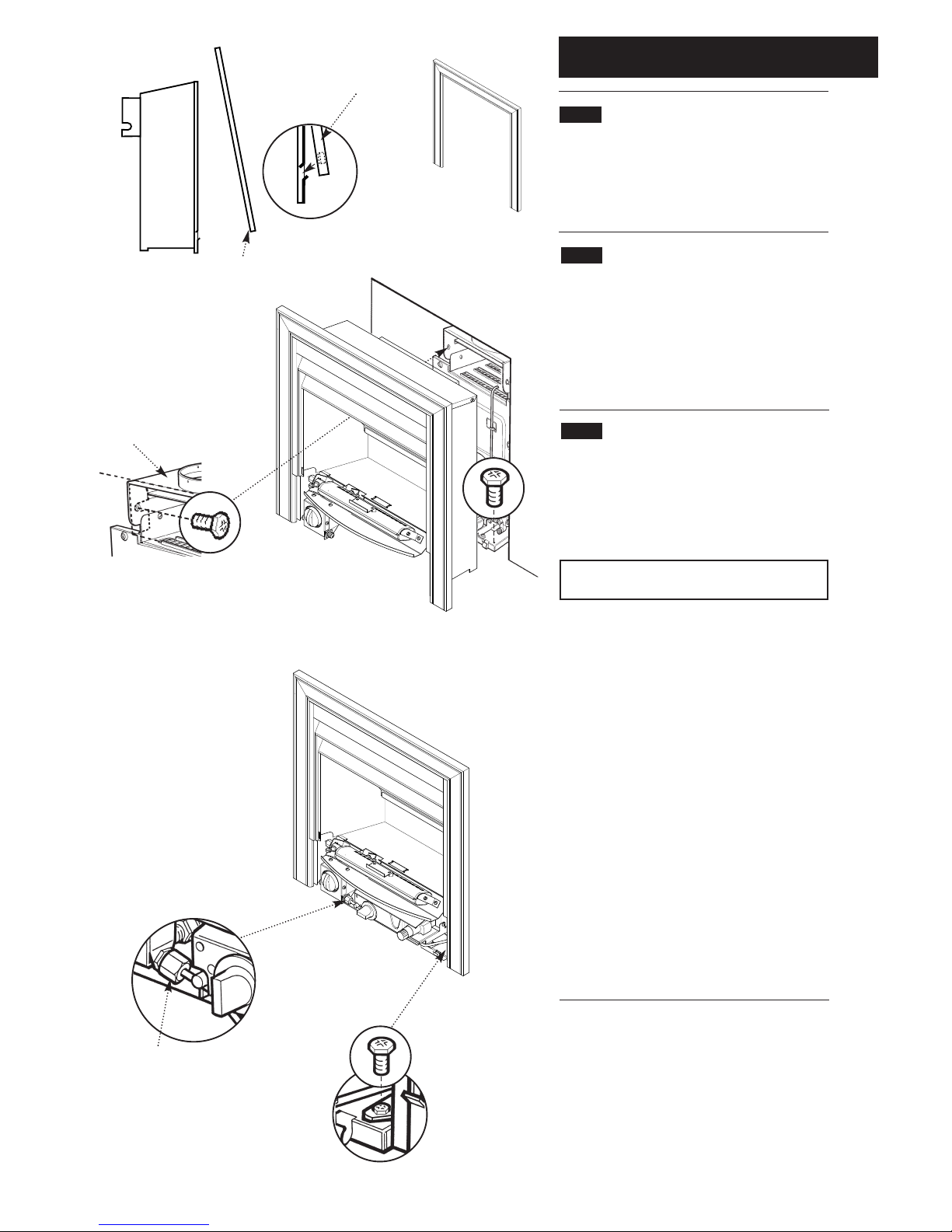
1. Unpack the fire unit from the box. The fire
surround, coal bed and fender assembly are
packed in individual boxes within the main carton
and should be left in these boxes until required.
4.2 Gas Supply
1. The gas installation should be in accordance
with BS6891. The gas supply to the fire is
provided from the service cock on the boiler
using the supply pipe provided in the fire kit. The
pipe is the correct length and will not need
shortening.
4.3 Fitting the Fire
1. Remove the two thread forming screws from
the front corners of the boiler base tray (Fig. 8).
2. Remove the fire surround from its packaging
(Fig. 6).
NOTE: The surround is easily distorted and
should be handled carefully.
3. Position the fire surround around the fire
combustion box and lower it into position,
ensuring that the top lugs locate onto the top of
the fire combustion box and the bottom lugs
locate into the slots in the sides of the
combustion box (Fig. 7).
4. Position the fire in the fireplace opening and
ensuring that the flue spigot locates into the
downdraught diverter on the boiler, push the fire
back into the opening. Look through the fire to
align the two slots in the flue spigot with the holes
in the boiler hood (Fig. 9).
5. Fit the two screws that locate the fire
combustion box to the boiler base tray (Fig. 10).
6. Fit and tighten the two screws inside the fire
flue spigot (Fig. 9).
7. Fit the fire gas supply pipe (Fig.11).
Fire Gas Supply Pipe
Flue
Spigot
Bottom
Lug
Boiler Hood
Fire Surround
Fire Surround
Fig. 7
Fig. 6
Fig. 8
Fig. 9
Fig. 11
Fig. 10
Fire Surround
Page 9
5.0 Commissioning the Fire
9
5.1 Commissioning the Fire
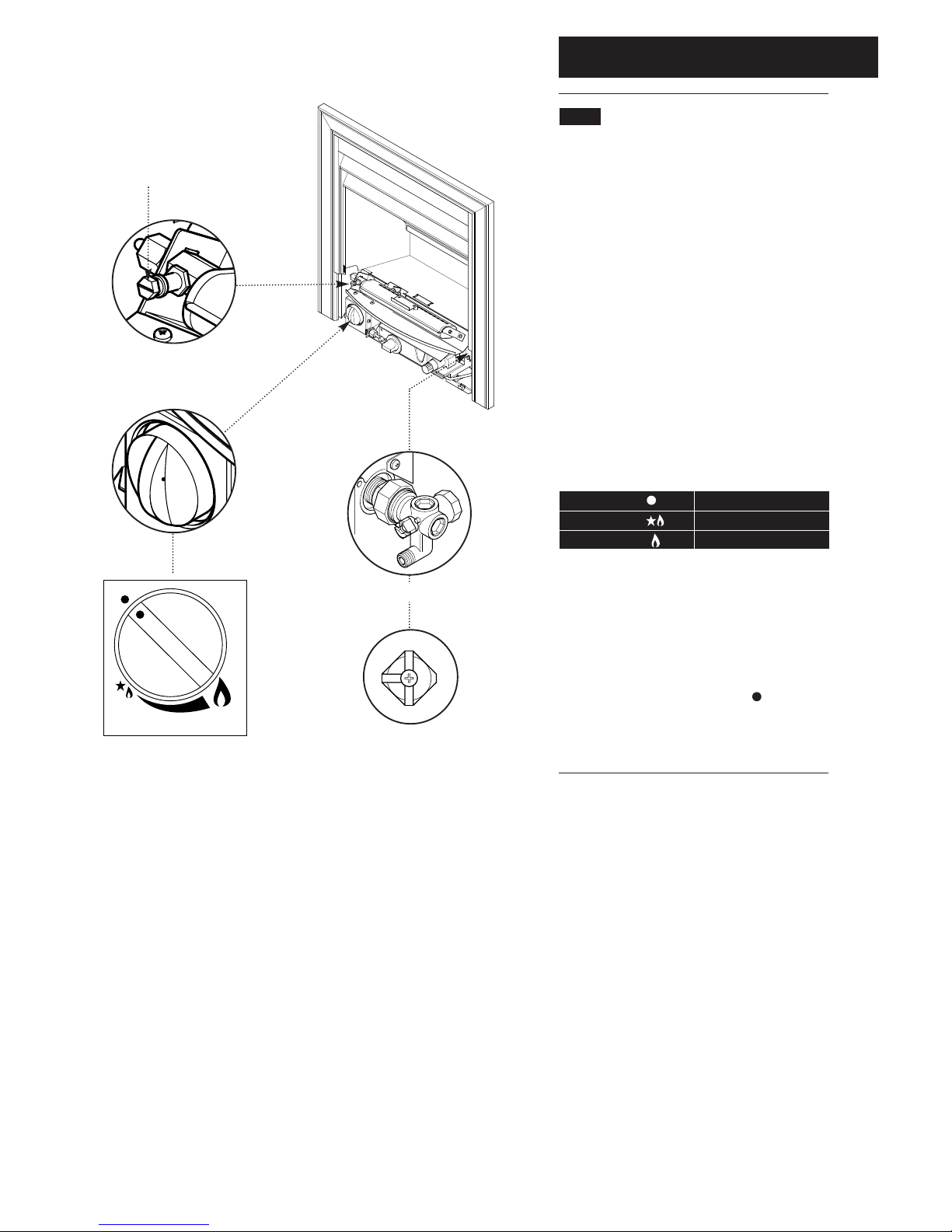
1. Turn on the main gas supply.
2. Turn the gas service cock to the fire and boiler
on position as shown, then purge any air from the
flre supply pipe (Fig. 12).
3. Check for gas soundness from the gas service
cock to the fire inlet connection. (BS 6891).
4. Release the pressure test point sealing screw
from the injector adaptor and connect a pressure
gauge (Fig. 13).
5. Push in the control knob and turn anticlockwise to the ignition position and hold in for
10 seconds. If the fire fails to remain alight, or
goes out at any time, wait 2 minutes and repeat
the procedure. Turn the control knob to the High
position (Fig. 14).
6. Check the fire gas pressure.
The pressure should be 9.0 mbar (3.6 in wg). If
the pressure is not correct, check that all gas
cocks are fully open and that the meter pressure
is correct. No adjustment to the setting pressure
is possible.
7. Turn the control knob to the off ( ) position.
Disconnect the pressure gauge and replace the
pressure test point sealing screw, ensuring a gas
tight seal (Figs. 13 & 14).
BAXI Bermuda Inset 3
OFF
Pressure Test Point
Sealing Screw
Gas Service Cock
Fire and Boiler
ON Position
Control Knob and Bezel
Fig. 13
Fig. 14
Fig. 12
Position
Position
Position
OFF
IGNITION / PILOT / LOW
HIGH OUTPUT
Page 10
6.0 Arranging the Coals
10
Fig. 15
Fig. 16
6.1 Arranging the Coals
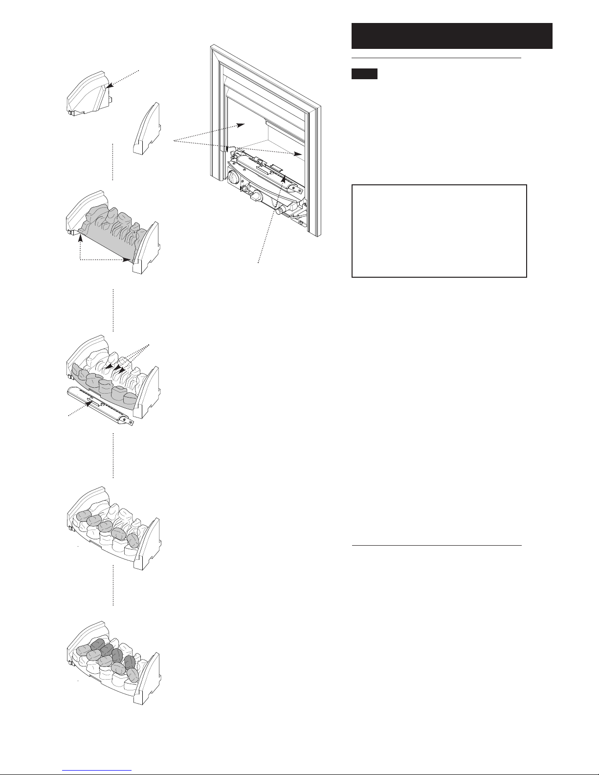
It is important that all the coals are used and
arranged as shown in order to achieve the
desired flame picture.
1. Remove the loose coals, side cheeks, rear and
front coals from their protective packaging and
place them on a newspaper or similar to prevent
soiling furnishings.
CAUTION: The coals are extremely fragile and
must be handled accordingly. Gloves should be
worn and any inhalation of the dust should be
avoided. Keep the coals away from children at
all times. Never use coals other than those
originally supplied or Genuine Baxi Spare
Parts. Never put additional coals on the fire.
Please read section 1.3 Important Information.
2. Place the right / left hand side cheeks against
the combustion box side walls (Fig. 15).
3. Locate the rear coal behind the combustion box
base front lip and angle it back against the side
cheek location stops Figs. 15 & 16).
4. Locate the front coal onto the rear coal side
support ledges and behind the lip of the burner
bracket (Figs. 16 & 17).
5. Place 5 of the loose coals into the location
recesses of the front coal, (flat face downward).
The 3 centre coals should rest against the
corresponding rear coal spacer lugs. Orientation
of the coals should be as shown in order to
achieve the desired flame picture (Fig. 18).
6. Place the remaining 4 loose coals between the
front loose coals and the rear coal, (flat face
downward). Orientation of the coals should be as
shown in order to achieve the desired flame
picture (Fig. 19).
Fig. 17
Fig. 18
Fig. 19
Combustion Box Base Front Lip
Side Cheek
Location Stop
Rear Coal Side
Support Ledges
Burner
Bracket Lip
Rear Coal Spacer Lugs
Page 11
6.0 Arranging the Coals
11
6.1 Arranging the Coals (cont)
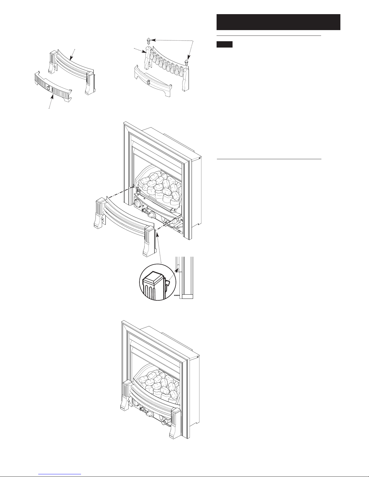
7. At this point it is necessary to fit the fender
assembly.
8. Remove the fender from its packing (Fig. 20)
(on FS models screw the finials to the fender
assembly).
9. Remove the controls access door from the
fender assembly (Fig. 20).
10. Hook the fender into the sides of the
combustion box (Fig. 21).
11. The appliance must now be checked for
spillage.
Fig. 21
FS model
Fender Assembly
Finial
Controls Access Door
Fig. 20
Controls Access
Door
Fender
Fender
Page 12
7.0 Checking for Spillage
12
7.1 Checking for Spillage
CAUTION - Whilst checking for spillage care
must be taken to avoid touching hot panels.
1. Before checking for spillage the worst likely
operating environment for the appliance must be
created. To do this, close all doors and windows
in the room and operate any ceiling or extractor
fans that may be present, on the wall or within
other appliances. If any ceiling or extractor fans
are present in an adjoining room then these
should be operated and the connecting door left
open.
2. There are two stages of appliance operation for
which spillage must be checked by following "The
Spillage Checking Procedure" shown below (7.2).
3. STAGE 1 - Commencing with the appliance
Cold, operate the fire on maximum for five
minutes and check for spillage. If spillage is
evident then the fire is operated for a further 10
minutes and re-checked. If spillage is still evident
then the cause should be ascertained and
rectified before continuing with commissioning.
4. STAGE 2 - Following a satisfactory result at
stage 1, the fire is left on and the boiler is
operated (from Cold) for 5 minutes before
checking for spillage again. If spillage is evident
then the cause should be ascertained and
rectified before continuing with commissioning.
5. If the appliance cannot be commissioned then
it should be isolated until the problem is resolved.
7.2 The Spillage Checking Procedure
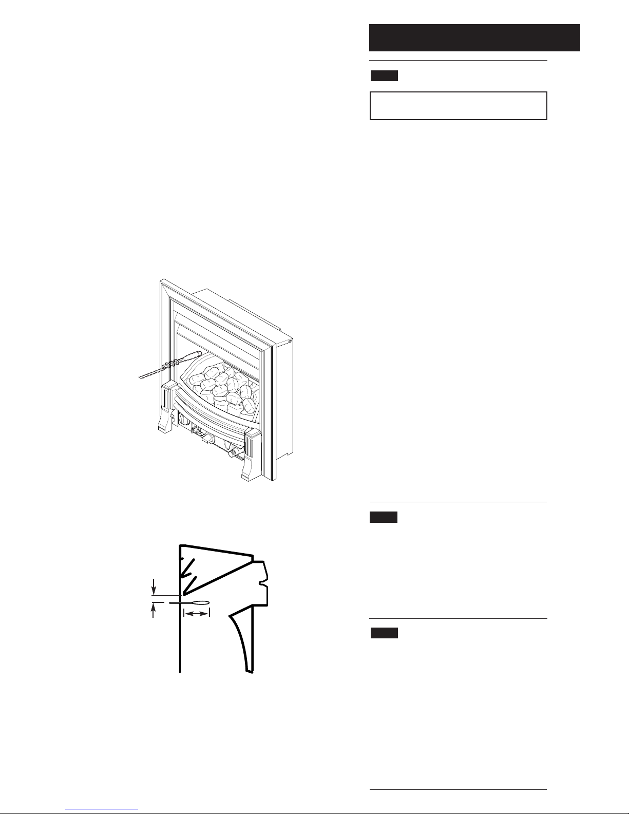
1. A lighted smoke match should be held in a
suitable holder 50mm below the lower louvre of
the fire and 50mm from either side of the
combustion box inner side panel. The majority of
smoke should be drawn into the fire (Figs. 22 &
23).
7.3 Possible Causes of Spillage
1. The smoke match may have been positioned
incorrectly, resulting in the smoke being picked up
by hot convected air currents.
2. The builders opening or flue installation may be
unsound.
3. Inadequate ventilation.
4. Down draughts may be present.
5. Flue blockages.
Insert the smoke match 50mm from
either side of the combustion box
inner side panel
60mm
50mm
Fig. 22
Fig. 23
Page 13
7.0 Checking for Spillage
13
7.4 Completion
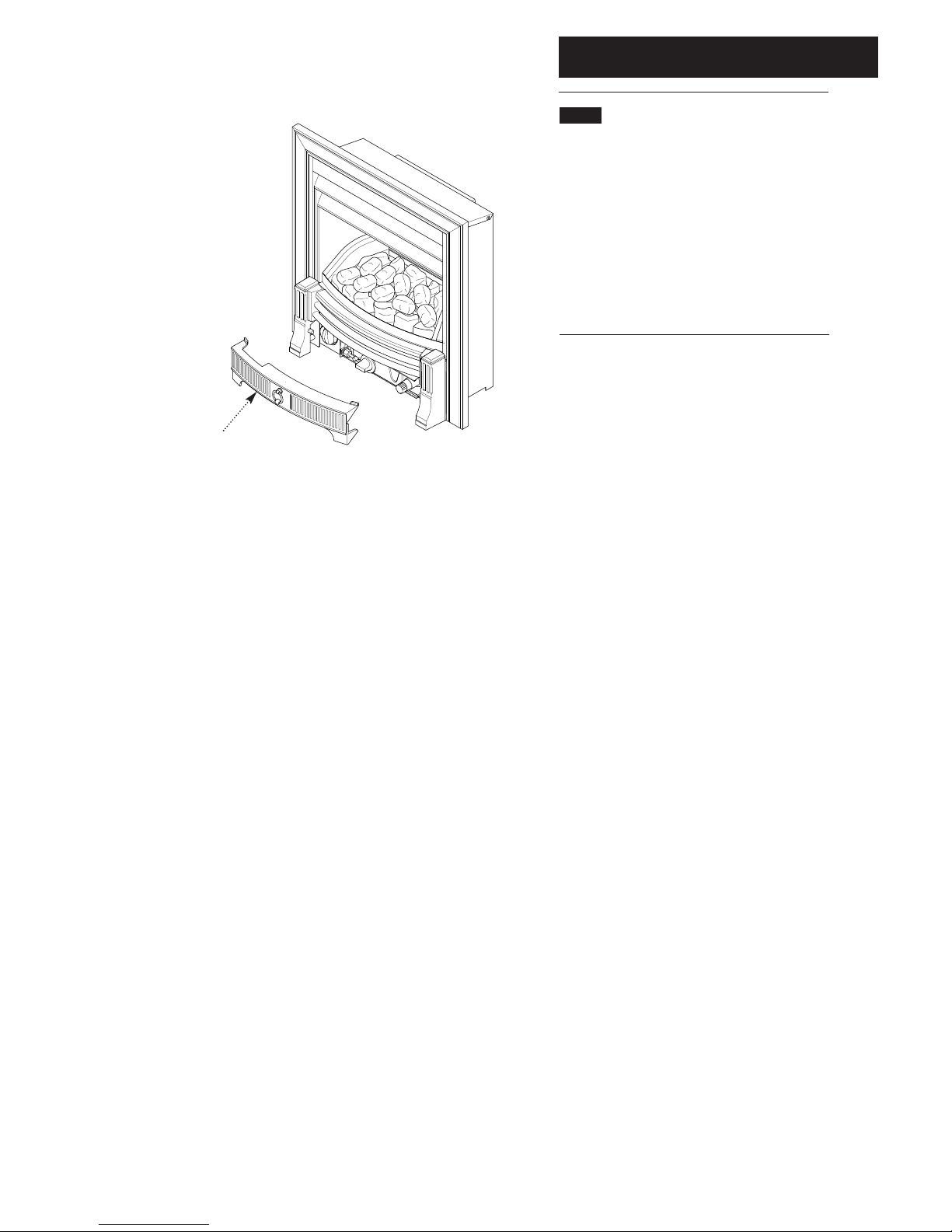
1. Replace the controls access door (Fig. 24).
2. These instructions and the users instructions
should be handed to the customer. At the same
time the customer should be shown how to
operate the fire and boiler safely and efficiently.
3. The need for annual servicing should be
emphasised and the returning of the guarantee
card advised.
Fig. 24
Controls Access Door
Page 14
8.0 Annual Servicing
14
8.1 Annual Servicing
IMPORTANT: It is possible that some soot
may be deposited on the coals after use. This
is acceptable providing it is not allowed to
accumulate.
CAUTION: The coals are extremely fragile
and must be handled accordingly. Gloves
should be worn and any inhalation of the dust
should be avoided. Keep the coals away from
children at all times. Never use coals other
than those originally supplied or Genuine Baxi
Spare Parts. Never put additional coals on the
fire. Please read section 1.3 Important
Information.
1. For reasons of safety and economy it is
important to service the flre and boiler annually.
8.2 Preparation
WARNING: Isolate the gas and electricity
supplies to the boiler and fire unit before
servicing.
1. In order to service the boiler unit, the fire must
be disconnected and removed. Remove the fire
as follows-
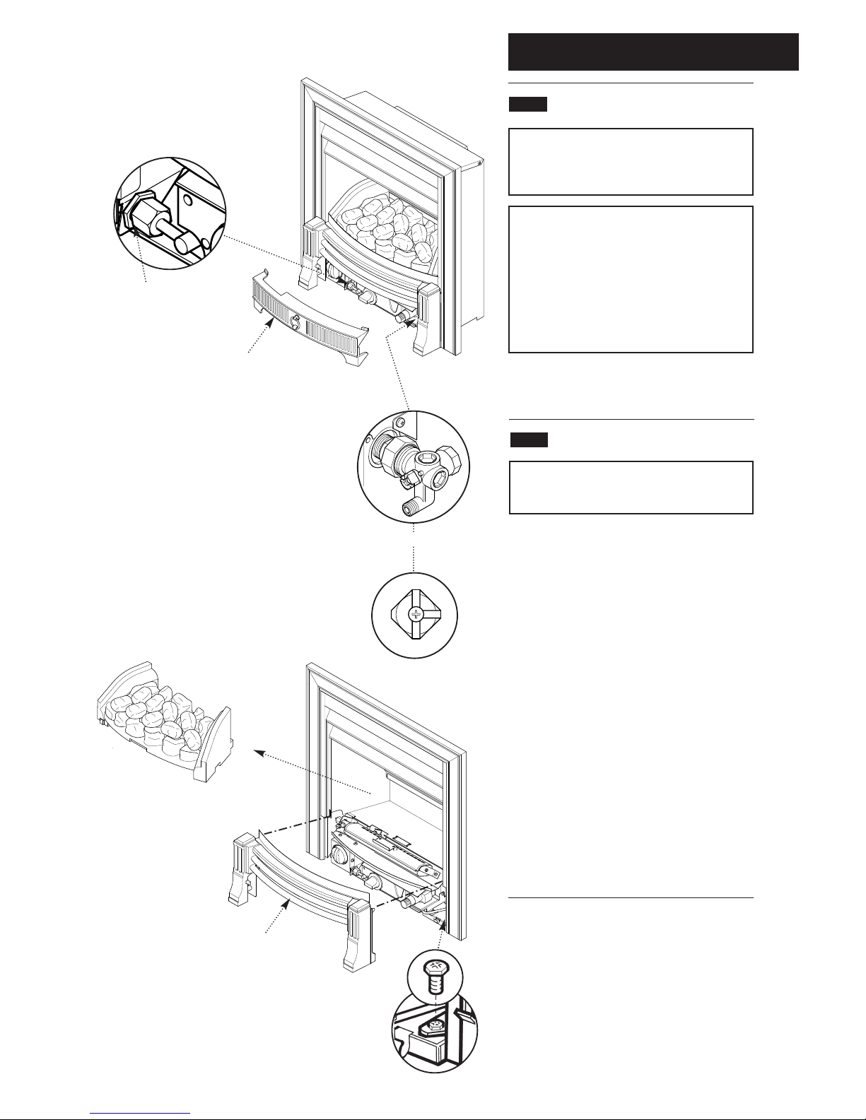
2. Lift the controls access door away from the
fender assembly (Fig. 25).
3. Turn off the gas supply at the service cock
(Fig. 27).
4. Carefully remove all the loose coals, side
cheeks, rear and front coals (Fig. 28).
5. Lift the fender assembly to disengage it from
the hooks and remove it (Fig. 29).
6. Disconnect the gas supply to the fire at the
gas tap elbow connection (Fig. 26).
7. Remove the two screws retaining the sides of
the fire combustion box to the fire base tray
(Fig. 30).
Gas Tap Elbow
Controls Access Door
Gas Service Cock
Fender Assembly
Fig. 26
Fig. 25
Fig. 27
Fig. 28
Fig. 29
Fig. 30
Page 15
8.0 Annual Servicing
15
8.2 Preparation (Cont)
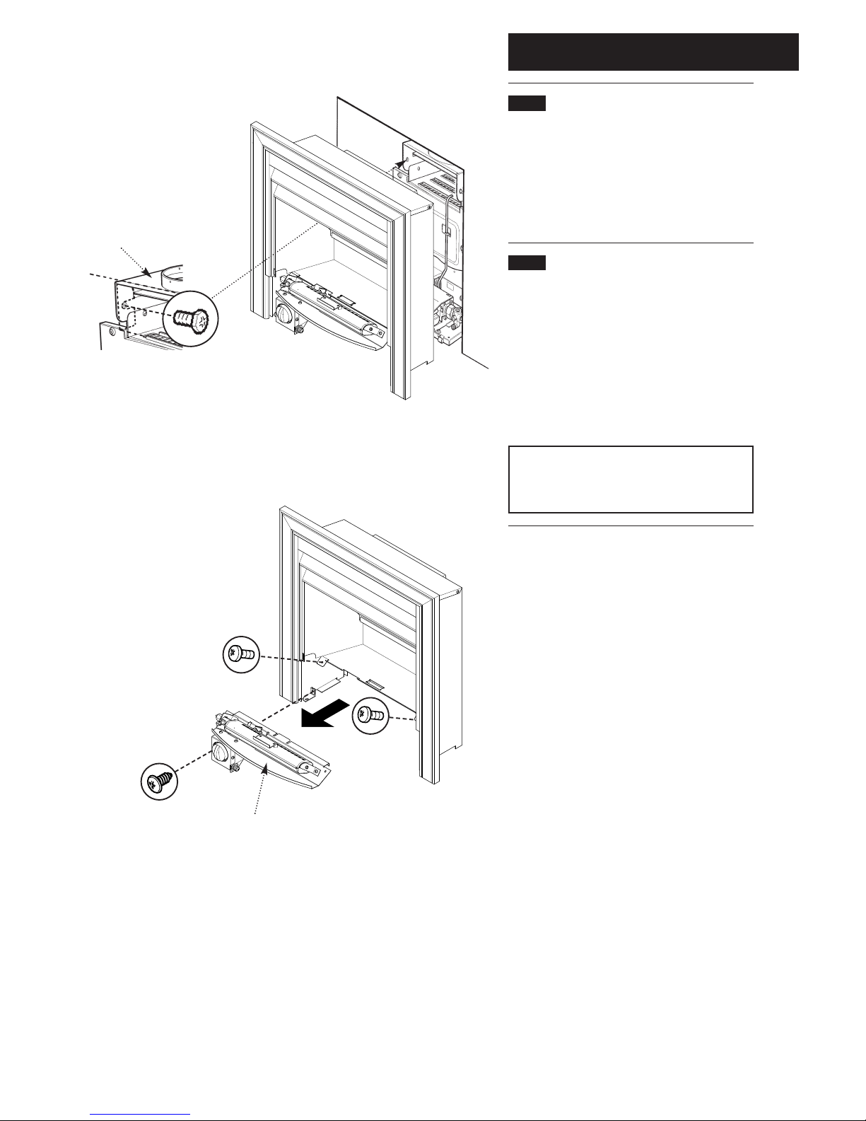
8. Remove the two screws inside the flue spigot
(Fig. 31).
9. Slide the fire combustion box forward to
disengage it from the flue spigot and lift away
(Fig. 32).
8.3 Removal of Controls (Fig. 33)
1. Undo the screw to the lower left hand side of
the fire that secures the gas tap bracket to the
combustion box.
2. Undo the two screws retaining the controls to
the combustion box.
3. Withdraw the complete controls assembly
from the fire.
NOTE: On refitting the controls assembly,
ensure that the tongue on the controls
mounting plate engages in the corresponding
slot in the combustion box lower panel.
Flue
Spigot
Boiler Hood
Controls Assembly
Fig. 31
Fig. 32
Fig. 33
Page 16
8.0 Annual Servicing
16
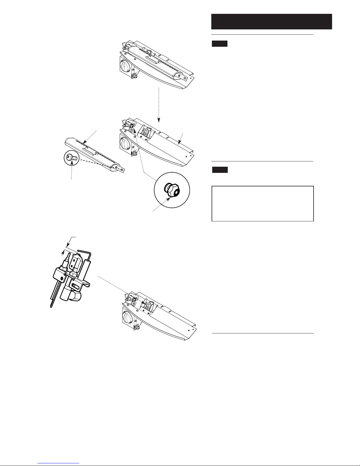
8.4 Cleaning the Burner & Injectors
1. Undo the screw holding the burner to the
controls mounting plate, and disengage the
burner inlet from the injector (Fig. 34).
2. Using a soft brush, remove any dirt from the
burner and ensure that the ports are free from
obstruction (Fig. 34).
3. Using a spanner on both the adaptor barrel
and fire injector, remove the injector from the
barrel (Fig. 35).
4. Examine and clean the injector. Do not use
any hard tools such as pins or wire. Refit the
injector (Fig. 35).
8.5 Cleaning the Pilot/A.S.D. Assembly
(Fig. 36)
NOTE: No attempt should be made to clean
the device using any hard tools, including pins
or wire.
WARNING: The pilot/A.S.D. assembly must
not be adjusted in any way.
1. The A.S.D. must not be altered so that it will
not operate or be bypassed in any way.
2. Ensure that the pilot burner aeration hole is
free from lint, debris etc.
3. If necessary clean the electrode and target,
and check that the spark gap is 2.5 - 4.0mm.
4. The thermocouple cannot be changed as an
individual component. The complete assembly
must be replaced in the event of one or other
component failure(s).
5. Only use a Genuine Baxi Spare Part.
Retaining
Screw
Injector
Burner
Controls Mounting
Plate
Complete Controls
Assembly
Pilot/A.S.D.
Assembly
2.5 - 4mm
Fig. 34
Fig. 35
Fig. 36
Page 17
8.0 Annual Servicing
17
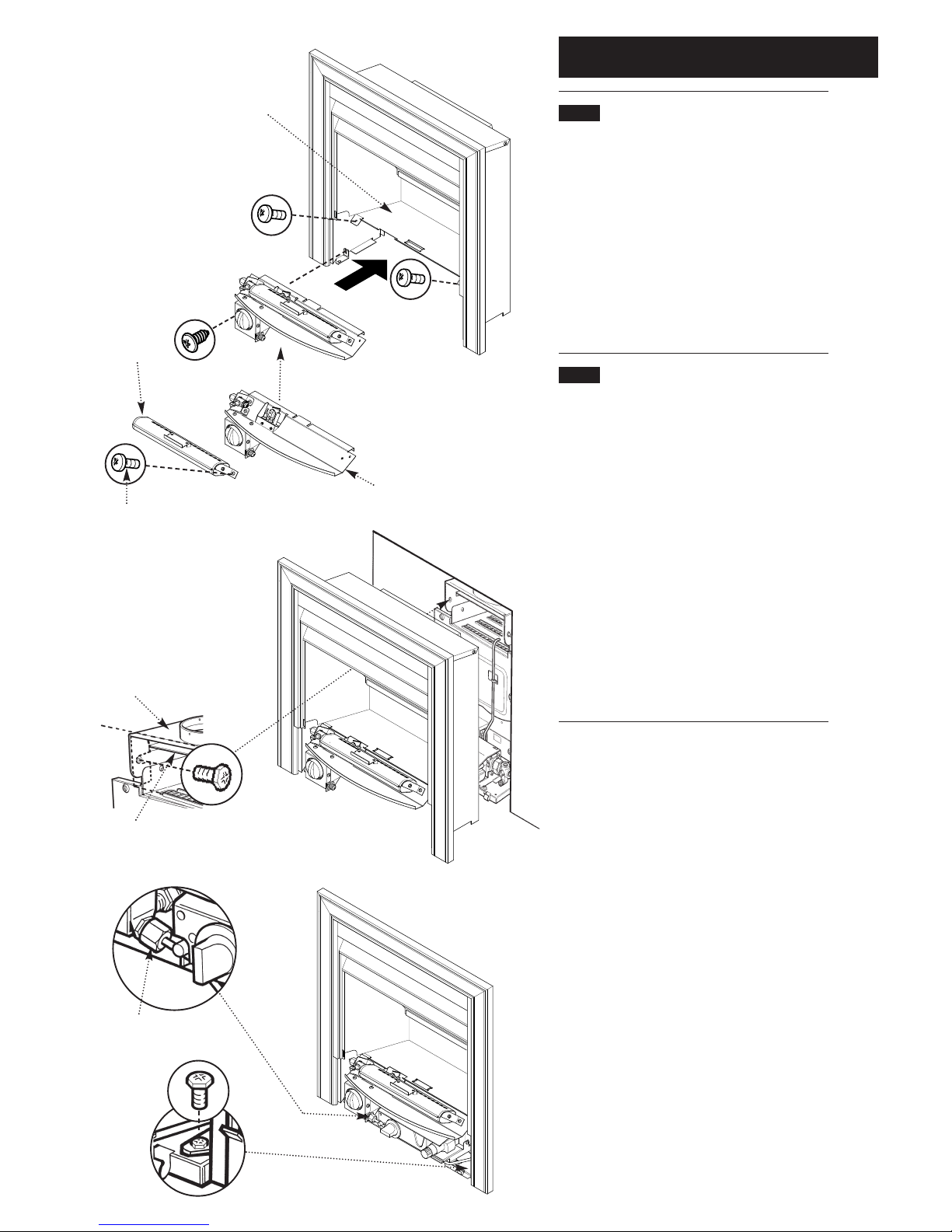
8.6 Cleaning the Combustion Box &
Coals
1. Remove any deposits from the firebed base
panel (Fig. 37).
2. If necessary the coals can be cleaned with a
very soft brush, and can be retouched using the
black stain supplied with the fire.
3. Refit the burner to the controls mounting plate
and replace the controls assembly in the
combustion box (Fig. 38).
8.7 Replacing the Fire
1. Once the boiler has been serviced, the fire can
be replaced. Refer to the boiler installation and
servicing instructions.
2. Slide the fire combustion box into position
ensuring that the flue spigot fits into the boiler
downdraught divertor. Fit and tighten the two
screws inside the flue spigot (Fig. 39) and
replace the two screws into the boiler base tray
(Fig. 41).
3. Reconnect the gas supply and test for
soundness (Fig. 40).
4. Replace all the loose coals, side cheeks, rear
and front coals as described in “Arranging the
Coals”. Refit the fender assembly.
Retaining
Screw
Burner
Controls Assembly
Controls Mounting Plate
Flue
Spigot
Boiler Hood
Fire Gas Supply Pipe
Firebed Base Panel
Boiler Downdraught
Divertor
Fig. 37
Fig. 38
Fig. 39
Fig. 40
Fig. 41
Page 18
9.0 Changing Components
18
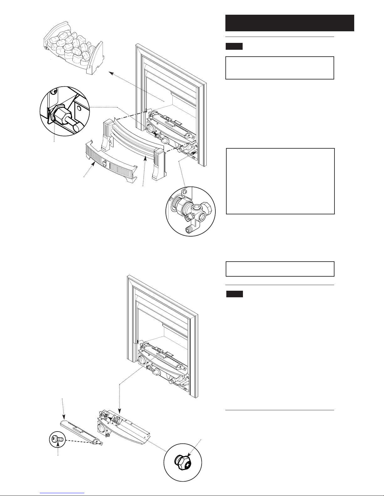
9.1 Changing Components
WARNING: Isolate the gas and electricity
supplies to the boiler and fire unit before
changing any components.
1. Lift the controls access door away from the
fender assembly (Fig. 42).
2. Turn off the gas supply at the service cock
(Fig. 45).
3. Carefully remove all the loose coals, side
cheeks, rear and front coals (Fig. 43).
CAUTION: The coals are extremely fragile
and must be handled accordingly. Gloves
should be worn and any inhalation of the dust
should be avoided. Keep the coals away from
children at all times. Never use coals other
than those originally supplied or Genuine Baxi
Spare Parts. Never put additional coals on the
fire. Please read section 1.3 Important
Information.
4. Lift the fender assembly to disengage the
hooks and remove it (Fig. 42).
6. Disconnect the gas supply to the fire at the gas
tap elbow connection (Fig. 44).
NOTE: After changing any components carry
out checks for gas soundness.
9.2 Burner and Injector
1. Undo the screw holding the burner to the
controls mounting plate, and disengage the
burner inlet from the injector (Fig. 46).
2. Fit the new burner in reverse order.
To change the injector remove the burner as
described above.
3. Using a spanner on both the adaptor barrel
and fire injector, remove the injector from the
barrel (Fig. 47).
4. Fit the new injector.
Retaining
Screw
Burner
Injector
Fender Assembly
Fig. 43
Fig. 42
Gas Tap Elbow
Controls Access Door
Fig. 44
Gas Service Cock
Fig. 45
Fig. 46
Fig. 47
Page 19
9.0 Changing Components
19
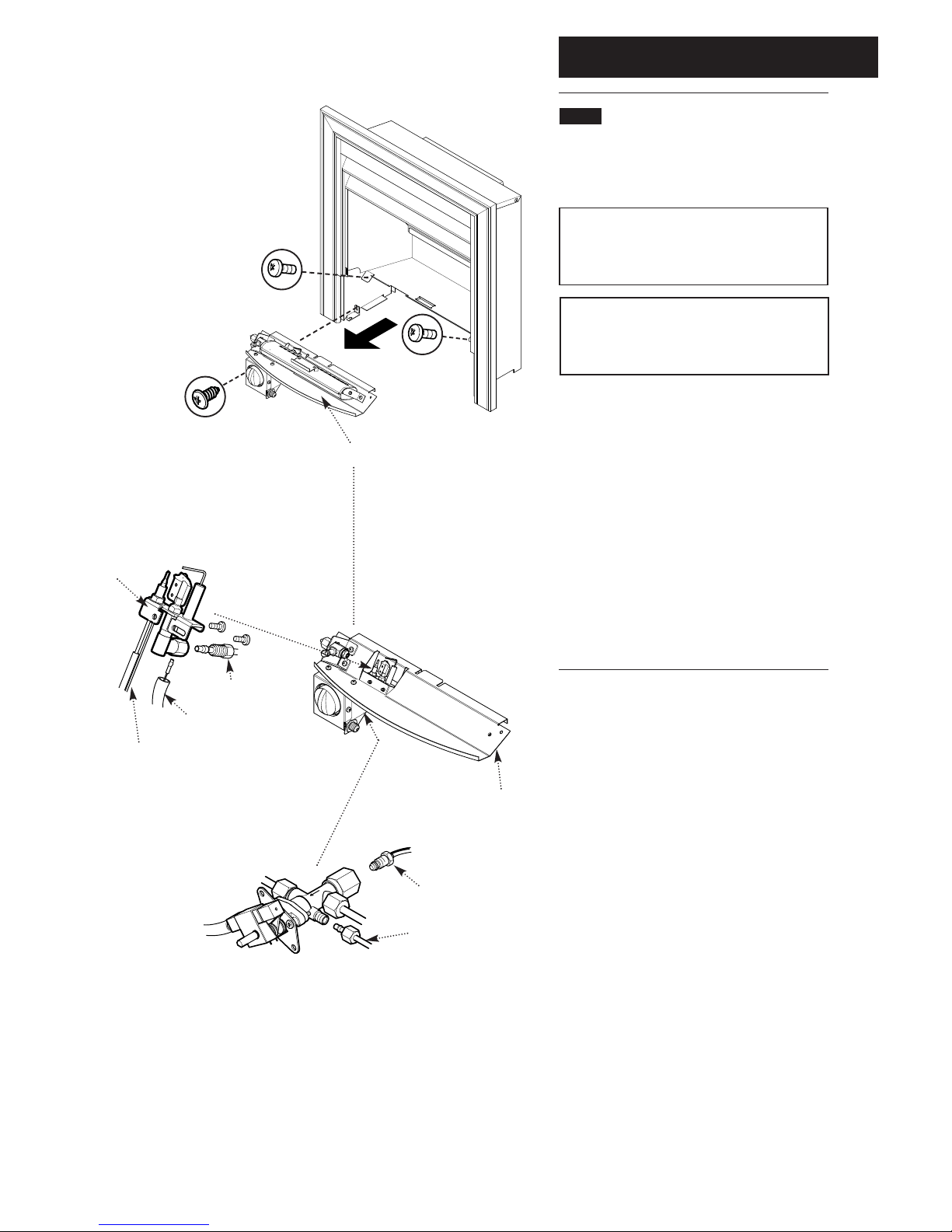
9.3 Pilot/A.S.D. Assembly
1. Undo the three retaining screws and remove
the controls assembly from the fire combustion
box (Fig. 48).
NOTE: On refitting the controls assembly,
ensure that the tongue on the controls
mounting plate engages in the corresponding
slot in the combustion box lower panel.
NOTE: The thermocouple cannot be changed
as an individual component. The complete
assembly must be replaced in the event of
one or other component failure(s).
2. Disconnect the electrode lead from the
electrode (Fig. 49).
3. Undo the thermocouple nut from the base of
the gas tap and disconnect the pilot feed pipe
from the tap body and pilot/A.S.D. assembly
(Figs. 49 & 50).
4. Undo the two screws holding the pilot/A.S.D.
assembly to the controls mounting plate and
remove (Fig. 49).
5. Shape the thermocouple of the replacement
pilot/A.S.D. assembly in a similar manner to the
original and fit in reverse order.
Pilot Feed Pipe
Electrode Lead
Pilot/A.S.D.
Assembly
Thermocouple Nut
Pilot Feed Pipe
Gas Tap
Controls Mounting Plate
Thermocouple
Fig. 49
Fig. 50
Controls Assembly
Fig. 48
Page 20
9.0 Changing Components
20
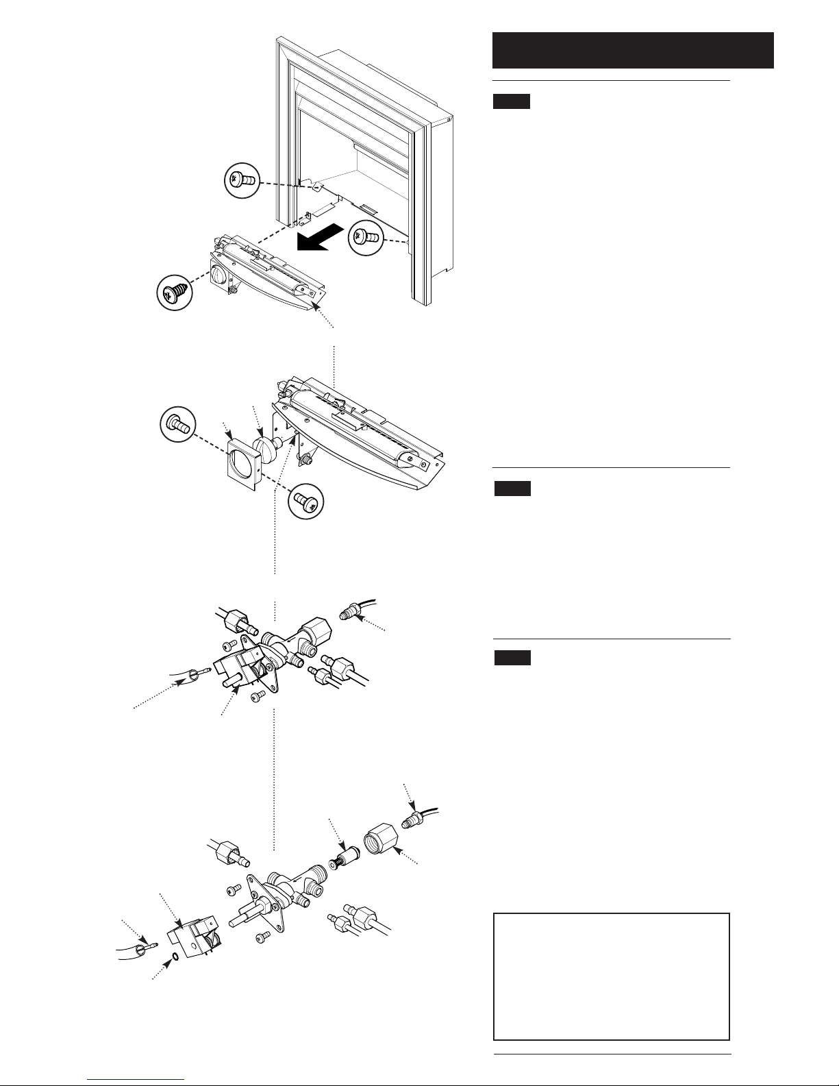
9.4 Gas Tap
1. Undo the three retaining screws and remove
the controls assembly from the fire combustion
box (Fig. 51).
2. Undo the two screws holding the bezel to the
gas tap bracket. Remove the bezel and control
knob (Fig. 52).
3. Undo the thermocouple nut from the base of
the gas tap, and disconnect the three gas pipes
from the tap body (Fig. 53).
4. Disconnect the electrode lead from the igniter
unit (Fig. 53).
5. Undo the two screws holding the gas tap to its’
bracket. Remove the tap, slackening the gas
pipes at their other connections if necessary
(Fig. 53).
6. Fit the new tap in reverse order.
9.5 Igniter Unit (Fig. 54)
1. Remove the gas tap as described above.
2. Prize the circlip off the tap control shaft. Draw
the igniter unit off the shaft and replace with the
new one.
3. Fit the new circlip.
9.6 Electro-Magnetic Unit (Fig. 54)
1. Undo the three retaining screws and remove
the controls assembly from the fire combustion
box (Fig. 51).
2. Undo the thermocouple nut from the gas tap.
3. Undo the electro-magnetic unit retaining nut
and withdraw the unit.
4.Fit the new unit and replace the nut.
After changing components replace all the
coals, side cheeks, back piece and underbed
as described in “Arranging the Coals”.
CAUTION:
The coals are extremely fragile
and must be handled accordingly. Gloves
should be worn and any inhalation of the dust
should be avoided. Keep the coals away from
children at all times. Never use coals other
than those originally supplied or Genuine Baxi
Spare Parts. Never put additional coals on the
fire.
Electrode
Lead
Igniter Unit
Thermocouple
Nut
Bezel
Control
Knob
Gas Tap
Assembly
Thermocouple
Nut
Igniter Unit
Electrode
Lead
Circlip
Electro-Magnetic
Unit
Retaining
Nut
Fig. 52
Fig. 53
Fig. 54
Controls Assembly
Fig. 51
Page 21
10.0 Fault finding
21
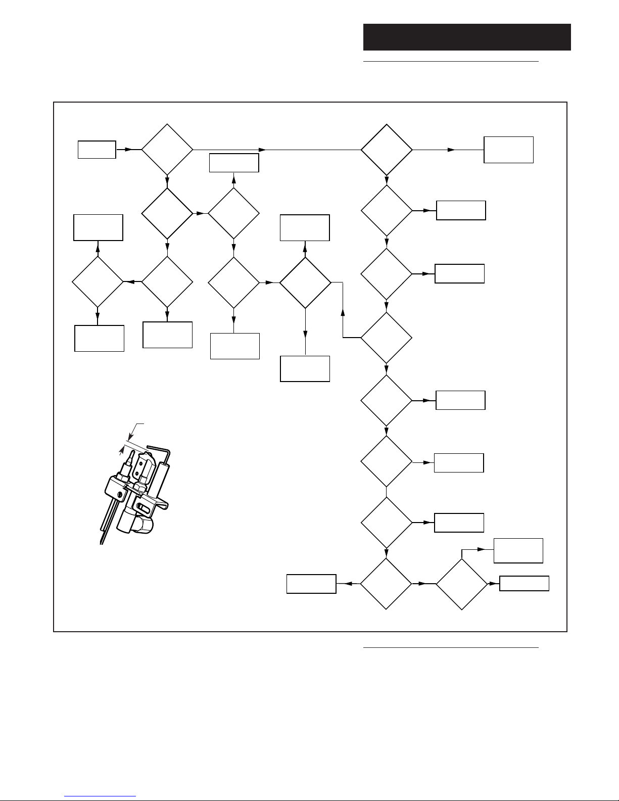
Fault Finding
Does
the fire
ignite ?
Does
the fire
remain
alight
Are
gas cocks
fully open ?
Is
pilot burner
clean ?
Is flue
blocked causing
A.S.D. to
operate ?
Is
spark gap
(2.5 to 4mm)
Is
the spark
igniter
firing ?
Is
gas supply
turned
on ?
START
Check electrode
lead and
insulation
Change
igniter
Correct
spark gap
(see diagram)
Clean
pilot burner
YES
YES
NO
YES
Is
meter
pressure
correct ?
(20mb)
Consult the
Gas Supplier
Turn on
gas supply
NO
NO
Fire
operating
satisfactorily
YES
YES
NO
NO
NO
YES
NO
YES
NO
YES
YES
NO
Is
there a
spark at
electrode
NO
Internal pilot filter
blocked -
replace gas tap
Is
meter pressure
correct ?
YES
Are
pilot flames
stable and approx
20mm long
YES
Is
thermocouple
tip clean ?
YES
Is
thermocouple
tip sound ?
YES
Is
thermocouple
output within
limits ?
NO
Change
pilot assembly
Change the
electro-magnetic
unit
Rectify flue
NO
YES
Open
gas cocks
Contact the
Gas Supplier
Clean
thermocouple tip
Change
pilot assembly
NO
YES
NO
NO
Is
thermocouple
connection
sound ?
Make good
the connection
NO
YES
Pilot/A.S.D.
Assembly
2.5 - 4mm
Page 22
10.0Short parts list
22
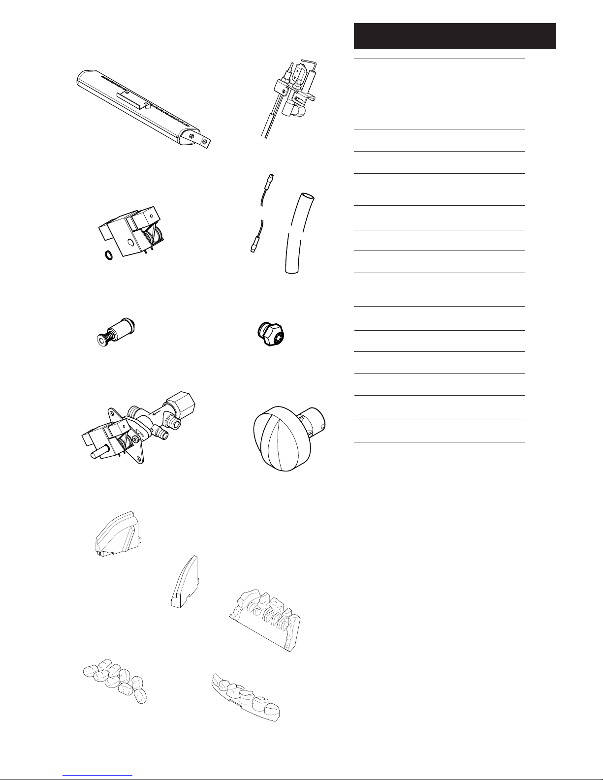
Short Parts List
Key G.C. Description Manufacturers
No. No. Part No.
9 E25 260 Gas Tap/FFD Assy 244950
10 E01 353 Spark Generator 239289
11 E01 617 Electro Magnetic 239413
Unit
13 156 347 Knob Control 236295
14 E60 865 Burner Assy 247238
20 379 914 Oxypilot SIT OP 9402 238087
23 E06 212 Injector Multi-hole 243038
Steromatic F15
25 378 924 Electrode Lead 236493
26 E01 367 Sleeve-Electrode 227051
32 E65 281 Side Cheeks 248555
34 E60 875 Rear Coal 247607
35 E59 197 Coals Loose Pack of 9 247327
36 E60 876 Front Coal 247608
11
26
25
14
20
9
10
23
13
32
34
35
36
Page 23

Baxi UK Limited manufacture a comprehensive
range of products for the domestic heating market
Gas Central Heating Boilers
(Wall, Floor and Fireside models).
Independent Gas Fires.
Renewal Firefronts.
Gas Wall Heaters.
Solid Fuel Fires.
If you require information on any of these products,
please write to the Sales Department.
23
Page 24

Baxi UK Limited
Brownedge Road
Bamber Bridge Preston
Lancashire
PR5 6SN
www.baxi.com
After Sales Service
08706 096 096
Technical Enquiries
08706 049 049
Comp No247612 - Iss 3 - 9/01
 Loading...