

Page 1

Baxi Bermuda 45/4 & 57/4 Boilers
Gas Fired Central Heating Unit
Gas Type G20 (Natural Gas)
Comp N
Baxi Bermuda 45/4 M - G.C.No 44 077 71
Baxi Bermuda 57/4 M - G.C.No 44 077 72
Baxi Bermuda 45/4 E - G.C.No 44 077 73
Baxi Bermuda 57/4 E - G.C.No 44 077 74
These Instructions must be read in conjunction with those
for the separate Firefront.
o
241794 - Iss 9 - 6/00
Installation
And
Servicing
Instructions
Page 2

Natural Gas
Baxi Bermuda 45/4 M
G.C.No. 44 077 71
Baxi Bermuda 57/4 M
G.C.No. 44 077 72
Baxi Bermuda 45/4 E
G.C.No. 44 077 73
Baxi Bermuda 57/4 E
G.C.No. 44 077 74
These Instructions must be read in
conjunction with those for the
separate Firefront.
Baxi UK Limited is one of the leading manufacturers
of domestic heating products in the UK.
Our first priority is to give a high quality service to our
customers. Quality is built into every Baxi product -products
which fulfil the demands and needs of customers, offering
choice, efficiency and reliability.
To keep ahead of changing trends, we have made a
commitment to develop new ideas using the latest
technology - with the aim of continuing to make the products
that customers want to buy.
Baxi is also the largest manufacturing partnership in the
country. Everyone who works at the company has a
commitment to quality because, as shareholders, we know
that satisfied customers mean continued success.
We hope you get a satisfactory service from Baxi. If not,
please let us know.
Baxi is a BS-EN ISO 9001
Accredited Company
The boiler meets requirements of Statutory Instrument “The
Boiler (Efficiency) Regulations 1993 No 3083” and is
deemed to meet the requirements of Directive 92/42/EEC on
the efficiency requirements for new hot water boilers fired
with liquid or gaseous fuels.
Type test for purpose of Regulation 5 certified by:
Notified Body 0086.
Product/production certified by: Notified Body 0086.
Page 3

CONTENTS - Page 3
Introduction
Technical Data
System Details
Site Requirements
PAGE 4
PAGE 5
PAGE 6 - 8
Water Circulating Systems
Treatment of Water Circulating Systems
Pipework
System Controls
Fully Pumped System
Overheat Kit & Sealed Systems
Storage Systems
Pumped Heating & Gravity Hot Water
PAGE 9 - 12
Builders & Fireplace Opening
Location
Fireplace Surround
Flue
Ventilation
Gas Supply
Electrical Supply
Installation
Commissioning the Appliance
Annual Servicing
Changing Components
Short Parts List
Fault Finding
PAGE 13 - 22
Initial Preparation
Siting the Boiler
Securing the Boiler
Water Connections
Fully Pumped Systems
Overheat Thermostat
Pumped Heating & Gravity Hot Water
Gas Connection
Electrical Connection
Making the Electrical Connection
Refilling the Controls
Flue Connection
Completion
PAGE 23 - 24
PAGE 25 - 28
Removal of Firefront
Removal of Controls
Cleaning the Lint Arrestor
Cleaning the Burner & Main Injector
Cleaning the Pilot / A.S.D. Assembly
Cleaning the Heat Exchanger
PAGE 29 - 34
Removal of Firefront
Flame Sensing Lead
Ignition Lead
Gas Valve
Burner & Main Injector
Pilot / A.S.D. Assembly
Thermostat
Piezo Igniter Unit
Suppression Capacitor
Thermostat Sensor
Thermostat Potentiometer
Printed Circuit Board
PAGE 35
PAGE 36 - 40
Page 4

INTRODUCTION - Page 4
Description
The Baxi Bermuda is a combined central heating boiler and
gas fire designed for installation within a builders opening in
the living space of a dwelling.
These installation and servicing instructions cover all natural
gas models. There are two physical sizes of boiler, the
Bermuda 45 being the smaller. Both Bermuda 45 and 57 are
available with either electronic or manual controls. The
appliance is fitted with an Atmospheric Sensing Device
which will shut the boiler down in the event of adverse flue
conditions. All installation and servicing procedures are the
same for each size of boiler. Any differences in procedure
between electronic and manual control versions are covered
in this booklet.
These instructions relate to the central heating boiler section
of the appliance.
The two models of the boiler have range rated outputs
as shown.
Each appliance is preset at its MIDRANGE heat input rate
and is designed for use on NATURAL GAS only. The boilers
are suitable for fully pumped and pumped central heating
with gravity hot water systems. The propane back boiler is
covered by its own instructions supplied with it. An optional
overheat thermostat kit is available for sealed systems or
where additional system protection is required.
“Benchmark” Log Book
As part of the industry-wide “Benchmark” initiative all Baxi
boilers now include an Installation, Commissioning and
Service Record Log Book. Please read the Log Book
carefully and complete all sections relevant to the appliance
and installation. These include sections on the type of
controls employed, flushing the system, burner operating
pressure etc. The details of the Log Book will be required in
the event of any warranty work. Also, there is a section to be
completed at each subsequent regular service visit.
Baxi Part No 235565 for 45/4E & 57/4E
Baxi Part No 234885 for 45/4M & 57/4M
Installation
The installation must be carried out by a CORGI Registered
Installer or other Competent Person and be in accordance
with the relevant requirements of GAS SAFETY (Installation
and Use) REGULATIONS, the BUILDING REGULATIONS
(Scotland) (Consolidation), the LOCAL BUILDING
REGULATIONS, the current I.E.E. WIRING REGULATIONS
and the bye laws of the LOCAL WATER UNDERTAKING.
Where no specific instructions are given, reference should
be made to the relevant B.S. CODES OF PRACTICE.
All systems must be thoroughly flushed and treated with
inhibitor (see System Details).
B.S. Codes of Practice
STANDARD
BS 6891
BS 5546
BS 5449
BS 6798
BS 5440 Pt 1
BS 5440 Pt 2
BS 5871 Pt 1
BS 6500
SCOPE
Gas Installation.
Installation of hot water supplies
for domestic purposes.
Forced circulation hot water
systems.
Installation of gas fired hot water
boilers.
Flues.
Air Supply.
Installation of fire/back boilers,
gas appliances.
Cables
Page 5

TECHNICAL DATA - Page 5
Bermuda Boiler 57/4
Bermuda Boiler 45/4
Sedbuk Declaration For Bermuda
45/4 and 57/4 Boilers
The seasonal efficiency (SEDBUK) are
45/4M 72.7%
45/4E 76.8%
57/4M 71.8%
57/4E 75.8%
This value is used in the UK
Government’s Standard Assessment
Procedure (SAP) for energy rating of
dwellings. The test data from which it
has been calculated has been certified
by 0086.
Page 6

SYSTEM DETAILS - Page 6
Water Circulating Systems
The appliance is suitable for open vented systems which are
either fully pumped or pumped central heating with gravity
domestic hot water.
An overheat thermostat modification kit is available where
additional control protection is required and for sealed
system applications. This must not be used on gravity
systems
The following conditions should be observed at all
times:
The static head must not exceed 30m (100ft) of
water.
The boiler must not be used with a direct cylinder.
Drain cocks should be fitted to all system low points.
All gas and water pipes and electrical wiring must
be installed in such a way that it does not restrict the
servicing of the boiler. Position isolating valves as
close as possible to the circulating pump
Treatment of Water Circulating Systems
For optimum performance after installation, this boiler and its
associated central heating system must be flushed in
accordance with the guidelines given in B57593: 1992
‘Treatment of water in domestic hot water central heating
systems’.
This must involve the use of a proprietary cleanser, such as
BetzDearborn’s Sentinel X300 or X400, or Fernox’s
Superfloc. Full instructions are supplied with the products,
but for immediate information, please contact BetzDearborn
on 0151 420 9563, or Fernox on 01799 550811.
For long term protection against corrosion and scale, after
flushing, it is recommended that an inhibitor such as
BetzDearborn’s Sentinal X100, or Fernox’s MB-1 or Copal is
dosed in accordance with the guidelines given in B5S593:
1992.
Failure to flush and add inhibitor to the system may
invalidate the appliance warranty.
Pipework
The sizes of the flow and return pipes from the boiler should
be determined by normal methods according to the
requirements of the system (BS 5449).
It is recommended that the system is designed for an
11ºC (20ºF) drop in temperature across the system.
In systems using non-metallic pipework it is necessary to
use copper pipe for the boiler Flow and Return. The copper
must extend at least 1 metre from the boiler and include any
branches. The copper pipe must not be insulated (Fig. 1).
Page 7

SYSTEM DETAILS - Page 7
System Controls
For optimum operating conditions, the heating system into
which the appliance is installed should include a control
system.
Such a system would comprise a timer control and a
separate room and/or cylinder thermostat as appropriate.
The boiler should be controlled so that it operates on
demand only.
It is not economical to rely on the boiler thermostat to
control operation of the system.
Fully Pumped System
The sizes of the system pipes should be determined by
normal methods (BS 5449).
The open vent pipe should be a minimum of 22mm and must
rise continuously to a point above the feed and expansion
tank.
The flow pipe from the boiler may form part of the vent pipe.
No part of the open vent should contain a valve.
The cold feed pipe (15mm mm) should preferably be
connected to the boiler return.
Close coupling of the cold feed pipe to the flow pipe at a
maximum of 150mm (6 in) from the vent pipe is permissible
but there must always be an open cold water path to the
boiler return connection.
Page 8

SYSTEM DETAILS - Page 8
Overheat Kit And Sealed Systems
An overheat thermostat modification kit is available to
facilitate the installation of a Bermuda boiler to systems
incorporating a combined feed and vent and to flats and
dwellings where the building design prevents the boiler vent
pipe rising continuously to the feed and expansion tank.
(This must not be used on gravity systems.)
Baxi Part No 235565 for Electronic Controls
Baxi Part No 234885 for Manual Controls
The boiler can be applied to a sealed system with the
use of the overheat kit.
Information regarding the application of the overheat
thermostat is included with the kit.
Storage Systems
For information regarding the use of a Bermuda boiler with.a
storage system, contact the appropriate storage system
manufacturer.
Pumped Heating & Gravity Hot Water
The sizes of system pipes should be determined by normal
methods (BS 5449). 28mm pipe is recommended for the
gravity circuits.
The gravity flow pipe should rise vertically as close as
possible to the boiler, avoiding sharp bends and tight
elbows.
The open vent pipe should be a minimum of 22mm and must
rise continuously to a point above the feed and expansion
tank.
The flow pipe from the boiler may form part of the vent pipe.
No part of the open vent should contain a valve.
The cold feed pipe (15mm mm) should be connected to the
boiler return pipework.
The brass injector tee must be fitted to the boiler return
on all systems incorporating a gravity circuit.
The circulating head should not be less than 1 m (3ft.) with a
maximum horizontal run of 3m (10ft.) when using 28mm
pipes. Smaller pipe sizes and longer horizontal runs are
acceptable with suitably increased circulating heads.
The gravity circuit should be designed with a minimum of
restriction, avoiding possible air traps and long horizontal
runs.
The system should be designed to prevent gravity circulation
in the heating system when the pump is not running.
Page 9

SITE REQUIREMENTS - Page 9
Builders & Fireplace Opening
The boiler unit is designed to fit within a standard builders
opening cavity, the minimum dimensions of which are
343mm(13½in) deep x 584mm(23in) wide x 584mm(23in)
high.
The opening should be soundly constructed of brick, precast concrete or be a proprietary builders opening. The base
of the opening should be sound and non-combustible and
must be flat and level.
The base of the builders opening should be at the same
height as the finished level of the hearth or be the required
height of 100-125mm (4-5 in) above floor level for a wall
mounted firefront installation.
The fireplace opening (i.e. the opening into the cavity) must
be 560mm (22in) high and between 406mm (16in) and
584mm (23in) wide.
Maximum fireplace opening sizes are preferable for ease of
installation and service.
Location
The appliance must be installed in the living space of a
dwelling.
Restrictions to the siting of the appliance are covered by BS
5546. The appliance may not be installed in bathrooms,
shower rooms, bedrooms or bed sitting rooms.
Fireplace Surround
If a fireplace surround is to be used, it must be centrally
placed and have opening sizes and a vertical flat area as
shown in the firefront Installation and Servicing Instructions.
Maximum fireplace opening sizes are preferable for ease of
installation and service.
NO SURROUND
The appliance can be fitted without a surround.
The fireplace opening and vertical flat areas as per above
still apply.
Maximum fireplace opening sizes are preferable for ease of
installation and service.
HEARTH MOUNTING
All Bermuda Firefronts are suitable for hearth mounting. The
hearth must be on the same level as the builders opening.
The hearth must be non-combustible and comply with BS
5871: Pt 1.
WALL MOUNTING
A number of Bermuda Firefronts are aesthetically suitable for
wall mounting above the level of the room floor in instances
where there is no hearth.
The base of the builders opening on which the boiler rests
should be 100-125mm (4-5 in) above floor level.
The following firefronts are suitable for wall mounting:
Bermuda 5P3 Bermuda PW5 Deluxe
Bermuda CS Bermuda RG3
Bermuda C5W Bermuda LFE5 Super
Page 10

SITE REQUIREMENTS - Page 10
FLUE
Prior to installation it is important to establish that the
flue will perform satisfactorily. Do not proceed with the
installation if the flue does not operate correctly.
The Bermuda is fitted with an Atmospheric sensing
Device that will automatically shut the appliance down
under adverse flue conditions and where insufficient
flue pull exists.
The flue installation must conform to BS 5440 Pt 1. The flue
must have a minimum vertical height of 3m (10ft) measured
from the boiler flue outlet socket and have an internal cross
section area of 12,700 mm2 (20in2), this is satisfied by a flue
of 125mm (5in) internal diameter. If the flue system contains
any bends the vertical height must be increased accordingly.
An approved terminal is required for all installations.
9in X 9in BRICK
Flues previously used for other fuels must be thoroughly
swept. The flue must be protected with a 125mm (5in)
flexible liner. The bottom of the liner should terminate
500mm (20in) above the base of the builders opening. The
flue must be sealed between the liner and the brickwork at
both the top and bottom.
An approved terminal must be installed.
ACID RESISTANT LINERS
A flue constructed of acid resistant liners is satisfactory
provided the size requirements are met.
The boiler flue outlet can be connected to the flue by
means of a short length of 125mm (5in) of flue pipe.
A seal must be made in the annular space between the outer
face of this flue pipe and the acid resistant liner.
An approved terminal must be installed.
PRECAST FLUES
These must conform to BS 5440 Pt 1 and be correctly
designed and installed without intrusion of cement into the
flue passage.
An approved terminal must be installed.
PROPRIETARY FLUES
A flue of this type must meet the size requirements specified
and be installed in accordance with the flue manufacturers
recommendation and relevant codes of practice.
An approved terminal must be installed.
Page 11

SITE REQUIREMENTS - Page 11
Ventilation
Ventilation air supply to BS 5440 Pt 2 is required.
The permanent ventilation area size requirements are
given in the firefront Installation and Servicing
Instructions.
The permanent vent may be directly into the room containing
the appliance. The vent may also be sited in another room
provided an interconnecting vent is used.
The vent must not be installed inside the builders opening.
The vent should be sited following good practise for a
habitable room. We recommend the use of the Stadium
BM720 “Black Hole” ventilator which is available from your
local merchant.
Gas Supply
The gas installation should be in accordance with BS
6891. The connection at the appliance is Rc ½ (½in
BSPT internal) located at the rear of the gas cock.
Ensure the pipework from the meter to the appliance is of
adequate size and suitably protected. It is preferable to route
the gas supply pipe to the right hand side of the builders
opening. It must be routed so as not to restrict the
installation and servicing of the appliance.
Electrical Supply
External wiring must be correctly earthed, polarised and in
accordance with current lEE wiring regulations. The mains
supply is 230V ~ 50Hz
fused at 5 A.
NOTE: The method of connection to the electrical
supply must facilitate complete electrical isolation of the
appliance, connection may be made via a fused double
pole isolator with a contact separation of at least 3mm
on all poles and serve the appliance and system
controls only.
The cable within the builders opening should be 0.75 mm2 to
lEC 53 Code 227 (heat resistant).
The cable must be routed to avoid contact with the
metal combustion box and hood.
PERMANENT LIVE
A permanent live electrical supply is required for all firefronts
with lighting effects i.e. VP3, 5P3, RG3, 5L3, LFE5 Super
and GF3 Super. The permanent live is also required to
operate the electronic ignition on VP3, 5P3 and RG3
models.
Page 12

SITE REQUIREMENTS - Page 12
Functional Flow Diagram
It is preferable to route the input cable from the left hand side
of the builders opening.
The cable can be secured to either the boiler base or fire
support plate using the ‘P’ clip supplied in the kit.
NOTE: Polarity of the appliance MUST be correct otherwise
the appliance will not operate correctly.
Page 13
INSTALLATION - Page 13
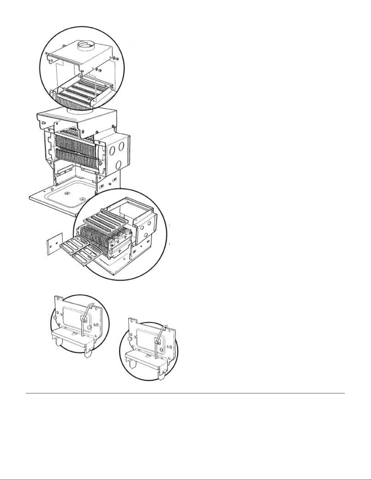
Initial Preparation
Remove the outer carton and locate the fitting kit. Remove
and discard the packing pieces and unpack the boiler hood.
The hood may be fitted now or when the boiler is in situ. Use
the four nuts and set screws provided.
Remove the controls heat shield from its retaining clips.
Remove the four screws retaining the combustion box door
and remove the door.
Slacken the two screws holding the controls to the boiler
base. Remove the two screws retaining the controls to the
combustion box and remove the controls.
The boiler as supplied has the flow and return water
connections at the left hand side of the appliance.
For installations requiring the water connections at the
right hand side proceed as follows:
(This operation is performed most easily with the boiler on its
back).
Lift out the 3 heat exchanger baffles, noting their orientation.
Lift the heat exchanger from the appliance and remove the
side blanking plate.
Transfer the 3 sealing rings from the holes in the left hand
side of the boiler to those in the right.
Rotate the heat exchanger to place the water connections at
the right hand side, return the
heat exchanger to the combustion box.
DO NOT TURN THE HEAT EXCHANGER UPSIDE DOWN
NOTE: The heat exchanger is correctly oriented when the
three water connections line up with the holes in the right
hand side of the combustion box and the thermostat pocket
aligns with the corresponding hole in the door. The unfinned
heat exchanger water tubes face the burner.
Remove the blanking disc from the left hand hole in the
boiler door and the rubber seal from the right hand hole and
swap them over.
Replace the heat exchanger baffles and blanking plate.
Page 14
INSTALLATION - Page 14
Siting the Boiler
The fireplace and builders opening should be as described
under ‘site requirements’ and be clean, sound and level.
The flue should be installed as described under ‘site
requirements’.
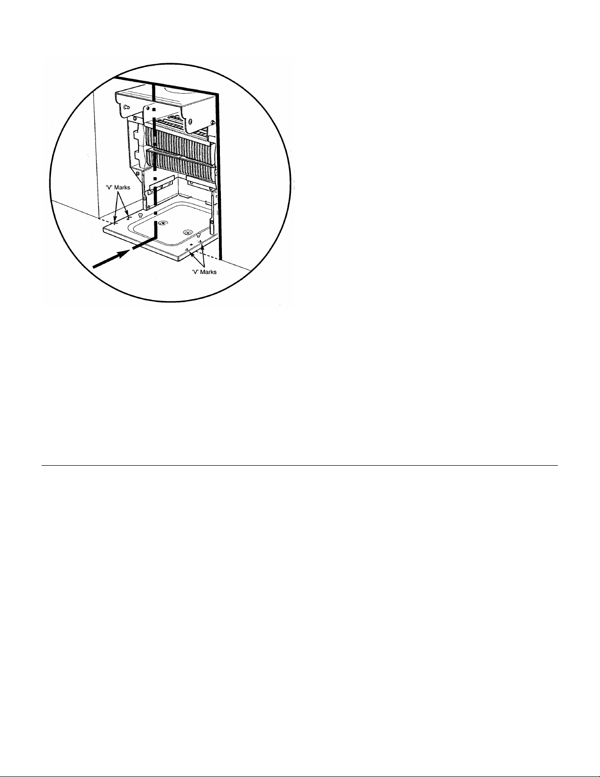
Locate the centre line of the opening and hearth.
Hold the boiler by its combustion box at either side of the
heat exchanger, lift from the packing base and place into the
opening.
Align the boiler centrally using the “V” mark on the front
centre of the appliance base.
The appliance positioning into the opening is variable to
cater for pipe/flue alignment.
The boiler may be positioned by locating the front face of the
fireplace anywhere between the two “V” marks on either side
of the appliance base.
Securing The Boiler
Check the alignment within the opening is correct. The
hearth should be drilled as follows:
Mark the hearth through the two holes in the base. Remove
the boiler and drill the hearth. Insert suitable plugs. Replace
the boiler.
or
Drill directly through the two fixing holes and insert the plugs.
Secure the boiler with two suitable screws.
Page 15
INSTALLATION - Page 15
Water Connections
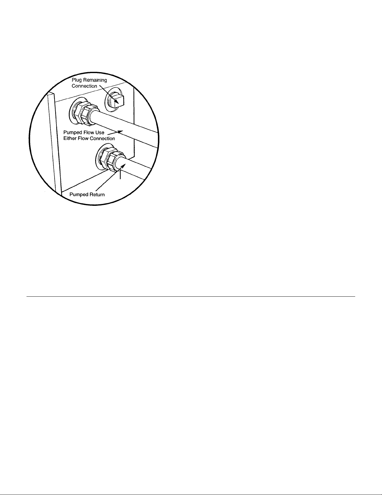
The boiler has one return and two flow tappings, Rc (1 in
BSPT). The two upper tappings are the flow connections.
The return is the lower position tapping and is marked
RETURN. It is essential the flow and return pipes are
connected to the correct tappings.
Fully Pumped Systems
A 1in x 22mm threaded adaptor, compression nut and olive
are provided in the kit for the return connection.
Fit the 1 in x 22mm threaded adaptor into the lower
tapping marked RETURN, connect the pumped return
into the adaptor using the nut and olive.
Fit a 1 in x 22mm threaded adaptor into the higher tapping
position marked FLOW, connect the pumped flow into the
adaptor.
Fit a 1 in plug to the remaining connection.
Follow the instructions under ‘System Details’
regarding the vent pipe and cold feed.
Overheat Thermostat
For systems requiring an overheat thermostat, a modification
kit is available. The flow pipe arrangement for this type of
installation is covered in the instructions supplied with that
kit.
Baxi Part No 235565 for 4514E & 57/4E
Baxi Part No 234885 for 45/4M & 57/4M
This kit is not suitable for systems where a gravity
domestic hot water circuit is used.
Page 16
INSTALLATION - Page 16
Pumped Heating & Gravity Hot Water
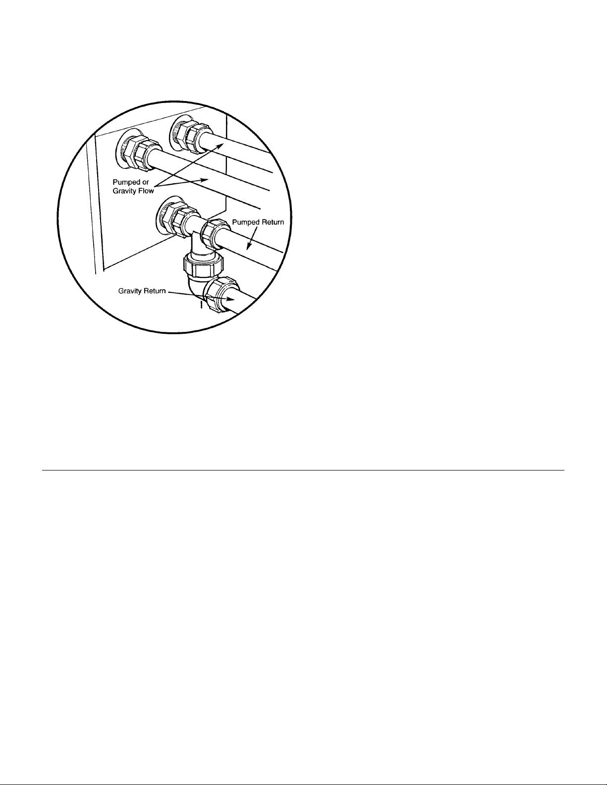
A 1in x 22mm threaded adaptor, two compression nuts and
olives and a brass injector tee piece are provided in the kit
for the return connection.
NOTE: The injector tee must be fitted to the return of all
systems with gravity domestic hot water.
Fit the 1in x 22mm threaded adaptor into the lower tapping
marked RETURN.
Fit the injector tee into the adaptor. The injector tee may be
oriented as shown to facilitate connection to the gravity
return pipework, or 45º either side of the vertically downward
plane.
Connect the pumped return to the 22mm compression fitting
of the injector tee.
Take the gravity hot water return pipe to a level beneath that
of the injector tee and connect upwards to the 28mm branch
of the injector tee, as shown.
Connect the pumped flow to the connection marked FLOW.
Connect the gravity flow to the remaining connection.
Pumped Heating
Gravity D.H.W.
The gravity flow pipes must rise vertically as close as
possible to the appliance. Ensure the pipework is routed
such that it does not introduce an airlock in the boiler.
Follow the instructions under ‘System Details’ regarding the
vent pipe and cold feed.
Gas Connection
Connection to the gas supply is Rc ½ (½in BSPT) internal
located at the rear of the gas cock.
Page 17
INSTALLATION - Page 17
Electrical Connection
The appliance requires an electrical supply from the heating
controls system. A permanent live is required for firefronts
which have electronic ignition and/or light effects.
WARNING
The appliance must be earthed. The input cable for the
appliance must be not less than 0.75mm2 to IEC 53 Code
227 (heat resistant). The system external
controls and the appliance must be supplied by the same
isolator. NOTE: The polarity of the electrical supply must
be correct otherwise the appliance will not operate.
OVERHEAT THERMOSTAT
Where an overheat thermostat modification kit is required,
the wiring instructions supplied in the kit must be followed.
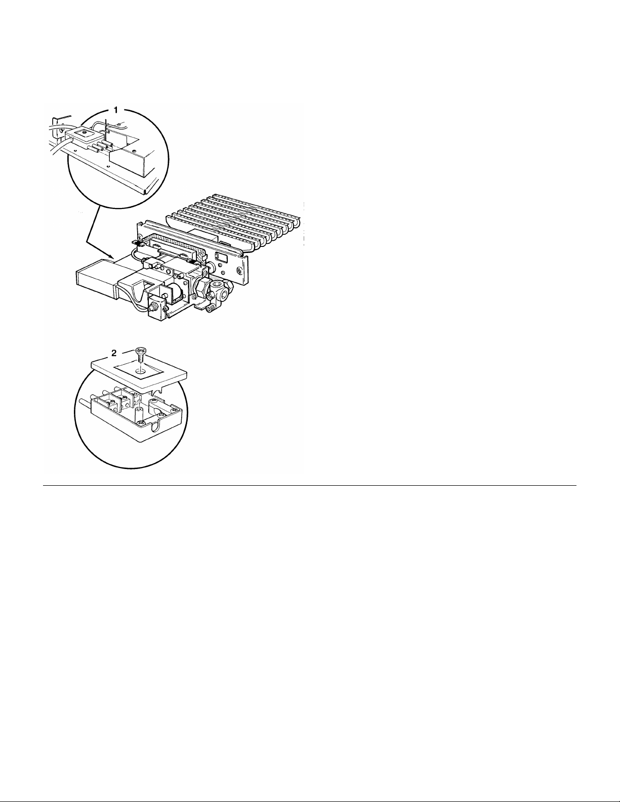
Making the Electrical Connection
On installations where the firefront requires a permanent live
locate the kit in the firefront carton and extract the electrical
lead and plug assembly.
ELECTRONIC CONTROLS MODELS
1
Remove the electrical inlet socket from the PCB at
the rear left hand side of the control box.
2
Remove the socket cover and inlet cable clamp.
Page 18
INSTALLATION - Page 18
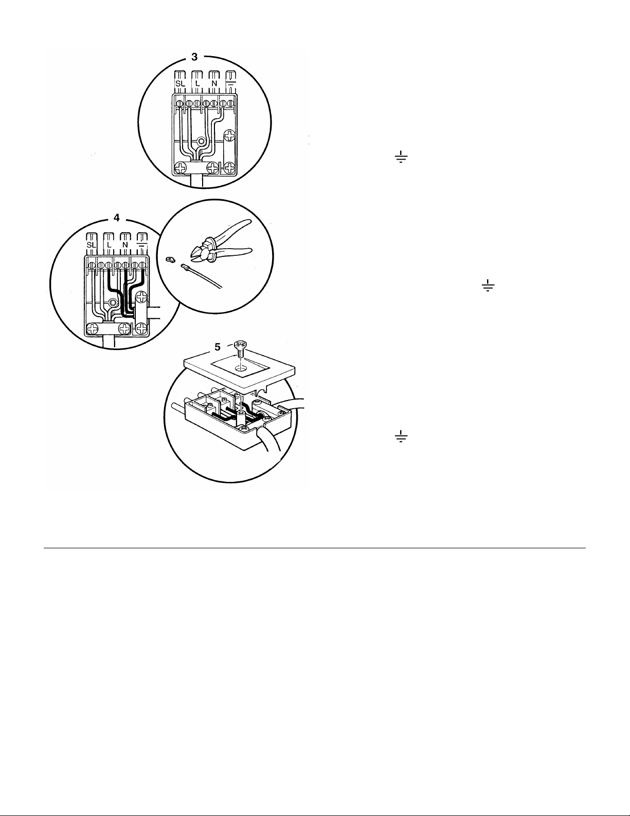
3
For installations requiring a permanent live ie:where the firefront is equipped with either lighting
effects or lighting effects and electronic ignition
proceed as follows:-
Connect the inlet supply cable(s) as indicated:-
Permanent live to L
Controls system switched live to SL
Control system neutral to N
Earth to
4
The circular part of the ring terminal on the earth wire must
be detached.
Remove the side cable clamp and connect the wire from the
fire front kit as indicated:-
Brown (live) to L
Blue (neutral) to N
Green and yellow (earth) to
5
Re-fit both cable clamps ensuring that the outer insulation is
securely held and re-fit the socket cover.
For installations not requiring a permanent live
ie: radiant fire fronts proceed as follows:Connect the inlet supply cable as indicated:-
Control system switched live to SL
Control system neutral to N
Earth to
Using the wire provided in the kit, link SL to L.
Re-fit the cable clamp ensuring that the outer insulation is
securely held and refit the socket Cover.
Ensure that all cables are routed away from the
boiler casing and hood.
Page 19
INSTALLATION - Page 19
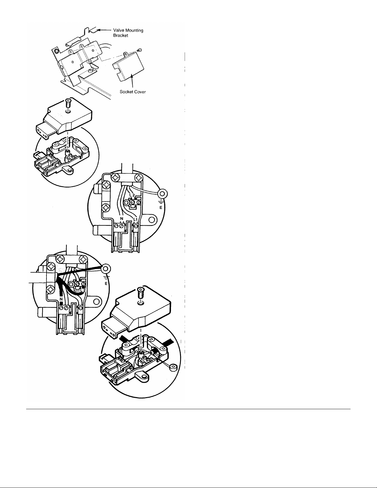
MANUAL CONTROL MODELS
NOTE: The cover must be replaced after making
electrical connections.
Undo the screw retaining the socket cover and plug and
socket to their mounting bracket.
Disconnect the input socket from the controls plug. Remove
the socket cover and inlet cable clamp.
For installations requiring a permanent live i.e. where the fire
front is equipped with either lighting effects or lighting effects
and electronic ignition, proceed as follows:-
Connect the inlet supply cable(s) as indicated:-
Permanent live to L2
Control system switched live to L1
Control system neutral to N
Route the earth through the cut out in the side of the socket
housing leaving sufficient length to connect the wire to the
earth terminal on the mounting bracket.
Remove the side cable clamp and connect the wire from the
firefront kit as indicated:
Brown (live) to L2
Blue (neutral) to N
Green &Yellow (earth) in a similar
manner to the mains earth wire.
Refit both cable clamps ensuring that the outer
insulation is securely held and refit the socket cover.
For installations where no permanent live is required i.e.
radiant firefronts, proceed as follows:
Connect the inlet supply cable as indicated:
Controls system switched live to L1
Control system neutral to N
Route the earth through the cut out in the side of the socket
housing leaving sufficient length to
connect the wire to the earth terminal on the mounting
bracket.
Refit the cable clamp ensuring that the outer insulation is
securely held and refit the socket cover.
Ensure that all cables are routed away from the boiler
casing and hood.
Page 20
INSTALLATION - Page 20
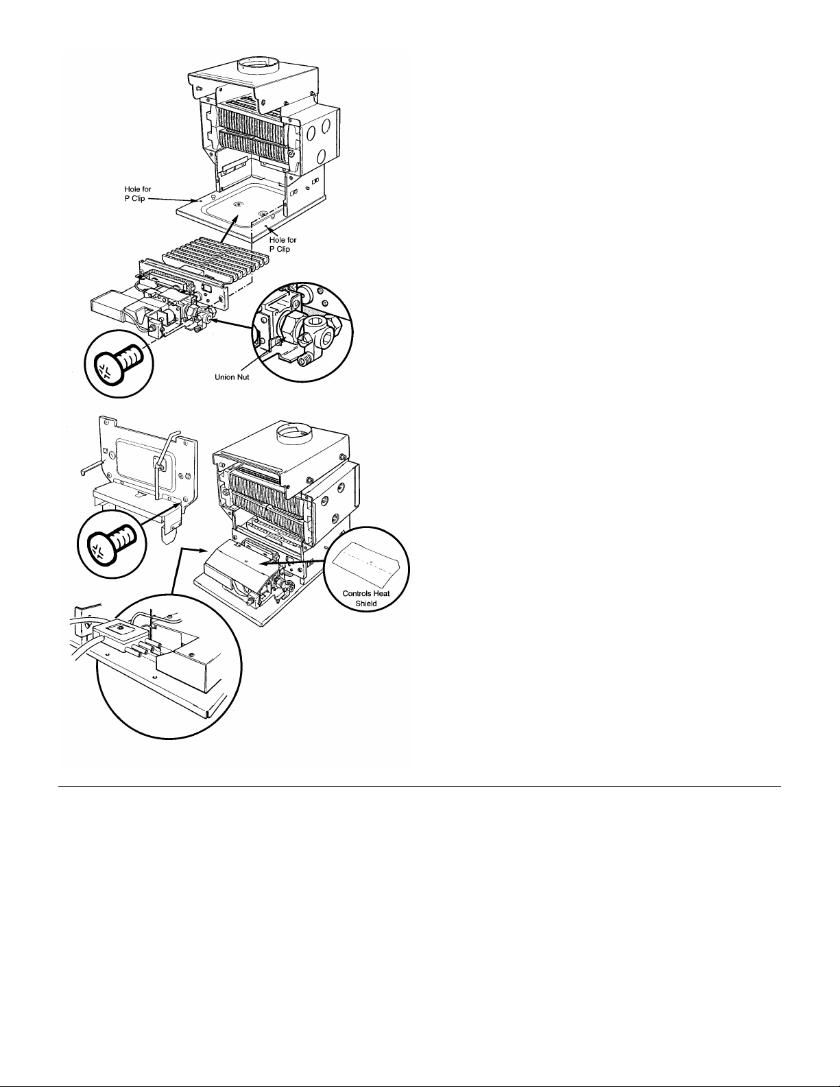
Refitting the Controls
Take the controls assembly and locate the slots in the
controls mounting bracket under the screws in the base tray.
Align the .holes in the burner mounting plate with those in
the combustion box sides and insert the screws.
Tighten the four screws.
Undo the union nut between the gas service tap and valve.
Connect the gas supply to the service tap and reconnect the
service tap to the valve. The gas supply pipe should be
routed from the right hand side. If this is not possible, it may
be routed from the left hand side, passing behind the boiler.
The positioning of the gas supply pipe must not restrict the
servicing of the appliance.
ELECTRONIC CONTROLS MODELS
Replace the combustion box door and secure with the four
screws. Ensure that the sensing pipe locates over the pilot
breather sealing washer. The screws must be tight to
achieve the required seal and to ensure correct operation of
the Atmospheric Sensing Device.
Insert the thermostat sensor and retaining strip through the
rubber seal in the door into the heat exchanger thermostat
pocket. Engage the sensor wire in the routing clips.
Connect the electrical input socket to the plug on the PCB.
Adjust the position of the thermostat potentiometer bracket.
Undo the securing screw and push fully in if a radiant fire is
to be fitted or pull out to mark “A” for flame effects.
Refit the controls heat shield to its retaining clips. If a radiant
appliance is to be installed the heat shield from the fire kit
can now be fitted.
Page 21
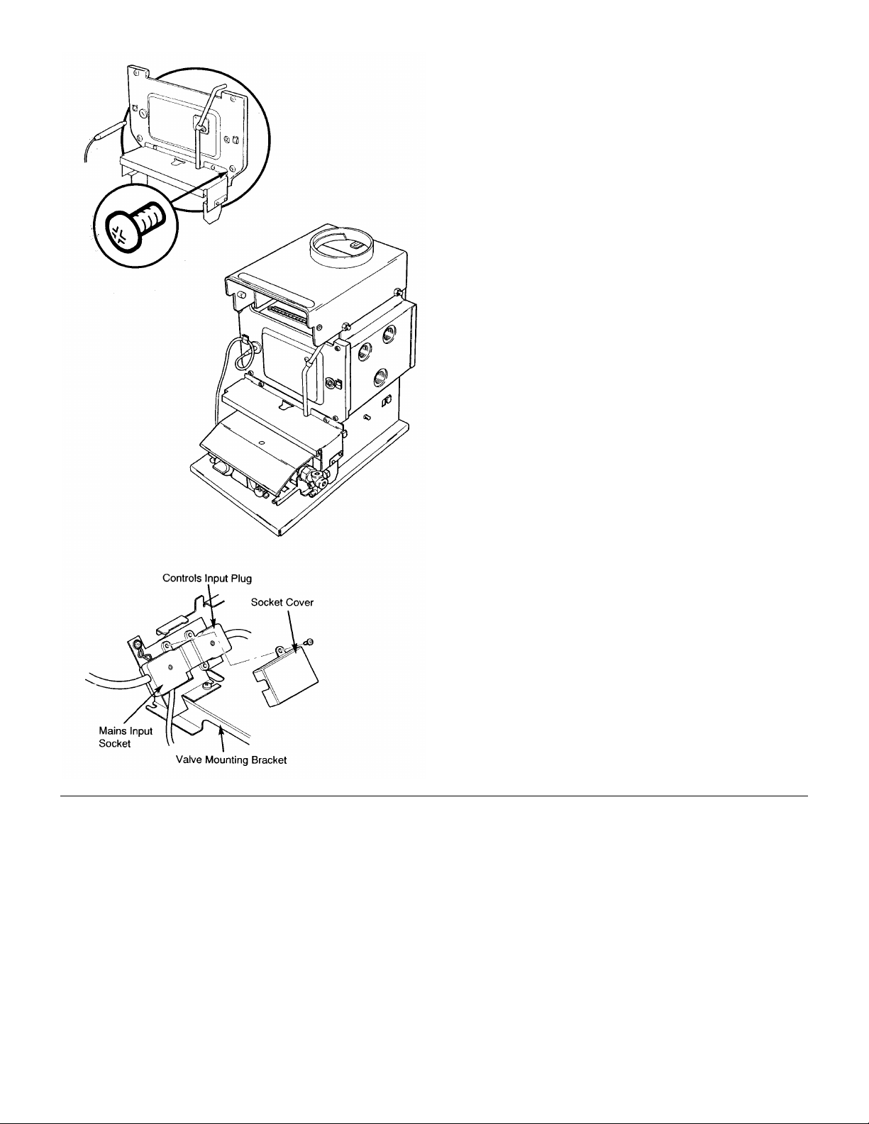
INSTALLATION - Page 21
MANUAL CONTROL MODELS
Replace the combustion box door and secure with the
screws previously removed.
Ensure that the sensing pipe locates over the pilot
breather sealing washer. The screws must be tight to
achieve the required seal and to ensure correct
operation of the Atmospheric Sensing Device.
Insert the thermostat phial through the rubber seal in the
door into the heat exchanger thermostat pocket. Engage the
capillary in the routing clips.
Connect the input socket to the valve plug and locate the
socket in the mounting bracket slot. Refit the socket cover
using the screw previously removed.
Refit controls heat shield. If a radiant appliance is to be
installed the heat shield from the fire kit can now be fitted.
Page 22
INSTALLATION - Page 22
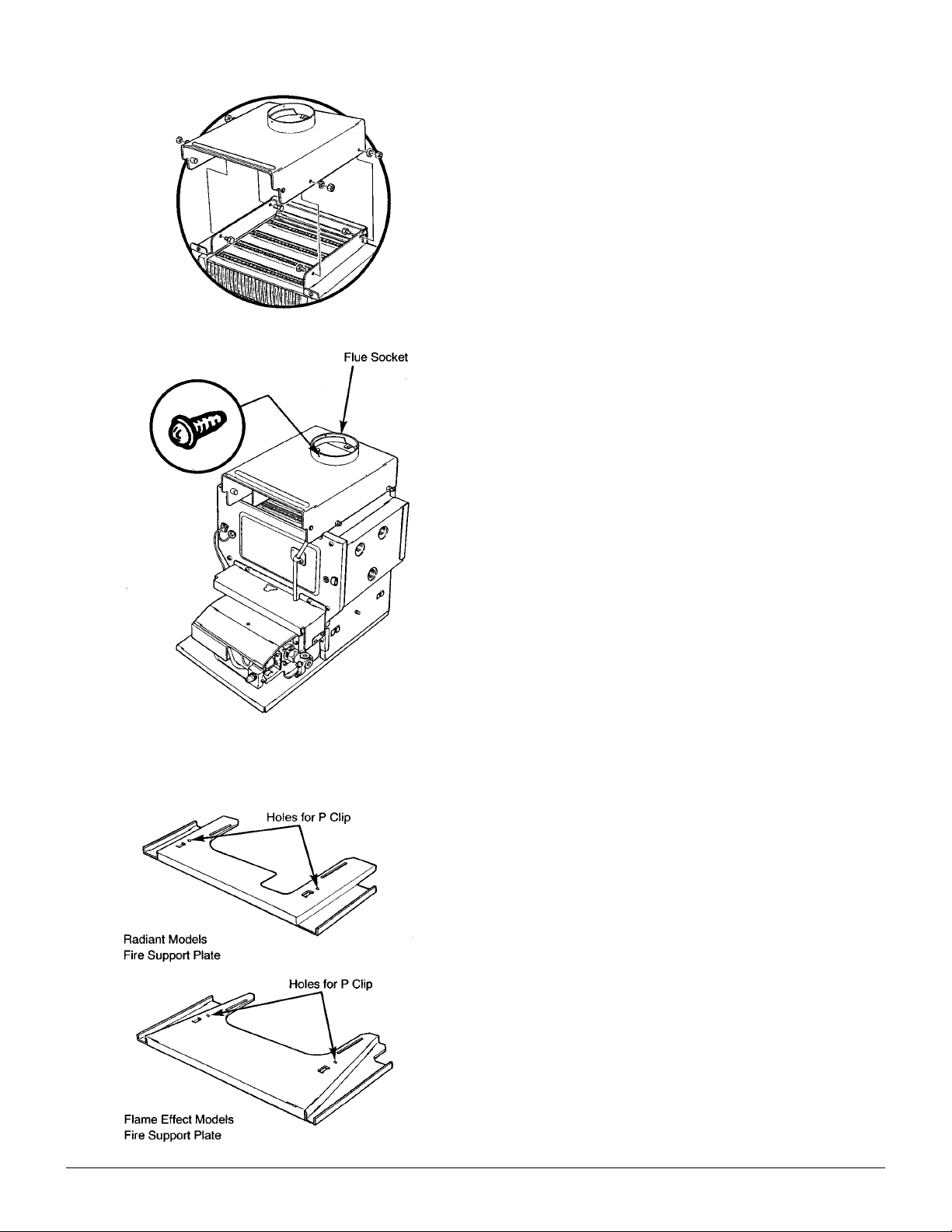
Flue Connection
If not already fitted, secure the boiler hood to the combustion
box using the 4 hexagon set screws and nuts from the kit.
Locate the flue within the flue socket and secure with
the three self tapping screws provided in the kit.
Seal the flue into the flue outlet socket.
Completion
Seal off any secondary openings within the builders opening
after wrapping the gas and water pipes where they pass
through the brickwork and within the opening itself. (B.S.
5871 Part 1).
If required (see page 12) secure the cable to the boiler using
the ‘P clip and screw to either boiler base (see page 20) or
fire support plate.
The fire support plate is supplied in the fire front carton.
Page 23
COMMISSIONING THE APPLIANCE - Page 23
Reference should be made to BS 5449 section 5 when
commissioning the boiler and system.
Flush the whole system in accordance with BS7593: 1992.
(see System Details section of these instructions). Check for
water leaks.
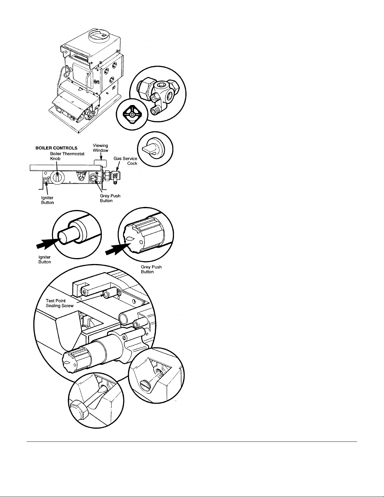
Turn the gas service cock ¼ turn from the OFF position. This
will supply gas to the boiler only.
Purge the air from the gas service pipe in accordance with
BS 6891 and test for gas soundness.
Turn the boiler thermostat to the OFF position.
Ensure that all external controls e.g. room’stat, timer etc. are
calling for heat and turn on the mains electrical supply.
Slacken the test point sealing screw and connect a pressure
gauge.
MANUAL CONTROL MODELS
Hold in the grey button on the gas control valve.
Press the piezo igniter button and release (The pilot can be
seen in the viewing window on the right hand side of the
controls). Repeat until the pilot lights. Hold in the grey button
for a further 15 seconds.
The pilot should remain alight. If not, turn the grey button
clockwise and wait 3 minutes before repeating the
sequence.
The pilot flame should be without a yellow tip and be
approximately 20mm long. No adjustment is possible.
Operate the burner by turning the boiler thermostat knob to
the HIGH setting and check the operation of the flame failure
device by turning the grey button Grey Push clockwise. The
burner and pilot should extinguish.
Turn the boiler thermostat to the “O” position, wait 3 minutes
and relight the pilot as previously described. Turn the boiler
thermostat to HIGH and check the burner setting pressure,
adjusting if necessary. This is done by removing the
governor cover screw and adjusting the governor in either
direction as required:- clockwise to increase, anticlockwise to
decrease.
Remove the pressure gauge and tighten the pressure test
point sealing screw.
The boiler and system should be run and then flushed and
treated in accordance with B57593: 1992 and the flushing
agent/inhibitor manufacturers instructions. When all the air
has been removed from the water circuit, the pump and
radiators should be balanced to achieve the design
temperature drop across the system.
Carefully read and complete all sections of the “Benchmark”
Installation, Commissioning and Service Record Log Book
that are relevant to the appliance and installation. The details
of the Log Book will be required in the event of any warranty
work. The Log Book must be handed to the user for safe
keeping and each subsequent regular service visit recorded.
Page 24
COMMISSIONING THE APPLIANCE - Page 24
ELECTRONIC CONTROLS MODELS
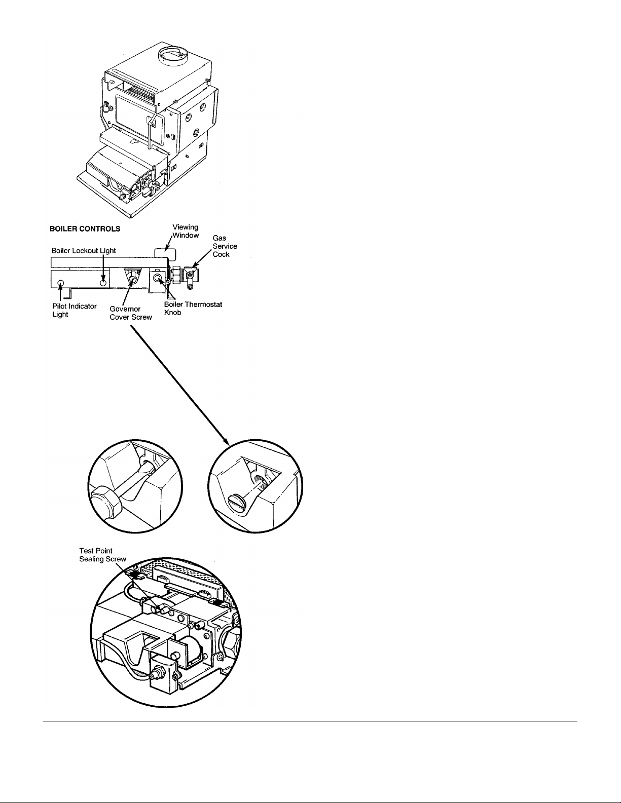
On Electronic Controls models the pilot is intermittent and
lights when the boiler thermostat is calling for heat.
To operate the pilot turn the thermostat to HIGH. The burner
will also light shortly after the pilot has been established.
Electronic Control Models are fitted with a series of
diagnostic indicator lights that indicate the status of the
boiler. Three of these are visible through the top of the
control box cover and two through the front of the control
box. Their sequence of operation is as follows:-
a) No power-no lights.
b) Permanent live supplied-orange light illuminates.
c) Permanent live & switched live supplied-second
orange light illuminates.
d) Boiler thermostat turned on-third orange light
illuminates and spark generator operates.
e) Pilot established-green light illuminates and power
supplied to main burner solenoid.
f) Boiler fault-orange light illuminates and boiler goes
to lockout.
The pilot flame should be without a yellow tip and be
approximately 20mm long. No adjustment is possible.
NOTE: On appliances without permanent live (i.e. radiant
firefront installations) where terminals L and SL have been
connected using the link wire, the first two orange lights will
illuminate simultaneously when the switched live is supplied.
Operate the burner and allow the system to reach normal
operating temperature. Make further checks for leaks and
check the burner setting pressure, adjusting if necessary.
This is done by removing the governor cover screw and
adjusting the governor in either direction as required:clockwise to increase, anticlockwise to decrease.
Remove the pressure gauge and tighten the pressure test
point sealing screw.
The boiler and system should be run and then flushed and
treated in accordance with B57593: 1992 and the flushing
agent/inhibitor manufacturers instructions. When all the air
has been removed from the water circuit, the pump and
radiators should be balanced to achieve the design
temperature drop across the system.
Carefully read and complete all sections of the “Benchmark”
Installation, Commissioning and Service Record Log Book
that are relevant to the appliance and installation. The details
of the Log Book will be required in the event of any warranty
work. The Log Book must be handed to the user for safe
keeping and each subsequent regular service visit recorded.
Page 25
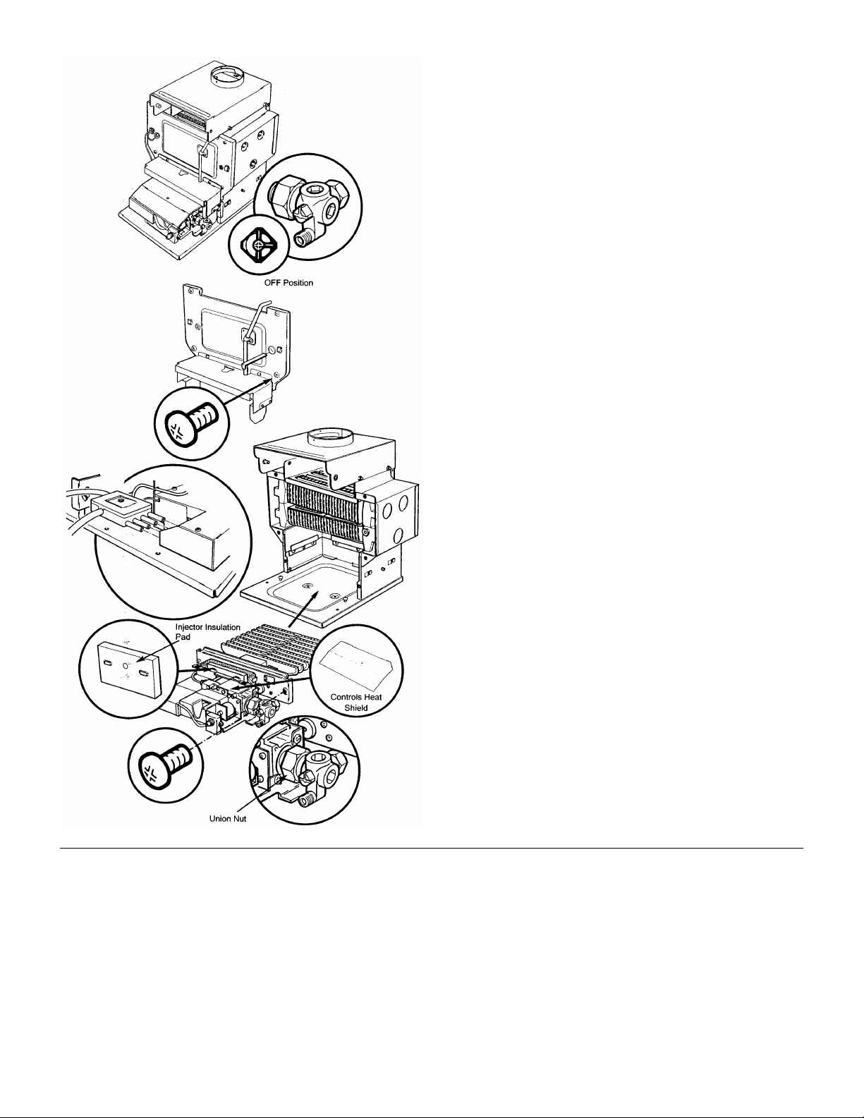
ANNUAL SERVICING - Page 25
To perform annual servicing of the back boiler it is necessary
to remove the firefront.
After servicing, complete the relevant section of the
“Benchmark” Installation, Commissioning and Service
Record Log Book. This should be in the possession of the
user.
Removal of Firefront
Isolate the electrical supply to the appliance and ensure the
permanent live (where fitted) has also been isolated.
Turn the gas service tap to the OFF position.
Refer to the separate firefront instructions for the removal of
the firefront.
Removal of Controls
ELECTRONIC CONTROLS MODELS
Remove the thermostat sensor and retaining strip from the
heat exchanger and carefully remove the sensor wire from
its routing clips.
Remove the controls heat shield from its retaining clips.
Remove the four screws retaining the combustion box door
and remove the door.
Lift and remove the injector insulation pad.
Pull the input socket from the plug on the PCB.
Disconnect the union nut from the gas service tap.
Slacken the two screws securing the controls to the base
tray and remove the screws securing the controls to the
combustion box.
Withdraw the controls assembly from the boiler.
Page 26
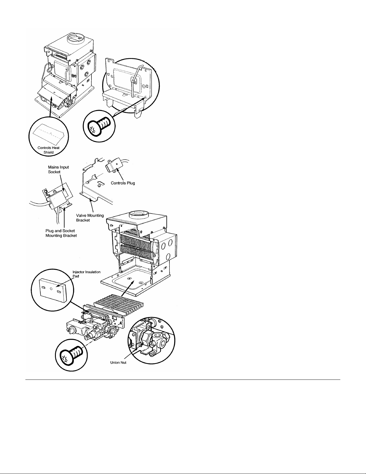
ANNUAL SERVICING - Page 26
Manual Controls Models
Remove the thermostat phial from the heat exchanger and
carefully remove the capillary from its routing clips.
Remove the controls heat shield from its retaining
Remove the four screws retaining the combustion box door
and remove the door.
Lift and remove the injector insulation pad.
Slacken the screw securing the plug and socket mounting
bracket to the valve mounting bracket.
Pull the mounting bracket to the left and disconnect the
controls plug.
Lay the mounting bracket and cable to one side.
Disconnect the union nut from the gas service tap.
Slacken the two screws securing the controls to the base
tray and remove the screws securing the controls to the
combustion box.
Withdraw the controls assembly from the combustion box.
Page 27
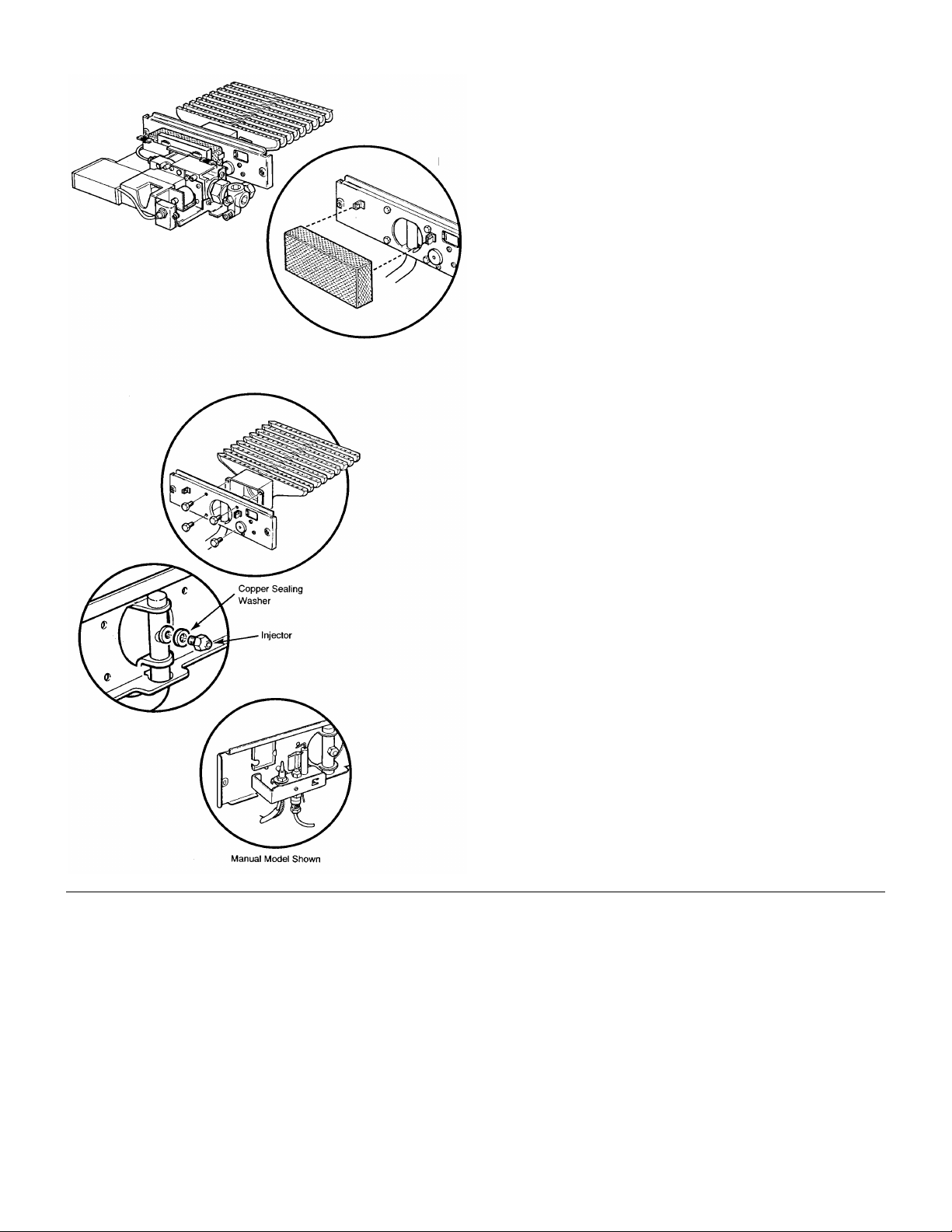
ANNUAL SERVICING - Page 27
Cleaning the Lint Arrestor
Remove the lint arrestor from the controls and clean away
any deposits.
Cleaning the Burner and Main Injector
Remove the four hexagon headed screws holding the burner
to the burner mounting plate.
Carefully clean any deposits from the burner blades
and venturi inlet.
Remove the injector from the feed pipe, retaining the copper
sealing washer. Clean the injector and reassemble in
reverse order.
Cleaning the Pilot / A.S.D. Assembly
Note:- No attempt should be made to clean the device
using any hard tools, including pins or wire.
The thermocouple, electrode and pilot burner that make
up the pilot assembly are not replaceable as separate
items. If any part is damaged then the pilot assembly
should be replaced.
During annual appliance servicing the pilot assembly should
be inspected for damage to any of the component parts and
any lint or debris should be carefully removed from the
aeration hole.
Check that the spark gap between the electrode and the pilot
burner is between 2.5 and 4mm.
Reassemble the burner in reverse order and refit the
lint arrestor and injector insulation pad.
Page 28
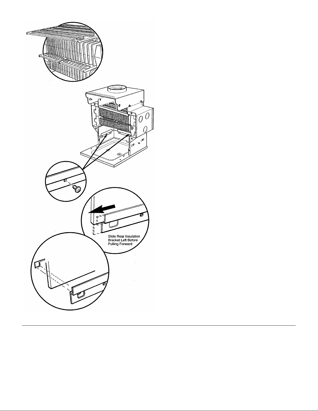
ANNUAL SERVICING - Page 28
Cleaning the Heat Exchanger
Remove the top baffle and the central baffles from the heat
exchanger.
Remove the side and rear insulation pieces by undoing the
screws retaining the support brackets and sliding the rear
bracket to the left and both side brackets forward.
Each bracket may then be removed along with the
insulation.
Clean between the heat exchanger fins and flueways with
suitable brushes and remove any deposits from the
combustion box base tray.
Clean away any lint or other deposits from the boiler hood
and builders opening.
Reassemble the insulation in reverse order and refit the
baffles.
Reassemble the appliance in reverse order, re-commission
the appliance and check for gas soundness.
Complete the relevant section of the “Benchmark”
Installation, Commissioning and Service Record Log
Book and hand it back to the user.
Page 29
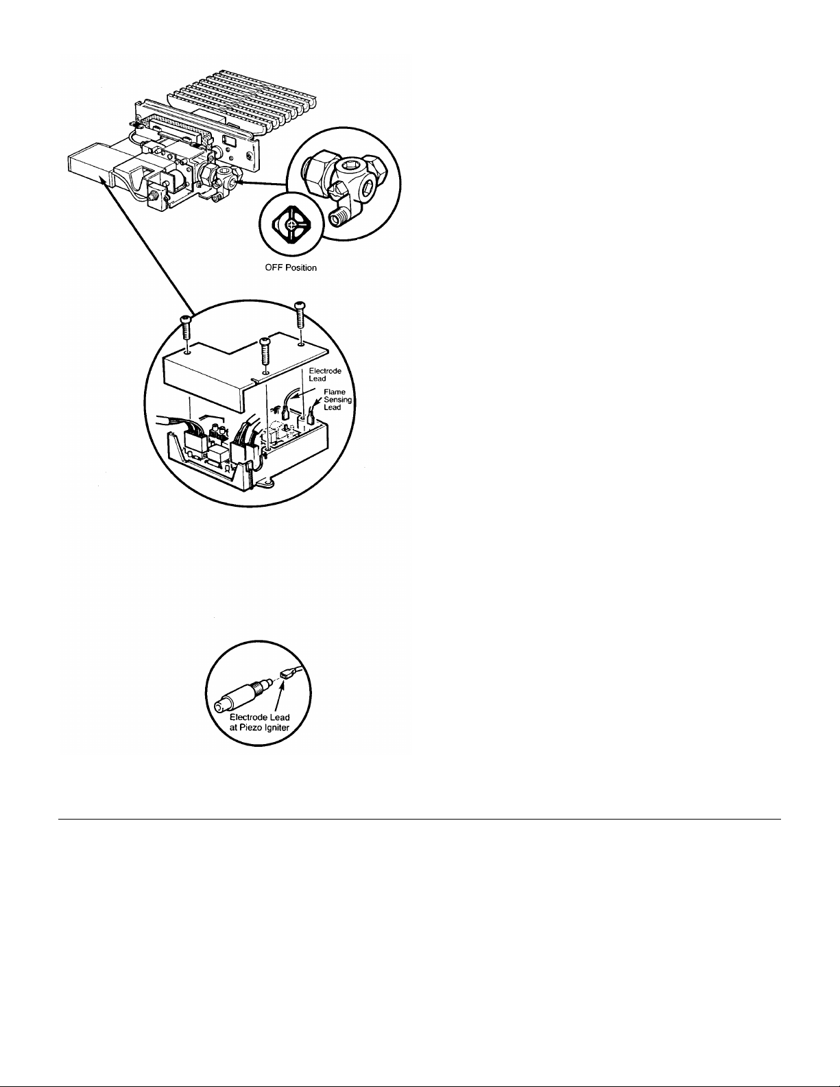
CHANGING COMPONENTS - Page 29
To change any components on the back boiler it is
necessary to remove the fire front.
After changing any components carry out gas
soundness checks.
Removal of Firefront
Isolate the electrical supply to the appliance and ensure the
permanent live (when fitted) has also been isolated.
Turn the gas service tap to the OFF position.
Refer to the separate firefront instructions for the removal of
the firefront.
Remove the controls assembly from the boiler as described
under “Annual Servicing’.
Flame Sensing Lead
ELECTRONIC CONTROL MODELS
Remove the three screws holding the controls box cover on
and remove the electrode lead from its terminal on the PCB
and the sensing probe. The lead has a white sleeve at the
probe end.
Reassemble in reverse order.
Ignition Lead
ELECTRONIC CONTROL MODELS
Remove the three screws holding the controls box cover on
and remove the electrode lead from its terminal on the PCB
and the electrode. The lead has a black sleeve at the
electrode end.
Reassemble in reverse order.
MANUAL CONTROL MODELS
Remove the controls heat shield from its clips if not already
done so.
Pull the lead off the spade terminals on the piezo unit
and the ASD electrode.
Reassemble in reverse order.
Page 30
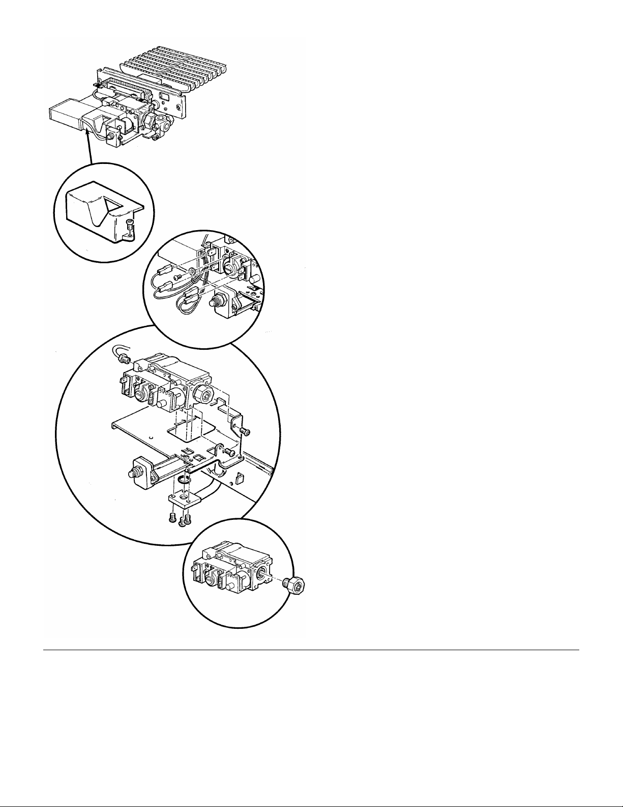
CHANGING COMPONENTS - Page 30
Gas Valve
ELECTRONIC CONTROL MODELS
Remove the screw holding the valve cover to the controls
mounting bracket and remove the cover.
Disconnect the electrical connections from the valve, noting
the position of each wire.
Remove the two screws holding the valve to the controls
mounting bracket adjacent to the union nut and tailpiece.
Undo the pilot feed pipe nut from the valve.
Remove the three screws holding the burner feed pipe to the
valve, being careful not to lose or damage the “O” ring seal.
Remove the valve from the controls mounting bracket.
Remove the tailpiece and union nut from the original valve
and fit to the new one.
Reassemble in reverse order.
Page 31
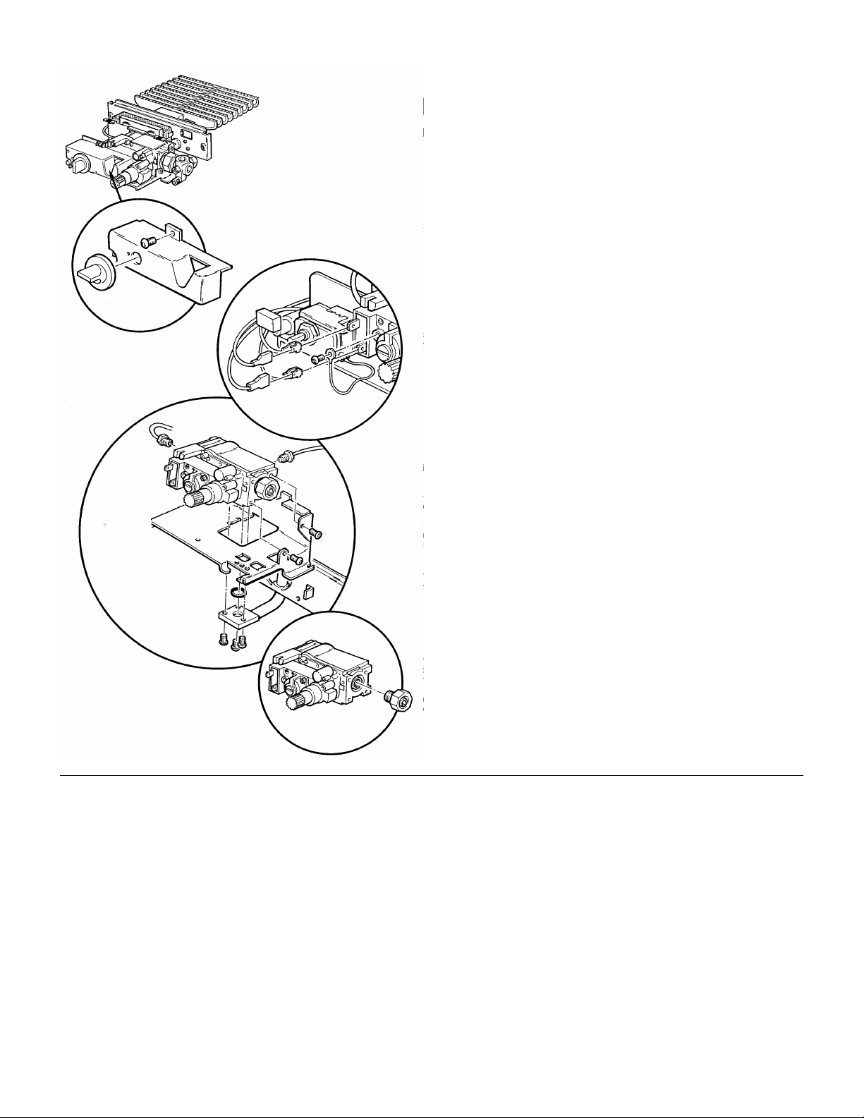
CHANGING COMPONENTS - Page 31
MANUAL CONTROL MODELS
Remove the control knob.
Remove the screw holding the valve cover to the controls
mounting bracket and remove the cover.
Disconnect the electrical connections from the valve.
Remove the two screws holding the valve to the controls
mounting bracket adjacent to the union nut and tailpiece.
Undo the pilot feed pipe nut and thermocouple from the
valve.
Remove the three screws holding the burner feed pipe to the
gas valve, being careful not to lose the “O” ring seal.
Remove the valve from the controls mounting bracket.
Remove the tailpiece and union nut from the original valve
and fit to the new one.
Reassemble in reverse order.
Page 32
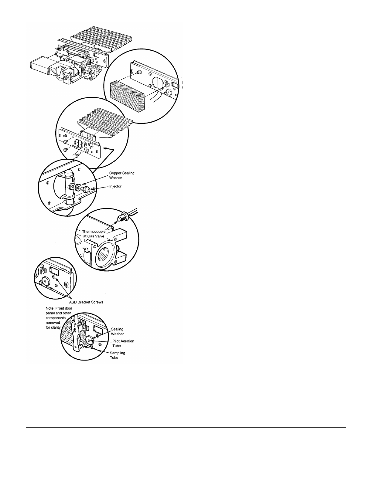
CHANGING COMPONENTS - Page 32
Burner and Main Injector
Remove the lint arrestor.
Remove the four hexagon headed screws holding the burner
to the mounting plate.
If required the main injector can be unscrewed from the feed
pipe and replaced. The copper sealing washer must be
retained for re-use.
Reassemble in reverse order.
Pilot / A.S.D. Assembly
WARNING: The pilot I A.S.D. assembly should not be
adjusted in any way.
The A.S.D. must not be altered so that it will not operate
or be bypassed in anyway.
The thermocouple cannot be changed as an individual
component. The complete assembly must be replaced
in the event of one or other component failure(s). Only
use a Genuine Baxi Spare Part.
Remove the controls heat shield from its clips if not already
done so.
Remove the ASD thermocouple nut at the rear of the valve.
Remove the ignition lead from the ASD electrode (and flame
sensing lead on electronic models). Undo the pilot feed pipe
at the ASD.
Remove the three screws holding the burner feed pipe
flange to the underside of the valve.
Separate the valve and burner assemblies.
Remove the lint arrestor.
Undo the two screws holding the ASD bracket to the burner
mounting plate.
Remove the original sealing washer from the burner
mounting plate.
Undo the screw holding the ASD to its bracket.
Fit the new ASD to the bracket. When fitting the ASD ensure
that the pilot aeration tube engages in its hole in the burner
mounting plate.
Ensure that the mounting plate is clean and then peel the
adhesive backing paper off the new sealing washer.
Align the hole in the new washer with the pilot aeration tube
protruding through the mounting plate.
Reassemble in reverse order.
Page 33
CHANGING COMPONENTS - Page 33
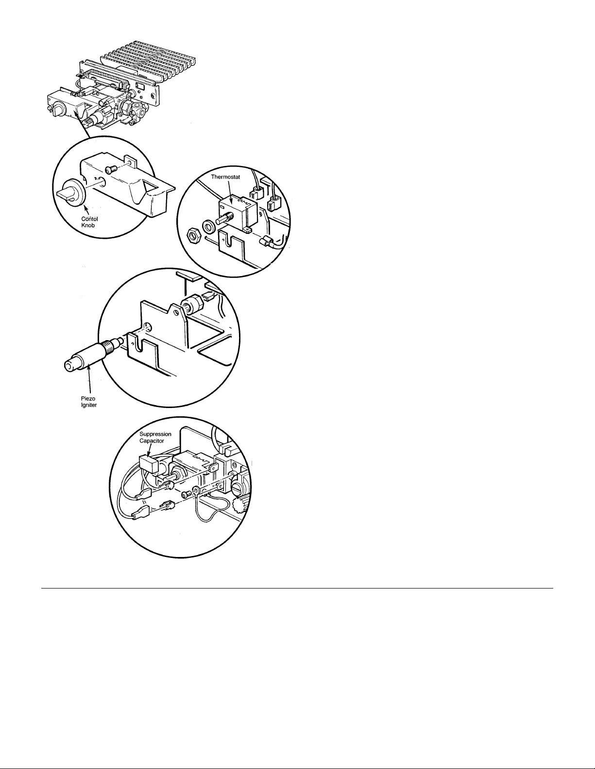
Thermostat
MANUAL CONTROLS ONLY
Remove the control knob. Undo the screw retaining the
valve cover and remove the cover.
Undo the locknut retaining the thermostat to the controls
mounting bracket. Ease the thermostat away from the
bracket and disconnect the electrical connections noting
their positions.
Reassemble in reverse order.
Piezo Igniter Unit
MANUAL CONTROLS ONLY
Remove the controls heat shield from its retaining clips if not
already done so.
Remove the control knob. Undo the screw retaining
the valve cover and remove the cover.
Pull the igniter lead off the piezo and undo the
plastic locknut. Remove the piezo igniter unit.
Reassemble in reverse order.
Suppression Capacitor
MANUAL CONTROLS ONLY
The controls may remain in situ but the controls heat shield
must be removed from its retaining clips.
Remove the control knob. Undo the screw retaining the
valve cover and remove the cover.
Note the positions of the electrical connections on the valve
and remove them.
Remove the capacitor connections from the
valve
Reassemble in reverse order.
Page 34
CHANGING COMPONENTS - Page 34
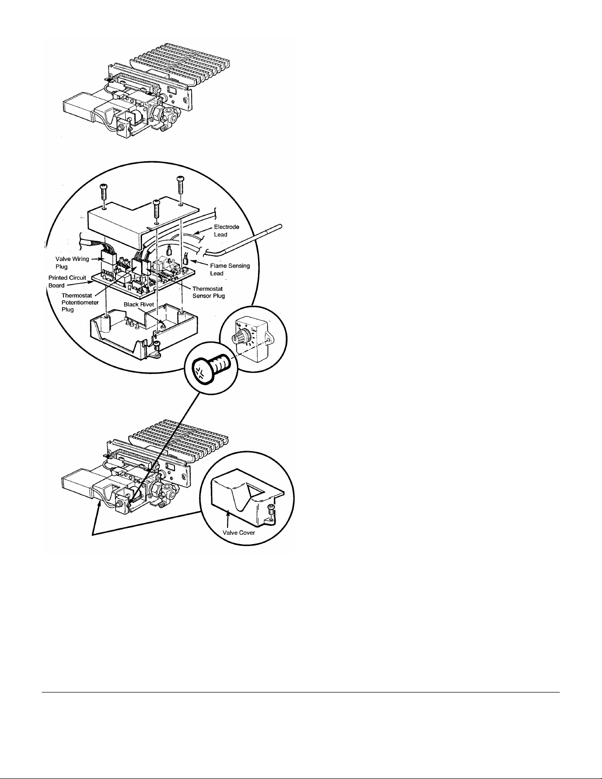
Thermostat Sensor
ELECTRONIC CONTROLS ONLY
Undo the three screws retaining the control box cover and
remove the cover.
Disconnect the thermostat sensor plug from the PCB.
Thermostat Potentiometer
ELECTRONIC CONTROLS ONLY
Remove the controls heat shield from its retaining clips if not
already done so.
Undo the three screws retaining the control box
cover and remove the cover.
Disconnect the thermostat potentiometer plug from the PCB
and remove the potentiometer wires from their guide slot in
the control box side.
Undo the screw holding the thermostat potentiometer to the
controls mounting bracket and remove the potentiometer by
disengaging its locating tab.
Reassemble in reverse order.
Printed Circuit Board
ELECTRONIC CONTROLS ONLY
Remove the controls heat shield from its retaining clips if not
already done so.
Undo the three screws retaining the control box cover and
remove the cover.
Disconnect the three multi-pin plugs, flame sensing lead and
ignition lead from the PCB, noting their
positions.
Undo the screw retaining the valve cover and remove the
cover.
Pull the valve wiring grommet out of the slot in the control
box.
Disconnect the lead from the upper solenoid connection.
Undo the screw retaining the control box and remove the
box.
Push out the black rivet retaining the PCB.
Fit the new PCB using the rivet.
Reassemble in reverse order.
Page 35
SHORT PARTS LIST - Page 35
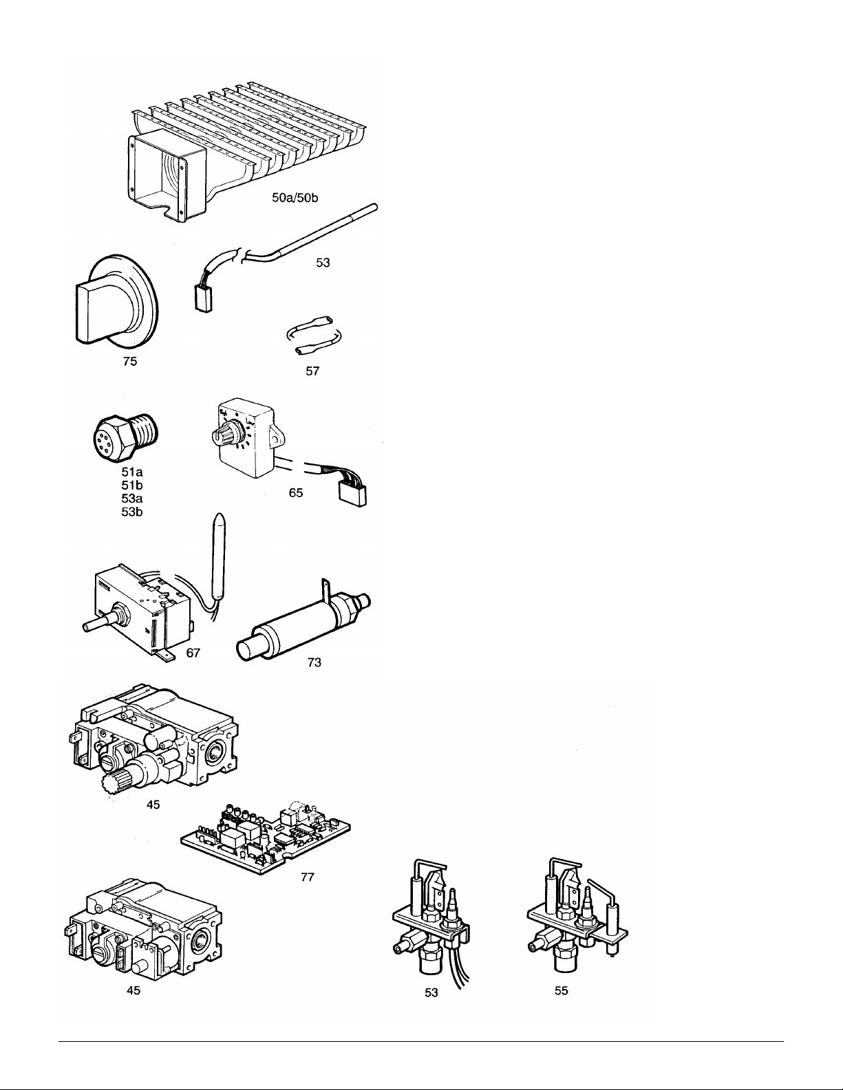
Key
No.
73
50b
50a
51a
35a
51b
53b
45
45
65
53
77
53
55
67
75
57
57
G.C.
No.
183 936
E01-683
E01-682
378 845
378 845
378 846
378 846
193 128
193 128
378 847
378 844
E00-118
E00-132
E00-133
378 862
364 685
E00-121
E00-122
Description
Igniter Piezo (M models)
Burner - Large
Aeromatic AC02/011452
Burner Small
Aeromatic AC02/01 1453
Injector Burner 45/4 M
Stereomatic B20
Injector Burner 45/4 E
Stereomatic B20
Injector Burner 57/4
Stereomatic B21
Injector Burner 57/4
Stereomatic B21
Gas Valve - Manual
Gas valve - Electronic
Potentiometer & Leads (E models)
Sensor Thermostat (E models)
Printed Circuit Board (E models)
Pilot / A.S.D. Assembly (M models)
Pilot / A.S.D. Assembly (E models)
Thermostat -Boiler (M models)
Knob - Thermostat Boiler (M models)
Lead-Electrode
Lead-Sensing (E models)
Manufacturers
Part No.
040456
239376
239355
234511
234511
234512
234512
236129
236579
232219
232215
237730
240117
238292
233952
226821
237811
237812
Page 36
FAULT FINDING 57/4M & 45/4M - Page 36
Page 37
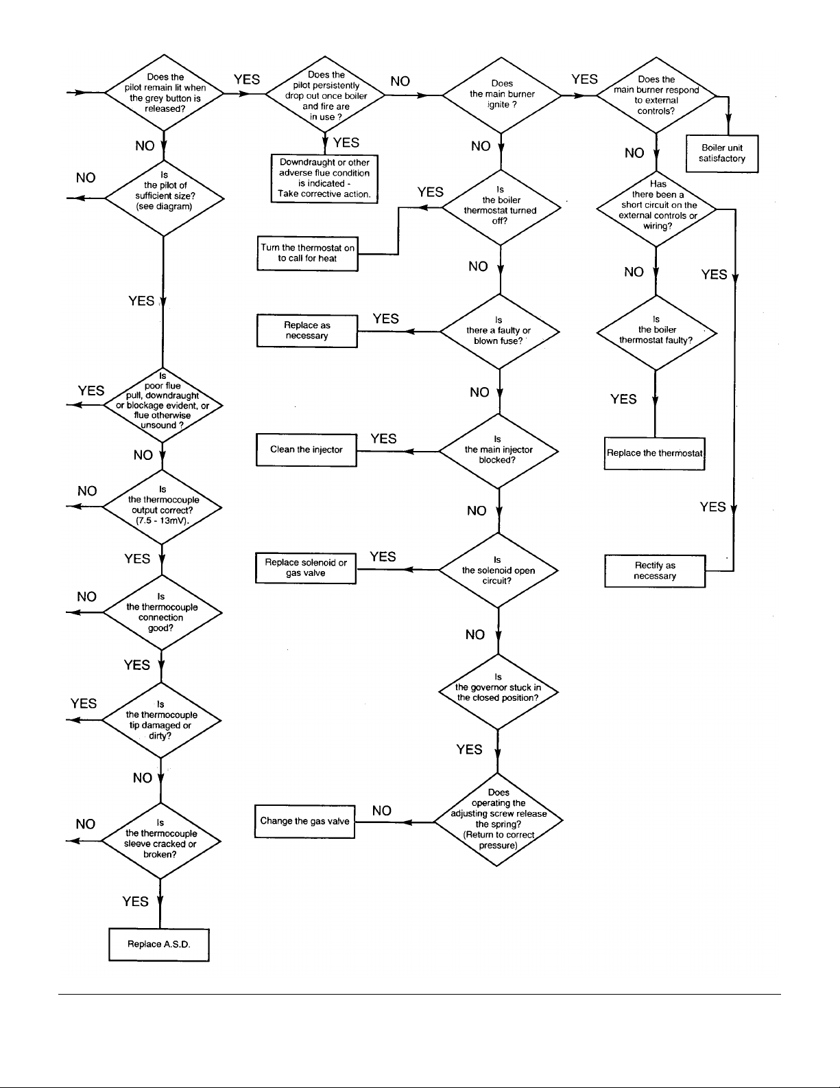
FAULT FINDING 57/4M & 45/4M - Page 37
Page 38
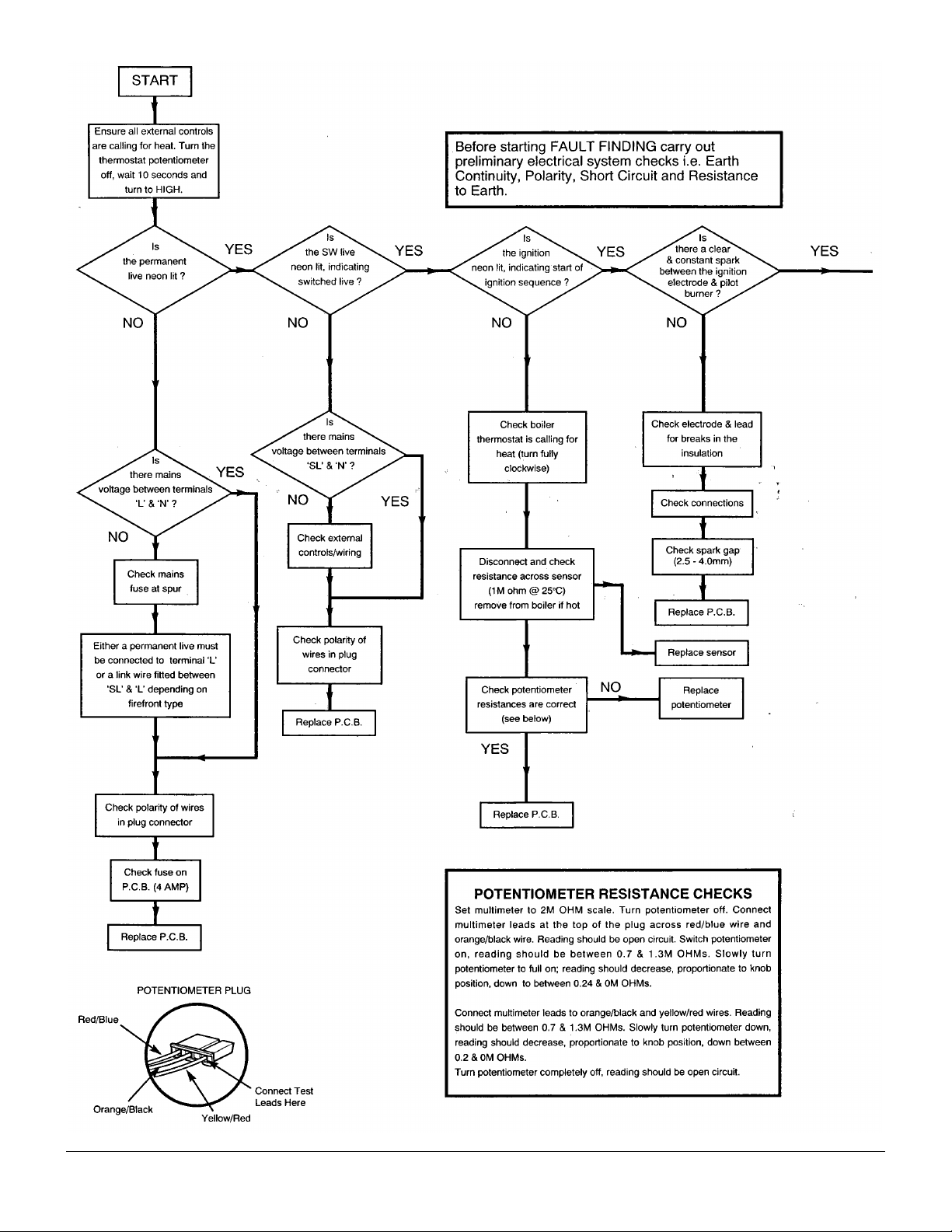
FAULT FINDING 57/4E & 45/4E - Page 38
Page 39
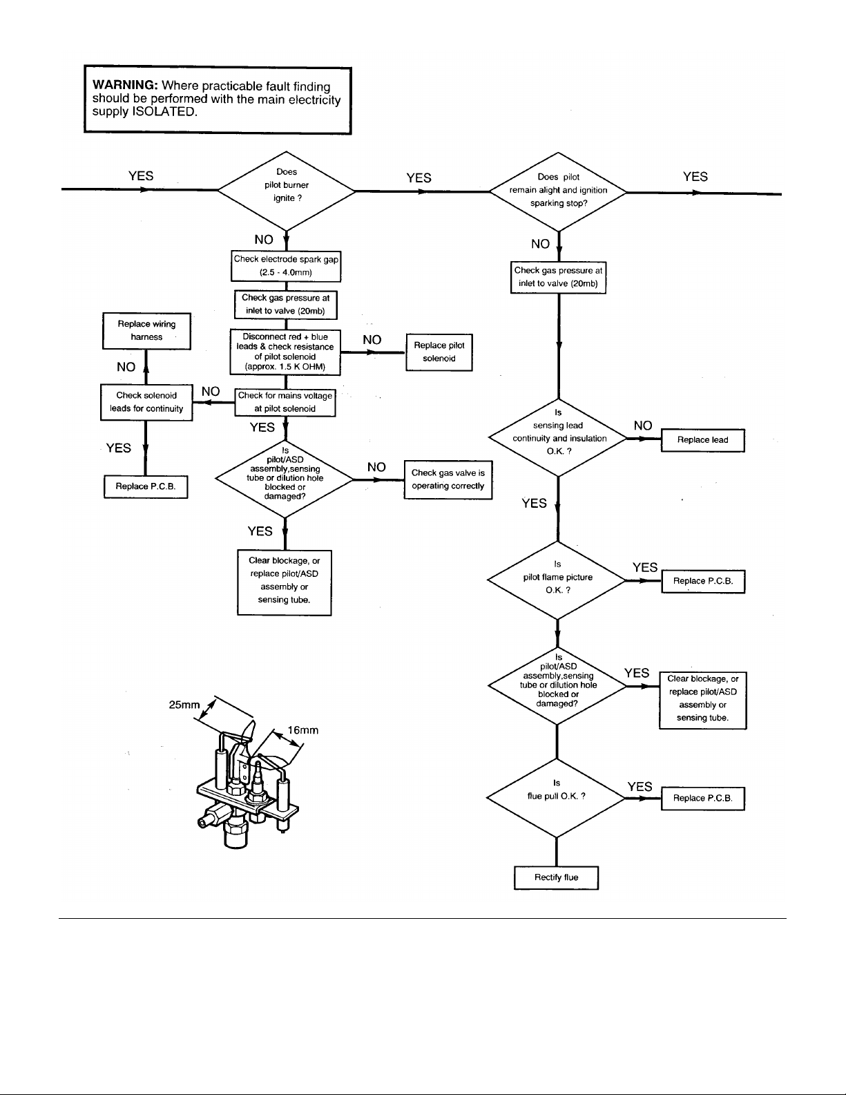
FAULT FINDING 57/4E&45/4E - Page 39
Page 40
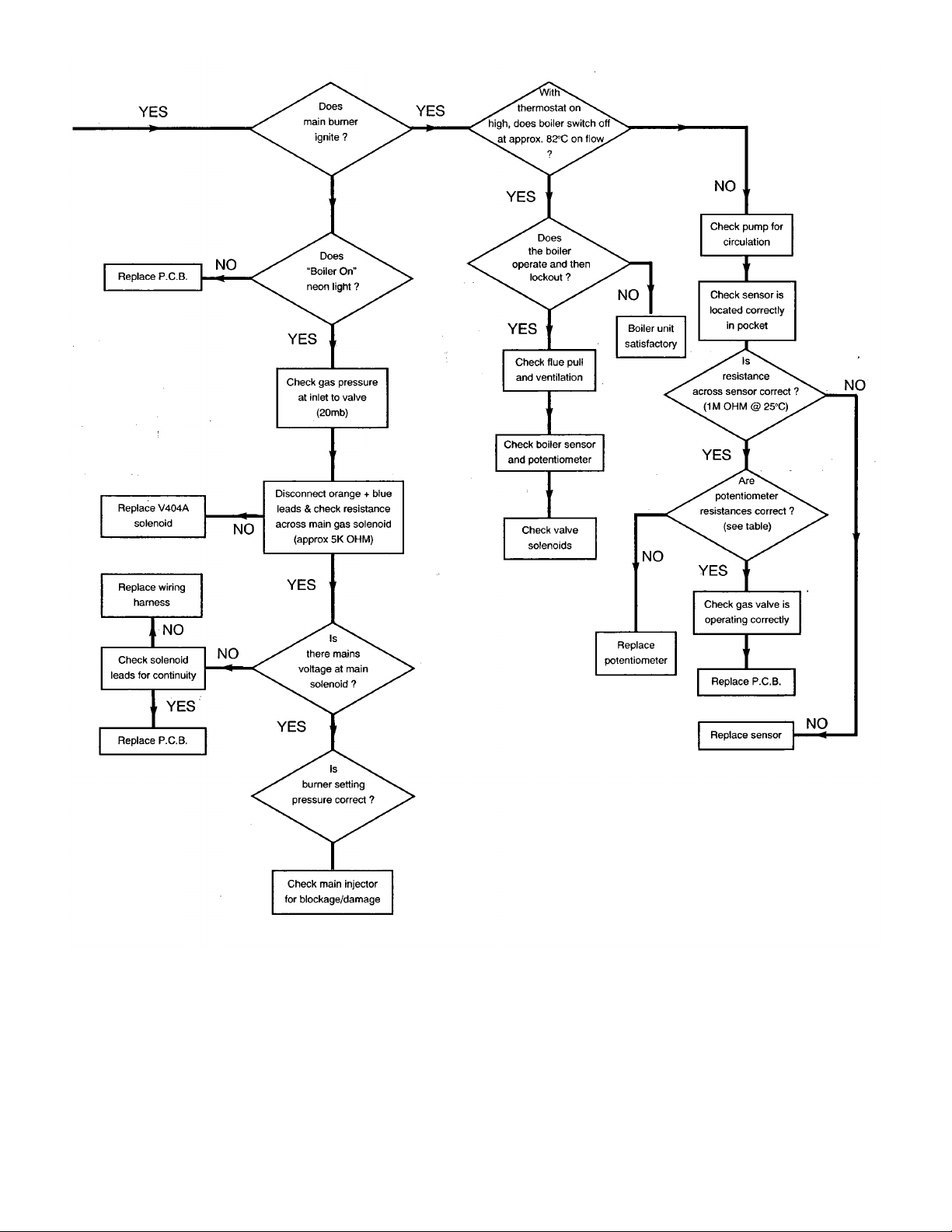
FAULT FINDING 57/4E&45/4E - Page 40
Click here for Helplines
 Loading...