

Page 1

Supplied By www.heating spares.co Tel. 0161 620 6677
Please leave these instructions with the user
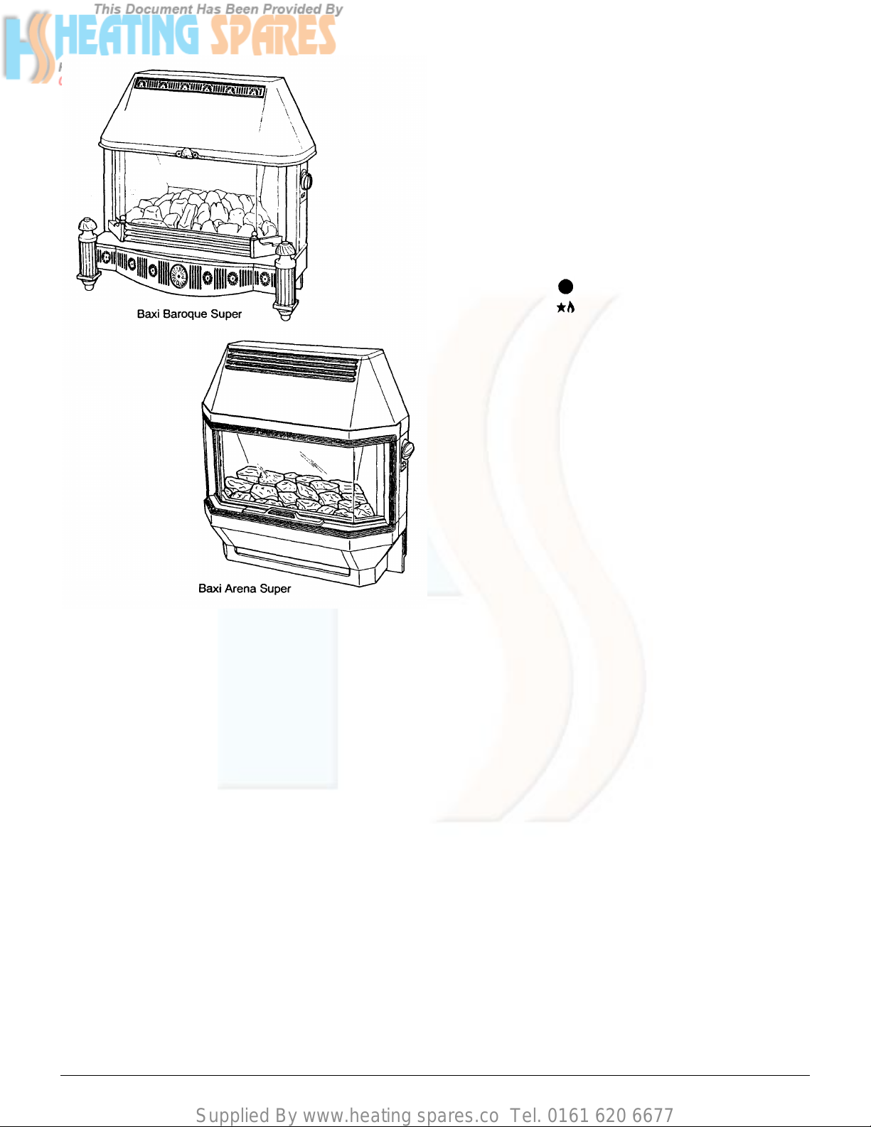
Baxi Arena Super
Baxi Baroque Super
Living Flame Effect Gas Fires
Natural Gas
Comp N° 235317 - Issue 8 - 11/99
Installation and
Servicing Instructions
Baxi Arena Super - G.C.N° 32 077 34
Baxi Baroque Super - G.C.N° 32 077 35
Page 2

Supplied By www.heating spares.co Tel. 0161 620 6677
Contents - Page 2
Introduction
PAGE 3
Technical Data
Site Requirements
Installation
Commissioning the Fire
Fitting the Outer Case
Annual Servicing
PAGE 4
PAGE 5-6
Fireplace Opening
Hearth Mounting
Wall Fixing
Existing Chimneys
Pre-Cast Flues
Gas Supply
Electrical Supply
PAGE 7-9
Initial Preparation
Fitting the Fire
Electrical Connections
PAGE 10-12
Spillage Detection
PAGE 13-14
Baxi Baroque
Baxi Arena
PAGE 15-19
Cleaning the Pilot Assembly
Cleaning the Burner/Injectors
Changing Components
Fault Finding
Short Parts List
PAGE 20-27
Glass Frame
Frame Sealing Rope
Coal Bed
Burners and Injectors
Light Switch
Electrode Lead
Spark Generator
Resistor
Pilot Assembly
Electro-Magnetic Unit
Control Tap and Micro-switch
PAGE 28-29
PAGE 30
Page 3
Supplied By www.heating spares.co Tel. 0161 620 6677
INTRODUCTION - Page 3
Description
The Baxi Baroque Super and Baxi Arena Super are living
flame effect gas fires with a heat input of 5.57 kW (19,000
Btu/h) and an output of 3.40 kW (11,590 Btu/h) at its
maximum setting. The fires are available for use with Gas
Type G20 (Natural Gas) at 20mbar supply pressure. The
fires are suitable for either hearth or wall mounting and are
designed to be used on NATURAL GAS ONLY. NOTE: The
data and spillage test labels are located on the inner fire
support feet behind the fender front.
Electronic ignition is provided to light the pilot. The fire is
controlled by a control knob positioned on the right hand side
of the case. This control knob has six positions giving a
choice of four output settings.
Position - OFF
Position - PILOT
Position 1 - LOW
Position 2 - MEDIUM
Position 3 - MEDIUM/HIGH
Position 4 - HIGH
The artificial coal bed may be illuminated by concealed bulbs
as and when required. The light effect is operated by a
switch situated below the control knob. It may be used
whether the fire is ON or OFF.
NOTICE
DISCOLOURATION OF WALL SURFACES
Most heating appliances generate warm air convection
currents and transfer heat to any wall surface against
which they are situated.
Some soft furnishings (such as blown vinyl wallpapers)
may not be suitable for use where they are subject to
temperatures above normal room levels and the
manufacturer’s advice should be sought before using
this type of wall covering adjacent to any heating
appliance.
The likelihood of wall staining from convected air
currents will be increased in environments where high
levels of cigarette smoke or other contaminants exist.
WARNING
The addition of anything that may interfere with the
normal operation of the appliance (e.g. FLUE DAMPERS,
ECONOMISERS etc.) without the express written
permission of BAXI LIMITED could invalidate the
appliance warranty and infringe the GAS SAFETY
(Installation and Use) REGULATIONS.
The fire is manufactured to British Standards 5258 Part 5
and 6332 Part 2.
Installation
The installation must be carried out by a CORGI Registered
Installer or other competent person and be in accordance
with the relevant requirements of the GAS SAFETY
(Installation and Use) REGULATIONS, the BUILDING
REGULATIONS (Scotland) (Consolidation), the LOCAL
BUILDING REGULATIONS and the CURRENT I.E.E.
WIRING REGULATIONS. It should also be in accordance
with the relevant BRITISH STANDARD CODES OF
PRACTICE.
Important Information
This product contains Refractory Ceramic Fibres (R.C.F.)
which are man-made vitreous silicate fibres. Excessive
exposure to these materials may cause temporary irritation
to eyes, skin and respiratory tract. Care must be taken when
handling these articles to ensure the release of dust or fibres
is kept to a minimum.
To ensure that the release of fibres from these articles is
kept to a minimum, during installation and servicing it is
recommended that a H.E.P.A. filtered vacuum is used to
remove any dust, soot or other debris accumulated in and
around the appliance. This should be performed before and
after working on the installation.
It is recommended that any replaced item(s) are not broken
up but sealed within heavy duty polythene bags and clearly
labelled “R.C.F. waste”. This is not classified as “hazardous
waste” and may be disposed of at a tipping site licensed for
the disposal of industrial waste.
Protective clothing is not required when handling these
articles but it is recommended that gloves are worn and the
normal hygiene rules of not smoking, eating or drinking in
the work area are followed and always wash hands before
eating or drinking.
Page 4
Supplied By www.heating spares.co Tel. 0161 620 6677
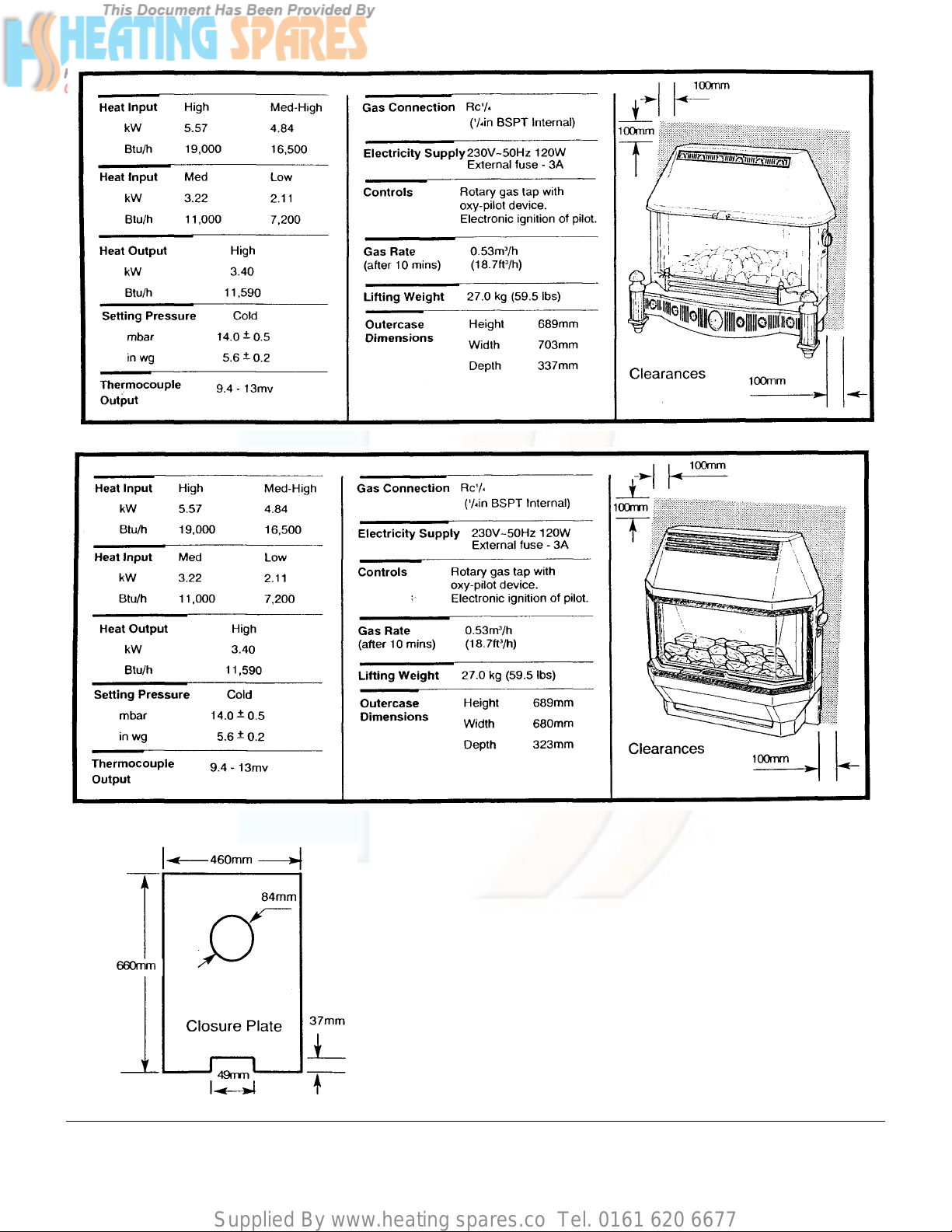
TECHNICAL DATA - Page 4
Baxi Baroque Super
Baxi Arena Super
B.S. Codes of Practice
STANDARD
B.S. 6891
B.S. 5871
B.S. 5440: Part 1
B.S. 5440: Part 2
SCOPE
Gas Installation
Installation of gas fires, convectors and
fire/back boilers.
Flues.
Air Supply
Page 5
Supplied By www.heating spares.co Tel. 0161 620 6677
SITE REQUIREMENTS - Page 5
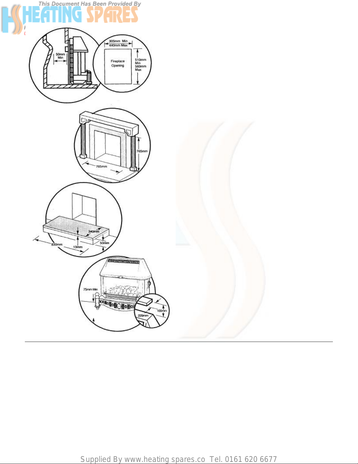
Fireplace Opening
The installation requires a fireplace opening as illustrated. At
the height of the flue spigot the opening shall be no less than
100mm (4in) deep, measured from the front face of the
opening to the fireplace back brick. There must be a
minimum of 412mm (167/32in) between the base of the
fireplace opening and the bottom of the flue spigot.
NOTE: Where possible the fireplace opening should be
to the minimum dimensions, particularly for wall
mounted installations.
The fireplace must be built from non-combustible materials
and have a flat vertical surface measuring 765mm (301/8in)
wide x 765mm (301/8in) high around the fireplace opening. If
a fire surround is to be used then its rear section must meet
the same requirements.
Any gaps between the wall and the surround must be
sealed.
HEARTH MOUNTING
If the fire unit is to be hearth mounted then the hearth must
be of a non-combustible material at least 13mm (½in) thick,
measuring at least 340mm (133/8in) deep by 830mm (32¾in)
wide. It must be fitted central to the fireplace opening. The
top surface of the hearth should be a minimum of 50mm
(2in) above floor level.
On no account should the fire be fitted directly onto a
combustible floor or carpet.
WALL FIXING
If the fire is to be wall mounted, then the wall must be noncombustible and the base of the fire must be no less than
75mm (3m) above floor level.
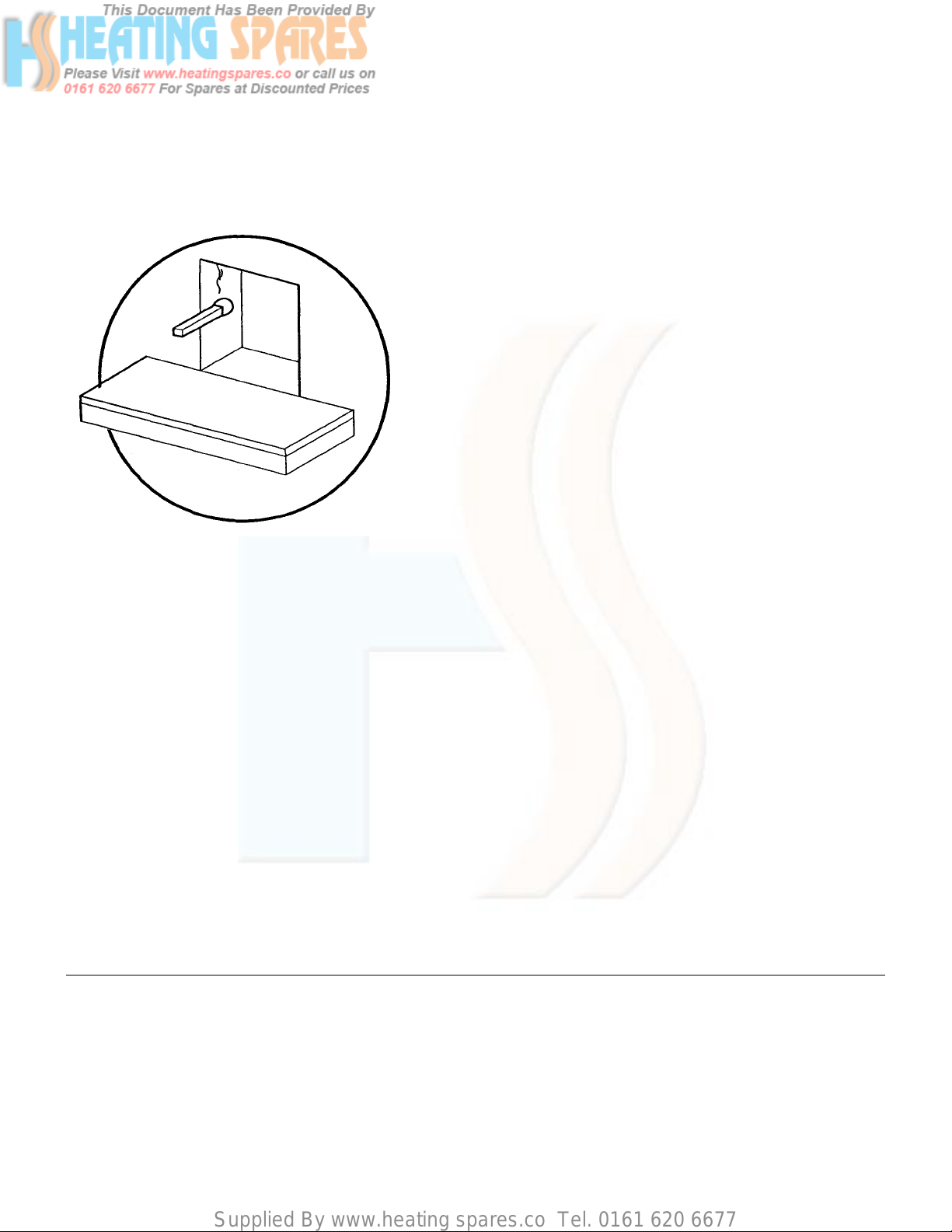
A shelf may be fitted above the fire, provided that it is at
least 100mm (4in) above the fire canopy and not more than
229mm (9in) in depth.
Page 6
Supplied By www.heating spares.co Tel. 0161 620 6677
Site Requirements - Page 6
Existing Chimneys
A chimney which has previously been used to burn solid fuel
MUST be swept before beginning the installation and any
restrictions such as dampers or register plates must be
removed. The chimney must be at least 3.10m (10ft) in
height and also meet the following requirements:
1) It must not be cracked.
2) It must serve one room only.
3) It must not be joined with any void, space or any
room other than that in which the fire is fitted.
4) It must not be blocked by paper or rubble etc.
5) It must have a positive flue pull up the chimney.
6) It must have a standard 229mm x 229mm (9in x
9in) section or a 127mm(5in) flue liner.
If there is no positive airflow up the chimney DO NOT FIT
THE FIRE. Seek expert advice before continuing with the
installation. A positive flue pull can be detected by holding a
lighted match or taper near to the fireplace opening.
PRE-CAST FLUES
The fire is suitable for fitting into properly designed and
constructed pre-cast flues, complying with BS 1289. The flue
must be at least 3.10m (10ft) in height and have a flue way
of at least 197mm x 67mm (7¾in x 25/8in) or equivalent
cross-sectional area.
NOTE: It is important to ensure that the mortar between
the blocks has not been forced into the flue way. If there
is mortar in the flue way, then it must be removed. If
raking blocks are used, they must be fitted according to
the manufacturer’s instructions.
Gas Supply
The gas installation should be in accordance with BS 6891.
The connection to the appliance is Rc¼ (¼in BSPT internal)
and is located at the centre (rear) of the fire, permanently
fixed to the bottom of the back plate. Ensure that the
pipework from the meter to the appliance is of adequate
size. Do not use pipes of a smaller diameter than the
appliance gas connection.
Electrical Supply
THIS APPLIANCE MUST BE EARTHED The mains supply
required is 230V ~ 50Hz fused at 3A.
NOTE: The method of connection to the electricity
supply must facilitate complete electrical isolation of the
appliance, preferably by the use of a fused three pin
plug and unswitched shuttered socket outlet, both
complying with the requirements of BS 1363.
Alternatively, connection may be made via a fused
double-pole isolator with a contact separation of at least
3mm (1/8in) in all poles and serving the appliance only.
Page 7

Supplied By www.heating spares.co Tel. 0161 620 6677
INSTALLATION - Page 7
Initial Preparation
To unpack the fire, remove the packing piece complete with
fitments and the pack containing the canopy and hearth
assembly. Place to one side. Remove the plastic bag and
remaining packing piece. Lift the fire from its carton.
Fitting the Fire
HEARTH MOUNTING
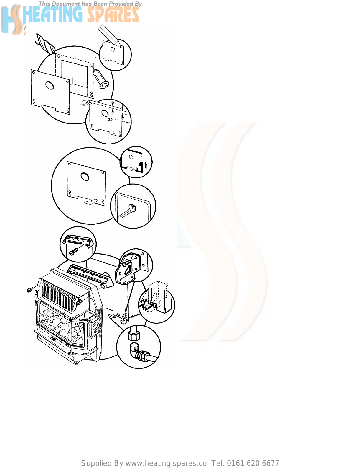
Take the closure plate provided and hold centrally across the
fireplace opening with the bottom edge resting on the hearth.
NOTE: Where the closure plate is more than adequate
to cover the fireplace opening and to prevent the sealing
tape from becoming visible, it is advisable to trim the
closure plate as follows:
Cut 32mm (1¼in) off the top of the closure plate (i.e.
through the centre line of the top two fixing holes) and
then trim the top corners at an angle of 45° to a depth of
25mm (1in). If necessary, cut a hole in the closure plate
for the gas supply pipe.
Seal all edges of the closure plate with a suitable tape. DO
NOT COVER THE AIR RELIEF OPENING IN ANY WAY. If
the closure plate has been cut for the gas supply pipe, seal
around this opening too.
Hold a lighted taper or match to the spigot hole in the closure
plate. If the flame is pulled into the opening, proceed with the
installation. If the flame is NOT pulled into the opening, preheat the chimney for a few minutes then re-check for flue
pull. If there is still no definite flow into the spigot opening,
the chimney may need attention. DO NOT CONTINUE WITH
THE INSTALLATION - SEEK EXPERT ASSISTANCE.
Take the backing plate from the fittings pack and secure to
the fire using the two N° 8 x 5/8in self tapping screws
provided.
Locate the flue spigot in the hole in the closure plate and
push the fire backwards as far as possible.
NOTE: A flue spigot extension may be used with this
appliance, but must not exceed 150mm (6in) when
measured from the back of the fire.
Level the fire by adjusting the front feet.
Make the gas connection to the union elbow and tighten the
flared joint.
Page 8
Supplied By www.heating spares.co Tel. 0161 620 6677
INSTALLATION - Page 8
Wall Fixing
Using the closure plate supplied as a template, hold it
centrally across the fireplace opening with the bottom edge
level with the base of the fireplace opening. Mark out the six
hole positions. Remove the closure plate and drill the fixing
holes using a 6mm drill to accept the wall plugs provided.
NOTE: Where the closure plate is more than adequate
to cover the fireplace opening and to prevent the sealing
tape from becoming visible, it is advisable to trim the
closure plate (after marking the fixing holes) as follows:Cut 32mm (1¼in) off the top of the closure plate (i.e.
through the centre line of the top two fixing holes) and
then trim the top corners at an angle of 45° to a depth of
25mm (1in). If necessary, cut a hole in the closure plate
for the gas supply pipe.
Replace the closure plate, making sure to line it up with the
holes previously drilled and plugged and seal all edges with
a suitable tape. DO NOT COVER THE AIR RELIEF
OPENING IN ANY WAY.
If the closure plate has been cut for the gas supply pipe, seal
around this opening too.
Hold a lighted taper or match to the spigot hole in the closure
plate. If the flame is pulled into the opening, proceed with the
installation. If the flame is NOT pulled into the opening, preheat the chimney for a few minutes then re-check for flue
pull. If there is no definite flow into the spigot opening, the
chimney may need attention.
DO NOT CONTINUE WITH THE INSTALLATION -SEEK
EXPERT ASSISTANCE.
Take the backing plate from the fittings pack and fix it to the
wall as shown using the 1½in wood screws provided.
Fix the two wall mounting brackets in position using the four
1½in wood screws provided.
Take the fire, two N° 8 x 5/8in self tapping screws,
screwdriver and locate the flue spigot in the hole in the
closure plate, push the fire backwards as far as possible,
ensuring that the rear feet locate positively on the wall
mounting brackets. Whilst holding the fire in position, secure
the fire to the backing plate with the screws.
Fix the fire firmly to the wall mounting brackets as shown
using the two N° 8 x 5/8in self tapping screws provided.
Make the gas connection to the union elbow and tighten the
flared joint.
Page 9
Supplied By www.heating spares.co Tel. 0161 620 6677
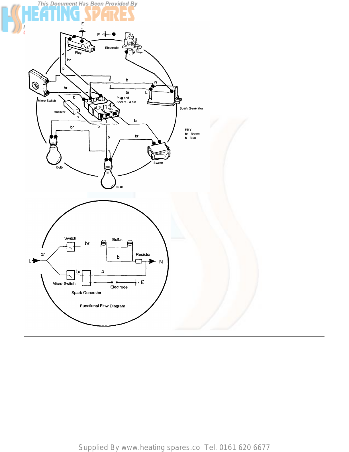
Electrical Connections - Page 9
Electricity is supplied to the fire unit via
the plug-and-cable assembly provided
with the appliance.
WARNING
THIS APPLIANCE MUST BE EARTHED.
3 core input cable for connection to the
mains input must NOT be less than
0.5mm2 (16 x 0.2mm) PVC heat resistant
to 70°C grade 1 to BS 6500 table 15 or
16.
Page 10

Supplied By www.heating spares.co Tel. 0161 620 6677
COMMISSIONING THE FIRE - Page 10
Purge any air from the gas inlet and make good the gas
connection. Switch on the gas. Check for gas soundness.
Remove the glass frame by disengaging the retaining
clamps and lifting away. Remove the polystyrene packing
piece securing the coal bed in position.
Remove the coal bed from its plastic bag and carefully
replace in position on the burner.
CAUTION: The coal bed is extremely fragile and must
be handled accordingly. Gloves should be worn and any
inhalation of the dust should be avoided. Keep the coals
away from children at all times. Please read the
Important Information section on page 3.
Remove any labels fixed to the glass frame assembly
and clean both sides of the glass panels before
replacing the glass frame.
Replace the glass frame and lock in place by engaging the
retaining clamps.
Take the lead provided and fit the plug into the socket on the
fire. Connect to the electricity supply, taking care to route the
cable so that it will not come into contact with any hot
surface.
Page 11

Supplied By www.heating spares.co Tel. 0161 620 6677
COMMISSIONING THE FIRE - Page 11
Check the electricity supply to the fire unit by switching on
the illumination bulbs to the coal bed. If the bulbs light,
switch off and continue with commissioning the fire. If the
bulbs do not light, isolate the electricity supply and perform
preliminary electrical system checks before proceeding i.e.
earth continuity, polarity, resistance to earth etc.
Isolate the electricity supply.
Remove the electrical cover on the right hand side of the
chassis as shown, by removing the fixing screw.
Release the pressure test point sealing screw and connect a
pressure gauge in position.
Reconnect the electricity supply.
Push in the control knob, turn to the IGNITION position ( )
and hold in. Sparking will commence at the ignition electrode
and the pilot will ignite.
Continue to hold the control knob in for a further 15 seconds
then release. The sparking will stop and the pilot will stay
alight. If the pilot does not stay alight, repeat the process
after waiting for 3 minutes. (If the pilot still fails to remain
alight, refer to the fault finding chart).
Page 12

Supplied By www.heating spares.co Tel. 0161 620 6677
COMMISSIONING THE FIRE - Page 12
Turn the control knob slowly to position 4, looking for
complete cross-lighting of the burner.
Check the setting pressure at position 4. No adjustment to
the setting pressure is possible.
(See Technical Data).
Turn the control knob to the ‘OFF’ ( )position.
Isolate the electricity supply.
Disconnect the pressure gauge, taking care not to touch any
hot surfaces and replace the pressure test point sealing
screw, ensuring a gas-tight seal.
Refit the electrical cover and reconnect the electricity supply.
SPILLAGE DETECTION
Check that the fire is fitted correctly.
Ensure that all the doors and windows in the room are
closed.
IMPORTANT NOTE: If there is an extractor or ceiling fan
in the room or any adjoining room, the check for
spillage must be performed with the fan turned on and
any interconnecting doors open.
Light the fire, turn to the full rate and leave for 5 minutes.
The fire should be checked visually for clearance of
products. Fit a lighted smoked match in a suitable holder and
position it in the downdraught diverter at either side of the
fire. Ensure that the majority of the smoke is drawn into the
chimney.
If there is any doubt, repeat the test after a further 10
minutes.
If there is any indication of spillage then the chimney may be
faulty. The cause of the fault must be identified and
corrected before the installation can proceed.
IF THE FAULT CANNOT BE RECTIFIED, TURN OFF AND
DISCONNECT THE GAS SUPPLY TO THE FIRE. SEEK
EXPERT ADVICE.
Page 13

Supplied By www.heating spares.co Tel. 0161 620 6677
FITTING THE OUTER CASE - Page 13
Baxi Baroque Super
Turn off the fire and fit the outer case components as
follows:
Remove the fender front from the hearth assembly by pulling
forward.
Engage the hearth assembly on the side ledges as shown
and push home as far as possible. Adjust the feet to touch
the fireplace hearth. Fix the hearth assembly in position
using the two N° 8 x 5/8in screws in the front and the two M4
x 8mm thread former screws in the sides.
Hang the left and right hand side doors on the fittings as
shown and close the doors, ensuring that they lock in
position.
Fix the canopy by lowering it into position over the top edge
and then by gently easing the sides inwards, push home to
lock in place.
Locate the fender front in position at the front of the hearth
assembly and push home.
lnstruct the user in the operation of the fire controls and hand
over the user’s instructions and installation instructions,
giving advice on the necessity of regular servicing.
Page 14

Supplied By www.heating spares.co Tel. 0161 620 6677
Fitting the Outer Case - Page 14
Baxi Arena Super
Turn off the fire and fit the outer case components as
follows:
Engage the hearth by guiding the locating pins through the
holes in the innercase and sliding forward on the side ledges
as far as possible. Fix the hearth in position using the two
3
/8in screws in the sides.
Hang the left and right hand side doors on the fittings as
shown leaving them open.
Fix the canopy by guiding the bottom edge onto the door
pins and then by tilting the back edge over the locating lip on
the innercase. Close the doors ensuring they lock in place.
Instruct the user in the operation of the fire controls and
hand over the user’s instructions and installation instructions,
giving advice on the necessity of regular servicing.
Page 15

Supplied By www.heating spares.co Tel. 0161 620 6677
ANNUAL SERVICING - Page 15
Baxi Baroque Super
IMPORTANT: Always check for gas soundness before and
after servicing the fire particularly gas carrying joints which
may have been disturbed. At least once a year remove the
fire and check behind the closure plate for any accumulation
of rubble. Reseal the four edges of the closure plate and any
opening between the closure plate and any rear entrance
gas supply but ensure that the ventilation hole at the bottom
of the closure plate is not covered. Before servicing please
read the Important section on page 3.
For economy and safety reasons, it is important to service
the fire annually.
NOTE: Before attempting to service the appliance,
ensure that the fire is COLD.
All Electrical Servicing MUST comply with ‘THE
ELECTRICITY AT WORK REGULATIONS 1989’.
Important: It is possible that some soot may be deposited
on the coals after use. This is acceptable providing it is not
allowed to accumulate.
CAUTION: The coal bed is extremely fragile and must
be handled accordingly. Gloves should be worn and any
inhalation of the dust should be avoided.
Keep the coals away from children at all times.
ISOLATE THE ELECTRICITY SUPPLY TO THE FIRE
Remove the canopy by gently easing the sides inwards and
pulling the bottom edge forward, then lift the canopy
upwards and away from the locating lip.
Remove the left and right hand side doors firstly by opening
them and then lifting away from their mountings.
Remove the fender front by forward.
Remove the hearth assembly by removing the fixing screws
and sliding it forward and away from the chassis.
Page 16

Supplied By www.heating spares.co Tel. 0161 620 6677
Annual Servicing - Page 16
Baxi Arena Super
IMPORTANT: Always check for gas soundness before and
after servicing the fire particularly gas carrying joints which
may have been disturbed. At least once a year remove the
fire and check behind the closure plate for any accumulation
of rubble. Reseal the four edges of the closure plate and any
opening between the closure plate and any rear entrance
gas supply but ensure that the ventilation hole at the bottom
of the closure plate is not covered. Before servicing please
read the Important Information section on page 3.
For economy and safety reasons, it is important to service
the fire annually.
NOTE: Before attempting to service the appliance,
ensure that the fire is COLD.
All Electrical Servicing MUST comply with ‘THE
ELECTRICITY AT WORK REGULATIONS 1989’.
Important: It is possible that some soot may be deposited
on the coals after use. This is acceptable providing it is not
allowed to accumulate.
CAUTION: The coal bed is extremely fragile and must
be handled accordingly. Gloves should be worn and any
inhalation of the dust should be avoided. Keep the coals
away from children at all times.
ISOLATE THE ELECTRICITY SUPPLY TO THE FIRE
Remove the canopy, firstly by opening the left and right hand
side doors, then lift the canopy by the bottom edge upwards
and away from the locating lip.
Remove the left and right hand side doors by lifting away
from their mountings.
Remove the hearth by removing the fixing screws and sliding
the hearth assembly forward and away from the chassis.
Page 17

Supplied By www.heating spares.co Tel. 0161 620 6677
Annual Servicing - Page 17
Disconnect the 3-pin plug from the socket beneath the fire.
Isolate the gas supply.
Disconnect the fire inlet pipe from the fire inlet.
HEARTH MOUNTING
Pull the fire forward until the flue spigot is clear of the closure
plate and lift away.
Inspect the fireplace for damage and blockages.
WALL FIXING
Remove and retain the screws securing the fire to the wall
mounting brackets.
Whilst holding the fire in position, remove and retain the
screws securing the fire to the backing plate. Pull the fire
forward until the flue spigot is clear of the closure plate and
lift away.
Inspect the fireplace for damage and blockages.
Page 18

Supplied By www.heating spares.co Tel. 0161 620 6677
Annual Servicing - Page 18
Ensuring that the glass frame is cold, disengage the
retaining clamps and lift the frame away.
Remove the coal bed by carefully lifting away from the
locating pins and place to one side.
Cleaning the Pilot, Electrode & Thermocouple Assembly
Examine and clean the electrode and thermocouple,
ensuring that the gap between electrode and target is 2.5 -
4.0mm.
Ensure that the pilot burner aeration hole is free from lint,
debris etc.
Page 19

Supplied By www.heating spares.co Tel. 0161 620 6677
Annual Servicing - Page 19
Cleaning the Burner / Injectors
Remove the burner as follows:
Remove the locating pins (these also secure the burner to its
support brackets).
Disconnect the compression nuts from the injectors. Remove
the burner from the fire.
Using a soft brush remove any dirt or debris from the top of
the burner and ensure that the ports and aeration openings
are free from obstruction.
Release and remove the injectors from the burner. Examine
and clean carefully then replace with the flat end of the
injector in the burner.
BEFORE RE-ASSEMBLING ALL COMPONENTS
Examine the glass frame, if the glass is in any way
damaged, then it must be replaced.
NOTE: This is a heat resistant glass and must not be
replaced by “ordinary” glass.
The glass may be cleaned with a cream cleansing agent if
required.
Examine the glass frame sealing rope on the fire and replace
it if in any way damaged.
Examine the coal bed and replace it if any major damage
has occurred.
Re-assemble all components in reverse order, ensuring that
the flue spigot is engaged into the hole in the closure plate.
Make good all gas and electrical connections and check for
gas soundness.
Recommission the fire before use, then re-assemble the
outer components in the reverse order of dismantling.
Page 20

Supplied By www.heating spares.co Tel. 0161 620 6677
CHANGING COMPONENTS - Page 20
Baxi Baroque Super
When changing components ensure that the gas and
electricity supplies are isolated before the work is started.
Before changing any components please read the Important
Information section on page 3.
To change the GLASS FRAME, FRAME SEALING ROPE,
COAL BED, BURNER, INJECTORS and LIGHT SWITCH,
remove the canopy and side doors as shown.
To change a LIGHT BULB refer to the User’s Instructions for
this appliance.
To change the ELECTRODE LEAD, SPARK GENERATOR
and RESISTOR, remove the canopy, side doors, fender front
and hearth assembly as shown.
To change the CONTROL TAP, PILOT / ELECTRODE /
THERMOCOUPLE ASSEMBLY, ELECTRO-MAGNETIC
UNIT and MICRO-SWITCH, remove the canopy, side door,
electrical cover, fender front and hearth assembly. The fire
must then be disconnected from the gas supply and
removed from the fire place to give access to the rear of the
unit as follows:
1. Isolate the gas supply.
2. Disconnect the 3-pin plug from the socket beneath the
fire.
3. Disconnect the inlet pipe from the fire inlet.
HEARTH MOUNTING
Pull the fire forward until the flue spigot is clear of the closure
plate and lift away.
WALL FIXING
4. Remove and retain the screws securing the fire to the
wall mounting brackets.
5. Whilst holding the fire in position, remove and retain the
screws securing the fire to the backing plate.
Pull the fire forward until the flue spigot is clear of the closure
plate and lift away.
Page 21

Supplied By www.heating spares.co Tel. 0161 620 6677
Changing Components - Page 21
Baxi Arena Super
When changing components ensure that the gas and
electricity supplies are isolated before the work is started.
Before changing any components please read the Important
Information section on page 3.
To change the GLASS FRAME, FRAME SEALING ROPE,
COAL BED, BURNER, INJECTORS and LIGHT SWITCH,
remove the canopy and side doors as shown.
To change a LIGHT BULB refer to the User’s Instructions for
this appliance.
To change the ELECTRODE LEAD, SPARK GENERATOR
and RESISTOR, remove the canopy, side doors and hearth
as shown.
To change the CONTROL TAP, PILOT / ELECTRODE /
THERMOCOUPLE ASSEMBLY, ELECTRO-MAGNETIC
UNIT and MICRO-SWITCH, remove the canopy, side door
hearth and electrical cover. The fire must then be
disconnected from the gas supply and removed from the fire
place to give access to the rear of the unit as follows:
1. Isolate the gas supply.
2. Disconnect the 3-pin plug from the socket beneath the
fire.
3. Disconnect the inlet pipe from the fire inlet.
HEARTH MOUNTING
Pull the fire forward until the flue spigot is clear of the closure
plate and lift away.
WALL FIXING
4. Remove and retain the screws securing the fire to the
wall mounting brackets.
5. Whilst holding the fire in position, remove and retain the
screws securing the fire to the
backing plate.
Pull the fire forward until the flue spigot is clear of the closure
plate and lift away.
Page 22

Supplied By www.heating spares.co Tel. 0161 620 6677
Changing Components - Page 22
Glass Frame
1. Ensure that the glass panel is cold. Disengage the
retaining clamps.
Lift the frame away.
Fix the new glass frame in position and engage the retaining
clamps. Re-assemble the components in the reverse order
to dismantling.
Frame Sealing Rope
1. Ensure that the glass panel is cold. Disengage the
retaining clamps.
2. Pull the old rope seal out of the locating channel and
release the glass locating brackets.
Fit the new seal, starting at the centre, tuck well into the
locating channel. Ensure that there is an equal amount of
seal free at either end of the channel. Secure the glass
locating brackets.
Fix the glass frame in position and engage the retaining
clamps. Re-assemble the components in the reverse order
to dismantling.
Check that the seal between the rope and the glass frame is
good.
Coal Bed
1. Ensure that the glass panel is cold. Disengage the
retaining clamps.
Lift the frame away.
3. Lift the coal bed away from the locating pins.
CAUTION: The coal bed is extremely fragile and must
be handled accordingly. Gloves should be worn and any
inhalation of the dust should be avoided. Keep the coals
away from children at all times.
Carefully fit the new coal bed in position on the locating pins.
Fix the glass frame in position and engage the retaining
clamps. Re-assemble the components in the reverse order
to dismantling.
Page 23

Supplied By www.heating spares.co Tel. 0161 620 6677
Changing Components - Page 23
Burner and Injectors
1. Ensure that the glass panel is cold.
Disengage the retaining clamps and lift the frame away.
2. Lift the coal bed away from the locating pins and place to
one side.
3. Remove the locating pins securing the burner to its
support brackets.
4. Disconnect the compression nuts from the injectors and
remove the burner, being careful not to damage the pilot
assembly.
5. Remove the injectors from the old burner and fit them into
the new burner or if required fit new injectors (flat end in the
burner) taking care not to over tighten them in their
mountings.
Re-assemble the components in the reverse order to
dismantling.
Page 24

Supplied By www.heating spares.co Tel. 0161 620 6677
Changing Components - Page 24
Light Switch
Ensure that the electricity supply to the fire unit is
isolated.
Remove the control knob by pulling from the spindle.
Remove the two screws holding the bezel in place.
Note the orientation of the two electrical connections and
disconnect from the switch. Remove the bezel.
Press together the retaining arms on the rear of the switch
and remove from the bezel.
Fit the new switch in place, ensure that the orientation of the
switch is correct. (i.e. with the ‘O’ symbol towards the front of
the fire.) and make good the electrical connections.
Re-assemble the components in the reverse order to
dismantling.
Page 25

Supplied By www.heating spares.co Tel. 0161 620 6677
Changing Components - Page 25
Electrode Lead
1. Remove the insulating sleeve from the body of the
electrode. Disconnect the electrode lead from the electrode.
2. Disconnect the electrode lead from the spark generator.
Undo the screw holding the orange panel to the chassis. Lift
the panel upwards and withdraw the sleeve and lead.
Thread the new electrode lead through the insulating sleeve.
Fit the new electrode lead to the spark generator and
electrode.
Re-assemble the components in the reverse order to
dismantling.
Spark Generator
Remove the front screw holding the spark generator in
place, and release the rear screw, enabling the generator to
be removed. Disconnect the electrical connections and
electrode lead.
Fit the new spark generator and re-assemble all components
in the reverse order to dismantling.
Resistor
Remove the two screws securing the light shield bracket.
Unclip the resistor from the side frame.
Disconnect the two resistor wires from terminal strip.
Replace resistor and refit in reverse order.
Page 26

Supplied By www.heating spares.co Tel. 0161 620 6677
Changing Components - Page 26
Pilot, Electrode & Thermocouple Assy
Note: The thermocouple cannot be changed as an individual
component. The complete assembly must be changed in the
event of one or other component failure(s).
1. Remove the lead from the electrode.
2. Undo the pilot feed pipe from the assembly.
4. Undo the thermocouple from the gas tap.
3. Remove the screws holding the pilot assembly bracket to
the fire chassis. Unclip the thermocouple from the fire
chassis. Withdraw the pilot assembly and bracket.
Remove the screw holding the assembly to the bracket.
Re-assemble all components in the reverse order to
dismantling.
Electro-Magnetic Unit
4. Release the thermocouple from the control tap by
unscrewing the retaining nut.
5. Release the Electro-Magnetic Unit retaining nut and
remove the unit from the control tap.
Fit the new Electro-Magnetic Unit and replace the retaining
nut.
Fix the thermocouple in position taking care not to
overtighten the retaining nut. Re-assemble all components in
reverse order to dismantling.
Page 27

Supplied By www.heating spares.co Tel. 0161 620 6677
Changing Components - Page 27
Control Tap and Micro-Switch
Remove the control knob by pulling from the spindle.
Remove the two screws holding the bezel in place.
Disconnect the two electrical connections from the light
switch, taking note of their orientation. Remove the bezel.
Release the thermocouple from the control tap by
unscrewing the retaining nut.
Disconnect the two electrical connections from the micro
switch.
Release the nut-and-olive connections on the control tap
body and disconnect the bundy tubing from the control tap.
Disconnect the gas inlet at the control tap by releasing the
compression fitting.
Release the locknut fixing the control tap to the chassis.
Access to the locknut may be gained through the bezel
location.
Withdraw the control tap from the fire.
At this point change the micro-switch if required by removing
the circlip holding it in position on the control tap.
Fit the new micro-switch or the new control tap in reverse
order.
Make good all gas and electrical connections. Temporarily
reconnect electricity supply. Light the fire, turn off the
electricity supply and check all joints for gas soundness.
Turn the fire off. Re-assemble all components in reverse
order to dismantling.
Page 28

Supplied By www.heating spares.co Tel. 0161 620 6677
28-29
Page 29

Supplied By www.heating spares.co Tel. 0161 620 6677
SHORT PARTS LIST - Page 30
Key
No.
G.C.
No.
Description
Manufacturers
Part No.
A
B
C
D
E
F
G
H
I
J
K
L
M
N
0
156 036
156 431
156 233
156 063
378 912
156 300
E01 617
156 095
156 094
156 432
397 681
156 230
378 916
386 129
205 723
Glass and Frame Assy
Knob Control - Baroque
Knob Control - Arena
Seal Frame Glass Rope
Oxy-pilot Assembly
Gas Tap
Electro Magnetic Unit
Micro Switch Assy
Burner
Coal Bed
Injector Burner FO3 (2 off)
Spark Generator Kit
Electrode Lead
Resistor 68 Ù
Pilot Filter
225391
236394
233466
226876
235601
234098
239413
227761
225400
236103
227348
232804
236184
228955
082412
Page 30

Supplied By www.heating spares.co Tel. 0161 620 6677
Page 31
Baxi Limited is one of the leading manufacturers of domestic
heating products in the U.K.
Our first priority is to give a high quality service to our
customers. Quality is built into every Baxi product - products
which fulfil the demands and needs of customers, offering
choice, efficiency and reliability.
To keep ahead of changing trends, we have made a
commitment to develop new ideas using the latest
technology - with the aim of continuing to make the products
that customers want to buy.
Baxi is also the largest manufacturing partnership in the
country. Everyone who works at the company has a
commitment to quality because, as shareholders, we know
that satisfied customers mean continued success.
We hope you get a satisfactory service from Baxi. If not,
please let us know.
Baxi is a BS - EN ISO 9001 Accredited Company
Click here for Helplines
 Loading...