

Baxi Barcelona System Installation And Servicing Instructions
Please leave these Instructions with the User
Baxi Barcelona System
Wall Mounted Powered Flue Condensing Boiler
Gas Fired Central Heating Unit
Comp No 243612 - Iss 5 - 4/00
Installation and
Servicing Instructions

Natural Gas
Baxi Barcelona System
G.C.No 41 075 03
Baxi Limited is one of the leading manufacturers of domestic
heating products in the UK.
Our first priority is to give a high quality service to our
customers. Quality is designed into every Baxi product products which fulfil the demands and needs of customers,
offering choice, efficiency and reliability.
To keep ahead of changing trends, we have made a
commitment to develop new ideas using the latest
technology - with the aim of continuing to make the products
that customers want to buy.
Baxi is also the largest manufacturing partnership in the
country. Everyone who works at the company has a
commitment to quality because, as shareholders, we know
that satisfied customers mean continued success.
We hope you get a satisfactory service from Baxi. If not,
please let us know.
Baxi is a BS-EN ISO 9001
Accredited Company
The boiler meets the requirements of Statutory Instrument
“The Boiler (Efficiency) Regulations 1993 No 3083” and is
deemed to meet the requirements of Directive 92/42/EEC on
the energy efficiency requirements for new hot water boilers
fired with liquid or gaseous fuels:-
Type test for purpose of Regulation 5 certified by:
Notified Body 0086.
Product/Production certified by:
Notified Body 0086.
For GB/IE only.
Contents - Page 3
Section
1.0
2.0
3.0
4.0
5.0
6.0
7.0
8.0
9.0
10.0
11.0
12.0
Introduction
General Layout
Appliance Operation
Technical Data
Dimensions and Fixings
System Details
Site Requirements
Installation
Electrical
Commissioning the Boiler
Fitting the Outer Case
Servicing the Boiler
Page
4
5
6
7
8
9
12
17
23
25
26
27
13.0
14.0
15.0
Changing Components
Fault Finding
Short Parts List
29
38
46
1.0 Introduction - Page 4
Baxi Limited declare that no substances harmful to
health are contained in the appliance or used during
appliance manufacture.
NOTE: This appliance must be installed in accordance
with the manufacturer’s instructions and the regulations
in force, and only used in a suitably ventilated location.
All systems must be thoroughly flushed and treated with
inhibitor (see Section 6.2).
Read the instructions fully before installing or using the
appliance.
1.1 Description
1. The Baxi Barcelona System is a gas fired room sealed
fan assisted condensing central heating system boiler.
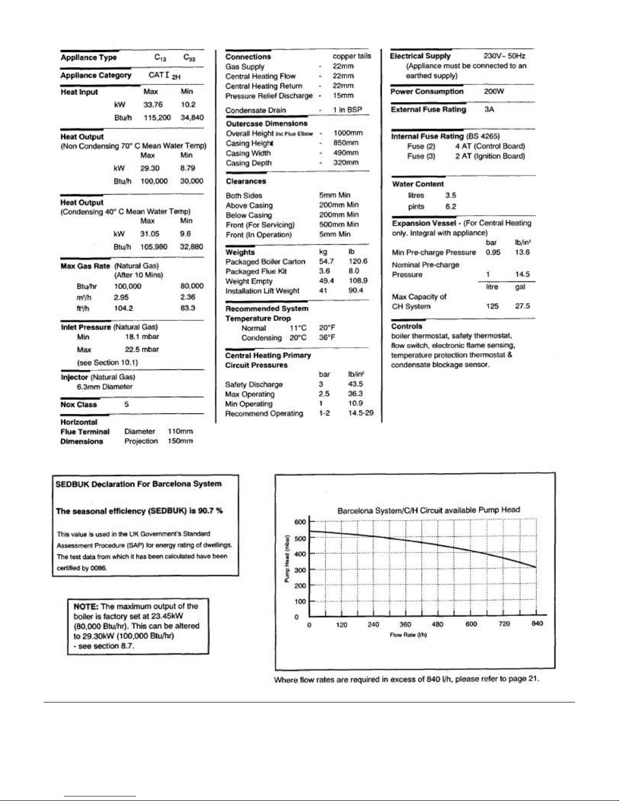
2. The maximum output of the boiler is preset at 80,000
Btu/hr. The boiler will automatically adjust down to 30,000
Btu/hr according to the system load. If required, the output
can be set to 100,000 Btu/hr. Please refer to section 8.7.
3. It is designed for use on Natural Gas (G20).
4. The boiler is suitable for sealed central heating and
domestic hot water systems.
“Benchmark” Log Book
As part of the industry-wide “Benchmark” intiative all Baxi
boilers now include an Installation, Commissioning and
Service Record Log Book. Please read the Log Book
carefully and complete all sections relevant to the appliance
and installation. These include sections on the type of
controls employed, flushing the system, burner operating
pressure etc. The details of the Log Book will be required in
the event of any warranty work. Also, there is a section to be
completed at each subsequent regular service visit.
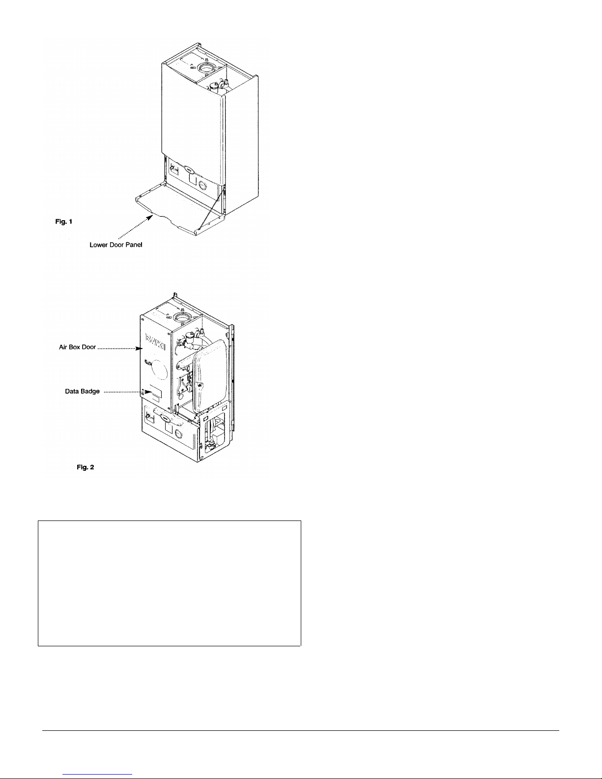
5. A label giving details of the model, serial number and Gas
Council number is situated on the rear of the lower door
panel (Fig. 1).
6. The boiler data badge is positioned on the air box door
(Fig. 2).
7. The boiler is intended to be installed in residential /
commercial / light industrial E.M.C. environments on a
governed meter supply only.
8. The boiler must be installed with one of the purpose
designed flues such as the standard horizontal flue kit, part
no 236921.
1.2 Optional Extras
KIT
FLUE EXTENSION KITS (110/70)
Flue Extension 0.25M
Flue Extension 0.5M
Flue Extension 1 M (use two kits for 2M etc.)
Flue Bend x 2 - 45o (Reduce all length of flue by 0.5m
when fitting this bend)
Flue Bend - 90o(Reduce overall length of flue by 1m
when fitting each bend)
VERTICAL FLUE (110/70)
Vertical Flue Terminal
Vertical Boiler Connection
VERTICAL FLUE (80/80)
Kit Boiler Connection Twin
CONTROL ACCESSORIES
Integral Electronic Twin Channel Timer Kit
PART N
241692
241694
241695
241689
241687
242802
242886
242757
242834
o

2.0 General Layout - Page 5
2.1 Layout (Figs. 3,4 & 5)
1. Wall Plate
2. Flue Elbow
3. Heat Exchanger
4. Burner
5. Air Box
6. Fan Protection Thermostat
7. Fan Assembly
8. Condensate Trap
9. User Interface (optional timer available)
10. Gas Tap
11. Gas / Air Ratio Valve
12. Electronics Housing
13. Transformer
14. Flow Temperature Safety Thermostat - Black
15. Flow Temperature Thermistor - Red
16. Flow Switch (dry fire protection)
17. Circulation Pump
18. Automatic Air Vent
19. Pressure Relief Valve
20. Water Pressure Gauge
21. Expansion Vessel

3.0 Appliance Operation - Page 6
3.1
1. Pump Overrun: When the switched live to the boiler
switches on or the flow temperature is greater than the set
point or anti-cycle finishes then Pump Overrun occurs for 10
seconds (cold) or 60 seconds (hot). The pump is on while
the fan, spark generator and gas valve are off.
2. Fan Purge: When pump overrun has finished if the flow
temperature is less than that set on the thermostat knob then
Fan Purge occurs. The pump and fan are on while the spark
generator and gas valve are off.
3. Ignition: When fan purge has finished Ignition occurs.
The pump, fan, spark generator and gas valve are on. The
burner ignites at mid rate.
4. Burner On: When a flame is detected during the ignition
period then Burner On occurs. The pump, fan and gas valve
are on while the spark generator is off. Flow temperature is
controlled by varying the fan speed (and thereby the gas
rate) to achieve optimum operation.
5. Anti-cycle: When all the TRVs shut down during Burner
On or Pump Overrun finishes and flow temperature is
greater than set point then Anti-cycle occurs. The pump, fan,
spark generator and gas valve are switched off.
6. Ignition Lockout: When 5 ignition attempts have been
made without a flame being detected then Ignition Lockout
occurs. The pump, fan, spark generator and gas valve are
switched off. The lockout light flashes once a second. The
boiler can only be reset manually using the thermostat knob.
7. No Water Flow: When there is No Water Flow through
the boiler (indicated by the flow switch) then a continuous
cycle of Pump Overrun and Anti-cycle occurs.
4.0 Technical Data - Page 7
5.0 Dimensions and Fixings - Page 8
6.0 System Details - Page 9
6.1 Water Circulating Systems
1. The appliance is suitable for fully pumped sealed systems
only.
The following conditions should be observed on all
systems:
• The boiler must not be used with a direct cylinder.
• Drain cocks should be fitted to all system low points.
• All gas and water pipes and electrical wiring must be
installed in a way which would not restrict the servicing
of the boiler.
• Air vents should be fitted to all system high points.
• An air rejection separator is recommended to ensure
correct operation of all appliance components.
6.2 Treatment of Water Circulating Systems
• All recirculatory water systems will be subject to
corrosion unless an appropriate water treatment is
applied. This means that the efficiency of the system will
deteriorate as corrosion sludge accumulates within the
system, risking damage to pump and valves, boiler
noise and circulation problems.
• When upgrading existing systems that exhibit evidence
of sludging, it is advisable to clean the system prior to
treatment in order to remove any sludge and reduce the
likelihood of these deposits damaging new components.
• When fitting new systems flux will be evident within the
system, which can lead to damage of system
components.
• All systems must be thoroughly drained and flushed out.
The recommended flushing and cleansing agents are
Betz-Dearborn Sentinel X300 or X400 and Fernox
Superfloc Universal Cleanser which should be used
following the flushing agent manufacturer’s instructions.
• System additives - corrosion inhibitors and flushing
agents/descalers should be suitable for aluminium and
comply to BS 7593 requirements. The only system
additives recommended are Betz-Dearborn Sentinel
X100 and Fernox-Copal which should be used following
the inhibitor manufacturer’s instructions.
Failure to flush and add inhibitor to the system will
invalidate the appliance warranty.
• It is important to check the inhibitor concentration after
installation, system modification and at every service in
accordance with the manufacturer’s instructions. (Test
kits are available from inhibitor stockists.)
• For information or advice regarding any of the above
contact the Baxi Helpline.
6.0 System Details - Page 10
6.3 Pipework
1. The sizes of flow and return pipes from the boiler should
be determined by normal methods, according to the
requirements of the system. The connection to the boiler is
22mm (copper tail).
2. Due to space requirements at the rear of the tap bracket,
pipework should comprise of solder fittings.
3. A 20oC (36oF) drop in temperature across the system is
recommended for condensing boilers. Existing radiators may
be oversized and so allow this, but where radiator sizing is
marginal it may be advisable to retain a system temperature
drop of 11oC (20oF).
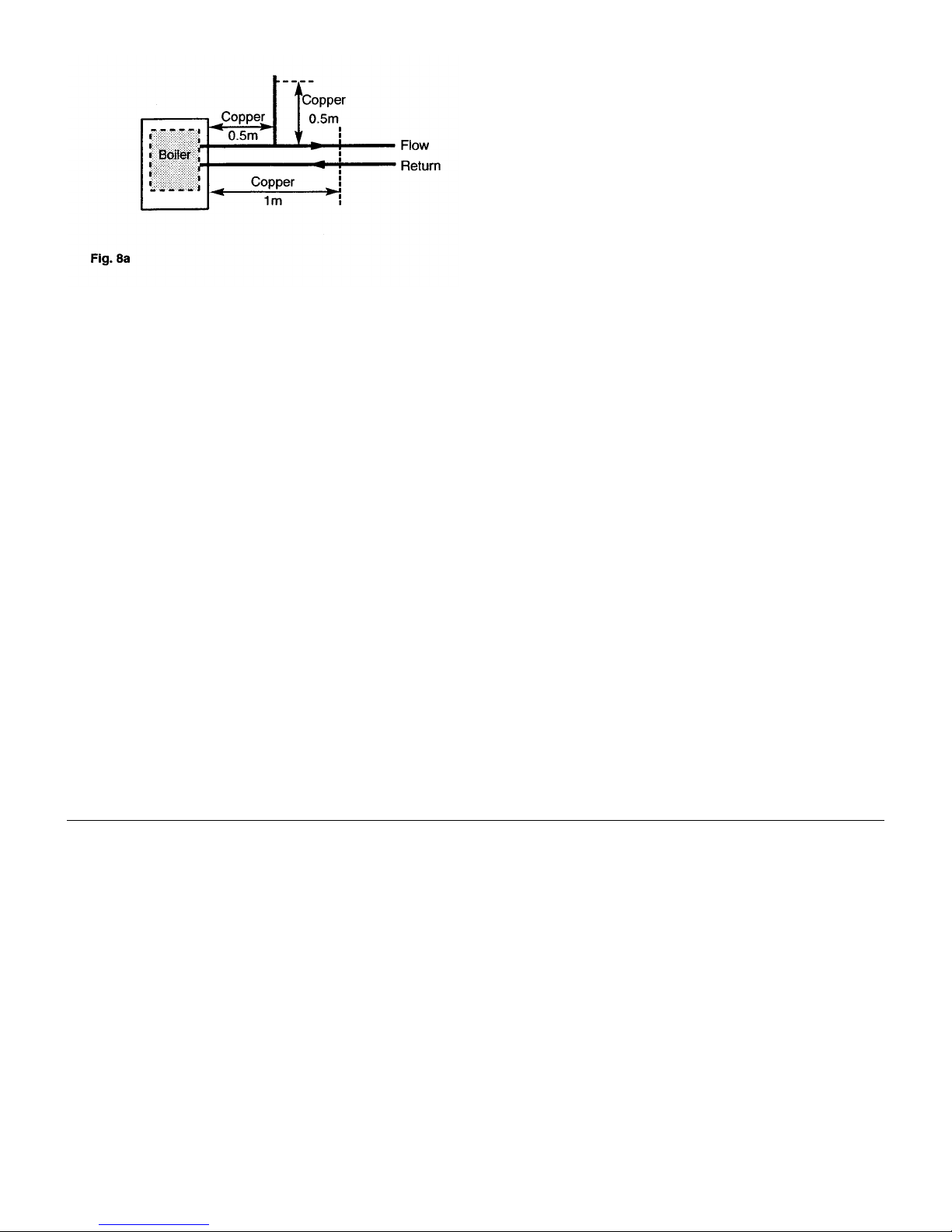
4. In systems using non-metallic pipework it is necessary to
use copper pipe for the boiler Flow and Return. The copper
must extend at least 1 metre from the boiler and include any
branches (Fig. 8a).
6.4 System Controls
1. For optimum operating conditions, the heating system
into which the boiler is installed should include a control
system.
2. Such a system will comprise of a timer control and
separate room or cylinder thermostats as appropriate. (An
integral twin channel programmer is available as an optional
extra).
3. The boiler should be controlled so that it operates on
demand only.
4. Operation of the system under control of the boiler
thermostat & TRV’s only does not produce the best results.
6.5 Thermal Stores
1. The Barcelona System Boiler must not be fitted to
thermal stores which override the boiler control system.
6.0 System Details - Page 11
6.6 System Filling and Pressurising
1. A filling point connection on the central heating return
pipework must be provided to facilitate initial filling and
pressurising and also any subsequent water loss
replacement/refilling.
2. The filling method adopted must be in accordance with all
relevant water supply bye-laws and use approved
equipment.
3. Your attention is drawn to: IRN 302 and Byelaw 14.
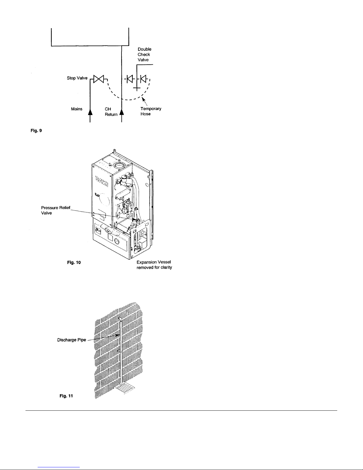
4. The sealed primary circuits may be filled or replenished
by means of a temporary connection between the circuit and
a supply pipe, provided a ‘Listed’ double check valve or
some other no less effective backflow prevention device is
permanently connected at the inlet to the circuit and the
temporary connection is removed after use (Fig. 9).
6.7 Expansion Vessel
(Central Heating only)
1. The appliance expansion vessel is pre-charged to 1 bar
(10 lb/in2). Therefore, the minimum cold fill pressure is 1 bar.
The vessel is suitable for correct operation for system
capacities up to 125 litres (27.5gal). For greater system
capacities an additional expansion vessel must be fitted refer to BS 7074 Pt 1.
6.8 Pressure Relief Valve (Figs. 10 & 11)
1. The pressure relief valve is set at 3 bar, therefore all
pipework, fittings, etc. should be suitable for pressures in
excess of 3 bar.
2. The pressure relief discharge pipe should be not less
than 15mm dia, run continuously downward, and discharge
outside the building, preferably over a drain, It should be
routed in such a manner that no hazard occurs to occupants
or causes damage to wiring or electrical components. The
end of the pipe should terminate facing down and towards
the wall.
3. The discharge must not be above a window, entrance or
other public access. Consideration must be given to the
possibility that boiling water/steam could discharge from the
pipe.
7.0 Site Requirements - Page 12
7.1 Information
WARNING - Check the information on the data plate is
compatible with local supply conditions.
1. The installation must be carried out by a CORGI Registered
Installer or other registered competent person and be in
accordance with the relevant requirements of the current GAS
SAFETY (Installation and Use) REGULATIONS, the BUILDING
REGULATIONS (Scotland)(Consolidation), the LOCAL BUILDING
REGULATIONS, the current L.E.E. WIRING REGULATIONS and the
bye laws of the LOCAL WATER UNDERTAKING.
Where no specific instruction is given reference should be made
to the relevant BRITISH STANDARD CODES OF PRACTICE.
For Ireland install in accordance with IS 813 “INSTALLATION OF
GAS APPLIANCES”. Reference should also be made to BRITISH
GAS GUIDANCE NOTES FOR THE INSTALLATION OF DOMESTIC GAS
CONDENSING BOILERS.
7.2 B.S. Codes of Practice
Standard Scope
BS 6891 Gas Installation.
BS 5546 Installation of hot water supplies for domestic
purposes.
BS 5449 Part 1 Forced circulation hot water systems.
BS 6798 Installation of gas fired hot water boilers.
BS 5440 Part 1 Flues.
BS 5440 Part 2 Ventilation.
BS 7074 Expansion vessels and ancillary equipment for
sealed water systems.
BS 7593 Treatment of water in domestic hot water central
heating systems.
WARNING - The addition of anything that may interfere with
the normal operation of the appliance without the express
written permission of Baxi Limited could invalidate the
appliance warranty and infringe the GAS SAFETY
(Installation and Use) REGULATIONS.
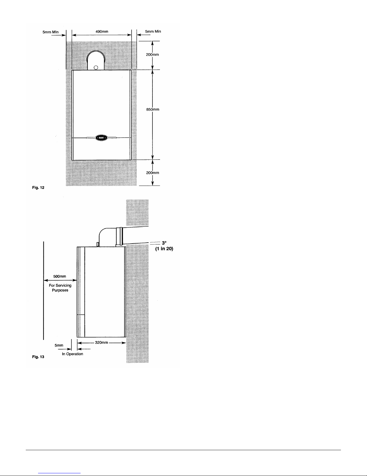
7.3 Clearances (Figs. 12 &13)
1. A flat vertical area is required for the installation of the boiler.
2. These dimensions include the necessary clearances around
the boiler for case removal, spanner access and air movement.
Additional clearances may be required for the passage of pipes
around local obstructions such as joists running parallel to the
front face of the boiler.
7.4 Location
1 The boiler may be fitted to any suitable wall with the flue
passing through an outside wall or roof and discharging to
atmosphere in a position permitting satisfactory removal of
combustion products and providing an adequate air supply. The
boiler should be fitted within the building unless otherwise
protected by a suitable enclosure i.e. garage or outhouse. (The
boiler may be fitted inside a cupboard - see Section 7.5).
2. If the boiler is sited in an unheated enclosure then it is
recommended to incorporate an appropriate device for frost
protection in the system controls.
3. If the boiler is fitted in a room containing a bath or shower
reference must be made to the current I.E.E. WIRING
REGULATIONS and BUILDING REGULATIONS. If the boiler is to be
fitted into a building of timber frame construction then reference
must be made to the Institute of Gas Engineers document UP 7.
7.0 Site Requirements - Page 13
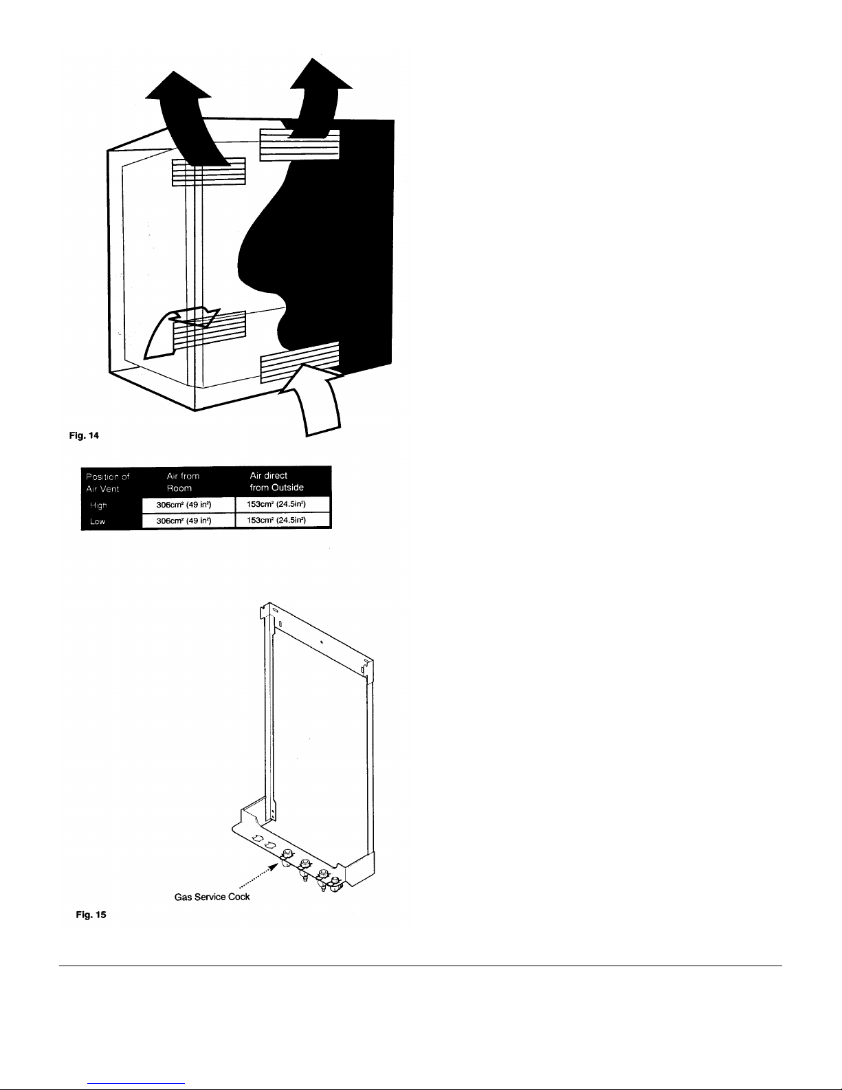
7.5 Ventilation of Compartments (Fig. 14)
1 Where the boiler is installed in a cupboard or
compartment, air vents are required (for cooling purposes) in
the cupboard or compartment at high and low level which
may communicate with a room or direct to outside air.
NOTE: Both air vents must communicate with the same
room or both be on the same wall to outside air.
2. Detailed recommendations for air supply are given in BS
5440: Part 2.
3. An existing cupboard or compartment may be used,
provided that it is modified for the purpose.
Recommendations for air supplies and details of essential
cupboard compartment design are given in BS 5440: Part 2.
7.6 Gas Supply
1. The gas installation should be in accordance with BS
6891.
2. The connection to the appliance is a 22mm copper tail
located at the rear of the gas service cock (Fig. 15).
3. Ensure that the pipework from the meter to the appliance
is of adequate size.
(22mm recommended at the appliance). Do not use pipes
of a smaller diameter than the boiler gas connection.
7.7 Electrical Supply
1. External wiring must be correctly earthed, polarised and
in accordance with current I.E.E. WIRING REGULATIONS.
2. The mains supply is 230V ~ 50Hz fused at 3A.
NOTE: The method of connection to the electricity
supply must facilitate complete electrical isolation of the
appliance. Connection may be via a fused double-pole
isolator with a contact separation of at least 3mm in all
poles and servicing the boiler and system controls only.
7.8 Condensate Drain
NOTE: Ensure the discharge of condensate complies
with any national or local regulations in force.
1. The condensate outlet terminates in a 1” BSP nut and
seal for the connection of 21.5mm (¾ in) plastic overflow
pipe which should generally discharge internally into the
household drainage system. If this is not possible, discharge
into an outside drain is acceptable.
2. The pipe should run internally as much as possible and
with a 10o (1 in 6) fall to dispose of condensate quickly to
avoid freezing.
7.0 Site Requirements - Page 14
7.9 Flue
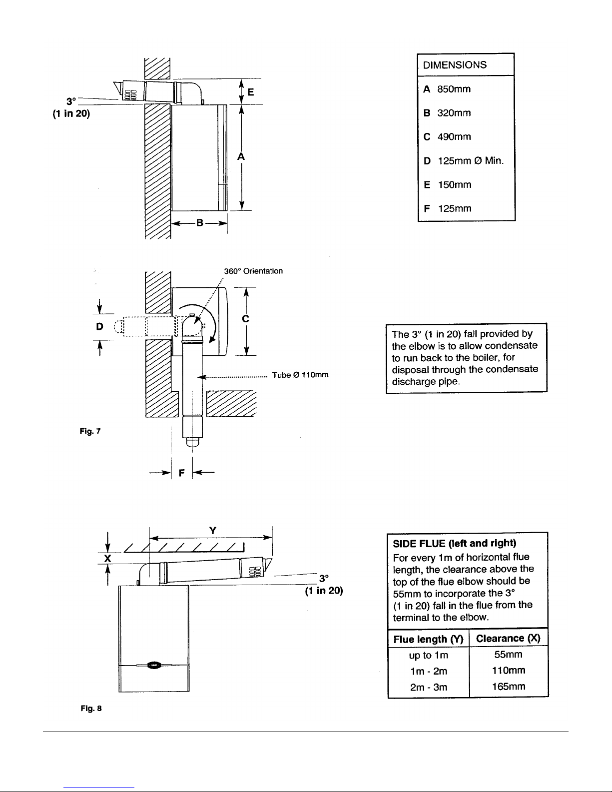
NOTE: Due to the nature of the boiler a plume of water
vapour will be discharged from the flue. This should be
taken into account when siting the flue terminal.
1. The following guidelines indicate the general
requirements for siting balanced flue terminals.
Recommendations for flues are given in BS 5440 Pt.1.
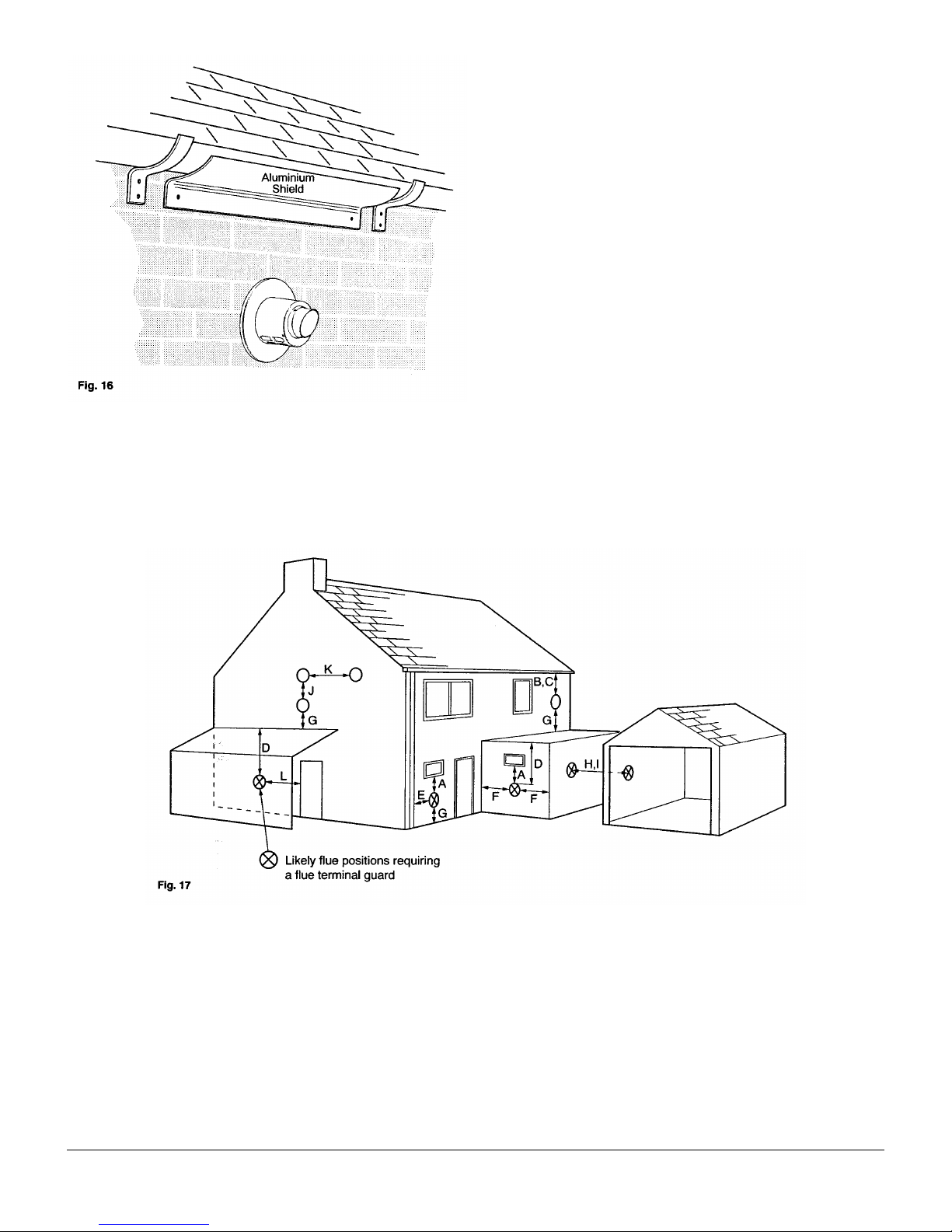
2. If the terminal is fitted within 1 metre (39 in) of a plastic
gutter, within 500mm (19½in) of a painted eave or a painted
gutter, an aluminium shield of at least 1 metre (39 in) long
should be fitted to the underside of the gutter or painted
surface. An air space of 5mm (3/16 in) should be left between
shield and gutter (Fig. 16).
3. If the terminal discharges onto a pathway or passageway,
check that combustion products will not cause a nuisance
and that the terminal will not obstruct the passageway.
4. Take into consideration the effect the plume of vapour
may have on neighbours when siting the flue.
5. If a terminal is less than 2 metres (783/4in) above a
balcony, above ground or above a flat roof to which people
have access, then a suitable terminal guard must be
provided.
Terminal Position with Minimum Distance (Fig.17) (mm)
A Directly below an openable window or other
opening, e.g. an air brick. 300
B Below gutters, soil pipes or drain pipes. 75
C Below eaves. 200
D Below balconies or car port roof. 200
E From vertical drain pipes and soil pipes. 75
F From internal or external corners. 300
G Above ground, roof or balcony level. 300
H From a Surface facing a terminal. 600
I From a terminal facing a terminal. 1200
J Vertically from a terminal on the same wall. 1500
K Horizontally from a terminal on the same wall. 300
L For an opening in a car port (e.g. door, window)
into a dwelling. 1200
 Loading...