

Page 1
Installation & User’s Instructions
for use with all Potterton Combination Boilers
Single Channel Wireless Programmable
Room Thermostat
Kit No5117391
Please leave these Instructions
with the User.
A
B
C
D
Comp No5117490 - Iss 5 - 11/06
BAXI
A Trading Division of Baxi Heating UK Ltd
Brooks House, Coventry Road, Warwick, CV34 4LL
After Sales Service 08706 096 096 Technical Enquiries 08706 049 049
Website www.potterton.co.uk
e&oe
company
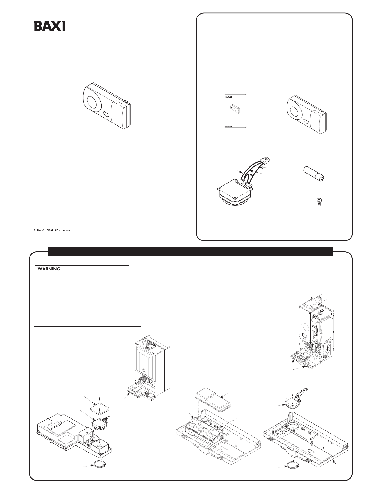
WARNING: Isolate at supply before access.
1. Undo the screws securing the boiler outer case and remove the boiler outer case.
2. Undo the screws retaining the facia and hinge the facia down.
3. If there is a Receiver Cover Panel then undo the screws and remove it.
4. From inside the facia panel, spring the securing barbs of the facia blanking plate and push
through the facia to release.
5. Take the receiver from the box and fit it to the facia panel.
NOTE: Do not fit the batteries to the transmitter at this stage.
Facia
Panel
Receiver
Facia Blanking
Plate
PCB removed
for clarity
PCB
Receiver
Cover Panel
SOCKET
1
/4Turn Facia
Securing Screws
Facia
Panel
Receiver
Receiver
Cover Panel
Facia Blanking
Plate
1
2
3
4
br -Brown
b - Blue
r - Red
br
b
r
E
FITTING THE RECEIVER TO THE BOILER
5
Installation & User’s Instructions
for use with all Baxi Combination Boilers
Single Channel Wireless Programmable
Room Thermostat
Kit No5117391
Please leave these Instructions
with the User.
Comp N
o
5117490 - Iss 1 - 12/05
Baxi Heating UK Limited
Brownedge RoadBamber Bridge Preston Lancashire PR5 6UP
After Sales Service 08706 096 096Technical Enquiries 08706 049 049
Website www.baxi.co.uk
KIT CONTENTS IDENTIFICATION
Key No Description No Off
A Instructions 1
B Programmable Room Thermostat (Transmitter) 1
C Receiver Unit 1
D Battery (1.5VL26/AA) 2
E Screw Plastite Pozi 3
Page 2

Optional Live
Feed For An
External Pump
Receiver
b
br
r
1. Ensure that there is power to the boiler.
2. Remove the rear panel of the transmitter, now correctly fit the batteries (2 x1.5V
LR6/AA) into the transmitter. The transmitter will start sending signals and within 10 - 20
seconds the receiver will pick up a signal, this can be confirmed by switching on the
transmitter to create a demand and observing the LED - see Operating Mode.
3. Secure the rear panel of the transmitter to a suitable wall in the living room or hall.
Refit the transmitter in place on the rear panel.
OPERATING RANGE: Within a building - up to 20 metres. Avoid positioning large
metallic objects, including mirrors, in the line - of - sight between the transmitter and
receiver.
NOTE: These components are ‘RF Linked’ and should be fitted as a pair, if they are
not, then recommissioning will be required.
RECOMMISSIONING
Press and hold the black button on the receiver, the LED light will flash immediately.
When it flashes again 2 or 3 seconds later release the button. The receiver LED light will
remain constantly ON, to indicate that it is now waiting for a corresponding signal from
the Programmable Room Thermostat Transmitter. The receiver will remain in this mode
for 3 minutes only.
The transmitter will start sending signals and within 10 - 20 seconds the receiver will pick
up a signal, this will be confirmed by the receiver’s LED light going off. The transmitter
and receiver are now ‘linked’ so that the receiver will switch ON and OFF according to
the settings on the Programmable Room Thermostat Transmitter.
Slot for Flat Bladed
Screwdriver
(twist slightly to release)
Batteries
Rear Panel
Programmable Room
Thermostat Transmitter
Black Button
LED Light
Receiver
OPERATING MODE
If the LED is Off then the Room Stat is Off.
If the LED is On then the Room Stat is On.
If the LED is Flashing once a second then the batteries
in the Room Stat are running out.
If the LED is Flashing 2 or 3 times a second then the
batteries in the Room Stat have run out.
If there is a 3-way Connector with a red wire looped between 2 pins near the Receiver
then proceed as follows:
Remove the Link Connector from the socket on the boiler harness and discard.
Connect the plug on the receiver harness into the socket.
Refit the Receiver Cover Panel, Facia and Outer Case.
Link
Connector
Socket
PCB
Receiver
Harness
Socket
PCB
Receiver
1
2
3
4
br -Brown
b - Blue
bl - Black
Red Wire
If there is a 3-way Block with 2 black, 1 blue and 1 brown wires connected near the
Receiver then proceed as follows:
Remove and discard the wiring harness on the receiver.
The Receiver wiring is integral to the boiler and the 3-way Block is only a temporary
connection for when there is no integral control fitted.
Remove and discard the 3-way Block.
Connect:
the black wires to terminals 3 and 4,
the blue wire to terminal 2,
the brown wire to terminal 1 of the Receiver,
terminal 5 is not used.
Refit the Receiver Cover Panel, Facia and Outer Case.
N12 3 4 5
To Set The Time: Slide the cover (A) off the unit. Rotate the timer clock clockwise
until the time is correct.
To Set The Central Heating ON/OFF Times: Move the tappets outwards for ON
times and inwards for OFF times.
To Set The Room Temperature: Rotate the room temperature dial until the desired
room temperature is selected.
To Set The Operating Mode: Slide the three position selector switch to the desired
position
On = Continuously on
Timed = Central Heating ON/OFF times
controlled by the tappets
Off = Continuously off
13
14
15
16
17
18
19
20
21
22
23
24
9
6
3
12
5°C
30°C
10
15
20
25
A
Room Temperature Dial
Quick Reference Guide
13
14
15
16
17
18
19
20
21
22
23
24
9
6
3
12
Off
On
Timed
Off Position
On Position
Time Pointer
Constant
Timed
Off
Rotate to
adjust time
Tappet
NOTE: Boiler is IPX0 when the receiver is fitted.
OPERATING RANGE: Within a building - up to 20 metres. Avoid positioning large metallic
objects, including mirrors, in the line - of - sight between the transmitter and receiver.
MAKING THE ELECTRICAL CONNECTIONS - There are 3 possible wiring arrangements (a) and (b) are the most common
FITTING THE PROGRAMMABLE ROOM THERMOSTAT SETTING THE PROGRAMMABLE ROOM THERMOSTAT
If there is no 3-way Block (a) and no 3-way Connector (b) then proceed as
follows:
Cut off the Receiver 3-way Plug and strip the 3 wires for connection into the
6-way terminal block - see Fig. 1.
Remove the link wire between terminals 1 & 2.
Wire the blue wire into the neutral terminal.
Wire the brown wire into the terminal 1.
Wire the red wire into terminal 2.
Refit the Receiver Cover Panel, Facia and Outer Case.
a
b
c
Link
Wire
N12 3 4 5
Optional Live
Feed For An
External Pump
Fig. 1
5
br
b
bl
3-way
Block
 Loading...