

Baxi 35/80 IE, 60/100 IE Installation & Servicing Instructions Manual
Installation & Servicing Instructions
Page 1
Natural Gas
Baxi System
35/80 IE & 60/100 IE
Gas Fired Wall Mounted System Boiler
Please keep these instructions safe.
Should you move house, please hand
them over to the next occupier.

Baxi System 35/80 IE
Baxi System 60/100 IE
Baxi is one of the leading manufacturers of domestic heating products in the UK.
Our first priority is to give a high quality service to our customers. Quality is designed into
every Baxi p roduct - prod ucts which f ulfil the dema nds and needs of customers , offering
choice, efficiency and reliability.
To keep ahead of changing trends, we have made a commitment to develop new ideas using
the latest technology - with the aim of continuing to make the products that customers want to
buy.
Everyone who works at Baxi has a commitment to quality because we know that satisfied
customers mean continued success.
We hope you get a satisfactory service from Baxi. If not, please let us know.
The boiler meets the requirements of Statutory Instrument " The Boiler (Efficiency)
Regulations 1993 No 3083" and is deemed to meet the requirements of Directive 92/42/EEC
on the energy efficiency requirements for new hot water boilers fired with liquid or gaseous
fuels:-
Type test for purpose of Regulation 5 certified by: Notified Body 0051.
Product/Production certified by: Notified Body 0051.
For IE only.
Baxi is a BS-EN ISO 9001
Accredited Company
Page 2
Contents

Section Page
1.0 Introduction
2.0 General Layout
3.0 Appliance Operation
4.0 Technical Data
5.0 Dimensions and Fixings
6.0 System Details
7.0 Site Requirements
8.0 Installation
9.0 Commissioning the Boiler
10.0 Completion
11.0 Servicing the Boiler
12.0 Changing Components
13.0 Illustrated Wiring Diagram
14.0 Fault Finding
15.0 Short Parts List
Page 3
40
4
5
6
7
9
10
12
17
26
28
29
31
39
43
1.0 Introduction
Baxi declare that no substances harmful to health are contained in the appliance or
used during appliance manufacture.
1.1 Description
1. The Baxi Sys tem 35/80 IE and 60/100 IE are fully automatic gas fired wall mounted system
boilers. They are room sealed and fan assisted.
2. The boilers are set to give a maximum output of 24.0kW (35/80 IE) or 29.3kW (60/100 IE).
3. They are designed for use on Natural Gas (G20) and can be converted to use Propane
(35/80 IE & 60/10 0 IE) or Butane (35/80 IE).
4. The boiler incorporat es a circulating pump and expansion vessel. It is suitable for use only
on fully pumped sealed s ystems.
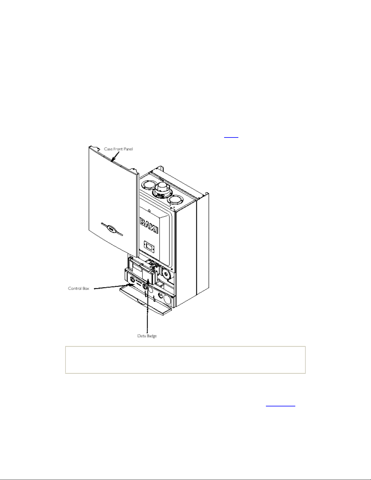
5. The boiler data badge gives details of the model and serial number and is situated on the
control box. It is visible when the case front panel is removed (Fig. 1
).
Fig. 1
NOTE:
This appliance must be installed in accordance with the manufacturer's
instructions and the regulations in force. Read the instructions fully before installing
or using the appliance.
6. The boiler is intended to be installed in residential / commercial / light industrial E.M.C.
environments on a governed meter supply only.
7. The boiler must be installed with one of the purpose designed flues such as the standard
horizontal flue kit, part no. 247719.
8. All systems must be thoroughly flushed and treated with inhibitor (see section 6.1
1.2 Installation
).
The installation must be carried out by a Competent Person and installed in accordance with
the current edition of I.S. 813 "Domestic Gas Installations", the current Building Regulations
and reference should be made to the current ETCI Rules for Electrical Installation.
1.3 Optional Extras
Various fl ue extensions, bends, vert ical flue kits ,control accessories etc. are available as
optional extras. These are detailed in a separate publication.
Page 4
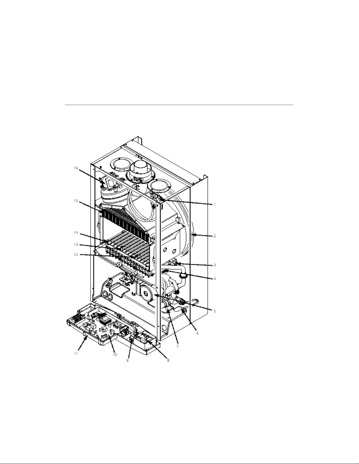
2.0 General Layout

2.1 Layout
1. Air Pressure Switch
2. Expansion Vessel
3. Burner Manifold
4. Automatic Air Vent
5. Circulation Pump
6. Drain Off Point
7. Pressure Relief Valve
8. DHW Relay PCB
9. System Pressure Gauge
10. PCB
11. Control Box
12. Flame Sensing Electrode
13. Spark Electrode
14. Burner
15. Primary Heat Exchanger
16. Fan Assembly
17. On/Off/Reset Selector Switch
18. Central Heating Temperature Control
19. F l am e Failure
20. Safety Thermostat
21. Fault on Fan or Flue
22. Fault on Pump or Low System Pressure
23. T em perature Indi c ation Only
24. Fault on Central Heating Sensor
25. Power On
26. Hot Water Mode
27. Central Heating Mode
28. Burner On
When neons 19 to 24 are constantly illuminated, they indicate the temperature of the central
heating water.
Page 5
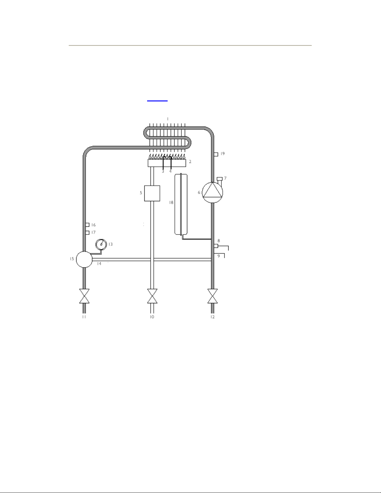
3.0 Appliance Operation
Boiler Prim ary Circuit
3.1 Operating Mode (Fig. 2)
Fig. 2
Key
1 Heat Exchanger
2 Burner
3 Ignition Electrode
4 Flame Sensing Electrode
5 Gas Valve
6 Pump
7 Automatic Air Vent
8 Pressure Relief Valve
9 Boiler Drain Point
10 Gas Inlet

11 Boiler Flow
12 Boiler Return
13 Pressure Gauge
14 Automatic By-Pass
15 Hydraulic Differential Pressure Sensor
16 Safety Thermostat
17 Central Heating Temperature Sensor
18 Expansion Vessel
19 Water Heating Sensor
1. With a demand for heating, the pump circulates water through the primary circuit. At a predetermined flow rate the hydraulic differential pressure switch operates, initiating the ignition
sequence.
2. The main burner ignites at low rate, then the gas valve controls the gas rate to maintain the
heating temperature measured by the temperature sensor.
3. When the flow temperature exceeds the setting temperature, a 3 minute delay occurs
before the burner relights automatically (anti-cycling). The pump continues to run during this
period.
4. When the demand is satisfied the burner is extinguished and the pump continues to run for
a period of 3 minutes (Pump Overrun).
IMPORTANT: When the selector switch is in the '0' (Off) position the electrical
supply to the boiler is isolated. The boiler will not operate.
3.2 Frost Protection Mode
1. The frost protection mode is integral to the appliance and functions only with the selector
switch (see Section 2.1
temperature falls below 5°C then the boiler will fire on its minimum setting until a flow
temperature of 30°C is reached. This will only protect the boiler, not the complete system.
Further protection can be incorporated by using a system frost thermostat.
) in the domestic hot water and central heating position. If the system
3.3 Pump Protection
1. With the selector switch (see Section 2.1) in either the central heating or central heating
and hot water position the pump will automatically operate for 1 minute in every 24 hours to
prevent stic king.
Page 6
4.0 Technical Data
4.1 System 35/80 IE
Appliance Type
Appliance Category
Heat Input (Gross)
C
C
12
CATⅡ
2H 3+
32
Max Min

kW 26.3 10.6
Btu/h 89,739 36,170
Heat Output
Max Min
kW 24.0 9.3
Btu/h 81,891 31,740
Max Gas Rate
m3/h 2.75
ft3/h 98.12
Burner Pressure
(Natural Gas - G20)
(After 10
Mins)
(Natural Gas - G20)
Max Rate Min Rate
mbar 12.2 ±0.5 2.5 ±0.5
in wg 4.88 ±0.2 1.0 ±0.2
Inlet Pressure
mbar 20
in wg 8
(Natural Gas - G20)
Burner Injector (Natural Gas - G20)
12 x 1.28mm Diameter
Electrical Supply
230V~ 50H
z
(Appliance must be connected to an earthed supply)
Power Consumption
External Fuse
Rating
170W
3A Maximum
Internal Fuse Rating
Fuse 2A Fast Blow to BS 4265
Electrical Protection
IPX5D
NOx
Class
3
Flue Terminal
Dimensions
Connections
Diameter 100mm
Projection 95mm
copper tails
Gas Supply - 3/4"
Central Heating Flow - 3/4"
- 3/4"

Return
Pressure Relief
Discharge
- 1/2"
Outercase Dimensions
Casing Height - 780mm
Overall Height Inc
Flue Elbow
- 980mm
Casing Width - 450mm
Casing Depth - 345mm
Clearances
Both Sides 5 mm Min
Above Casing 200 mm Min
Below Casing 200 mm Min
Front 450 mm Min (For Servicing)
Front 5 mm Min (In Operation)
Weights
Packaged Boiler
Carton
kg
45
Packaged Flue Kit 3
Installation Lift
Weight
37
Central Heating Primary Circuit Pressures
bar
Safety Discharge 3
Max Operating 2.5
Min Operating 0.2
Recommend Operating 1-2
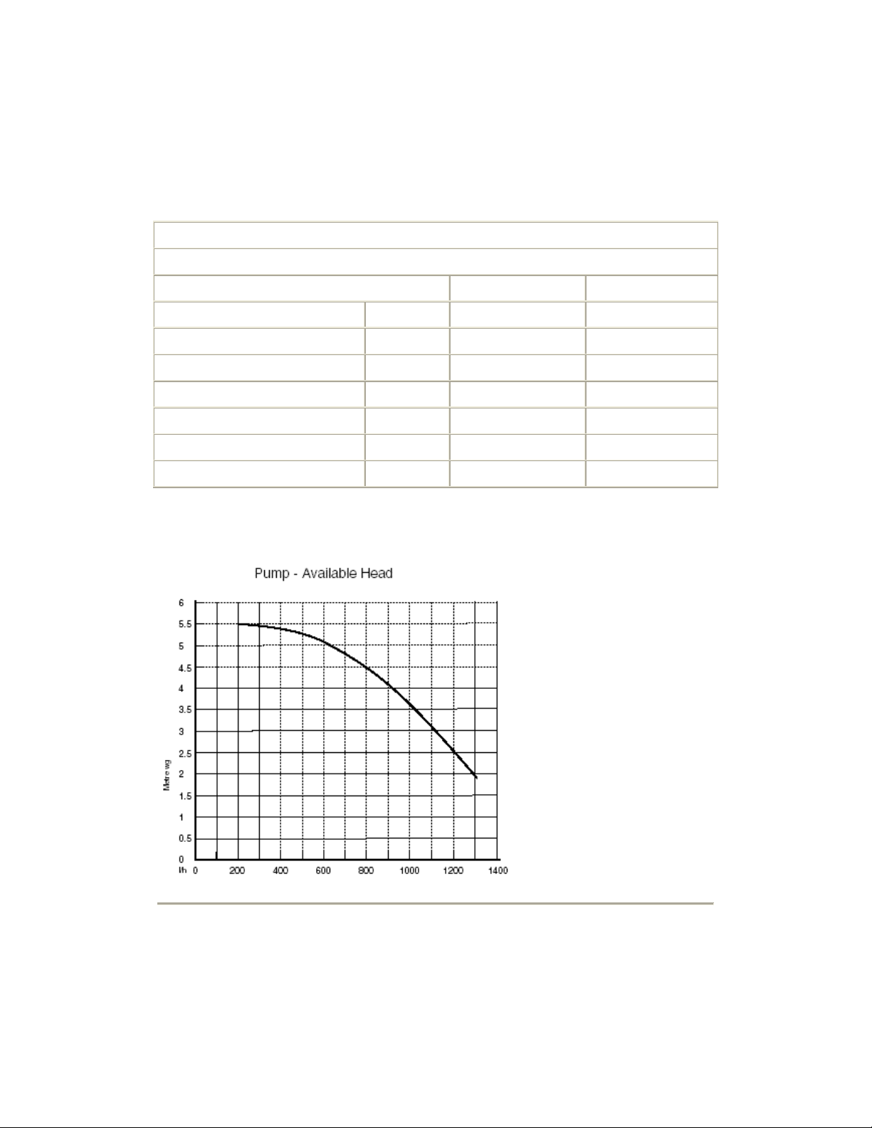
- Grundfos UP 15-60
Pump
Available Head See graph below
Expansion Vessel
bar
Min Pre-charge
Pressure
litre
Max Capacity of
CH System
- (Integral with appliance)
0.5
125
1.0
Content of Boiler
(unpressurised)
Temperatures
C.H. Flow Temp (
adjustable)
35°C to 85°C
max (±5°C)
LPG Gases Propane - G31 and Butane - G30
Burner Injector 12 x 0.65mm diameter
Burner Pressure
Max Rate Min Rate
Propane mbar 36.2 ±0.5 10.8 ±0.5
in wg 14.5 ±0.2 4.3 ±0.2
Butane mbar 28.8 ±0.5 7.7 ±0.5
in wg 11.5 ±0.2 3.1 ±0.2
Inlet Pressures
Propane Butane
mbar 37 28/30
in wg 14.8 11.2
SEDBUK Declaration For System Boiler 35/80 IE
The seasonal efficiency (SEDBUK) is 78.6 %
This value is used in the UK Government's Standard Assessment Procedure (SAP) for
energy rating of dwellings. The test data from which it has been calculated have been certified
by 0051.
Page 7
C
Appliance Type
Appliance Category
C
12
CATⅡ
2H 3P
32
Heat Input (Gross)
Max Min

kW 32.6 11.9
Btu/h 111,250 40,610
Heat Output
Max Min
kW 29.4 10.4
Btu/h 100,330 35,490
Max Gas Rate
(Natural Gas - G20)
(After 10 Mins)
m
3
/h 3.45
ft3/h 122
Burner Pressure
(Natural Gas - G20)
Max Rate Min Rate
mbar 12.5 ±0.5 1.8 ±0.5
in wg 5.0 ±0.2 0.7 ±0.2
Inlet Pressure (Natural Gas - G20)
mbar 20
in wg 8
Burner Injector
(Natural Gas - G20)
15 x 1.28mm Diameter
Electrical Supply
(Appliance must be connected
to an earthed supply)
Power Consumption
External Fuse
Rating
230V~ 50H
190W
3A Maximum
Internal Fuse Rating
Fuse 2A Fast Blow to BS 4265
Electrical Protection
IPX5D
NOx
Class
3
Flue Terminal
Dimensions
Connections
Diameter 100mm
Projection 95mm
copper tails
Gas Supply - 3/4"
Central Heating Flow - 3/4"
z
- 3/4"

Return
Pressure Relief
Discharge
- 1/2"
Outercase Dimensions
Casing Height - 780mm
Overall Height Inc
Flue Elbow
- 980mm
Casing Width - 450mm
Casing Depth - 345mm
Clearances
Both Sides 5 mm Min
Above Casing 200 mm Min
Below Casing 200 mm Min
Front 450 mm Min (For Servicing)
Front 5 mm Min (In Operation)
Weights
Packaged Boiler
Carton
kg
47
Packaged Flue Kit 3
Installation Lift
Weight
Central Heating Primary Circuit Pressures
39
bar
Safety Discharge 3
Max Operating 2.5
Min Operating 0.2
Recommend Operating 1-2
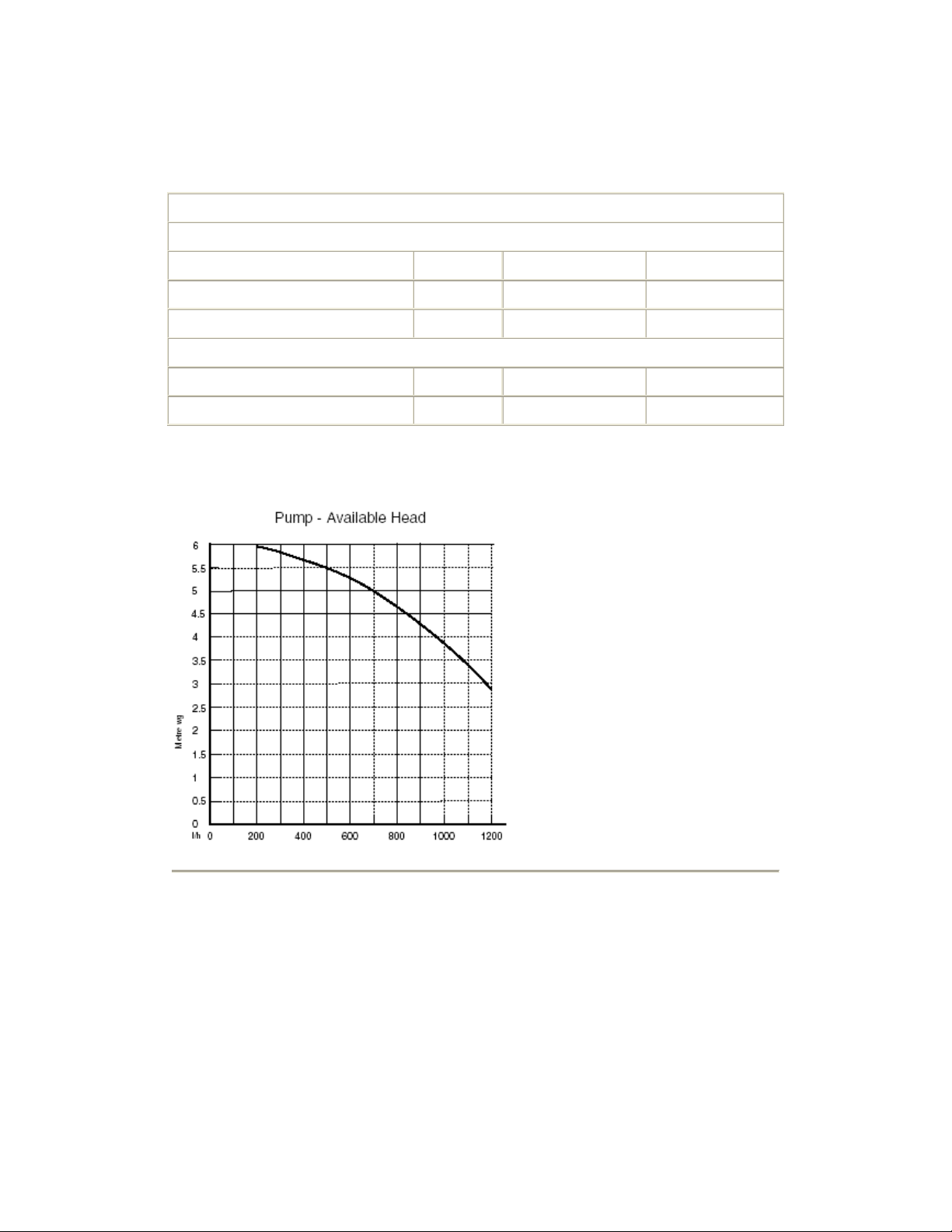
Pump -
Grundfos UP 15-60
Available Head See graph below
Expansion Vessel
- (For Central Heating only. Integral with appliance)
bar
Min Pre-charge Pressure 0.5
litre
Max Capacity of CH System 125
Primary Water Content of
Boiler (unpressurised)
1.1
Temperatures
C.H. Flow Temp (
35°C to 85°C
LPG Gases Propane - G31
adjustable)
max (±5°C)
Burner Injector 15 x 0.77mm diameter
Burner Pressure
Max Rate Min Rate
Propane mbar 34.4 ±0.5 5.1 ±0.5
in wg 13.8 ±0.2 2.0 ±0.2
Inlet Pressures
mbar 37
in wg 14.8
SEDBUK Declaration For System Boiler 60/100 IE
The seasonal efficiency (SEDBUK) is 78.2 %
This value is used in the UK Government's Standard Assessment Procedure (SAP) for
energy rating of dwellings. The test data from which it has been calculated have been certified
by 0051.
Page 8
5.0 Dimensions and Fixings
Dimensions
780mm
A
345mm
B
450mm
C
107mm Ø Min.
D
200mm
E
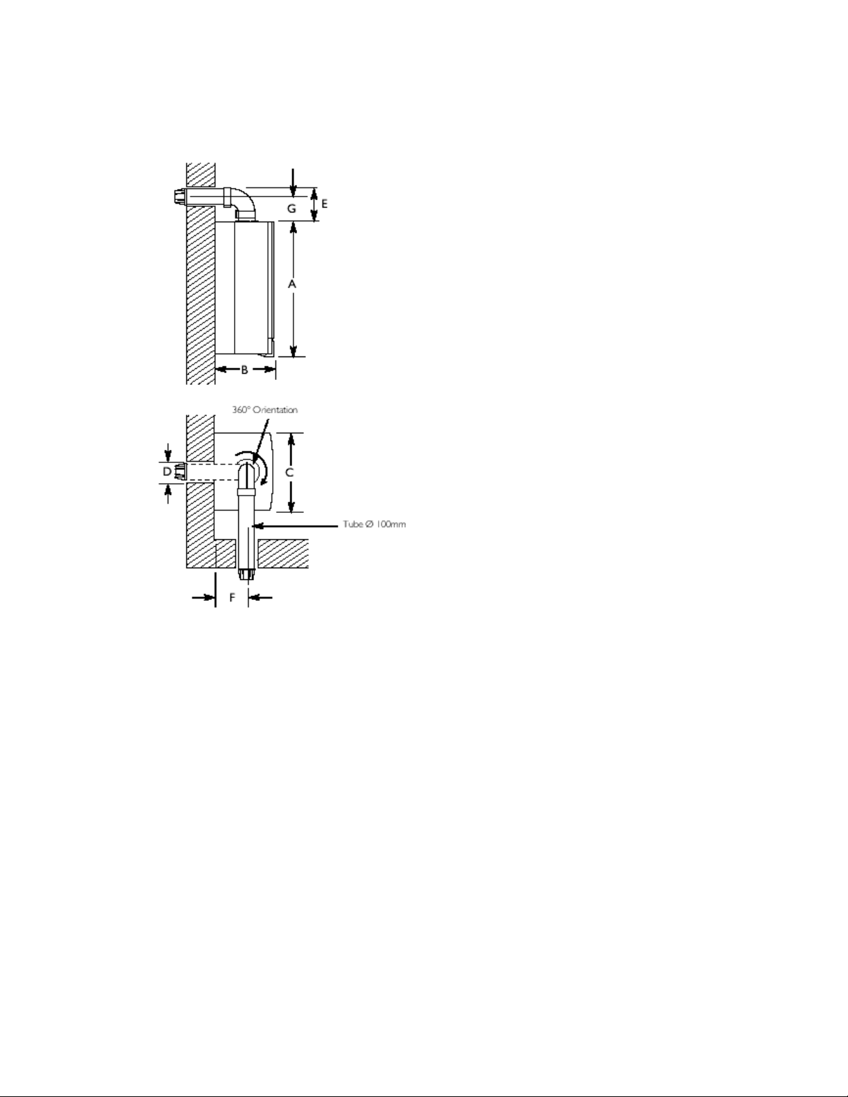
F
G
190mm
143mm
Page 9
6.0 System Details
6.1 Central Heating Circuit
1. The appliance is suitable for fully pumped SEALED SYSTEMS ONLY.
Treatment of Water Circulating Systems
• All recirculatory water systems will be subject to corrosion unless an appropriate
water treatment is applied. This means that the efficiency of the system will
deteriorate as corrosion sludge accumulates within the system, risking damage to
pump and valves, boiler noise and circulation problems.

• For opt i mum performa nce after ins tallation this boiler and its associated central
heating system must be flushed. A means of achieving this is by following the
guidelines given in BS 7593 "Treatment of water in domestic hot water central
heating system s " .
• This must involve the use of a proprietary cleanser, such as BetzDearborn Sentinel
X300 or X400, or Fernox Superfloc. Full instructions are supplied with the product s,
but for immediate information please contact BetzDearborn (+44 151 420 9563) or
Fernox (+44 1799 550 811) directly.
• For long term protection against corrosion and scale, after flushing it is recommended
that an inhibitor such as BetzDearborn Sentinel X100, or Fernox MB-1 or Copal is
used. The correct dosing is obtained by following the guidelines given in BS 7593.
Failure to flush and add inhibitor to the system may invalidate the appliance
warranty.
• It is important to check the inhibitor concentration aft er installation, system
modification and at every service in accordance with the manufacturer's instructions.
(Test kits are available from inhibitor stockists.)
• For information or advice regarding any of the above contact Heatmerchants
Technical Enquiries on 090 - 6442303.
6.2 Bypass
1. The boiler is fitted with an automatic integral bypass.
6.3 System Control
1. The boiler is designed for use in a heating system that incorporates external controls, i.e. a
minimum of a time r device.
Page 10
6.4 System Filling and Pressurising
1. A filling point connection on the central heating return pipework must be provided to
facilitate initial filling and pressurising and also any subsequent water loss
replacement/refilling.
2. The filling method adopted must be in accordance with the relevant Water Supply
regulations and use approved equipment. Your attention is also drawn to the current edition of
I.S. 813.
3. The sealed primary circuits may be filled or replenished by means of a temporary
connection between the primary circuit and a supply pipe provided a 'listed' double check
valve or some other no less effective backflow prevention device is permanently connected at
the inlet to the circuit and the temporary connection is removed after use (Fig. 3
).
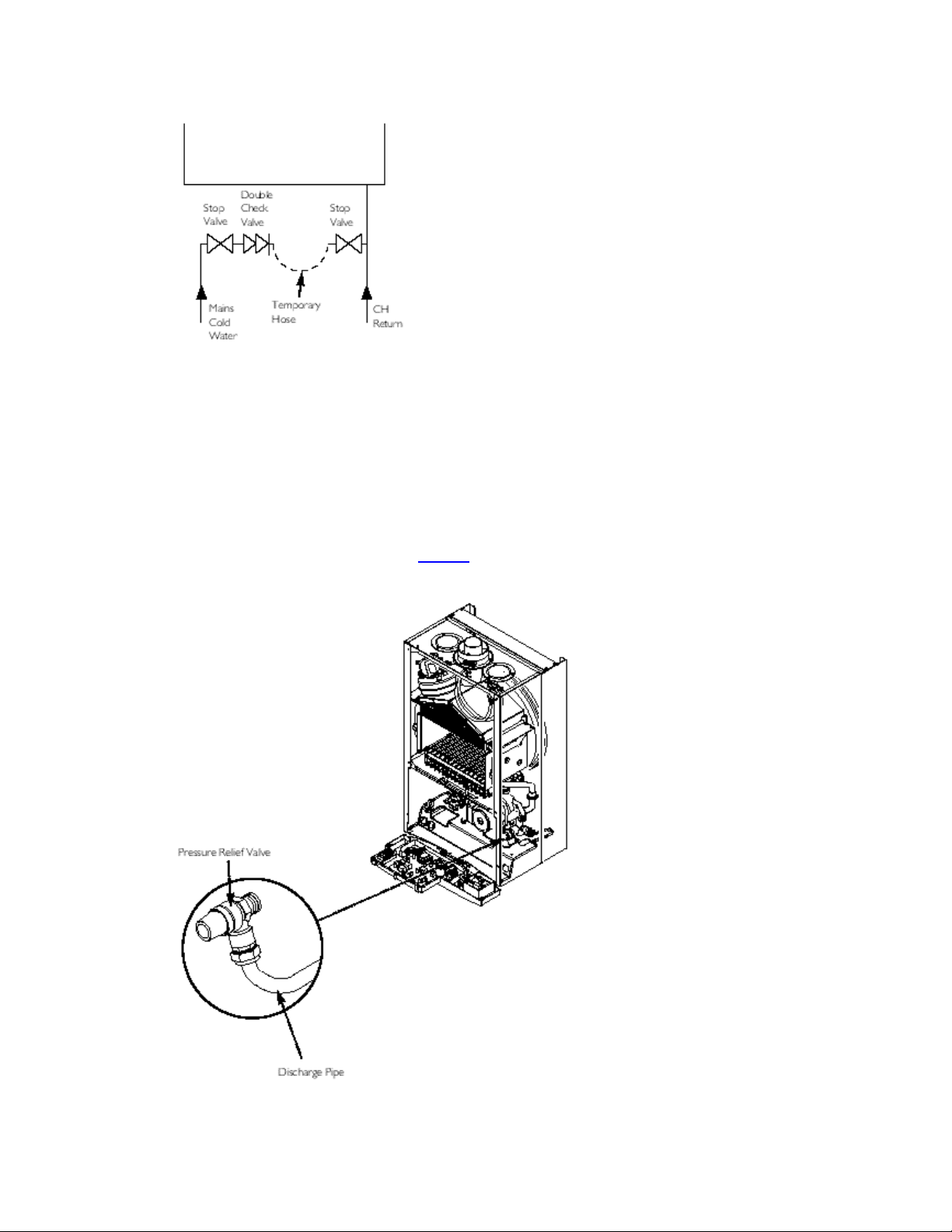
Fig. 3
4. There are connection points on the mains cold water inlet and central heating return
isolating taps to which the optional filling loop can be assembled.
6.5 Expansion Vessel
1. The appliance expansion vessel is pre-charged to 0.5 bar. The vessel is suitable for correct
operation for system capacities up to 125 litres. For greater system capacities an additional
expansion vessel must be fitted -refer to the current edition of I.S. 813.
6.6 Pressure Relief Valve (Fig. 4)
Fig. 4

1. The press ure relief valve is set at 3 bar, therefore all pipework, fittings, etc. should be
suitable for pressures in excess of 3 bar.
2. The pressure relief discharge pipe should be not less than 1/2" dia, run continuously
downward, and discharge outside the building, preferably ov er a drain. It should be rout ed in
such a manner that no hazard occurs to occupants or causes damage to wiring or electrical
components. The end of the pipe should terminate facing down and towards the wall.
3. The discharge must not be above a window, entrance or other public access.
Consideration must be given to the possibility that boiling water/steam could discharge from
the pipe.
Page 11
7.0 Site Requirements
7.1 Information
The installation must be carried out by a Competent Person and installed in accordance with
the current edition of I.S. 813 "Domestic Gas Installations", the current Building Regulations
and reference should be made to the current ETCI Rules for Electrical Installation.
7.2 Codes of Practice
Standard Scope
I.S. 813 Domestic Gas Installations.
BS 5546 Installation of hot water supplies for domestic purposes.
BS 5449 Part 1 Forced circulation hot water systems.
BS 7074 Expansion vessels and ancillary equipment for sealed water systems.
BS 7593 Treatment of water in domestic hot water central heating systems.
WARNING - The addition of anything that may interfere with the normal operation
of the appliance without the express written permission from the manufacturer or his
agent could invalidate the appliance warranty.
7.3 Clearances (Figs. 5 & 6)
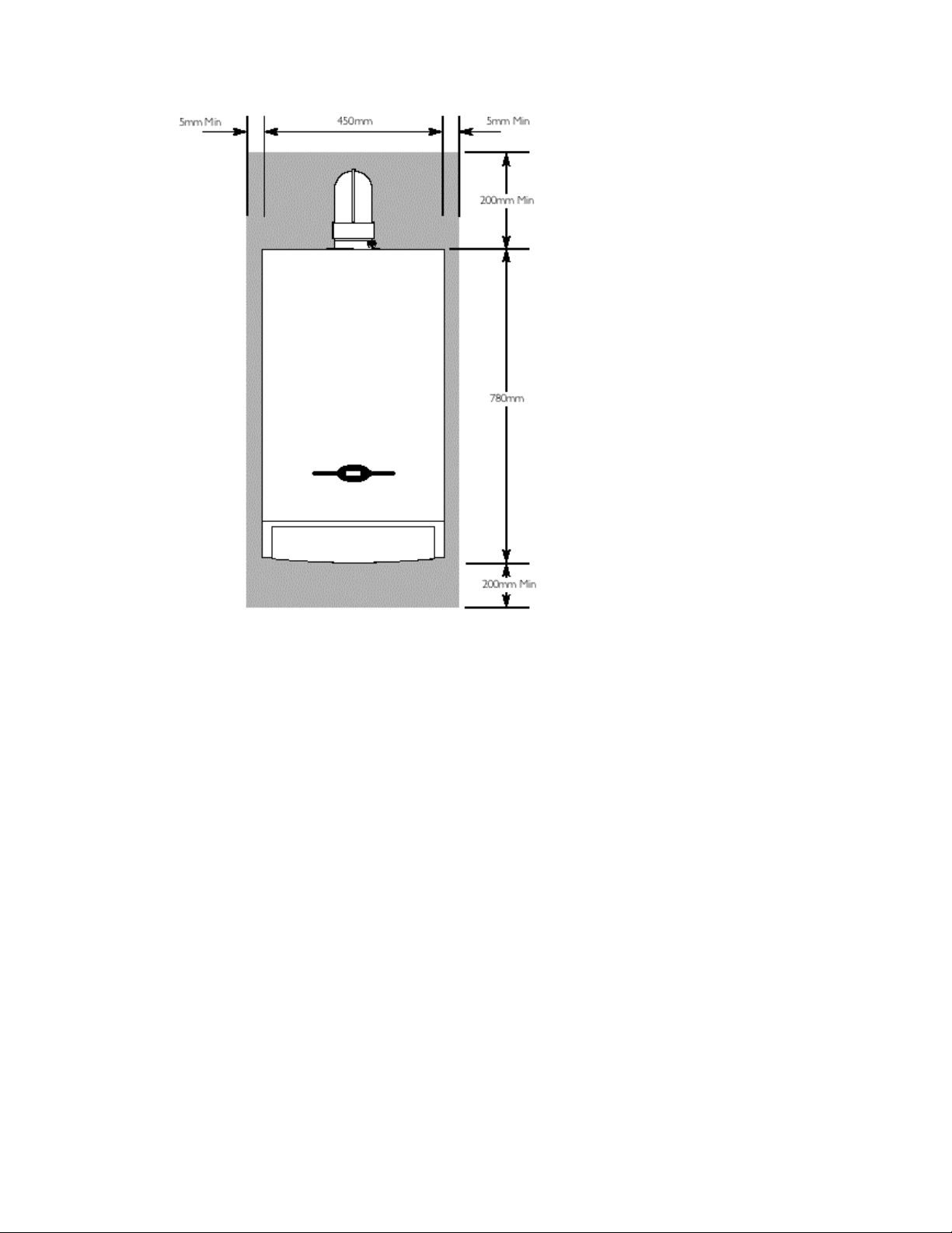
Fig. 5
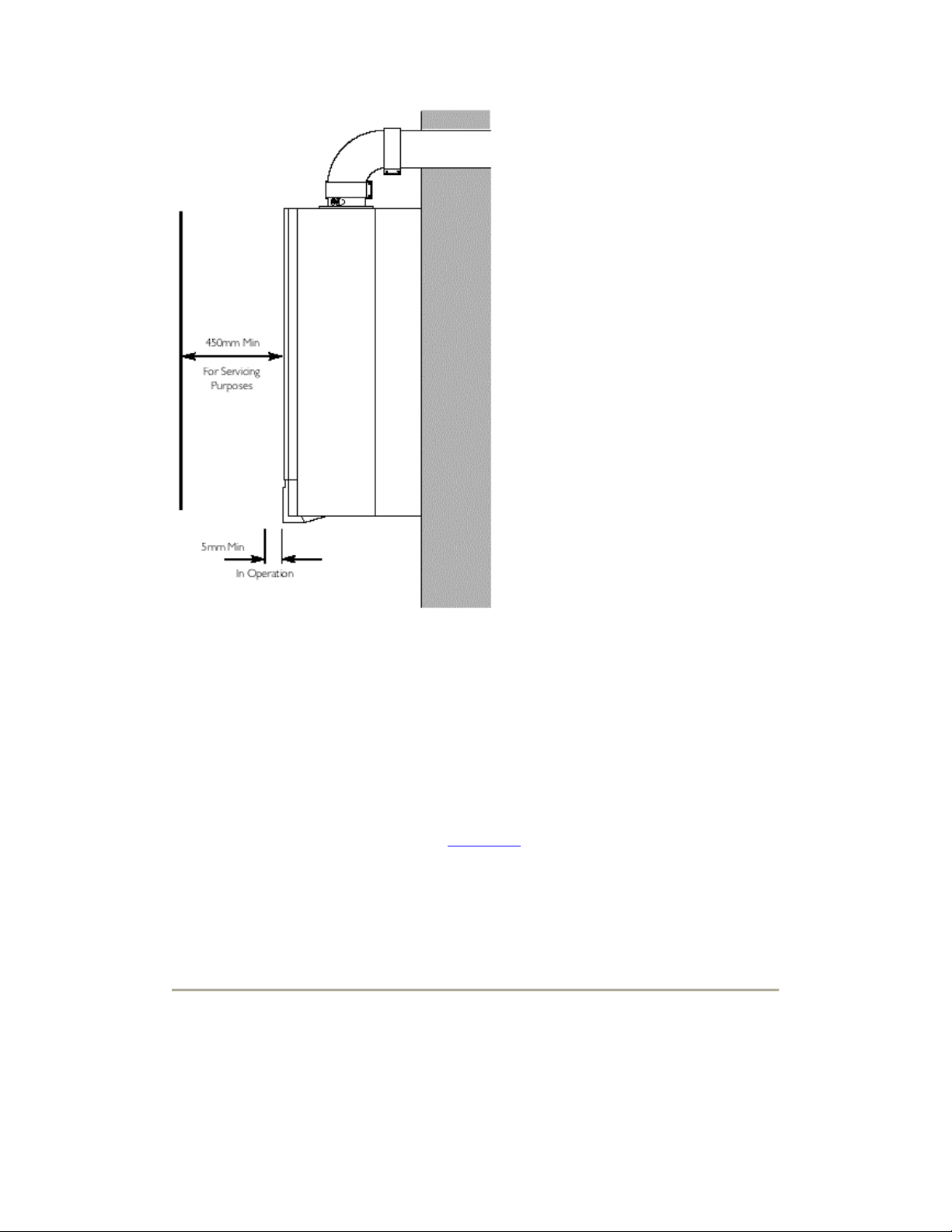
Fig. 6
1. A flat vertical area is required for the installation of the boiler.
2. These dimensions include the necessary clearances around the boiler for case removal,
spanner access and air movement. Additional clearances may be required for the passage of
pipes around local obstructions such as joists running parallel to the front face of the boiler.
7.4 Location
1. The boiler may be f it t e d to an y s uitable wall with the flue passing through an outside wall or
roof and discharging to atmosphere in a position permitting satisfactory removal of
combustion products and providing an adequate air supply. The boiler should be fitted within
the buildi ng unless otherwise protected by a sui table enclos ure i.e. gar age or outhouse. (The
boiler may be fitted inside a cupboard-see Section 7.5
2. If the boiler is sited in an unheated enclosure then it is recommended to leave the
On/Off/Reset Selector Switch in the domestic hot water and central heating position to give
frost protection.
3. If the boiler is fitted in a room containing a bath or shower reference must be made to the
current edition of I.S. 813 and the current ETCI Rules. If the boiler is to be fitted into a building
of timber frame construction then reference must be made to the current edition of Institution
of Gas Engineers Publication IGE/UP/7 (Gas Installations in Timber Framed Housing).
Page 12
).
7.5 Ventilation of Compartments
1. Where the appliance is installed in a cupboard or compartment, no air vents are required.
The appliance will run sufficiently cool without ventilation.
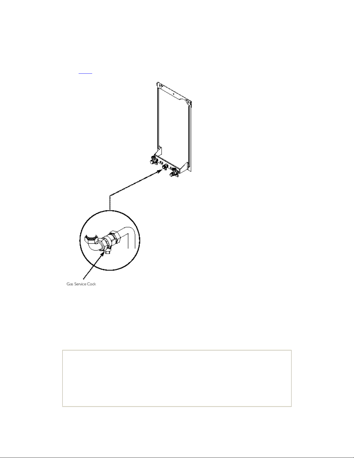
7.6 Gas Supply
1. The gas installation should be in accordance with the current edition of I.S. 813.
2. The connection to the appliance is a 3/4" copper tail located at the rear of the gas service
cock (Fig. 7
).
Fig. 7
3. Ensure that the pipework from the meter to the appliance is of adequate size. Do not use
pipes of a smaller diameter than the boiler gas connection (3/4").
7.7 Electrical Supply
1. External wiring must be correctly earthed, polarised and in accordance with current edition
of the ETCI Rules.
2. The mains supply must be 230V ~ 50H
NOTE: The method of connection to the electricity supply must facilitate
complete electrical isolation of the appliance.
Connection may be via a fused double-pole isolator with a contact separation
of at least 3mm in all poles and servicing the boiler and system controls only.
and fused at 3A maximum.
z
3. When the system includes an indirect domestic hot water cylinder it is recommended that a
cylinder thermostat is used in conjunction with a 3 port 2 position valve or 2 port zone valve.
4. A switched live feed should be taken from the cylinder thermostat to the boiler. This will
operate the boiler when there is a demand for domestic hot water (see Section 8.8
of suggested system wiring schemes).
Page 13
for details
7.8 Flue
1.
The flue terminal position must be in accordance with the recommendations given in
the current edition of I.S. 813.
2. The terminal shall be located in such a position that the wind can freely blow across it at all
times, that the products of combustion will not be blown into nearby air-entry grills or roof
spaces or cause discomfort to passers-by.
3. A suitable guard shall protect terminals located less than 2 m above any level, to which
people have normal access.
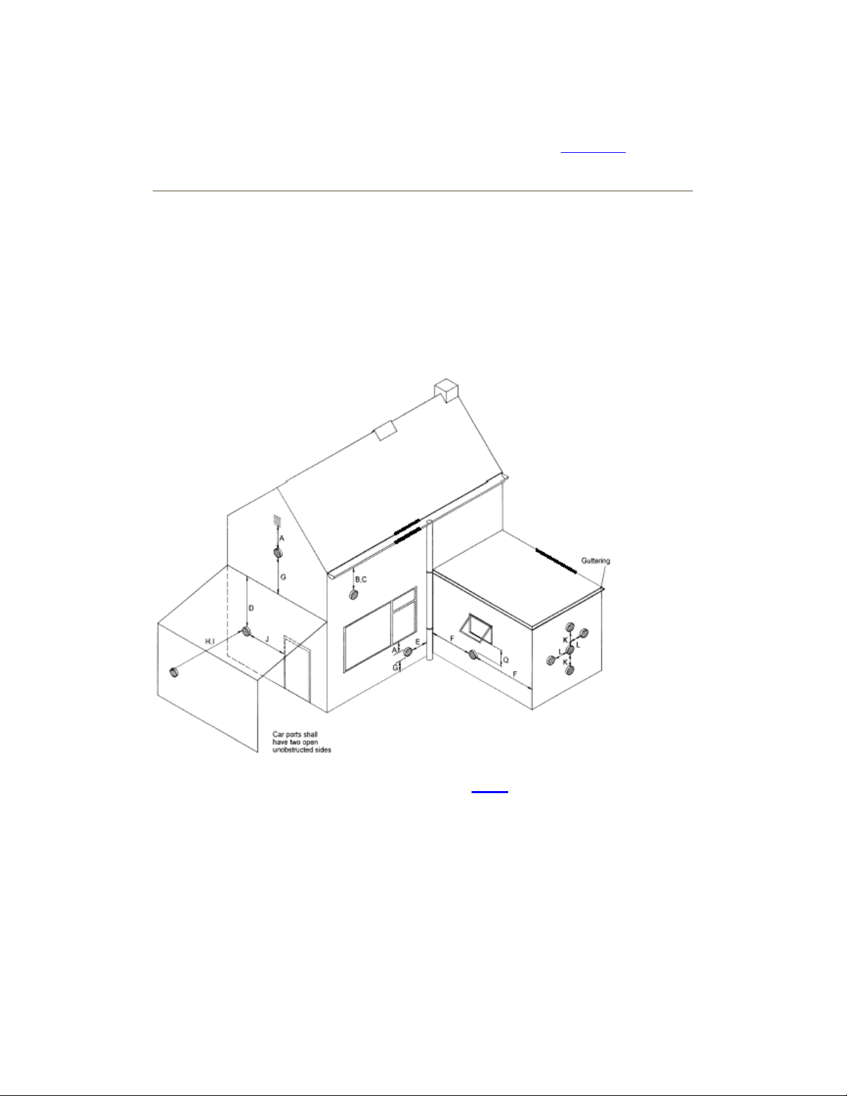
Fig. 9
Terminal Position with Minimum Distance (Fig. 9
)
(mm)
A Directly below opening vent, window, air brick etc. 300
B Below gutters, soil pipes. 25
C Below eaves. 25
D Below balconies/car port roof. 25
E From a vertical drain/soil pipe. 25
F From an internal/external corner. 25
G Above ground, roof or balcony level. 300
 Loading...