

baxi 224 Combi User guide

These instructions include the Benchmark Commissioning Checklist and should be left with the
user for safe keeping.They must be read in conjunction with the Flue Installation Guide.
United Kingdom
en
Installation and Service Manual
High Efficiency Wall Hung Condensing Gas Boiler
Baxi Combi
224 — 228 — 424 — 428

Dear Customer,
Thank you very much for buying this appliance.
Please read through the manual carefully before using the product, and keep it in a safe place for later reference. In order to
ensure continued safe and efficient operation we recommend that the product is serviced regularly. Our service and customer
service organisation can assist with this.
We hope you enjoy years of problem-free operation with the product.

Contents
7661586 - 2 - 12072016 3
Contents
1 Safety . . . . . . . . . . . . . . . . . . . . . . . . . . . . . . . . . . . . . . . . . . . . . . . . . . . . . . . . . . . . . . . . . . . . . . . . . . . . . . . . . . . . . . . . . . . . 6
1.1 Benchmark . . . . . . . . . . . . . . . . . . . . . . . . . . . . . . . . . . . . . . . . . . . . . . . . . . . . . . . . . . . . . . . . . . . . . . . . . . . . . . . . . . . 6
1.1.1 Building Regulations and the Benchmark Commissioning Checklist . . . . . . . . . . . . . . . . . . . . . . . . . . . . . . . .6
1.1.2 The Benchmark Scheme . . . . . . . . . . . . . . . . . . . . . . . . . . . . . . . . . . . . . . . . . . . . . . . . . . . . . . . . . . . . . . . . . 6
1.1.3 Installer Notification Guidelines . . . . . . . . . . . . . . . . . . . . . . . . . . . . . . . . . . . . . . . . . . . . . . . . . . . . . . . . . . . . 7
1.2 General safety instructions . . . . . . . . . . . . . . . . . . . . . . . . . . . . . . . . . . . . . . . . . . . . . . . . . . . . . . . . . . . . . . . . . . . . . . . 8
1.3 Recommendations . . . . . . . . . . . . . . . . . . . . . . . . . . . . . . . . . . . . . . . . . . . . . . . . . . . . . . . . . . . . . . . . . . . . . . . . . . . . . 9
1.4 Specific safety instructions . . . . . . . . . . . . . . . . . . . . . . . . . . . . . . . . . . . . . . . . . . . . . . . . . . . . . . . . . . . . . . . . . . . . . . . 9
1.4.1 Handling . . . . . . . . . . . . . . . . . . . . . . . . . . . . . . . . . . . . . . . . . . . . . . . . . . . . . . . . . . . . . . . . . . . . . . . . . . . . . .9
1.5 Liabilities . . . . . . . . . . . . . . . . . . . . . . . . . . . . . . . . . . . . . . . . . . . . . . . . . . . . . . . . . . . . . . . . . . . . . . . . . . . . . . . . . . . . 10
1.5.1 Manufacturer's liability . . . . . . . . . . . . . . . . . . . . . . . . . . . . . . . . . . . . . . . . . . . . . . . . . . . . . . . . . . . . . . . . . . 10
1.5.2 Installer's liability . . . . . . . . . . . . . . . . . . . . . . . . . . . . . . . . . . . . . . . . . . . . . . . . . . . . . . . . . . . . . . . . . . . . . . 10
1.5.3 User's liability . . . . . . . . . . . . . . . . . . . . . . . . . . . . . . . . . . . . . . . . . . . . . . . . . . . . . . . . . . . . . . . . . . . . . . . . .10
2 About this manual . . . . . . . . . . . . . . . . . . . . . . . . . . . . . . . . . . . . . . . . . . . . . . . . . . . . . . . . . . . . . . . . . . . . . . . . . . . . . . . . . . 12
2.1 General . . . . . . . . . . . . . . . . . . . . . . . . . . . . . . . . . . . . . . . . . . . . . . . . . . . . . . . . . . . . . . . . . . . . . . . . . . . . . . . . . . . . . 12
2.2 Additional documentation . . . . . . . . . . . . . . . . . . . . . . . . . . . . . . . . . . . . . . . . . . . . . . . . . . . . . . . . . . . . . . . . . . . . . . . 12
2.3 Symbols used . . . . . . . . . . . . . . . . . . . . . . . . . . . . . . . . . . . . . . . . . . . . . . . . . . . . . . . . . . . . . . . . . . . . . . . . . . . . . . . . 12
2.3.1 Symbols used in the manual . . . . . . . . . . . . . . . . . . . . . . . . . . . . . . . . . . . . . . . . . . . . . . . . . . . . . . . . . . . . . 12
2.4 Abbreviations/Glossary . . . . . . . . . . . . . . . . . . . . . . . . . . . . . . . . . . . . . . . . . . . . . . . . . . . . . . . . . . . . . . . . . . . . . . . . . 12
3 Technical specifications . . . . . . . . . . . . . . . . . . . . . . . . . . . . . . . . . . . . . . . . . . . . . . . . . . . . . . . . . . . . . . . . . . . . . . . . . . . . . 13
3.1 Homologations . . . . . . . . . . . . . . . . . . . . . . . . . . . . . . . . . . . . . . . . . . . . . . . . . . . . . . . . . . . . . . . . . . . . . . . . . . . . . . . 13
3.1.1 Directives . . . . . . . . . . . . . . . . . . . . . . . . . . . . . . . . . . . . . . . . . . . . . . . . . . . . . . . . . . . . . . . . . . . . . . . . . . . .13
3.1.2 Certifications . . . . . . . . . . . . . . . . . . . . . . . . . . . . . . . . . . . . . . . . . . . . . . . . . . . . . . . . . . . . . . . . . . . . . . . . . 13
3.1.3 Gas category . . . . . . . . . . . . . . . . . . . . . . . . . . . . . . . . . . . . . . . . . . . . . . . . . . . . . . . . . . . . . . . . . . . . . . . . . 13
3.1.4 Standards . . . . . . . . . . . . . . . . . . . . . . . . . . . . . . . . . . . . . . . . . . . . . . . . . . . . . . . . . . . . . . . . . . . . . . . . . . . 13
3.2 Technical data . . . . . . . . . . . . . . . . . . . . . . . . . . . . . . . . . . . . . . . . . . . . . . . . . . . . . . . . . . . . . . . . . . . . . . . . . . . . . . . .14
3.2.1 Technical information . . . . . . . . . . . . . . . . . . . . . . . . . . . . . . . . . . . . . . . . . . . . . . . . . . . . . . . . . . . . . . . . . . .14
3.2.2 Technical parameters . . . . . . . . . . . . . . . . . . . . . . . . . . . . . . . . . . . . . . . . . . . . . . . . . . . . . . . . . . . . . . . . . . 17
3.3 Dimensions and connections/clearances . . . . . . . . . . . . . . . . . . . . . . . . . . . . . . . . . . . . . . . . . . . . . . . . . . . . . . . . . . . 18
3.4 Electrical diagram . . . . . . . . . . . . . . . . . . . . . . . . . . . . . . . . . . . . . . . . . . . . . . . . . . . . . . . . . . . . . . . . . . . . . . . . . . . . . 20
4 Description of the product . . . . . . . . . . . . . . . . . . . . . . . . . . . . . . . . . . . . . . . . . . . . . . . . . . . . . . . . . . . . . . . . . . . . . . . . . . . . 22
4.1 General description . . . . . . . . . . . . . . . . . . . . . . . . . . . . . . . . . . . . . . . . . . . . . . . . . . . . . . . . . . . . . . . . . . . . . . . . . . . .22
4.2 Operating principle . . . . . . . . . . . . . . . . . . . . . . . . . . . . . . . . . . . . . . . . . . . . . . . . . . . . . . . . . . . . . . . . . . . . . . . . . . . . 22
4.2.1 Air-gas adjustment . . . . . . . . . . . . . . . . . . . . . . . . . . . . . . . . . . . . . . . . . . . . . . . . . . . . . . . . . . . . . . . . . . . . .22
4.2.2 Combustion . . . . . . . . . . . . . . . . . . . . . . . . . . . . . . . . . . . . . . . . . . . . . . . . . . . . . . . . . . . . . . . . . . . . . . . . . . 22
4.2.3 Heating and domestic hot water production . . . . . . . . . . . . . . . . . . . . . . . . . . . . . . . . . . . . . . . . . . . . . . . . . 23
4.3 Main components . . . . . . . . . . . . . . . . . . . . . . . . . . . . . . . . . . . . . . . . . . . . . . . . . . . . . . . . . . . . . . . . . . . . . . . . . . . . . 23
4.4 Control panel description . . . . . . . . . . . . . . . . . . . . . . . . . . . . . . . . . . . . . . . . . . . . . . . . . . . . . . . . . . . . . . . . . . . . . . . 23
4.4.1 Description of the keys . . . . . . . . . . . . . . . . . . . . . . . . . . . . . . . . . . . . . . . . . . . . . . . . . . . . . . . . . . . . . . . . . 23
4.4.2 Description of the display . . . . . . . . . . . . . . . . . . . . . . . . . . . . . . . . . . . . . . . . . . . . . . . . . . . . . . . . . . . . . . . .23
4.5 Standard delivery . . . . . . . . . . . . . . . . . . . . . . . . . . . . . . . . . . . . . . . . . . . . . . . . . . . . . . . . . . . . . . . . . . . . . . . . . . . . . 24
4.5.1 Contents of the carton . . . . . . . . . . . . . . . . . . . . . . . . . . . . . . . . . . . . . . . . . . . . . . . . . . . . . . . . . . . . . . . . . . 24
4.6 Accessories and options . . . . . . . . . . . . . . . . . . . . . . . . . . . . . . . . . . . . . . . . . . . . . . . . . . . . . . . . . . . . . . . . . . . . . . . . 24
4.6.1 Optional accessories . . . . . . . . . . . . . . . . . . . . . . . . . . . . . . . . . . . . . . . . . . . . . . . . . . . . . . . . . . . . . . . . . . . 24
5 Before installation . . . . . . . . . . . . . . . . . . . . . . . . . . . . . . . . . . . . . . . . . . . . . . . . . . . . . . . . . . . . . . . . . . . . . . . . . . . . . . . . . . 25
5.1 Installation regulations . . . . . . . . . . . . . . . . . . . . . . . . . . . . . . . . . . . . . . . . . . . . . . . . . . . . . . . . . . . . . . . . . . . . . . . . . 25
5.2 Installation requirements . . . . . . . . . . . . . . . . . . . . . . . . . . . . . . . . . . . . . . . . . . . . . . . . . . . . . . . . . . . . . . . . . . . . . . . .25
5.2.1 Gas supply . . . . . . . . . . . . . . . . . . . . . . . . . . . . . . . . . . . . . . . . . . . . . . . . . . . . . . . . . . . . . . . . . . . . . . . . . . .25
5.2.2 Electrical supply . . . . . . . . . . . . . . . . . . . . . . . . . . . . . . . . . . . . . . . . . . . . . . . . . . . . . . . . . . . . . . . . . . . . . . .25
5.2.3 Hard water area . . . . . . . . . . . . . . . . . . . . . . . . . . . . . . . . . . . . . . . . . . . . . . . . . . . . . . . . . . . . . . . . . . . . . . .25
5.2.4 Bypass . . . . . . . . . . . . . . . . . . . . . . . . . . . . . . . . . . . . . . . . . . . . . . . . . . . . . . . . . . . . . . . . . . . . . . . . . . . . . .25
5.2.5 System control . . . . . . . . . . . . . . . . . . . . . . . . . . . . . . . . . . . . . . . . . . . . . . . . . . . . . . . . . . . . . . . . . . . . . . . .26
5.2.6 Treatment of water circulating systems . . . . . . . . . . . . . . . . . . . . . . . . . . . . . . . . . . . . . . . . . . . . . . . . . . . . . 26
5.2.7 Showers . . . . . . . . . . . . . . . . . . . . . . . . . . . . . . . . . . . . . . . . . . . . . . . . . . . . . . . . . . . . . . . . . . . . . . . . . . . . .26
5.2.8 Expansion vessel (CH only) . . . . . . . . . . . . . . . . . . . . . . . . . . . . . . . . . . . . . . . . . . . . . . . . . . . . . . . . . . . . . .26
5.2.9 Pump available head . . . . . . . . . . . . . . . . . . . . . . . . . . . . . . . . . . . . . . . . . . . . . . . . . . . . . . . . . . . . . . . . . . . 27
5.2.10 Safety pressure relief valve . . . . . . . . . . . . . . . . . . . . . . . . . . . . . . . . . . . . . . . . . . . . . . . . . . . . . . . . . . . . . . 27
5.3 Choice of the location . . . . . . . . . . . . . . . . . . . . . . . . . . . . . . . . . . . . . . . . . . . . . . . . . . . . . . . . . . . . . . . . . . . . . . . . . . 27
5.3.1 Location of the boiler . . . . . . . . . . . . . . . . . . . . . . . . . . . . . . . . . . . . . . . . . . . . . . . . . . . . . . . . . . . . . . . . . . . 27
5.3.2 Data plate and service label . . . . . . . . . . . . . . . . . . . . . . . . . . . . . . . . . . . . . . . . . . . . . . . . . . . . . . . . . . . . . 28

Contents
4 7661586 - 2 - 12072016
5.3.3 Bath and shower rooms . . . . . . . . . . . . . . . . . . . . . . . . . . . . . . . . . . . . . . . . . . . . . . . . . . . . . . . . . . . . . . . . .29
5.3.4 Ventilation . . . . . . . . . . . . . . . . . . . . . . . . . . . . . . . . . . . . . . . . . . . . . . . . . . . . . . . . . . . . . . . . . . . . . . . . . . . 29
5.3.5 Condensate drain . . . . . . . . . . . . . . . . . . . . . . . . . . . . . . . . . . . . . . . . . . . . . . . . . . . . . . . . . . . . . . . . . . . . . 29
5.3.6 Clearances . . . . . . . . . . . . . . . . . . . . . . . . . . . . . . . . . . . . . . . . . . . . . . . . . . . . . . . . . . . . . . . . . . . . . . . . . . .32
5.3.7 Flue/chimney location . . . . . . . . . . . . . . . . . . . . . . . . . . . . . . . . . . . . . . . . . . . . . . . . . . . . . . . . . . . . . . . . . . 32
5.3.8 Horizontal flue/chimney systems . . . . . . . . . . . . . . . . . . . . . . . . . . . . . . . . . . . . . . . . . . . . . . . . . . . . . . . . . . 34
5.3.9 Flue/chimney trim . . . . . . . . . . . . . . . . . . . . . . . . . . . . . . . . . . . . . . . . . . . . . . . . . . . . . . . . . . . . . . . . . . . . . 34
5.3.10 Terminal guard . . . . . . . . . . . . . . . . . . . . . . . . . . . . . . . . . . . . . . . . . . . . . . . . . . . . . . . . . . . . . . . . . . . . . . . .35
5.3.11 Flue/chimney deflector . . . . . . . . . . . . . . . . . . . . . . . . . . . . . . . . . . . . . . . . . . . . . . . . . . . . . . . . . . . . . . . . . .35
5.3.12 Flue/chimney accessories . . . . . . . . . . . . . . . . . . . . . . . . . . . . . . . . . . . . . . . . . . . . . . . . . . . . . . . . . . . . . . . 35
5.4 Transport . . . . . . . . . . . . . . . . . . . . . . . . . . . . . . . . . . . . . . . . . . . . . . . . . . . . . . . . . . . . . . . . . . . . . . . . . . . . . . . . . . . .35
5.5 Unpacking & initial preparation . . . . . . . . . . . . . . . . . . . . . . . . . . . . . . . . . . . . . . . . . . . . . . . . . . . . . . . . . . . . . . . . . . . 35
5.5.1 Unpacking . . . . . . . . . . . . . . . . . . . . . . . . . . . . . . . . . . . . . . . . . . . . . . . . . . . . . . . . . . . . . . . . . . . . . . . . . . . 35
5.5.2 Initial preparation . . . . . . . . . . . . . . . . . . . . . . . . . . . . . . . . . . . . . . . . . . . . . . . . . . . . . . . . . . . . . . . . . . . . . . 37
5.6 Connecting diagrams . . . . . . . . . . . . . . . . . . . . . . . . . . . . . . . . . . . . . . . . . . . . . . . . . . . . . . . . . . . . . . . . . . . . . . . . . . 37
5.6.1 Filling information . . . . . . . . . . . . . . . . . . . . . . . . . . . . . . . . . . . . . . . . . . . . . . . . . . . . . . . . . . . . . . . . . . . . . .37
5.6.2 Domestic hot water circuit . . . . . . . . . . . . . . . . . . . . . . . . . . . . . . . . . . . . . . . . . . . . . . . . . . . . . . . . . . . . . . . 38
6 Installation . . . . . . . . . . . . . . . . . . . . . . . . . . . . . . . . . . . . . . . . . . . . . . . . . . . . . . . . . . . . . . . . . . . . . . . . . . . . . . . . . . . . . . . . 40
6.1 General . . . . . . . . . . . . . . . . . . . . . . . . . . . . . . . . . . . . . . . . . . . . . . . . . . . . . . . . . . . . . . . . . . . . . . . . . . . . . . . . . . . . . 40
6.2 Assembly . . . . . . . . . . . . . . . . . . . . . . . . . . . . . . . . . . . . . . . . . . . . . . . . . . . . . . . . . . . . . . . . . . . . . . . . . . . . . . . . . . . .40
6.2.1 Fitting the pressure relief discharge pipe . . . . . . . . . . . . . . . . . . . . . . . . . . . . . . . . . . . . . . . . . . . . . . . . . . . .40
6.2.2 Connecting the condensate drain . . . . . . . . . . . . . . . . . . . . . . . . . . . . . . . . . . . . . . . . . . . . . . . . . . . . . . . . . 40
6.3 Preparation . . . . . . . . . . . . . . . . . . . . . . . . . . . . . . . . . . . . . . . . . . . . . . . . . . . . . . . . . . . . . . . . . . . . . . . . . . . . . . . . . . 41
6.4 Air supply/flue gas connections . . . . . . . . . . . . . . . . . . . . . . . . . . . . . . . . . . . . . . . . . . . . . . . . . . . . . . . . . . . . . . . . . . 41
6.4.1 Connecting the flue/chimney . . . . . . . . . . . . . . . . . . . . . . . . . . . . . . . . . . . . . . . . . . . . . . . . . . . . . . . . . . . . . 41
6.5 Electrical connections . . . . . . . . . . . . . . . . . . . . . . . . . . . . . . . . . . . . . . . . . . . . . . . . . . . . . . . . . . . . . . . . . . . . . . . . . . 42
6.5.1 Panel removal to make electrical connection . . . . . . . . . . . . . . . . . . . . . . . . . . . . . . . . . . . . . . . . . . . . . . . . 42
6.5.2 Electrical connections of the boiler . . . . . . . . . . . . . . . . . . . . . . . . . . . . . . . . . . . . . . . . . . . . . . . . . . . . . . . . 43
6.5.3 Connecting a room thermostat . . . . . . . . . . . . . . . . . . . . . . . . . . . . . . . . . . . . . . . . . . . . . . . . . . . . . . . . . . . 43
6.6 Filling the installation . . . . . . . . . . . . . . . . . . . . . . . . . . . . . . . . . . . . . . . . . . . . . . . . . . . . . . . . . . . . . . . . . . . . . . . . . . .43
6.6.1 Flushing the system . . . . . . . . . . . . . . . . . . . . . . . . . . . . . . . . . . . . . . . . . . . . . . . . . . . . . . . . . . . . . . . . . . . .43
6.6.2 Filling the installation . . . . . . . . . . . . . . . . . . . . . . . . . . . . . . . . . . . . . . . . . . . . . . . . . . . . . . . . . . . . . . . . . . . 44
7 Commissioning . . . . . . . . . . . . . . . . . . . . . . . . . . . . . . . . . . . . . . . . . . . . . . . . . . . . . . . . . . . . . . . . . . . . . . . . . . . . . . . . . . . . 45
7.1 General . . . . . . . . . . . . . . . . . . . . . . . . . . . . . . . . . . . . . . . . . . . . . . . . . . . . . . . . . . . . . . . . . . . . . . . . . . . . . . . . . . . . . 45
7.2 Checklist before commissioning . . . . . . . . . . . . . . . . . . . . . . . . . . . . . . . . . . . . . . . . . . . . . . . . . . . . . . . . . . . . . . . . . . 45
7.2.1 Preliminary electrical checks . . . . . . . . . . . . . . . . . . . . . . . . . . . . . . . . . . . . . . . . . . . . . . . . . . . . . . . . . . . . . 45
7.2.2 Checks . . . . . . . . . . . . . . . . . . . . . . . . . . . . . . . . . . . . . . . . . . . . . . . . . . . . . . . . . . . . . . . . . . . . . . . . . . . . . .45
7.3 Commissioning procedure . . . . . . . . . . . . . . . . . . . . . . . . . . . . . . . . . . . . . . . . . . . . . . . . . . . . . . . . . . . . . . . . . . . . . . 46
7.3.1 De-Aeration function . . . . . . . . . . . . . . . . . . . . . . . . . . . . . . . . . . . . . . . . . . . . . . . . . . . . . . . . . . . . . . . . . . . 46
7.4 Gas settings . . . . . . . . . . . . . . . . . . . . . . . . . . . . . . . . . . . . . . . . . . . . . . . . . . . . . . . . . . . . . . . . . . . . . . . . . . . . . . . . . 46
7.4.1 Check the operational (working gas inlet pressure and gas rate) . . . . . . . . . . . . . . . . . . . . . . . . . . . . . . . . . 46
7.4.2 Checking combustion - chimney sweep mode . . . . . . . . . . . . . . . . . . . . . . . . . . . . . . . . . . . . . . . . . . . . . . . 47
7.5 Configuring the system . . . . . . . . . . . . . . . . . . . . . . . . . . . . . . . . . . . . . . . . . . . . . . . . . . . . . . . . . . . . . . . . . . . . . . . . . 50
7.5.1 System draining . . . . . . . . . . . . . . . . . . . . . . . . . . . . . . . . . . . . . . . . . . . . . . . . . . . . . . . . . . . . . . . . . . . . . . .50
7.6 Final instructions . . . . . . . . . . . . . . . . . . . . . . . . . . . . . . . . . . . . . . . . . . . . . . . . . . . . . . . . . . . . . . . . . . . . . . . . . . . . . . 50
7.6.1 Handover . . . . . . . . . . . . . . . . . . . . . . . . . . . . . . . . . . . . . . . . . . . . . . . . . . . . . . . . . . . . . . . . . . . . . . . . . . . . 50
8 Operation . . . . . . . . . . . . . . . . . . . . . . . . . . . . . . . . . . . . . . . . . . . . . . . . . . . . . . . . . . . . . . . . . . . . . . . . . . . . . . . . . . . . . . . . .51
8.1 Use of the control panel . . . . . . . . . . . . . . . . . . . . . . . . . . . . . . . . . . . . . . . . . . . . . . . . . . . . . . . . . . . . . . . . . . . . . . . . 51
8.1.1 Control . . . . . . . . . . . . . . . . . . . . . . . . . . . . . . . . . . . . . . . . . . . . . . . . . . . . . . . . . . . . . . . . . . . . . . . . . . . . . . 51
8.2 Start up . . . . . . . . . . . . . . . . . . . . . . . . . . . . . . . . . . . . . . . . . . . . . . . . . . . . . . . . . . . . . . . . . . . . . . . . . . . . . . . . . . . . . 51
8.3 Shutdown . . . . . . . . . . . . . . . . . . . . . . . . . . . . . . . . . . . . . . . . . . . . . . . . . . . . . . . . . . . . . . . . . . . . . . . . . . . . . . . . . . . 51
8.4 Frost protection . . . . . . . . . . . . . . . . . . . . . . . . . . . . . . . . . . . . . . . . . . . . . . . . . . . . . . . . . . . . . . . . . . . . . . . . . . . . . . . 51
9 Settings . . . . . . . . . . . . . . . . . . . . . . . . . . . . . . . . . . . . . . . . . . . . . . . . . . . . . . . . . . . . . . . . . . . . . . . . . . . . . . . . . . . . . . . . . . 52
9.1 Functions . . . . . . . . . . . . . . . . . . . . . . . . . . . . . . . . . . . . . . . . . . . . . . . . . . . . . . . . . . . . . . . . . . . . . . . . . . . . . . . . . . . .52
9.2 Information menu . . . . . . . . . . . . . . . . . . . . . . . . . . . . . . . . . . . . . . . . . . . . . . . . . . . . . . . . . . . . . . . . . . . . . . . . . . . . . 52
10 Maintenance . . . . . . . . . . . . . . . . . . . . . . . . . . . . . . . . . . . . . . . . . . . . . . . . . . . . . . . . . . . . . . . . . . . . . . . . . . . . . . . . . . . . . . 53
10.1 General . . . . . . . . . . . . . . . . . . . . . . . . . . . . . . . . . . . . . . . . . . . . . . . . . . . . . . . . . . . . . . . . . . . . . . . . . . . . . . . . . . . . . 53
10.2 Periodic check and maintenance procedure . . . . . . . . . . . . . . . . . . . . . . . . . . . . . . . . . . . . . . . . . . . . . . . . . . . . . . . . .54
10.2.1 Checking the water pressure . . . . . . . . . . . . . . . . . . . . . . . . . . . . . . . . . . . . . . . . . . . . . . . . . . . . . . . . . . . . . 54
10.2.2 Checking the expansion vessel . . . . . . . . . . . . . . . . . . . . . . . . . . . . . . . . . . . . . . . . . . . . . . . . . . . . . . . . . . . 54
10.2.3 Checking the automatic air vent . . . . . . . . . . . . . . . . . . . . . . . . . . . . . . . . . . . . . . . . . . . . . . . . . . . . . . . . . . 54

Contents
7661586 - 2 - 12072016 5
10.2.4 Checking the burner and cleaning the heat exchanger . . . . . . . . . . . . . . . . . . . . . . . . . . . . . . . . . . . . . . . . . 54
10.3 Specific maintenance instructions . . . . . . . . . . . . . . . . . . . . . . . . . . . . . . . . . . . . . . . . . . . . . . . . . . . . . . . . . . . . . . . . .55
10.3.1 Detection/spark ignition electrode . . . . . . . . . . . . . . . . . . . . . . . . . . . . . . . . . . . . . . . . . . . . . . . . . . . . . . . . . 55
10.3.2 NTC flue sensor . . . . . . . . . . . . . . . . . . . . . . . . . . . . . . . . . . . . . . . . . . . . . . . . . . . . . . . . . . . . . . . . . . . . . . .56
10.3.3 Flow and return sensors . . . . . . . . . . . . . . . . . . . . . . . . . . . . . . . . . . . . . . . . . . . . . . . . . . . . . . . . . . . . . . . . 56
10.3.4 Safety overheat thermostat . . . . . . . . . . . . . . . . . . . . . . . . . . . . . . . . . . . . . . . . . . . . . . . . . . . . . . . . . . . . . . 56
10.3.5 HMI control . . . . . . . . . . . . . . . . . . . . . . . . . . . . . . . . . . . . . . . . . . . . . . . . . . . . . . . . . . . . . . . . . . . . . . . . . . 56
10.3.6 Burner/combustion chamber door assembly . . . . . . . . . . . . . . . . . . . . . . . . . . . . . . . . . . . . . . . . . . . . . . . . . 57
10.3.7 Air/gas unit . . . . . . . . . . . . . . . . . . . . . . . . . . . . . . . . . . . . . . . . . . . . . . . . . . . . . . . . . . . . . . . . . . . . . . . . . . .57
10.3.8 Insulation . . . . . . . . . . . . . . . . . . . . . . . . . . . . . . . . . . . . . . . . . . . . . . . . . . . . . . . . . . . . . . . . . . . . . . . . . . . . 58
10.3.9 Heat exchanger . . . . . . . . . . . . . . . . . . . . . . . . . . . . . . . . . . . . . . . . . . . . . . . . . . . . . . . . . . . . . . . . . . . . . . . 59
10.4 Hydraulics maintenance . . . . . . . . . . . . . . . . . . . . . . . . . . . . . . . . . . . . . . . . . . . . . . . . . . . . . . . . . . . . . . . . . . . . . . . . 60
10.4.1 Expansion vessel . . . . . . . . . . . . . . . . . . . . . . . . . . . . . . . . . . . . . . . . . . . . . . . . . . . . . . . . . . . . . . . . . . . . . .60
10.4.2 Pump - complete . . . . . . . . . . . . . . . . . . . . . . . . . . . . . . . . . . . . . . . . . . . . . . . . . . . . . . . . . . . . . . . . . . . . . . 60
10.4.3 Auto air vent . . . . . . . . . . . . . . . . . . . . . . . . . . . . . . . . . . . . . . . . . . . . . . . . . . . . . . . . . . . . . . . . . . . . . . . . . .61
10.4.4 Plate heat exchanger . . . . . . . . . . . . . . . . . . . . . . . . . . . . . . . . . . . . . . . . . . . . . . . . . . . . . . . . . . . . . . . . . . .61
10.4.5 Hydraulic pressure sensor . . . . . . . . . . . . . . . . . . . . . . . . . . . . . . . . . . . . . . . . . . . . . . . . . . . . . . . . . . . . . . . 62
10.4.6 DHW flow sensor (hall effect sensor) . . . . . . . . . . . . . . . . . . . . . . . . . . . . . . . . . . . . . . . . . . . . . . . . . . . . . . 62
10.4.7 DHW flow regulator and filter . . . . . . . . . . . . . . . . . . . . . . . . . . . . . . . . . . . . . . . . . . . . . . . . . . . . . . . . . . . . .62
10.4.8 Diverter valve motor . . . . . . . . . . . . . . . . . . . . . . . . . . . . . . . . . . . . . . . . . . . . . . . . . . . . . . . . . . . . . . . . . . . .63
10.4.9 Diverter valve cartridge . . . . . . . . . . . . . . . . . . . . . . . . . . . . . . . . . . . . . . . . . . . . . . . . . . . . . . . . . . . . . . . . . 63
10.4.10 Pressure relief valve . . . . . . . . . . . . . . . . . . . . . . . . . . . . . . . . . . . . . . . . . . . . . . . . . . . . . . . . . . . . . . . . . . . 63
11 Troubleshooting . . . . . . . . . . . . . . . . . . . . . . . . . . . . . . . . . . . . . . . . . . . . . . . . . . . . . . . . . . . . . . . . . . . . . . . . . . . . . . . . . . . .64
11.1 Error codes . . . . . . . . . . . . . . . . . . . . . . . . . . . . . . . . . . . . . . . . . . . . . . . . . . . . . . . . . . . . . . . . . . . . . . . . . . . . . . . . . . 64
11.2 Fault finding — temporary faults . . . . . . . . . . . . . . . . . . . . . . . . . . . . . . . . . . . . . . . . . . . . . . . . . . . . . . . . . . . . . . . . . . 64
11.3 Fault finding - permanent faults . . . . . . . . . . . . . . . . . . . . . . . . . . . . . . . . . . . . . . . . . . . . . . . . . . . . . . . . . . . . . . . . . . 65
11.4 Accessing the information menu . . . . . . . . . . . . . . . . . . . . . . . . . . . . . . . . . . . . . . . . . . . . . . . . . . . . . . . . . . . . . . . . . .69
11.5 Reading out operating parameters . . . . . . . . . . . . . . . . . . . . . . . . . . . . . . . . . . . . . . . . . . . . . . . . . . . . . . . . . . . . . . . . 69
11.6 Statuses and sub-statuses . . . . . . . . . . . . . . . . . . . . . . . . . . . . . . . . . . . . . . . . . . . . . . . . . . . . . . . . . . . . . . . . . . . . . . 69
12 Decommissioning . . . . . . . . . . . . . . . . . . . . . . . . . . . . . . . . . . . . . . . . . . . . . . . . . . . . . . . . . . . . . . . . . . . . . . . . . . . . . . . . . . 71
12.1 Decommissioning procedure . . . . . . . . . . . . . . . . . . . . . . . . . . . . . . . . . . . . . . . . . . . . . . . . . . . . . . . . . . . . . . . . . . . . .71
13 Spare parts . . . . . . . . . . . . . . . . . . . . . . . . . . . . . . . . . . . . . . . . . . . . . . . . . . . . . . . . . . . . . . . . . . . . . . . . . . . . . . . . . . . . . . . 72
13.1 Short parts list . . . . . . . . . . . . . . . . . . . . . . . . . . . . . . . . . . . . . . . . . . . . . . . . . . . . . . . . . . . . . . . . . . . . . . . . . . . . . . . . 72
14 Appendix . . . . . . . . . . . . . . . . . . . . . . . . . . . . . . . . . . . . . . . . . . . . . . . . . . . . . . . . . . . . . . . . . . . . . . . . . . . . . . . . . . . . . . . . . 73
14.1 Combustion check on small heating systems . . . . . . . . . . . . . . . . . . . . . . . . . . . . . . . . . . . . . . . . . . . . . . . . . . . . . . . . 73
14.2 Benchmark commissioning checklist . . . . . . . . . . . . . . . . . . . . . . . . . . . . . . . . . . . . . . . . . . . . . . . . . . . . . . . . . . . . . . 74
14.3 Service records . . . . . . . . . . . . . . . . . . . . . . . . . . . . . . . . . . . . . . . . . . . . . . . . . . . . . . . . . . . . . . . . . . . . . . . . . . . . . . . 75

AD-3000725-01
1 Safety
6 7661586 - 2 - 12072016
1 Safety
1.1 Benchmark
1.1.1 Building Regulations and the Benchmark Commissioning Checklist
Building Regulations (England & Wales) require notification of the installa
tion of a heating appliance to the relevant Local Authority Building Control
Department. This can be achieved via a Competent Persons Self Certifica
tion Scheme as an option to notifying the Local Authority directly.
The Health & Safety Executive operates the ’Gas Safe Register’, a selfcer
tification scheme for gas heating appliances.
This company is a member of the Benchmark initiative and fully supports
the aims of the programme. Its aim is to improve the standards of installa
tion and commissioning of central heating systems in the UK and to en
courage the regular servicing of all central heating systems to ensure safe
ty and efficiency.
Building Regulations require that installations should comply with manu
facturer’s instructions. It is therefore important that the commissioning
checklist is completed by the installer. The relevant section of Building
Regulations only relates to dwellings. Therefore the checklist only applies
if the appliance is being installed in a dwelling or some related structure.
The flowchart opposite gives guidance for installers on the process neces
sary to ensure compliance with Building Regulations.
Fig.1
Benchmark
1.1.2 The Benchmark Scheme
Benchmark places responsibilities on both manufacturers and installers.
The purpose is to ensure that customers are provided with the correct
equipment for their needs, that it is installed, commissioned and serviced
in accordance with the manufacturer’s instructions by competent persons
and that it meets the requirements of the appropriate Building Regulations.
The Benchmark Checklist can be used to demonstrate compliance with
Building Regulations and should be provided to the customer for future ref
erence.
Installers are required to carry out installation, commissioning and servic
ing work in accordance with the Benchmark Code of Practice which is
available from the Heating and Hotwater Industry Council who manage
and promote the Scheme. Visit www.centralheating.co.uk for more infor
mation.

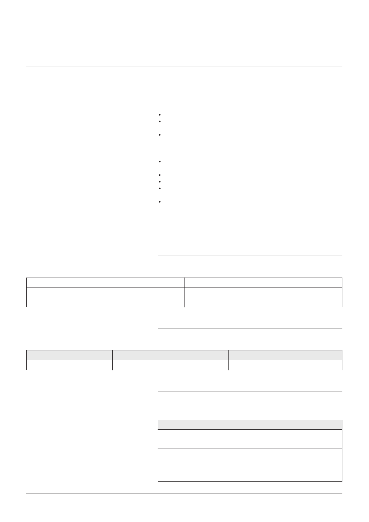
Fig.2 Installer Notification Guidelines
AD-3000696-01
Choose Building
Regulations Notification
Route
Contact your relevant Local
Authority Building Control
(LABC) who will arrange
an inspection or contact
a government approved
inspector
LABC will record the data
and will issue a
certificate of compliance
‘Gas Safe Register’ will issue a
Building Regulations Compliance
Certificate to the property owner
and inform the relevant LABC
You must ensure that the
certificate number issued by
the ‘Gas Safe Register’ is written
onto the Benchmark Checklist
Scheme Members only
Call ‘Gas Safe Register’ on:
0800 408 5577
or log onto:
www.gassaferegister.co.uk
within 10 days
If you notify via the ‘Gas Safe
Register’, the register will issue
the Building Regulations
certificate on members’ behalf
Complete the
Benchmark Checklist
Install and Commission this
appliance to manufacturer's
instructions
Competent Person's
Self Certification Scheme
Building Control
Complete the
Benchmark Checklist
Install and Commission this
appliance to manufacturer's
instructions
7661586 - 2 - 12072016 7
1 Safety
1.1.3 Installer Notification Guidelines
1 Safety
8 7661586 - 2 - 12072016
1.2 General safety instructions
Danger
This boiler can be used by children aged 8 years and above and
by persons with reduced physical, sensory or mental capabilities
or lack of experience and knowledge when they have been given
supervision or instruction concerning the safe use of the device
and understand the resulting risks. Children must not be allowed
to play with the appliance. Cleaning and user maintenance must
not be carried out by children without supervision.
Danger
If you smell gas:
1. Do not use a naked flame, do not smoke, do not operate elec
trical contacts or switches (doorbell, light, motor, lift, etc.).
2. Shut off gas supply.
3. Open the windows.
4. Trace possible leaks and seal them immediately.
5. If the gas leak is before the gas meter, contact the supplier
6. Telephone the National Gas Emergency Service on:- 0800
111 999.
Danger
If you smell flue gases:
1. Switch off the boiler.
2. Open the windows.
3. Trace possible leaks and seal them immediately.
Warning
Do not touch the flue gas pipes. Depending on the boiler settings,
o
the temperature of the flue gas pipes may exceed 60
C.
Warning
Do not touch the radiators for long periods. Depending on the boil
er settings, the temperature of the radiators may exceed 60oC.
Warning
Take precautions with the domestic hot water. Depending on the
boiler settings, the domestic hot water temperature may exceed
o
C.
65
Danger
Before any work, switch off the mains supply to the boiler.
Caution
After maintenance or repair work, check the entire heating installa
tion to ensure that there are no leaks.

1.3 Recommendations
7661586 - 2 - 12072016 9
1 Safety
Warning
Installation and maintenance of the boiler must be carried out by a
qualified installer in accordance with local and national regula
tions.
Warning
If the mains lead is damaged, it must be replaced by the original
manufacturer, the manufacturer's dealer or another suitably skilled
person to prevent hazardous situations from arising.
Warning
Always disconnect the mains supply and close the main gas tap
when working on the boiler.
Caution
Make sure the boiler can be reached at all times.
The boiler must be installed in a frost-free area.
In the case of a fixed connection to the power cord, you must al
ways install a main bipolar switch with an opening gap of at
least 3 mm (EN 60335-1).
Drain the boiler and central heating system if you are not going
to use your home for a long time and there is a chance of frost.
The frost protection does not work if the boiler is out of opera
tion.
The boiler protection only protects the boiler, not the system.
Check the water pressure in the system regularly. If the water
pressure is lower than 0.8 bar, the system must be topped up
(recommended water pressure between 1 and 2 bar).
1.4
Note
Keep this document near to the boiler.
Note
Casing panels may only be removed for maintenance and servic
ing purposes. Refit all panels when maintenance work and servic
ing are complete.
Note
Instruction and warning labels must never be removed or covered
and must be clearly legible throughout the entire service life of the
boiler. Replace damaged or illegible instruction and warning labels
immediately.
Note
The boiler must not be modified in any way.
Specific safety instructions
1.4.1 Handling
General
The following advice should be adhered to, from when first handling the
boiler to the final stages of installation, and also during maintenance.
Most injuries as a result of inappropriate handling and lifting are to the
back, but all other parts of the body are vulnerable, particularly should
ers, arms and hands. Health & Safety is the responsibility of EVERY
ONE.
There is no "safe" limit for one man - each person has different capabili
ties. The boiler should be handled and lifted by TWO PEOPLE.
Do not handle or lift unless you feel physically able.
Wear appropriate Personal Protection Equipment e.g. protective gloves,
safety footwear etc.

1 Safety
10 7661586 - 2 - 12072016
Preparation
Co-ordinate movements - know where, and when, you are both going.
Minimise the number of times needed to move the boiler - plan ahead.
Always ensure when handling or lifting the route is clear and unobstruc
ted. If possible avoid steps, wet or slippery surfaces, unlit areas etc. and
take special care on ladders/into lofts.
Technique
When handling or lifting always use safe techniques - keep your back
straight, bend your knees. Don’t twist - move your feet, avoid bending
forwards and sideways and keep the load as close to your body as pos
sible.
Where possible transport the boiler using a sack truck or other suitable
trolley.
Always grip the boiler firmly, and before lifting feel where the weight is
concentrated to establish the centre of gravity, repositioning yourself as
necessary. See the "Installation" section of these instructions for recom
mended lift points.
Remember
The circumstances of each installation are different. Always assess the
risks associated with handling and lifting according to the individual con
ditions.
If at any time when installing the boiler you feel that you may have in
jured yourself STOP !! DO NOT "work through" the pain - you may
cause further injury.
IF IN ANY DOUBT DO NO HANDLE OR LIFT THE BOILER — OBTAIN
ADVICE OR ASSISTANCE BEFORE PROCEEDING !
1.5 Liabilities
1.5.1 Manufacturer's liability
Our products are manufactured in compliance with the requirements of the
various Directives applicable. They are therefore delivered with the
marking and any documents necessary. In the interests of the quality of
our products, we strive constantly to improve them. We therefore reserve
the right to modify the specifications given in this document.
Our liability as manufacturer may not be invoked in the following cases:
Failure to abide by the instructions on installing the appliance.
Failure to abide by the instructions on using the appliance.
Faulty or insufficient maintenance of the appliance.
1.5.2 Installer's liability
The installer is responsible for the installation and initial commissioning of
the appliance. The installer must abide by the following instructions:
Read and follow the instructions given in the manuals provided with the
appliance.
Install the appliance in compliance with prevailing legislation and stand
ards.
Carry out initial commissioning and any checks necessary.
Explain the installation to the user.
If maintenance is necessary, warn the user of the obligation to check the
appliance and keep it in good working order.
Give all the instruction manuals to the user.
1.5.3 User's liability
To guarantee optimum operation of the system, you must abide by the fol
lowing instructions:
Read and follow the instructions given in the manuals provided with the
appliance.
Call on a qualified professional to carry out installation and initial com
missioning.

1 Safety
7661586 - 2 - 12072016 11
Get your installer to explain your installation to you.
Have the required inspections and maintenance carried out by a quali
fied installer.
Keep the instruction manuals in good condition close to the appliance.

2 About this manual
12 7661586 - 2 - 12072016
2 About this manual
2.1 General
This manual is intended for the installer of a Baxi Combi boiler.
2.2
2.3
Additional documentation
Symbols used
These Installation & Service Instructions must be read in conjunction with
the Flue Installation Guide supplied in the Literature Pack.
Various timers, external controls, etc. are available as optional extras. Full
details are contained in the relevant sales literature.
2.3.1
This manual uses various danger levels to draw attention to special in
structions. We do this to improve user safety, to prevent problems and to
guarantee correct operation of the appliance.
Symbols used in the manual
Danger
Risk of dangerous situations that may result in serious personal
injury.
Danger of electric shock
Risk of electric shock.
Warning
Risk of dangerous situations that may result in minor personal in
jury.
2.4
Caution
Risk of material damage.
Note
Please note: important information.
See
Reference to other manuals or pages in this manual.
Abbreviations/Glossary
Enter your glossary term here.
BS British Standard
CH Central heating
DHW Domestic hot water
GB Great Britain
HHIC Heating and Hotwater Industry Council
Hi Lower heating value (LHV)
Hs Higher heating value (HHV)
IE Ireland
PCU PCB for managing burner operation
Pn Nominal output
Pnc Condensing output
PWM Pulse wide modulation
SU Safety PCB
3 Technical specifications
7661586 - 2 - 12072016 13
3.1 Homologations
3 Technical specifications
3.1.1 Directives
Our company declares that these products are provided with the CE mark
ing in compliance with the essential requirements of the following direc
tives:
Gas Directive 2009/142/EC;
Electromagnetic Compatibility Directive 2014/30/EU General standards:
EN 61000-6-3, EN 61000-6-1 Standard in reference to: EN 55014;
Electromagnetic Compatibility Directive 2014/30/EU General standards:
EN 61000-6-3, EN 61000-6-1 Standard in reference to: EN 55014.
For appliances connected to the electricity network: Comply with the
prevailing provisions for low-voltage electrical equipment;
Low Voltage Directive 2014/35/EU General standard: EN 60335–1
Standard in reference to: EN 60335–2-102;
Efficiency Directive 92/42/EC
Ecodesign Directive 2009/125/EC;
Directive on energy consumption 2010/30/EC; Regulation (EU) No.
813/2013 and 814/2013.
Energy Labelling Directive 2010/30/EU: Regulation 811/2013 and
812/2013
In addition to the provisions and legal directives, also the complementary
directives described in these instructions must be observed. All the sup
plements and additional requirements are applicable at the moment of in
stallation.
3.1.2 Certifications
Tab.1 Certifications
CE certificate number 0085CQ0192
NOx class 5 (EN 15502)
Boiler type C13, C
33
3.1.3 Gas category
Tab.2 Gas category, type and supply pressure
Gas category Gas type Supply pressure (mbar)
I
2H
G20 20
3.1.4 Standards
Codes of Practice — refer to the most recent version
Tab.3 In GB the following Codes of Practice apply:
Standard Scope
BS 6891 Gas Installation.
BS 5546 Installation of hot water supplies for domestic purposes.
BS EN
12828
BS EN
12831
Heating systems in buildings.
Heating systems in buildings — Calculation of load.
3 Technical specifications
14 7661586 - 2 - 12072016
Standard Scope
BS EN
14336
BS 6798 Installation of gas fired hot water boilers.
BS 5440
Part 1
BS 5440
Part 2
BS 7074 Expansion vessels and ancillary equipment for sealed wa
BS 7593 Treatment of water in domestic hot water central heating
BS 4814 Specification for Expansion Vessels using an internal dia
IGE/UP/
7/1998
Tab.4 In IE the following Code of Practice apply:
Standard Scope
IS 813 Domestic Gas Installations.
The following standards give valuable additional information:
BS 5546 Installation of hot water supplies for domestic purposes.
BS EN
12828
BS EN
12831
BS EN
14336
BS 7074 Expansion vessels and ancillary equipment for sealed wa
BS 7593 Treatment of water in domestic hot water central heating
Installation & commissioning of water based heating sys
tems.
Flues.
Ventilation.
ter systems.
systems.
phragm, for sealed hot water systems.
Guide for gas installations in timber framed housing.
Heating systems in buildings.
Heating systems in buildings — Calculation of load.
Installation & commissioning of water based heating sys
tems.
ter systems.
systems.
3.2 Technical data
3.2.1 Technical information
Note
All data in these sections are nominal and subject to normal pro
duction tolerances.
Tab.5 General
Baxi Combi 224 228 424 428
Gas Council Numbers 47–077–21 47–077–22 47–077–23 47–077–24
Nominal heat input Domes
tic Hot Water — Maximum
Rate
Nominal Heat Input Central
Heating — Maximum Rate
Nett (Qn
Hi)
Gross
(Qn Hs)
Nett (Qn
Hi)
Gross
(Qn Hs)
kW 24.7 28.9 24.7 28.9
kW 27.4 32.1 27.4 32.1
kW 20.6 24.7 20.6 24.7
kW 22.9 27.4 22.9 27.4

3 Technical specifications
7661586 - 2 - 12072016 15
Baxi Combi 224 228 424 428
Nominal Heat Input — Min
imum Rate
Nett (Qn
Hi)
Gross
kW 4.9 4.9 4.9 4.9
kW 5.4 5.4 5.4 5.4
(Qn Hs)
Nominal heat output
Pn kW 24.0 28.0 24.0 28.0
80/60°C — Domestic Hot
Water — Maximum Rate
Nominal heat output
Pn kW 20.0 24.0 20.0 24.0
80/60°C — Central Heating
— Maximum Rate
Nominal heat output
Pn kW 20.0 20.0 20.0 20.0
80/60°C — Central Heating
— Factory Setting
Nominal heat output
Pn kW 4.8 4.8 4.8 4.8
80/60°C — Minimum Rate
Nominal heat output
Pnc kW 21.8 26.1 21.8 26.1
50/30°C — Central Heating
— Maximum Rate
Nominal heat output
Pnc kW 5.2 5.2 5.2 5.2
50/30°C — Central Heating
— Minimum Rate
Tab.6 Central heating circuit specifications
Baxi Combi 224 228 424 428
Maximum pressure bar 3 3 3 3
Minimum pressure bar 0.5 0.5 0.5 0.5
Central heating temperature adjust
°C 25/80 25/80 25/80 25/80
ment ±5°C
Expansion vessel water capacity litres 7.0 7.0 7.0 7.0
Expansion vessel pre charge pres
bar 1.0 1.0 1.0 1.0
sure
Maximum capacity of central heat
litres 120 120 120 120
ing system
Primary water content of boiler (un
litres 2.5 2.5 2.5 2.5
pressurised)
Tab.7 Domestic hot water circuit specifications
Baxi Combi 224 228 424 428
Maximum pressure bar 8.0 8.0 8.0 8.0
Dynamic minimum pressure bar 0.5 0.5 0.5 0.5
Minimum working water flow rate l/min 2.0 2.0 2.0 2.0
Specific flow rate (D) l/min 11.5 13.4 11.5 13.4
Domestic hot water temperature
°C 35/60 35/60 35/60 35/60
range adjustment ±5°C
Production of domestic water with
l/min 13.8 16.1 13.8 16.1
ΔT = 25°C
Production of domestic water with
l/min 9.8 11.5 9.8 11.5
ΔT = 35°C
Where low flow taps or fittings are intended to be used in the DHW system connected to the boiler, it is strongly recommended
that the DHW flow rate DOES NOT fall below 2.5 l/min. This will ensure reliable operation of the DHW function.

3 Technical specifications
16 7661586 - 2 - 12072016
Tab.8 Characteristics of combustion
Baxi Combi 224 228 424 428
Natural gas rate (G20) Qmax
Natural gas rate (G20) Qmin
Diameter of coaxial discharge
m3/h
m3/h
mm 60/100 & 80/125 60/100 & 80/125 60/100 & 80/125 60/100 & 80/125
2.61 3.06 2.61 3.06
0.52 0.52 0.52 0.52
pipes
Note
Dynamic (nominal) inlet pressure (Natural gas — G20) 20mbar
with a CV of 37.78 MJ/m
3
Tab.9 Electrical specifications
Baxi Combi 224 228 424 428
Nominal electrical power supply
V 230 230 230 230
voltage
Nominal electrical power supply
Hz 50 50 50 50
frequency
Nominal power consumption when
W 84 94 84 94
firing
External fuse rating Amp 3 3 3 3
F2 Internal fuse rating — Connec
Amp 0.5 0.5 0.5 0.5
tion board ’B’
F1 Internal fuse rating — Main PCB
Amp 1.6 1.6 1.6 1.6
board ‘A’
Note
Boiler must be connected to an earth supply.
Tab.10 Other specifications
Baxi Combi 224 228 424 428
Degree of protection against hu
IP IPX5D IPX5D IPX5D IPX5D
midity (EN 60529) without plug-in
timer / receiver fitted
Degree of protection against hu
IP IPXO IPXO IPXO IPXO
midity (EN 60529) with plug-in tim
er / receiver fitted
Dimensions (height/width/depth) mm 700/395/279 700/395/279 700/395/279 700/395/279
Tab.11 Connections (copper tails)
Baxi Combi 224 228 424 428
Gas inlet mm 22 22 22 22
Heating flow mm 22 22 22 22
Heating return mm 22 22 22 22
Cold water inlet mm 15 15 15 15
Hot water outlet mm 15 15 15 15
Pressure relief discharge mm 15 15 15 15
Condensate discharge drain plastic
mm 21.5 21.5 21.5 21.5
waste pipe

3 Technical specifications
7661586 - 2 - 12072016 17
Tab.12 Clearances
Baxi Combi 224 228 424 428
Above casing mm 178 178 178 178
Below casing (min)
Below casing (recommended)
Front — for servicing (min)
Front — for servicing (recommen
mmmm200
250
mmmm450
1000
200
250
450
1000
200
250
450
1000
200
250
450
1000
ded)
Front — for operation mm 6 6 6 6
Sides LH mm 5 5 5 5
Sides RH mm 5 5 5 5
Tab.13 Weights
Baxi Combi 224 228 424 428
Packaged boiler kg 30.0 30.0 30.5 30.5
Boiler lift weight (dry) kg 26.0 26.0 26.0 26.0
Installed weight (dry) kg 28.0 28.0 28.5 28.5
Installed weight when filled with wa
kg 30.5 30.5 31.0 31.0
ter
3.2.2 Technical parameters
Tab.14 Technical parameters for boiler combination heaters
Baxi Combi 224 228 424 428
Condensing boiler Yes Yes Yes Yes
Low-temperature boiler
(1)
B1 boiler No No No No
Cogeneration space heater No No No No
Combination heater Yes Yes Yes Yes
Rated heat output
Useful heat output at rated heat output
and high temperature regime
(2)
Useful heat output at 30% of rated heat
output and low temperature regime
Seasonal space heating energy efficiency
Useful efficiency at rated heat output and
high temperature regime
Useful efficiency at 30% of rated heat
output and low temperature regime
Auxiliary electricity consumption
Full load
Part load
Standby mode
Other items
Standby heat loss
Ignition burner power consumption
Annual energy consumption
No No No No
Prated
P
4
P
1
ƞ
s
ƞ
4
ƞ
1
elmax
elmin
P
SB
P
stby
P
ign
Q
HE
kW 20 24 20 24
kW 20.0 24.0 20.0 24.0
kW 6.7 8.0 6.7 8.0
% 93 93 93 93
% 88.1 88.0 88.1 88.0
% 97.8 97.8 97.8 97.8
kW 0.028 0.038 0.028 0.038
kW 0.011 0.011 0.011 0.011
kW 0.003 0.003 0.003 0.003
kW 0.069 0.069 0.069 0.069
kW 0.000 0.000 0.000 0.000
GJ 62 74 62 74

1
2
3
4
5 6 7
8
700
279
395
PN-0000264
A
*
5.0
6
B*
285
700
3
95
PN-0000205
5.0
178
3 Technical specifications
18 7661586 - 2 - 12072016
Baxi Combi 224 228 424 428
Sound power level, indoors
Emissions of nitrogen oxides NO
L
WA
X
dB 48 50 48 50
mg/kWh 38 40 38 40
Domestic hot water parameters
Declared load profile XL XL XL XL
Daily electricity consumption
Annual electricity consumption
Water heating energy efficiency
Daily fuel consumption
Annual fuel consumption
(1) Low temperature means for condensing boilers 30°C, for low temperature boilers 37°C and for other heaters 50°C return temperature (at
heater inlet).
(2) High temperature regime means 60°C return temperature at heater inlet and 80°C feed temperature at heater outlet.
Q
elec
AEC
ƞ
wh
Q
fuel
AFC
kWh 0.151 0.151 0.151 0.151
kWh 33 33 33 33
% 86 85 86 85
kWh 22.770 22.930 22.770 22.939
GJ 17 17 17 17
See
The back cover for contact details.
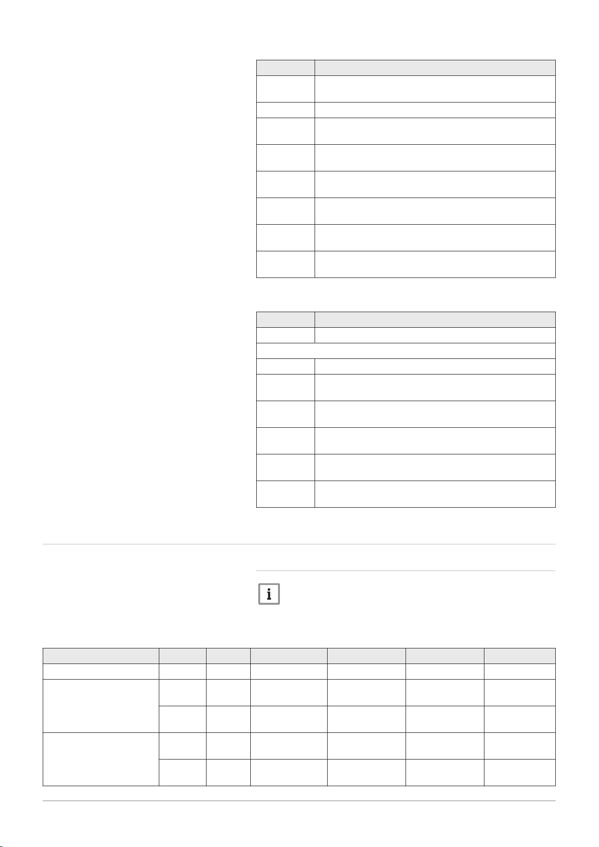
3.3
Fig.3
Fig.4
Dimensions and connections/clearances
Dimensions and connections
Clearances
1
2
3
4
5
6
7
8
Safety valve
Heating circuit water flow
Condensate discharge
Heating system/boiler drain tap
Domestic hot water outlet
Gas inlet
Mains cold water inlet
Heating circuit water return
The clearances shown in the diagram are minimum requirements to allow
for case removal, spanner access and air movement. These should be ob
served at all times and kept clear of obstructions.
A* Clearance below boiler— Minimum 200mm, Recommended
250mm
B* Clearance in front of boiler— Minimum 450mm, Recommended
1000mm

Fig.5 Paper template
Ø 8
34 33.5 65 65 65 65 67.5
198 198
50 MIN
82.5
32
116 Dia Minimum
Aperture For
Flue Tube
Vertical Flue
Centre Line
Ø 22
Heating
Return
(22mm)
Heating
Flow
(22mm)
Hot Water
Outlet
(15mm)
Combi Only
Not System
Cold Water
Inlet
(15mm)
Combi Only
Not System
Side Clearance 5Side Clearance 5
Clearance below 250
Clearance above 178
Wall
View from under boiler
PN-0000223
7661586 - 2 - 12072016 19
3 Technical specifications

HMI
1
1
1
GND
1
1
PWM - P
L-BUS
E
1
1
1
L
N
G/Y
G/Y
W
Br
Bl
DV
PN-0000268
Bl
Br
Bl
Br
P
230V - 50Hz
Gy
R
W
Bk
Vt
Br
Bl
13
R
R
R
R
Gn
W
Br
R Bl Gn
Br
Bl
Y
Bk
Bk
R
R
Vt
Vt
Vt
Vt
Br
Br
Br
Br
R R
Bk
Bk
W
Br
123 4 5 123 4 5 67
1
2 1
123
Br
Br
Bl
Bk
Bk
Gy
Bl
W
Gy
Vt
Br
BkWGn
Br
R
Bl
R
L-BUS
Bk
R
W
Gn
Gn
Wk
Bk
Br
R
16
F1
F1 (1,6A)
L
N
L(CH)
L(DW)
N
GV
W8-1
W8-2
W8-4
W8-3
ST
HS
WPS
DS RS
FS
X6-A
X9-1
X14-A
X4-A
W8
X5-A
X1-A
X3-A
X2-A
A
JP1
G/Y
G/Y
Circuit Board
‘A’
Connection Board
‘B’
SERVICE
X7 X6
F2
0.5A
X14
OS
X13
J
X9
L-BUS
3
On
B
X12
X11 X10
X3
TIMER
X2
X5
Off
230V - 50Hz
LN
2
1
X1 MAINS
X4
RT
X8
OT
Gn
Bk
Br Brown
Bl Blue
Bk Black
G/Y Green/Yellow
R Red
Gn Green
Gy Grey
W White
Vt Violet
Mains 230V
W4
W3
+
C2
C1
SIG
W2
W1
W5
F
3 Technical specifications
20 7661586 - 2 - 12072016
3.4 Electrical diagram
Fig.6 Electrical diagram

Tab.15 Electrical connections inside the boiler (A)
7661586 - 2 - 12072016 21
Electrical power supply 230 V — 50 Hz
X1–A
1: Earthing connector
2: L (230 V)
3: N
Pump
X2–A
1: Earth connection
2: L (230 V)
3: N
3-way valve
X3–A
1: L (CH) 230 V — Heating circuit opening command
2: L (DW) 230 V — Domestic water circuit opening command
3: N — Common
X4–A Pump PWM signal
Sensor connection
HS: domestic water request
RS: heating circuit water return
X5–A
DS: heating circuit water flow
FS: flue gas
WPS: hydraulic pressure switch
ST: safety thermostat
X6–A Boiler PCB and control panel connection (electrical connection board)
X13–A Not used
X14–A Connection L-BUS
3 Technical specifications
Tab.16 Electrical connections to be made to the boiler (B)
Electrical power supply 230 V — 50 Hz
X1–B
1: N
2: L (230 V)
3: Earthing connector
X4–B Room thermostat/timer (230V)
X6–B Not used
X7–B Solar probe connection
X8–B On-Off/R-Bus - Room thermostat connection (the jumper must be REMOVED to connect a device)
X9–B Service connection (SERVICE)
X13–B Connection L-BUS
X14–B Outside sensor connection (OS)
Dip-Switch
J
1: Maximum heating temperature OFF = 80°C - ON = 45°C (floor system)
2: OFF = Maximum output (heating) - ON = Boiler output 50% (heating)
3: DO NOT ADJUST

4 Description of the product
22 7661586 - 2 - 12072016
4 Description of the product
4.1 General description
The Baxi Combi condensing boiler is a gas-fuelled boiler. The purpose of
this boiler is to heat water to a temperature that is lower than boiling point
at atmospheric pressure. It must be connected to a heating installation and
to a domestic hot water distribution system that is compatible with its pow
er and performance ratings. Features of this boiler:
Low pollutant emissions.
High-efficiency heating.
Combustion products discharged through a coaxial connector.
Front control panel with display.
Lightweight and compact.
4.2
Operating principle
4.2.1
The air is drawn in by the fan and gas injected directly at the top of the
mixer valve. The fan rotation speed is regulated automatically by the elec
tronic board based on temperature adjustment and other parameters. The
gas and air are mixed in the manifold. The gas/air ratio ensures that the
quantity of gas and air are adjusted correctly to always obtain optimal
combustion. The gas/air mixture is fed into the burner at the front of the
heat exchanger. The mixture is ignited by the spark electrode.
Air-gas adjustment
4.2.2 Combustion
The burner heats the heating water circulating in the heat exchanger.
When the temperature of the combustion gas is lower than the dew point
(around 55 °C), the water vapour contained in the combustion gas con
denses in the flue gas side of the heat exchanger. The heat recovered
during this condensation process (the latent heat or condensing heat) is
also transferred to the heating water. Once cooled, the combustion gases
are discharged through the flue exhaust. The condensed water is dis
charged through a trap.

4.3 Main components
1
3
2
4
5
6
7
8
9
10
12
13
11
21
22
23
25
26
24
28
27
15
16
17181920
14
PN-0000286
PN-0000266
PN-0000267
7661586 - 2 - 12072016 23
4 Description of the product
4.2.3 Heating and domestic hot water production
Fig.7
Component description
1 Boiler case
2 Mounting slots for wall bracket
3 Flue adaptor
4 Expansion vessel air control/filling valve
5 Expansion vessel
6 Burner door
7 Detection/ignition electrode
8 Water circuit-expansion vessel connection pipe
9 Air-gas assembly (control board, fan, mixer valve)
10 Automatic air vent
11 Gas valve
12 Pump
13 3-way valve
14 Pressure gauge (fitted on the panel)
15 Domestic hot water priority sensor
16 Boiler electrical connection board
17 Domestic hot water plate heat exchanger fastening screws
18 Domestic hot water plate heat exchanger
19 Pressure relief valve
20 Condensate trap
21 Hydraulic pressure sensor
22 Silencer
23 Trap quick connection (with gaskets)
24 Heating circuit water flow sensor
25 Overheat safety thermostat
26 Heating circuit water return sensor (behind the silencer)
27 Heat exchanger
28 Flue gas temperature sensor
4.4 Control panel description
Fig.8 Control panel
Fig.9 Display screen
4.4.1 Description of the keys
Heating temperature control knob
Level access button: Information, Installer or Chimney Sweep
Manual reset button
4.4.2 Description of the display
Domestic hot water temperature control knob
Hour run meter
Malfunction
Maintenance
Reset necessary
Burner status
Heating mode
Outside temperature sensor
Domestic hot water mode

4 Description of the product
24 7661586 - 2 - 12072016
4.5 Standard delivery
4.5.1 Contents of the carton
The boiler is delivered in a carton comprising:
a wall-hung gas boiler;
a bracket for fastening the boiler to the wall;
a paper template;
an installation and service manual;
a user manual.
a fitting kit, including taps and tail pipes.
4.6
Accessories and options
4.6.1 Optional accessories
The table below shows the accessories available for this boiler range.
Tab.17 Optional accessories
Part number Accessory
7658276 Baxi plug-in 24 hr mechanical timer combi - RH
7658523 Baxi plug-in 7 day digital timer combi - RH
7658781 Baxi plug-in receiver 24 hr RF programmable mech room
thermostat-combi
7658789 Baxi plug-in receiver 7 day RF digital programmable room
thermostat-combi
7212438 Baxi single channel wired programmable room thermostat
7212444 Baxi single channel wired timer
720971601 Baxi room thermostat
720330001 Baxi wired weather sensor
720648301 Multifit condensate & PRV combined pump
720644401 Multifit 1m condensate drain pipe 'trace heating' element
720664101 Multifit 2m Condensate drain pipe 'trace heating' element
720664201 Multifit 3m condensate drain pipe 'trace Heating' element
720664401 Multifit 5m condensate drain pipe 'trace heating' element
7659335 Baxi 200-400 stand off kit
5121379 Multifit remote secondary PRV kit
248221 Multifit filling loop (Not required for 424 and 428 models)
For Flue Accessories (elbows, extensions, clamps etc.) refer to the Flue
Installation Guide supplied in the literature pack.
Any of the above MUST be fitted ONLY by a qualified competent person.
Further details can be found in the relevant sales literature and at
www.baxi.co.uk
 Loading...