

Baxi 100 HE
Wall Mounted Powered Flue Condensing Boiler
Gas Fired Central Heating Unit
Installation and
Servicing Instructions
Please leave these instructions with the user

2
Baxi UK Limited is one of the leading manufacturers
of domestic heating products in the UK.
Our first priority is to give a high quality service to our
customers. Quality is designed into every Baxi product
- products which fulfil the demands and needs of
customers, offering choice, efficiency and reliability.
To keep ahead of changing trends, we have made a
commitment to develop new ideas using the
latest technology - with the aim of continuing to make
the products that customers want to buy.
Everyone who works at Baxi has a commitment to
quality because we know that satisfied customers
mean continued success.
We hope you get a satisfactory service from Baxi. If
not, please let us know.
Natural Gas
Baxi 100 HE
G.C.No41 075 32
Baxi is a BS-EN ISO 9001
Accredited Company
The boiler meets the requirements of Statutory Instrument
“ The Boiler (Efficiency) Regulations 1993 N
o
3083” and is
deemed to meet the requirements of Directive 92/42/EEC
on the energy efficiency requirements for new hot water
boilers fired with liquid or gaseous fuels:-
Type test for purpose of Regulation 5 certified by:
Notified Body 0086.
Product/Production certified by:
Notified Body 0086.
For GB/IE only.
3
1.0 Introduction 4
2.0 General Layout 5
3.0 Appliance Operation 6
4.0 Technical Data 7
5.0 Dimensions and Fixings 8
6.0 System Details 9
7.0 Site Requirements 12
8.0 Installation 17
9.0 Electrical 23
10.0 Commissioning the Boiler 25
11.0 Fitting the Outer Case 26
12.0 Servicing the Boiler 27
13.0 Changing Components 29
14.0 Fault Finding 36
15.0 Short Parts List 44
Section Page
Contents
Baxi UK Limited declare that no substances
harmful to health are contained in the appliance
or used during appliance manufacture.
NOTE: This appliance must be installed in
accordance with the manufacturer’s instructions
and the regulations in force, and only used in a
suitably ventilated location.
All systems must be thoroughly flushed and
treated with inhibitor (see Section 6.2).
Read the instructions fully before installing or
using the appliance.
1.1 Description
1. The Baxi 100 HE is a gas fired room sealed fan
assisted condensing central heating boiler.
2. The maximum output of the boiler is preset at
75,000 Btu/hr. The boiler will automatically adjust
down to 30,000 Btu/hr according to the system
load. If required, the output can be set to 100,000
Btu/hr. Please refer to section 8.8.
3. It is designed for use on Natural Gas (G20).
4. The boiler is suitable for fully pumped open
vented central heating and domestic hot water
systems and sealed systems.
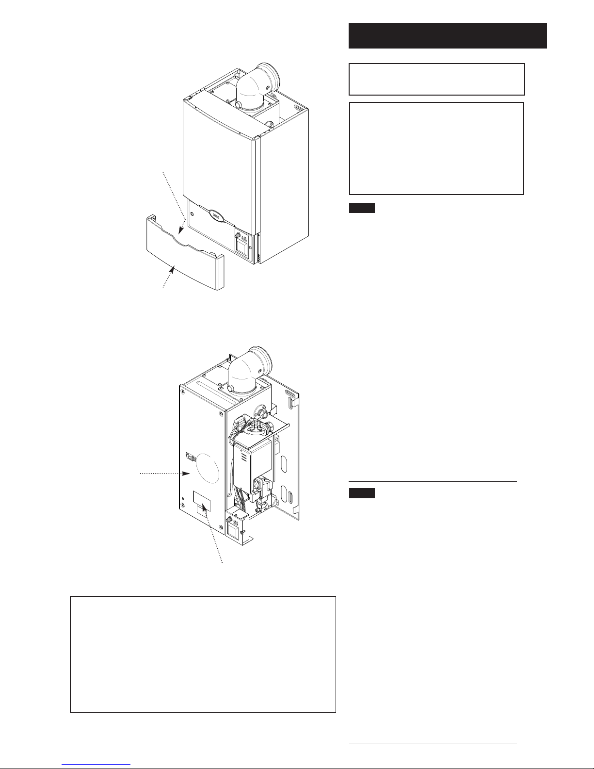
5. A label giving details of the model, serial number
and Gas Council number is situated on the rear of
the lower door panel (Fig. 1).
6. The boiler data badge is positioned on the air
box door (Fig. 2).
7. The boiler is intended to be installed in
residential / commercial / light industrial E.M.C.
environments on a governed meter supply only.
8. The boiler must be installed with one of the
purpose designed flues such as the standard
horizontal flue kit, part n
o
236921.
1.2 Important Information
This product contains Refractory Ceramic Fibres
(R.C.F.) which are man-made vitreous silicate fibres.
Excessive exposure to these materials may cause
temporary irritation to eyes, skin and respiratory tract.
Care must be taken when handling these articles to
ensure the release of dust or fibres is kept to a
minimum.
To ensure that the release of fibres from these articles
is kept to a minimum, during installation and servicing
it is recommended that a H.E.P.A. filtered vacuum is
used to remove any dust, soot or other debris
accumulated in and around the appliance. This should
be performed before and after working on the
installation.
It is recommended that any replaced item(s) are not
broken up but sealed within heavy duty polythene
bags and clearly labelled “R.C.F. waste”. This is not
classified as “hazardous waste” and may be disposed
of at a tipping site licensed for the disposal of
industrial waste.
Protective clothing is not required when handling
these articles but it is recommended that gloves are
worn and the normal hygiene rules of not smoking,
eating or drinking in the work area are followed and
always wash hands before eating or drinking.
1.0 Introduction
4
Fig. 1
H
IG
H
L
O
W
H
I
G
H
L
O
W
Data Badge
Air Box Door
Lower Door Panel
Position of Label
Fig. 2
“Benchmark” Log Book
As part of the industry-wide “Benchmark” initiative all Baxi boilers now
include an Installation, Commissioning and Service Record Log Book.
Please read the Log Book carefully and complete all sections relevant to
the appliance and installation. These include sections on the type of
controls employed, flushing the system, burner operating pressure etc.
The details of the Log Book will be required in the event of any warranty
work. Also, there is a section to be completed at each subsequent regular
sevice visit.
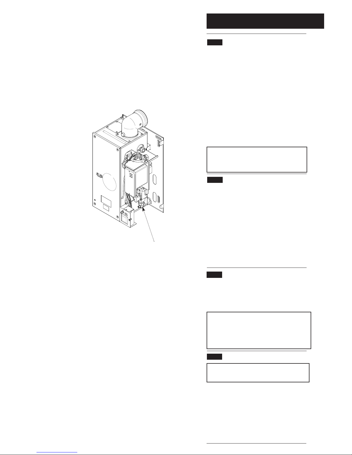
2.0 General Layout
5
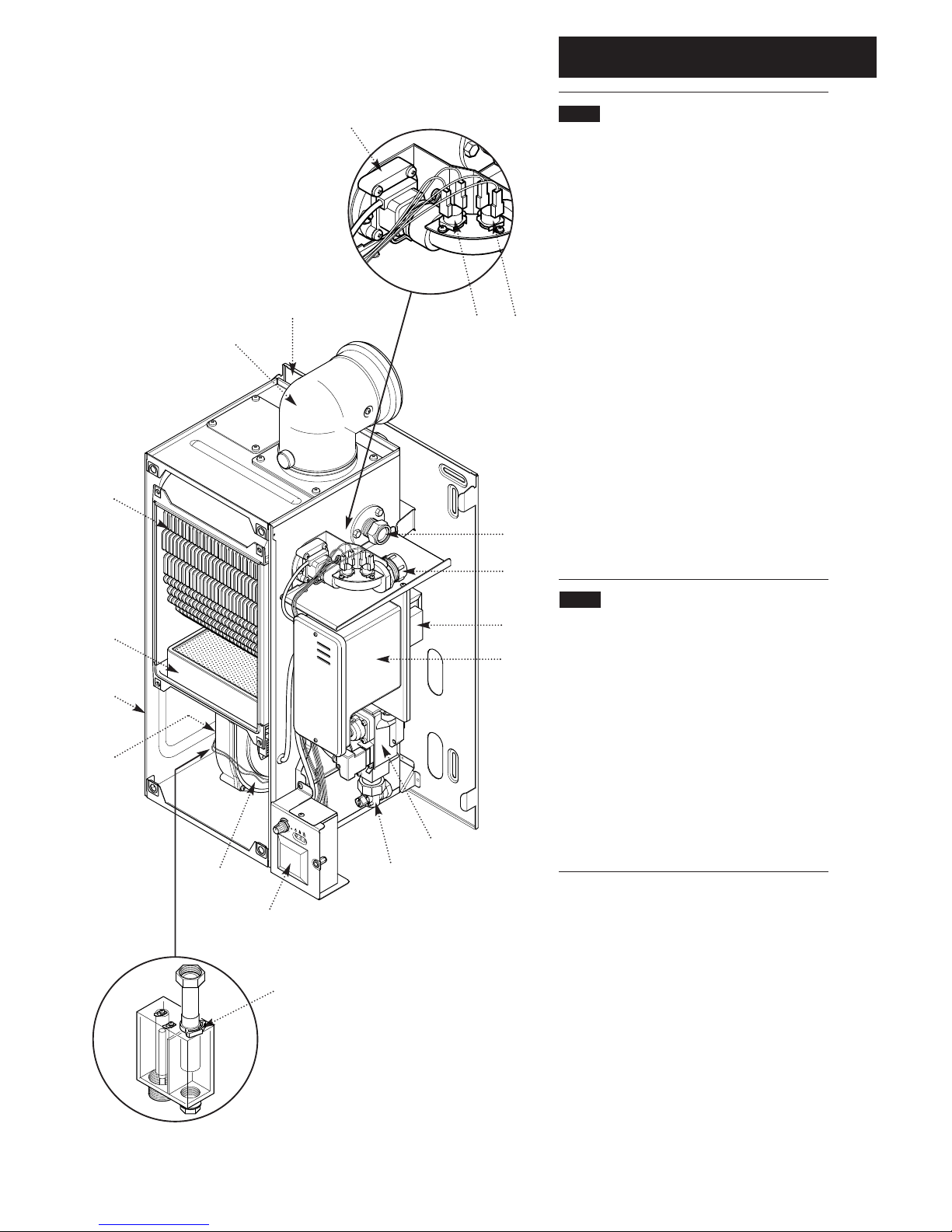
2.1 Layout (Figs. 3,4 & 5)
1. Wall Plate
2. Flue Elbow
3. Heat Exchanger
4. Burner
5. Air Box
6. Fan Protection Thermostat
7. Fan Assembly
8. Condensate Trap
9. User Interface (optional timer available)
10. Gas Tap
11. Gas / Air Ratio Valve
12. Electronics Housing
13. Transformer
14. Flow Pipe Connection
15. Return Pipe Connection
16. Flow Temperature Safety Thermostat - Black
17. Flow Temperature Thermistor - Red
18. Flow Switch (dry fire protection)
H
I
G
H
L
O
W
1
2
3
4
5
6
7
9
8
10
11
12
13
17 16
14
15
18
Fig. 4
Fig. 3
Fig. 5
2.2 Optional Extras
KIT PART N
o
FLUE EXTENSION KITS (110/70)
Flue Extension 0.25M 241692
Flue Extension 0.5M 241694
Flue Extension 1M
(Use two kits for 2M etc.) 241695
Flue Bend x 2 - 45°
(Reduce overall length of flue
by 0.5m when fitting this bend)
241689
Flue Bend - 90° (
Reduce overall length of flue
by 1m when fitting each bend)
241687
VERTICAL FLUE (110/70)
Vertical Flue Terminal 242802
Vertical Boiler Connection 242886
CONTROL ACCESSORIES
Integral Electronic Twin Channel Timer Kit 242834
3.0 Appliance Operation
6
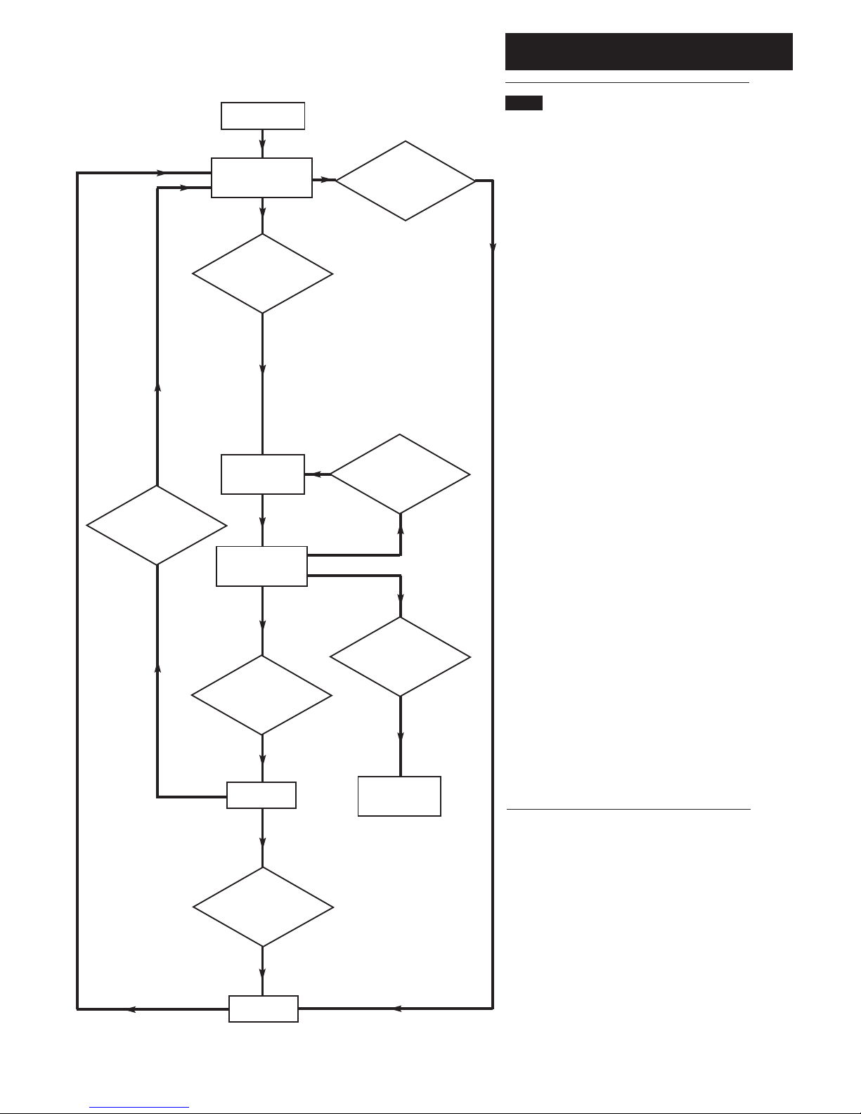
3.1
1. Switched Live On: When the switched live
switches on pump overrun occurs.
2. Pump Overrun: The pump is on while the fan,
spark generator and gas valve are off. If at any
stage during pump overrun the flow temperature
is less than the set point and the flow switch is
made then fan purge occurs. After 1 minute of
pump overrun anti-cycle occurs.
3. Fan Purge: The pump and fan are on while
the spark generator and gas valve are off. After 5
seconds ignition occurs.
4. Ignition: The pump, fan, spark generator and
gas valve are on. If a flame is detected then
burner on occurs. If a flame is not detected within
5 seconds and less than 5 ignition attempts have
been made then fan purge occurs. If a flame is
not detected within 5 seconds and 5 ignition
attempts have been made the ignition lockout
occurs.
5. Burner On: The pump, fan and gas valve are
on while the spark generator is off. Flow
temperature is controlled by varying the fan
speed (and thereby the gas rate) to achieve
optimum operation. If the flow temperature is
greater than the set point then pump overrun
occurs. If the TRVs all shut down then anti-cycle
occurs.
6. Anti-cycle: The pump, fan, spark generator
and gas valve are switched off. After 3 minutes
pump overrun occurs.
7. Ignition Lockout: The pump, fan, spark
generator and gas valve are switched off. The
boiler can only be reset by manually using the
thermostat knob.
Mains On.
Flow
temperature less
than set point and flow
switch made ?
YES
5 second
Fan Purge.
Flame Detected ?
Burner On.
Ignition
Lockout.
5 second
Ignition Period.
All TRVs
shut down ?
Flow temperature
greater than set
point ?
Ignition done and
5 attempts made ?
Ignition done
and less than 5
attempts made ?
Pump Overrun
Anti-cycle.
Pump Overrun
for 1 minute ?
YES
YES
YES
YES
YES
YES
Appliance Category CAT I
2H
4.0 Technical Data
7
Horizontal
Flue Terminal Diameter 110mm
Dimensions Projection 150mm
Outercase Dimensions
Overall Height Inc Flue Elbow - 750mm
Casing Height - 600mm
Casing Width - 390mm
Casing Depth - 320mm
Weights kg lb
Packaged Boiler Carton 40.7 89.6
Packaged Flue Kit 3.6 8.0
Weight Empty 38.2 84.1
Installation Lift Weight 31.5 69.3
Connections
Gas Supply -1/2in BSPT
Central Heating Flow - 28mm
Central Heating Return - 28mm
Condensate Drain - 1 in BSP
Recommended System
Temperature Drop
Normal 11°C20°F
Condensing 20°C36°F
Heat Input Max Min
(see note) kW 33.76 10.2
Btu/h 115,200 34,840
Heat Output
(Non Condensing 70° C Mean Water Temp)
Max Min
kW 30.18 9.14
Btu/h 102,980 31,180
Electrical Supply 230V~ 50Hz
(Appliance must be connected to an
earthed supply)
Power Consumption 80W
External Fuse Rating 3A
Internal Fuse Rating (BS 4265)
Fuse (2) 4 AT (Control Board)
Fuse (3) 2 AT (Ignition Board)
Max Gas Rate (Natural Gas)
(After 10 Mins)
Btu/hr 102,980 75,000
m3/h 2.95 2.31
ft3/h 104.2 81.6
Inlet Pressure at Gas Valve (Natural Gas)
Min 18.1 mbar
Max 22.5 mbar
(see Section 10.1)
Injector (Natural Gas)
6.3mm Diameter
Clearances
(For unventilated compartments see Section 7.5)
Both Sides 5mm Min
Above Casing 200mm Min
Below Casing 50mm Min
Front (For Servicing) 500mm Min
Front (In Operation) 5mm Min
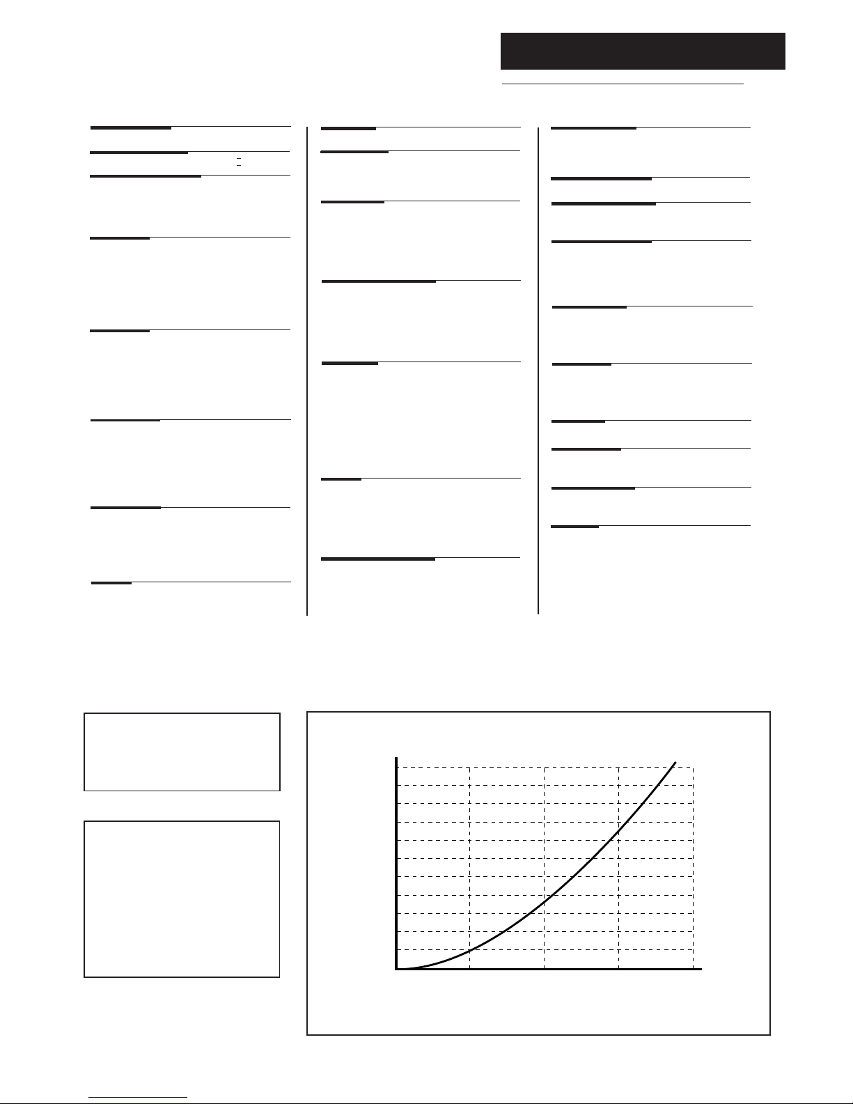
0 10203040
20
40
60
80
100
120
140
160
180
200
220
Water Flow Rate (litres/min)
Pressure Drop (mbar)
0.8
1.7
2.5
3.3
4.2
5.0
5.8
6.6
7.5
8.3
9.1
Pressure Drop (in wg)
Hydraulic Resistance Chart
Appliance Type C
13
C
33
Nox Class 5
Heat Output
(Condensing 40° C Mean Water Temp)
Max Min
kW 32.61 10.1
Btu/h 111,280 34,520
Water Content
litres 2.6
pints 4.6
Static Head
max 30 metres (100 ft)
min 1 metre (3.25 ft)
Low Head 0.2m (8 in) min
System Detail
fully pumped open vented & sealed systems
Gas Connection
RC1/2(1/2in BSPT)
Controls
boiler thermostat, safety thermostat,
flow switch, electronic flame sensing,
temperature protection thermostat &
condensate blockage sensor
NOTE: The maximum output of the
boiler is factory set at 22.0kW
(75,000 Btu/hr). This can be altered
to 30.18kW (102,980 Btu/hr)
- see section 8.8.
The efficiency is 90.9%
This value is used in the UK Government’s
Standard Assessment Procedure (SAP) for
energy rating of dwellings. The test data from
which it has been calculated has been
certified by 0086.
SEDBUK Declaration For 100 HE
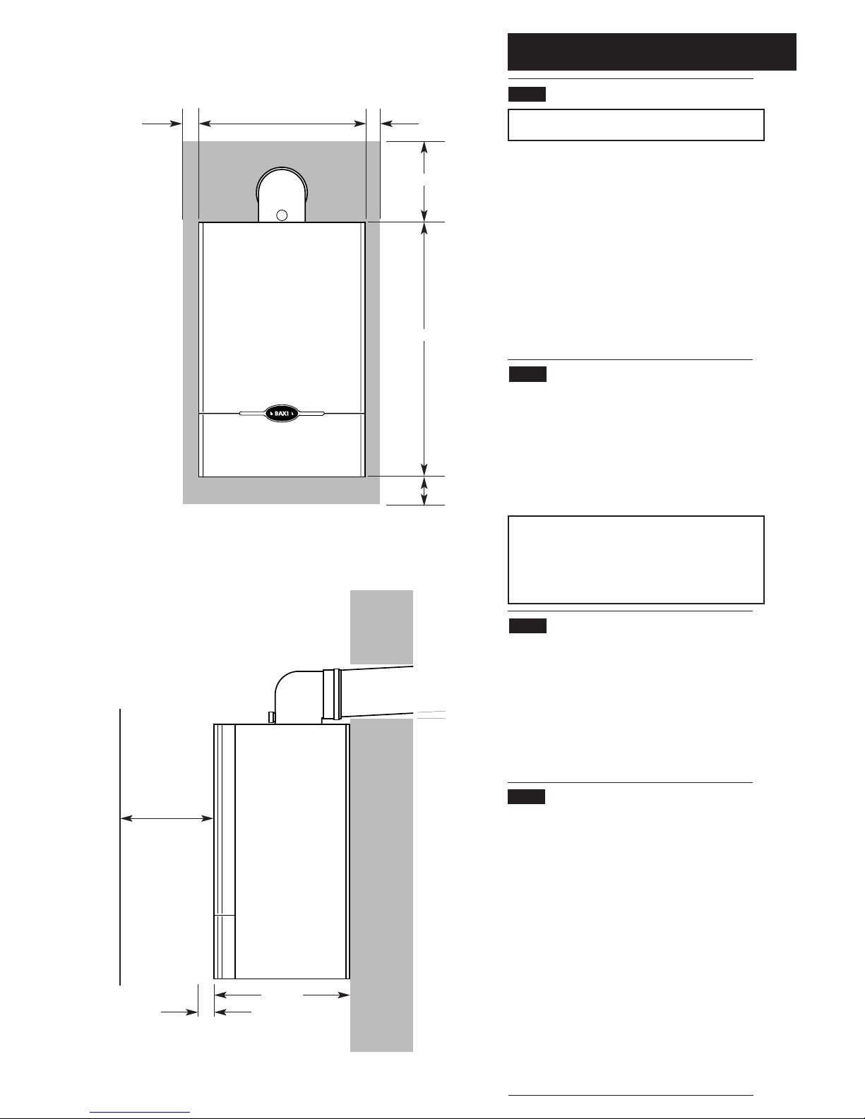
5.0 Dimensions and Fixings
8
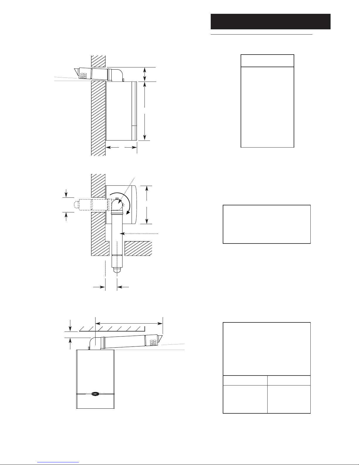
DIMENSIONS
A 600mm
B 320mm
C 390mm
D 125mm Ø Min.
E 150mm
F 125mm
SIDE FLUE (left and right)
For every 1m of horizontal flue
length, the clearance above the
top of the flue elbow should be
55mm to incorporate the 3°
(1 in 20) fall in the flue from the
terminal to the elbow.
The 3° (1 in 20) fall provided by
the elbow is to allow condensate
to run back to the boiler, for
disposal through the condensate
discharge pipe.
Flue length (Y)
up to 1m
1m - 2m
2m - 3m
Clearance (X)
55mm
110mm
165mm
360° Orientation
Tube Ø 110mm
D
C
B
A
E
F
Y
3°
(1 in 20)
X
3°
(1 in 20)
Fig. 6
Fig. 7
6.0 System Details
9
6.1 Water Circulating Systems
1. The appliance is suitable for use with open vent
fully pumped systems and sealed systems .
The following conditions should be observed
on all systems:
• The static head must not exceed 30m (100ft)
of water.
• The boiler must not be used with a direct
cylinder.
• Drain cocks should be fitted to all system low
points.
• All gas and water pipes and electrical wiring
must be installed in a way which would not
restrict the servicing of the boiler.
• Position isolating valves as close to circulating
pump as possible.
• It is recommended that the return pipe is fitted
with an automatic air vent as close to the boiler
as is practical.
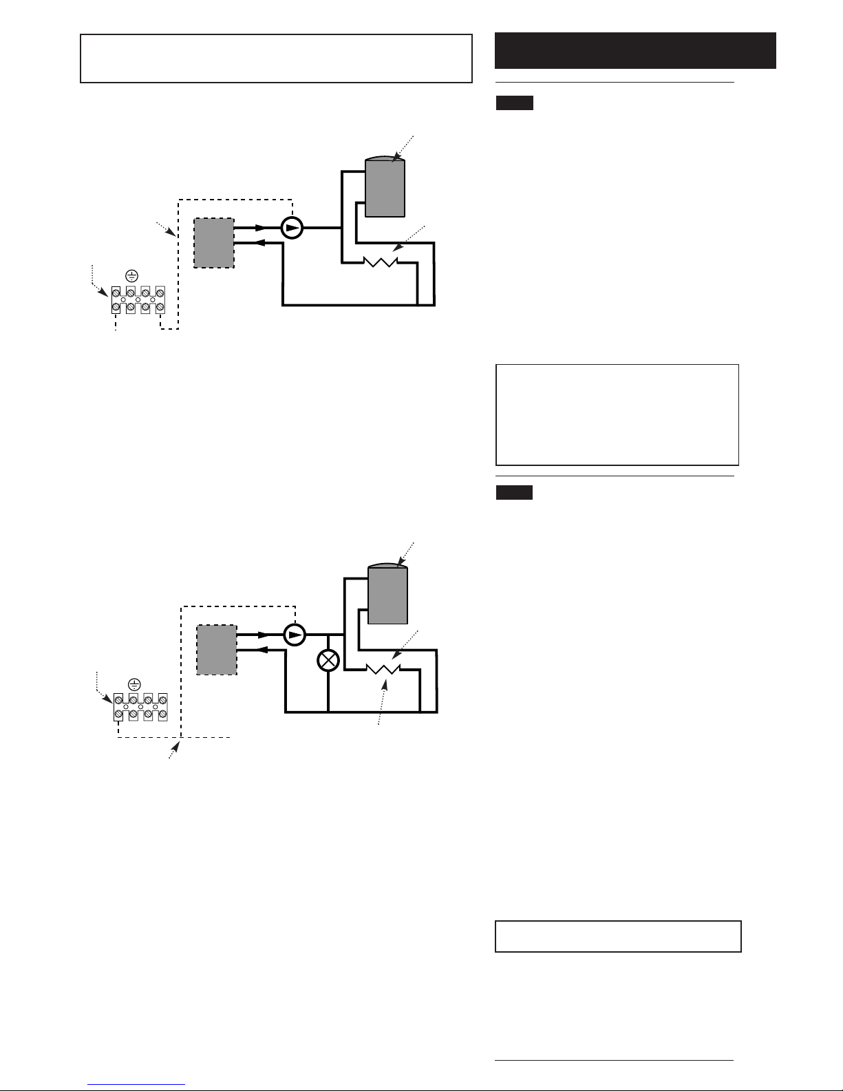
NOTE: Full TRV Systems (refer to section 6.4)
Where all the radiators are controlled by TRV’s
then pump protection will be required. This can be
done by either of the options opposite (see Fig A &
B). The option shown in Fig. A should only be
used on a full TRV system without a bypass.
Fig. B shows a system with a bypass that must
be capable of allowing a flow of at least 3 l/min.
6.2 Treatment of Water Circulating
Systems
• All recirculatory water systems will be subject to
corrosion unless an appropriate water treatment
is applied. This means that the efficiency of
the system will deteriorate as corrosion sludge
accumulates within the system, risking damage
to pump and valves, boiler noise and circulation
problems.
• When upgrading existing systems that exhibit
evidence of sludging, it is advisable to clean the
system prior to treatment in order to remove any
sludge and reduce the likelihood of these
deposits damaging new components.
• When fitting new systems flux will be evident
within the system, which can lead to damage of
system components.
• All systems must be thoroughly drained and
flushed out. The recommended flushing and
cleansing agents are Betz-Dearborn Sentinel
X300 or X400 and Fernox Superfloc Universal
Cleanser which should be used following the
flushing agent manufacturer’s instructions.
• System additives - corrosion inhibitors and
flushing agents/descalers should be suitable for
aluminium and comply to BS7593 requirements.
The only system additives recommended are
Betz-Dearborn Sentinel X100 and Fernox-Copal
which should be used followng the inhibitor
manufacturer’s instructions.
Failure to flush and add inhibitor to the
system will invalidate the appliance warranty.
• It is important to check the inhibitor
concentration after installation, system
modification and at every service in accordance
with the manufacturer’s instructions. (Test kits
are available from inhibitor stockists.)
• For information or advice regarding any of the
above contact the Baxi Helpline.
Boiler
No demand
for hot water
Central
heating
load
All TRV’s shut down
(boiler flow switch
causes pump to stop)
Live feed
to pump
Switch live from
programmer, etc.
S/L N
P/F
Fig. A Wiring to the pump feed connection of boiler
Fig. B Providing a 3 l/min bypass
Boiler
No demand
for hot water
Central
heating
load
All TRV’s shut down
(pump continues
around bypass)
Switch live from
programmer,
room stat, etc.
S/L
junction
S/L N
P/F
3 l/min
bypass
Boiler
Connections
Boiler
Connections
NOTE: This boiler does not require a bypass.
This boiler does not require a permanent live.
These diagrams only refer to pump protection for fully TRV’d systems.
6.0 System Details
10
6.3 Pipework
1. The sizes of flow and return pipes from the
boiler should be determined by normal methods,
according to the requirements of the system. The
connection to the boiler is 28mm (compression).
2. Due to space requirements within the boiler
outercase, pipework should comprise of solder
fittings.
3. A 20 °C (36°F) drop in temperature across the
system is recommended for condensing boilers.
Existing radiators may be oversized and so allow
this, but where radiator sizing is marginal it may be
advisable to retain a system temperature drop of
11°C (20°F).
4. In systems using non-metallic pipework it is
necessary to use copper pipe for the boiler Flow
and Return. The copper must extend at least 1
metre from the boiler and include any branches
(Fig. 7a).
6.4 System Controls
1. For optimum operating conditions, the heating
system into which the boiler is installed should
include a control system.
2. Such a system will comprise of a timer control
and separate room or cylinder thermostats as
appropriate. (An integral twin channel programmer
is available as an optional extra).
3. The boiler should be controlled so that it
operates on demand only.
4. Operation of the system under control of the
boiler thermostat & TRV’s only does not produce
the best results.
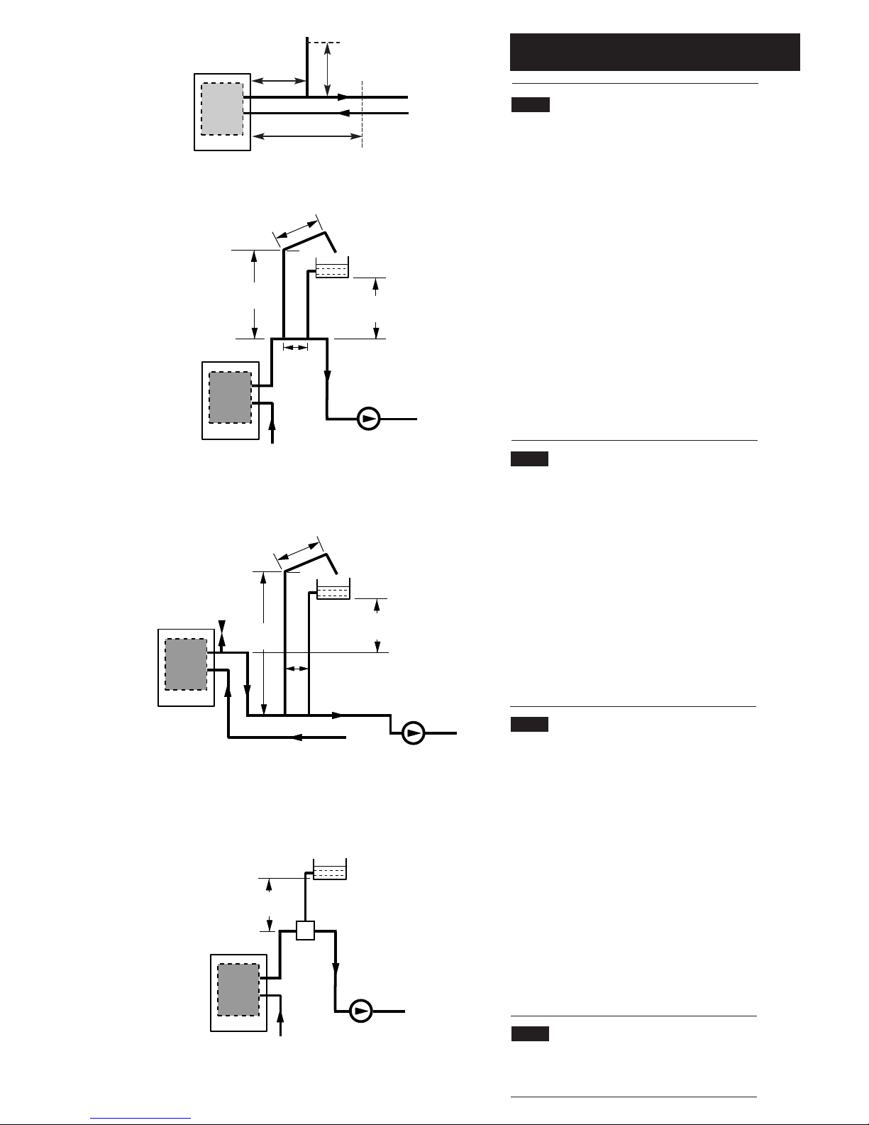
6.5 Low Head Installation
1. Using a close couple arrangement the minimum
head is as shown in the diagrams (Figs. 8 & 9)
subject to the following conditions:
a) The pump being adjusted to give an 20
o
C
drop across the boiler.
b) The pump must be fitted on the flow.
c) The pump must be fitted in accordance with
the pump manufacturer's instructions.
d) The open vent pipe must be taken up from a
tee in a horizontal section of the flow pipe.
An alternative Low Head Installation (Fig. 10)
2. For heads below 400mm then a combined vent
and feed pipe may be connected. This must be a
minimum of 22mm diameter. It is recommended
that an air separator is fitted when using a
combined feed and vent pipe.
6.6 Thermal Stores
1. When the 100 HE is fitted in conjunction with a
thermal store, jumper 2 must be removed from the
Control PCB, see Fig. 32a Section 8.8.
Typical Low Head Installation
If Conditions Require,
This System Possible
Alternative Low Head Installation
Boiler
500mm
45°
22mm
Open Vent
1000mm
Min
150mm
Max
15mm
Cold
Feed
400mm
Min Head
Return
Pump
Flow
Boiler
500mm
45°
22mm
Open Vent
400mm
Min Head
1000mm
Min
Automatic
Air Vent
15mm
Cold
Feed
150mm
Max
Return
Pump
Flow
Return
Pump
Flow
Boiler
200mm
Min
Air
Separator
22mm
Feed & Vent
Pipe
Fig. 8
Fig. 9
Fig. 10
Boiler
Flow
Return
Copper
0.5m
Copper
1m
Copper
0.5m
Fig. 7a
6.0 System Details
11
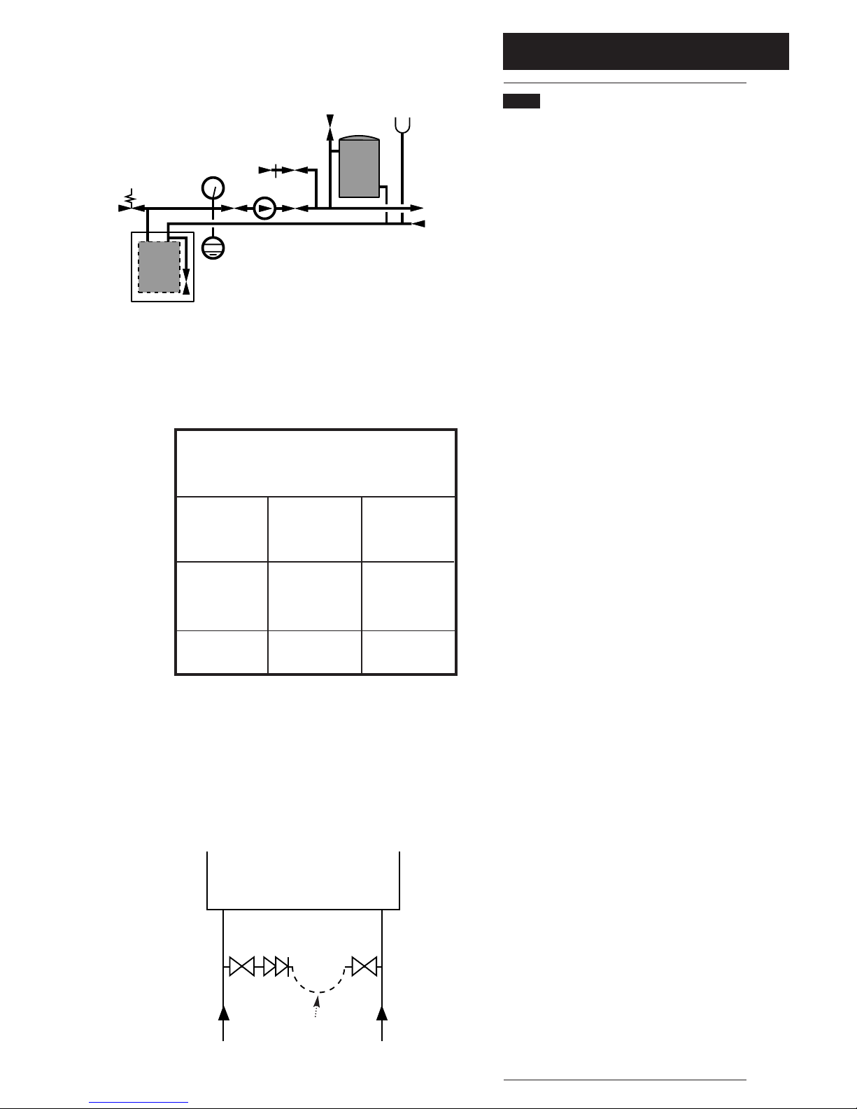
6.7 Sealed Systems
(Fig. 11)
1. SAFETY VALVE - A safety valve complying with
the requirements of BS 6750 Part 1 must be fitted
close to the boiler on the flow pipe by means of a
horizontal or vertically upward connection with no
intervening valve or restrictions and should be
positioned to facilitate testing. The valve should be
pre-set and non-adjustable to operate at a pressure
of 3 bar (45 Ibf/in
2
). It must be arranged to
discharge any water or steam through a pipe to a
safe outlet position.
2. PRESSURE GAUGE - A pressure gauge of
minimum range 0-4 bar (0-60 Ibf/in2) with a fill
pressure indicator must be fitted to the system,
preferably at the same point as the expansion
vessel in an easily visible position.
3. EXPANSION VESSEL - An expansion vessel
complying with the requirements of BS 4814 must
be fitted to the system by means of a connection
close to the inlet side of the circulating pump in
accordance with the manufacturers instructions, the
connecting pipe being unrestricted and not less
than 15mm (
1
/2in) nominal size. The volume of the
vessel should be suitable for the system water
content and the nitrogen or air charge pressure
should not be less than the system static head (See
Table. 1).
Further details of sealed system design can be
obtained from BS 5449 and the British Gas
publication entitled 'Specifications for Domestic Wet
Central Heating Systems'.
4. FILLING POINT - A filling point connection on
the central heating return pipework must be
provided to facilitate initial filling and pressurising
and also any subsequent water loss replacement /
refilling. The filling method adopted must be in
accordance with the Water Supply (Water Fittings)
regulations and the Water Bylaws (Scotland). Your
attention is drawn to: Paragraph 24 of Schedule 2
Section 8 of the publication Water Regulations
Guide which gives recommendations and guidance
on approved methods for filling sealed systems.
The sealed primary circuits may be filled or
replenished by means of a temporary connection
between the primary circuit and a supply pipe
provided the arrangement in accordance with
Diagram R24.2a of the Water Regulations Guide.
The temporary hose must be completely removed
at both ends after use.
5. MAKE UP SYSTEM - A method of replacing
water lost from the system should be provided
either by means of a make up vessel of not more
than 3 litres (5 pints) capacity, mounted above the
highest point of the system, or by re-pressurisation
of the system.
6. VENTING - A method of venting the system
during filling and commissioning must be provided
by fitting automatic air vents or by venting
manually.
7. HOT WATER STORAGE - The hot water
storage vessel must be of the indirect coil type. All
components used in the system must be suitable
for operation at 110°C (230°F) and at the pressure
allowed by the safety valve.
Safety
Valve
Pressure
Gauge
Pump
Filling
Point
Air
Vent
3 Litre
Top Up Bottle
(if required)
Radiator
Circuit
Expansion
Vessel
System Drains
at Low Point
Max Boiler Flow
Temp = 82° C
Boiler
Fig. 11
Table. 1
Vessel Charge
Pressure (Bar)
0.5
1.0
1.5
Initial System
Pressure (Bar)
0.5
1.0
1.5
2.0
1.0
1.5
2.0
1.5
2.0
Multiply Total
Water Content
Of System By
(Litres)
0.067
0.112
0.207
0.441
0.087
0.152
0.330
0.125
0.265
Method of determining minimum valve of
expansion vessel volume for sealed
systems using Baxi Boilers
System Volume = 75 litres
Vessel Charge Pressure = 1.0 bar
Initial System Pressure = 1.5 bar
75 x 0.152 = 11.4 litres
Expansion Vessel Volume
Example :-
Then :-
NOTE
Where a vessel of the calculated size is not obtainable
then the next available larger size should be used.
Stop
Valve
Double
Check
Valve
DHW
Mains
Inlet
CH
Return
Temporary
Hose
Stop
Valve
Fig. 11a
7.0 Site Requirements
12
7.1 Information
WARNING - Check the information on the data
plate is compatible with local supply conditions.
1. The installation must be carried out by a CORGI
Registered Installer or other registered competent
person and be in accordance with the relevant
requirements of the current G
AS SAFETY (Installation
and Use) R
EGULATIONS, the BUILDING REGULATIONS
(Scotland)(Consolidation), the LOCAL BUILDING
REGULATIONS, the current I.E.E. WIRING REGULATIONS
and the bye laws of the LOCAL WATER UNDERTAKING.
Where no specific instruction is given reference
should be made to the relevant BRITISH
STANDARD CODES OF PRACTICE. For Ireland
install in accordance with IS 813 “I
NSTALLATION OF
GAS APPLIANCES”. Reference should also be made
to B
RITISH GAS GUIDANCE NOTES FOR THE
INSTALLATION OF DOMESTIC GAS CONDENSING BOILERS.
7.2 B.S. Codes of Practice
Standard Scope
BS 6891 Gas Installation.
BS 5546 Installation of hot water supplies for
domestic purposes.
BS 5449 Part 1 Forced circulation hot water systems.
BS 6798 Installation of gas fired hot water boilers.
BS 5440 Part 1 Flues.
BS 5440 Part 2 Ventilation.
BS 7074 Expansion vessels and ancillary
equipment for sealed water systems.
BS 7593 Treatment of water in domestic hot water
central heating systems.
WARNING - The addition of anything that may
interfere with the normal operation of the
appliance without the express written permission
of Baxi UK Limited could invalidate the appliance
warranty and infringe the G
AS SAFETY
(Installation and Use) REGULATIONS.
7.3 Clearances (Figs. 12 &13)
1. A flat vertical area is required for the installation
of the boiler.
2. These dimensions include the necessary
clearances around the boiler for case removal,
spanner access and air movement. Additional
clearances may be required for the passage of
pipes around local obstructions such as joists
running parallel to the front face of the boiler.
3. For unventilated compartments see Section 7.5.
7.4 Location
1. The boiler may be fitted to any suitable wall with
the flue passing through an outside wall or roof and
discharging to atmosphere in a position permitting
satisfactory removal of combustion products and
providing an adequate air supply. The boiler should
be fitted within the building unless otherwise
protected by a suitable enclosure i.e. garage or
outhouse. (The boiler may be fitted inside a
cupboard - see Section 7.5).
2. If the boiler is sited in an unheated enclosure
then it is recommended to incorporate in the system
controls a suitable device for frost protection.
3. If the boiler is fitted in a room containing a bath or
shower reference must be made to the current
I.E.E. W
IRING REGULATIONS and BUILDING
REGULATIONS. If the boiler is to be fitted into a
building of timber frame construction then reference
must be made to the Institute of Gas Engineers
document UP 7.
50mm
600mm
390mm
200mm
5mm Min
5mm Min
5mm
500mm
For Servicing
Purposes
Fig. 12
Fig. 13
In Operation
3°
(1 in 20)
320mm
7.0 Site Requirements
13
7.5 Ventilation of Compartments
1. Where the boiler is installed in a cupboard or
compartment, no air vents are required for cooling
purposes providing that the minimum dimensions
below are maintained.
Sides 15mm
Top 200mm
Bottom 50mm
Front 30mm
2. If the boiler is installed in a smaller cupboard or
compartment it must be ventilated according to
BS 5440 Part 2 and the minimum clearances given
in section 4.0 “Technical Data” maintained.
3. Any compartment should be large enough to
house the boiler only.
NOTE: The ventilation label on the front of the
outer case MUST NOT BE REMOVED when
the appliance is installed in a compartment or
cupboard.
7.6 Gas Supply
1. The gas installation should be in accordance
with BS6891.
2. The connection to the appliance is a
1
/2in BSPT
internal threaded connection located at the rear of
the gas service cock (Fig. 15).
3. Ensure that the pipework from the meter to the
appliance is of adequate size.
(22mm pipework must be connected to the
appliance gas service cock. This should extend for
at least 3 meters back towards the gas meter).
Do not use pipes of a smaller diameter than the
boiler gas connection.
7.7 Electrical Supply
1. External wiring must be correctly earthed,
polarised and in accordance with current I.E.E.
W
IRING REGULATIONS.
2. The mains supply is 230V ~ 50Hz fused at 3A.
NOTE: The method of connection to the
electricity supply must facilitate complete
electrical isolation of the appliance. Connection
may be via a fused double-pole isolator with a
contact separation of at least 3mm in all poles
and servicing the boiler and system controls only.
7.8 Condensate Drain
NOTE: Ensure the discharge of condensate
complies with any national or local regulations
in force.
1. The condensate outlet terminates in a 1” BSP
nut and seal for the connection of 21.5mm (
3
/4in)
plastic overflow pipe which should generally
discharge internally into the household drainage
system. If this is not possible, discharge into an
outside drain is acceptable.
2. The pipe should run internally as much as
possible and with a 10° (1 in 6) fall to dispose of
condensate quickly to avoid freezing.
H
IG
H
L
O
W
Gas Service Cock
Fig. 15
7.0 Site Requirements
14
N
I
I
G
F
M
I
A
A
F
H
J,K
D
E
H
Likely flue positions requiring
a flue terminal guard
C
R
A
I
J,K
I
L
S
B
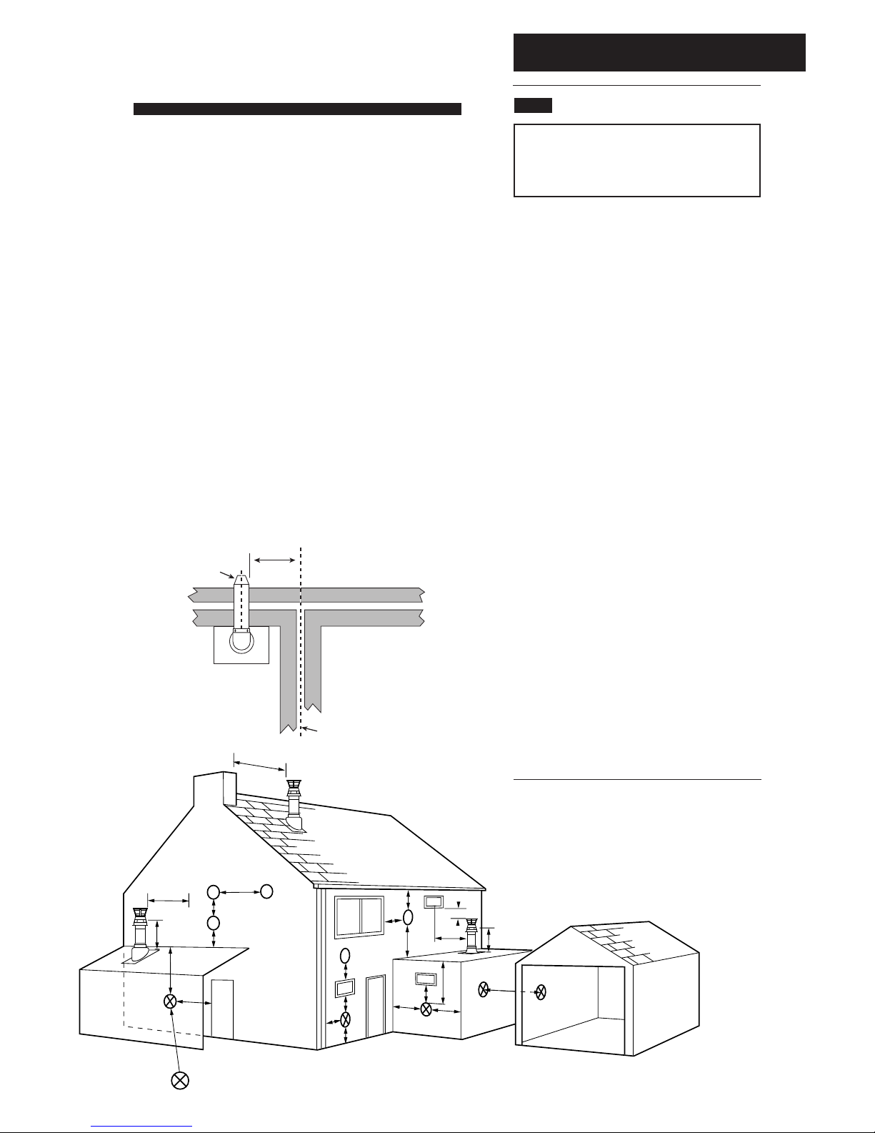
7.9 Flue
NOTE: Due to the nature of the boiler a plume
of water vapour will be discharged from the
flue. This should be taken into account when
siting the flue terminal.
1. The following guidelines indicate the general
requirements for siting balanced flue terminals.
Recommendations for flues are given in BS 5440
Pt.1.
2. If the terminal discharges onto a pathway or
passageway, check that combustion products will
not cause a nuisance and that the terminal will
not obstruct the passageway.
3. Take into consideration the effect the plume of
vapour may have on neighbours when siting the
flue.
4. Adjacent surfaces close to the flue terminal
may need protection from the effects of
condensation. Alternatively a flue deflector kit
(part no. 248167) is available.
5. For installation of the flue into an internal
corner at the 25mm dimension the flue deflector
kit (part no. 248167) must be fitted.
6. * Reduction to the boundary is possible down
to 25mm but the flue deflector kit (part no.
248167) must be fitted.
7. For fitting under low sofits and eaves it is
acceptable for the flue to project upto 500mm
from the face of the wall to the inside of the air
intake. This can be painted if required using a
suitable external paint.
8. If a terminal is less than 2 metres (78
3
/4in)
above a balcony, above ground or above a flat
roof to which people have access, then a suitable
terminal guard must be provided.
Fig. 17
Fig. 16
300 min
Terminal
Assembly
Top View Rear Flue
Property Boundary Line
NOTE: The distance from a fanned draught appliance
terminal installed parallel to a boundary may not be less
than 300mm in accordance with the diagram below
Table. 2
Terminal Position with Minimum Distance (Fig. 17) (mm)
AaDirectly below an opening, air brick, opening
windows, etc. 300
BaAbove an opening, air brick, opening window etc. 300
CaHorizontally to an opening, air brick, opening window etc. 300
D Below gutters, soil pipes or drain pipes. 25
E Below eaves. 25
F Below balconies or car port roof. 25
G From a vertical drain pipe or soil pipe. 25
H From an internal
(i)
or external
(ii)
corner.
(i)
25
(ii)
115
I Above ground, roof or balcony level. 300
J From a surface facing a terminal. 600
K From a terminal facing a terminal (Horizontal flue). 1200
From a terminal facing a terminal (Vertical flue). 600
L From an opening in carport (e.g. door, window)
into the dwelling. 1200
M Vertically from a terminal on the same wall. 1500
N Horizontally from a terminal on the same wall. 300
R From adjacent wall to flue (vertical only). 300
S From an adjacent opening window (vertical only). 1000
a
In addition, the terminal should be no nearer than 150 mm to an
opening in the building fabric formed for the purpose of accommodating
a built-in element such as a window frame. See BS 5440 Pt. 1.
*
7.0 Site Requirements
15
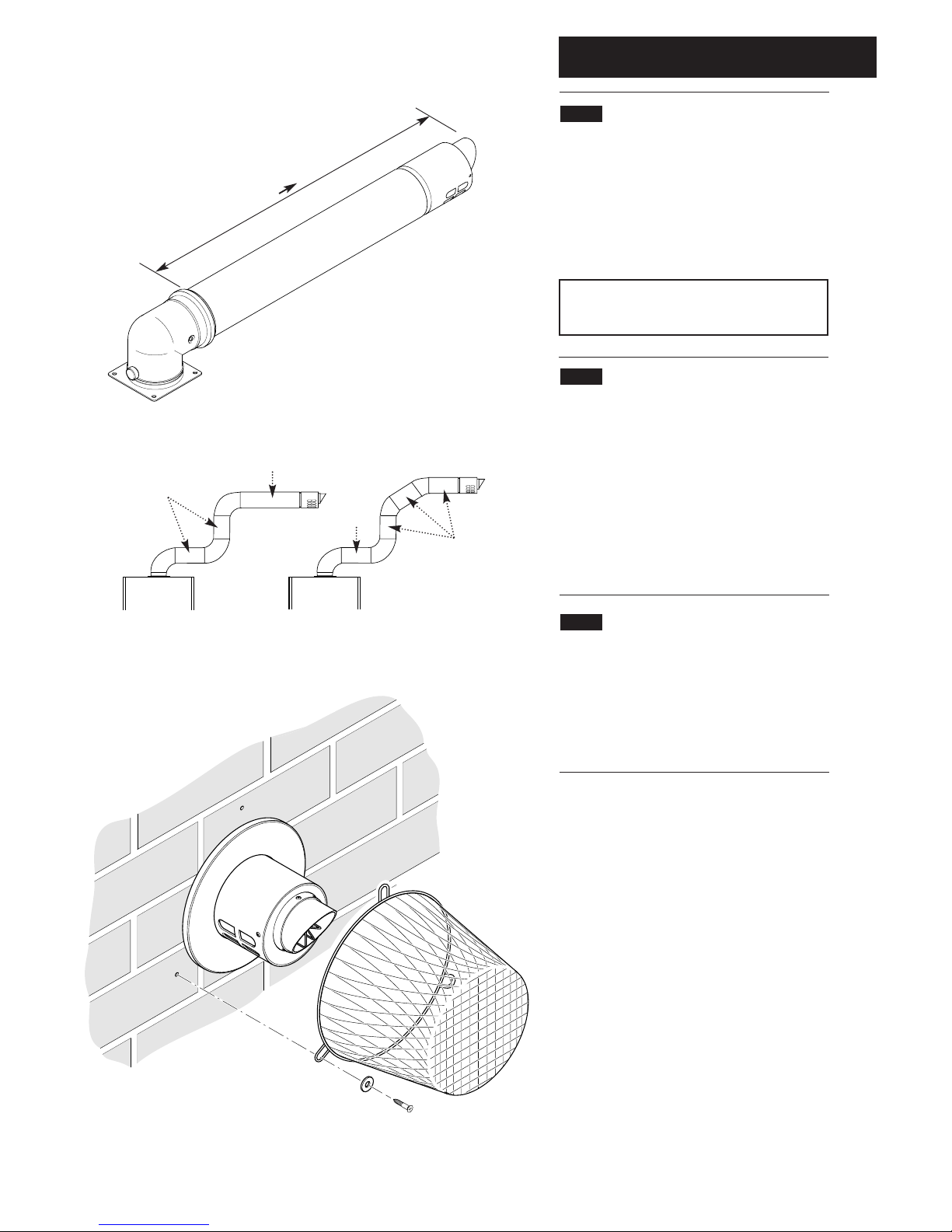
7.10 Flue Dimensions
See Section 1.2. The standard horizontal flue kit
allows for flue lengths between 270mm (10
5
/8”)
and 800mm (32”) from elbow to terminal
(Fig. 18).
The maximum permissible equivalent flue
length is: 4 metres (Fig. 18a).
NOTE: Each additional 45° of flue bend will
account for an equivalent flue length of 0.5m.
eg. 45° = 0.5m, 90° = 2 x 45° = 1m etc.
7.11 Terminal Guard (Fig. 19)
1. When codes of practice dictate the use of
terminal guards, they can be obtained from most
Plumbers’ and Builders’ Merchants.
2. When ordering a terminal guard, quote the
appliance model number.
3. The flue terminal guard should be positioned
centrally over the terminal and fixed as
illustrated.
7.12 Vertical Flue
1. Only a flue approved with the Baxi 100 HE
can be used.
2. For information on vertical flues consult the
Baxi High Efficiency Brochure or Notes for
Guidance supplied with the vertical flue pack.
Fig. 18
Fig. 18a
Pictorial examples of flue runs where EQUIVALENT flue length equals 4m
Fig. 19
270mm
800mm
0.5m
1m
0.5m
0.5m
 Loading...