

Page 1

HBZMXSIB/10/16SD-OP-1 Page 1
Operating Instructions
ZMX/BD/10
ZMX/BS/10
ZMX/CS/10
Multiplexers
Page 2

HBZMXSIB/10/16SD-PR-1 Page 1
Programming Instructions
ZMX/BD/10
ZMX/BS/10
ZMX/CS/10
Multiplexers
Page 3

HBZMXSIB/10/16SD-PR-1 Page 2
This page is intentionally blank
Page 4
HBZMXSIB/10/16SD-PR-1 Page 3
Passwords
This page contains the system passwords. It is recommend that, for system security,
you remove it from the manual and store it in a safe place.
The initial password, supplied with the unit for the menu system, is:
Password 1,
, ,
The password for resetting your multiplexer to the factory settings is:
Password 2,
You should change the password for the menu system (password 1) and record it
below for future reference.
Password
___________________________________________________________
Page 5

HBZMXSIB/10/16SD-PR-1 Page 4
This page is intentionally left blank
Page 6

HBZMXSIB/10/16SD-PR-1 Page 5
This Manual
This manual provides unpacking, safety and installation instructions for the
ZMX/BS/10, ZMX/BD/10 and ZMX/CS/10 Multiplexers. It also describes making
system settings, using the menu system.
Warning
Important safety instructions are contained in section 1. These must be read
before unpacking your multiplexer.
This manual is divided into five main sections:
Section 1, Important Safeguards, contains vital safety information, including the
Low Voltage Directive and EMC declaration, WARNINGS and CAUTIONS which
must be observed when installing the unit.
Section 2, Installation Instructions, contains instructions relating to unpacking,
associated equipment, mounting, and making connections to the unit. This section
includes rear panel connector layout illustrations and connector pinning information.
Section 3, Programming, describes the menu system, which allows access to the
system settings.
Section 4, Setting Up The System, describes how to set up the system using the
programming facilities.
Section 5, Specification, provides a brief technical specification.
Page 7

HBZMXSIB/10/16SD-PR-1 Page 6
This page is intentionally left blank
Page 8

HBZMXSIB/10/16SD-PR-1 Page 7
Contents
1 IMPORTANT SAFEGUARDS 9
1.1 Safety 11
1.2 Damage Requiring Service 12
1.3 Safety and Electromagnetic Compatibility (EMC) 12
1.4 Manufacturer’s Declaration of Conformance 13
1.5 Year 2000 Conformity 13
2 INSTALLATION INSTRUCTIONS 14
2.1 Unpacking 14
2.2 Associated Equipment 14
2.3 Location 14
2.4 Description 15
2.5 Connections 16
Camera Inputs 16
VCR 17
Monitor 18
Alarm Inputs And Outputs 18
Vext Input 20
Power 20
3 PROGRAMMING FACILITIES 21
3.1 Initial Actions After Switching On 21
Power-Up and Tests 21
3.2 Using The Menu System 22
Navigating The Menu System 22
The Available Menus 23
Battery Backed-Up Memory For The Menu Options 29
3.3 Setting Up The System 30
Camera Enable/Disable 30
Recording 30
Live Video Display 35
Playback 43
Alarms 47
Motion Detection 52
Special Functions 58
Macro Functions 60
Remote Control 64
Page 9

HBZMXSIB/10/16SD-PR-1 Page 8
4 SPECIFICATION 66
Feature Specification 66
Inputs and Outputs 66
Function Keys 66
Display Options 67
Record and Playback 67
Alarms Events 67
Alarm Responses 67
All Video Inputs and Outputs 67
Camera Switch Input (Vext) 68
Power 68
Physical Specifications 68
5 FUNCTION LIST 69
6 LIST OF SCHEDULED FUNCTIONS 70
APPENDIX A RS-232 REMOTE PROTOCOL
APPENDIX B FLICKER ADJUSTMENT
Page 10

HBZMXSIB/10/16SD-PR-1 Page 9
1 Important Safeguards
This product is exclusively for use in CCTV applications and has no other purpose.
Read and Retain the Instructions - All the safety and operating instructions should
be read before the unit is operated and should be retained for future reference.
Cleaning - Unplug the unit from the outlet before cleaning. Do not use liquid cleaners
or aerosol cleaners. Use a damp cloth for cleaning.
Attachments - Do not use attachments not recommended by the product
manufacturer as they may cause hazards.
Water and Moisture - Do not use this unit near water. For example, near a bathtub,
wash bowl, kitchen sink, or laundry tub, in a wet basement, near a swimming pool, in
an unprotected outdoor installation, or any area that is classified as a wet location.
Accessories - Do not place this unit on an unstable stand, tripod, bracket, or mount.
The unit may fall, causing serious injury to a person and serious damage to the unit.
Any mounting of the unit should follow the manufacturer’s instructions, and should
use a mounting accessory recommended by the manufacturer.
Ventilation - Openings in the enclosure, if any, are provided for ventilation to ensure
reliable operation of the unit and to protect it from overheating, these openings must
not be blocked or covered. This unit should not be placed in a built-in installation
unless proper ventilation is provided. Do not place directly on other hot equipment,
because this may increase its operating temperature.
Power Sources - This unit should be operated only from the class 2 isolated power
supply provided.
Plugs - This unit may be equipped with a 3-wire grounding-type plug, a plug having a
third (grounding) pin. This plug will only fit into a grounding-type power outlet. This is
a safety feature. If you are unable to insert the plug into the outlet, contact your
electrician to replace your obsolete outlet. Do not defeat the safety purpose of the
plug.
Power-cord Protection - Power-supply cords should be routed so that they are not
likely to be walked on or pinched by items placed upon or against them, paying
particular attention to cords at plugs, and the point where they exit from the
appliance.
Overloading - Do not overload outlets and extension cords as this can result in a risk
of fire or electric shock.
Object and Liquid Entry – This equipment must be protected from the ingress of
foreign materials. Never push objects of any kind into this unit through openings as
they may touch dangerous voltage points or short-out parts that could result in a fire
or electric shock. Never spill liquid of any kind on the unit.
Page 11

HBZMXSIB/10/16SD-PR-1 Page 10
Servicing – There are no user-serviceable parts. Do not remove the covers as this
may expose you to dangerous voltages or other hazards, including moving
mechanical parts. Refer all servicing to qualified service personnel.
Replacement Parts - When replacement parts are required be sure the service
technician has used the replacement parts specified by the manufacturer.
Unauthorised substitutions may result in fire, electric shock or other hazards.
Safety Check - Upon completion of any service or repairs to this unit, ask the service
technician to perform safety checks to determine that the unit is in proper operating
condition.
Coax Grounding - If an outside cable system is connected to the unit, be sure the
cable system is grounded.
Lightning - For added protection of this unit during a lightning storm, or when it is left
unattended and unused for long periods, unplug it from the wall outlet and disconnect
the cable system. This will prevent damage to the unit due to lightning and power-line
surges.
Page 12

HBZMXSIB/10/16SD-PR-1 Page 11
1.1 Safety
If you have any problems then contact Baxall Limited.
WARNING
Installation is only to be carried out by competent, qualified and experienced
personnel in accordance with the country of installation’s National Wiring
Regulations
WARNING
Your multiplexer contains no user-serviceable parts inside.
WARNING
This unit contains a lithium battery whose expected life is in excess of five years. If
your multiplexer looses its settings each time it is switched off then the battery
needs replacing. In this instance return your multiplexer to Baxall Limited and we
will replace the battery.
WARNING
There is a danger of explosion if the lithium battery is incorrectly replaced.
Replace only with the same or an equivalent type recommended by the
manufacturer. Dispose of unused batteries according to the manufacturers
instructions.
WARNING
Do NOT use the 12V power leads in the RS-485 cable UNLESS it is to be used on
a one-to-one connection between a unit with 12V power and a unit with no 12V
power. For example, from a multiplexer directly to a keyboard that does not have
its own power source.
In all other circumstances, such as multi-dropped multiplexers, do NOT use the
12V power leads in the RS-485 cable, use only the two wires for the actual 485
communications.
Refer to Baxall Limited before using your multiplexer in a medical and/or intrinsically
safe application.
Do not exceed the voltage and temperature limits given in the specification. Only
operate your multiplexer in a clean, dry, dust-free environment.
Note
The multiplexer’s main function is to multiplex video and its secondary function is
to provide alarms. For this reason, Baxall Limited recommend that you do not use
your multiplexer as the main alarm system on your site but install a dedicated
intruder/fire alarm where necessary.
Page 13

HBZMXSIB/10/16SD-PR-1 Page 12
1.2 Damage Requiring Service
Unplug the unit from the outlet and refer servicing to qualified service personnel
under the following conditions:
• When the power-supply cord or plug is damaged.
• If liquid has been spilled, or objects have fallen into the unit.
• If the unit has been exposed to rain or water.
• If the unit does not operate normally by following the operating instructions.
• If the unit has been dropped or the cabinet has been damaged.
• When the unit exhibits a distinct change in performance.
• If the unit has no power even when the power supply appears to operate
correctly. If this is the case then ask a service engineer to test the internal fuse.
1.3 Safety and Electromagnetic Compatibility (EMC)
Do not operate the unit outside the voltage and temperature limits given in the
specification.
WARNING
To reduce the risk of electrical shock, do not open covers. There are no user
serviceable parts inside. Refer servicing to qualified service personnel.
This product is intended for use in general purpose CCTV applications in a
residential, commercial or light industrial EMC environment.
Refer to your agent before installing or using the product in medical and/or
intrinsically safe applications or in an industrial EMC environment.
WARNING
This is a Class A product. In a domestic environment this product may cause radio
interference in which case the user may be required to take adequate measures.
The product must be installed in accordance with good installation practice to enable
the product to function as intended and to prevent problems. Refer to your agent for
installation guidance.
Contact your agent to obtain a specification defining the acceptable levels of product
degradation with regard to EMC immunity.
Page 14

HBZMXSIB/10/16SD-PR-1 Page 13
1.4 Manufacturer’s Declaration of Conformance
The manufacturer declares that the product supplied with this document is compliant
with the essential protection requirements of the EMC directive 89/336 and the Low
Voltage Directive LVD 73/23 EEC. Conforming to the requirements of standards EN
55022 for emissions, IEC801 parts 2, 3 and 4 for immunity and BS415 superseded
by EN60950 for Electrical Equipment safety.
1.5 Year 2000 Conformity
This product, which contains date and time-aware components, has been tested in
accordance with British Standards Institution, DISC PD2000-1, A Definition of Year
2000 Conformity Requirements, and complies with the four rules set out in the
document.
Rule 1. No value for the current date will cause any interruption in operation.
Rule 2. Date-based functionality must behave consistently for dates prior to, during
and after year 2000.
Rule 3. In all interfaces and data storage, the century in any date must be specified
either explicitly or by unambiguous algorithms or inferencing rules.
Rule 4. Year 2000 must be recognised as a leap year.
This product uses a two digit year format, with the following inferencing rule:
Displayed year = 00 to 89 Inferred year = 2000 to 2089
Displayed year = 90 to 99 Inferred year = 1990 to 1999
The clock chip is a Dallas 1202.
Page 15

HBZMXSIB/10/16SD-PR-1 Page 14
2 Installation Instructions
This section describes the unpacking and installation of your multiplexer.
2.1 Unpacking
You should keep the original packing for use when the unit has to be stored or
transported. The packaging should contain the following items:
• The multiplexer unit
• A mains power supply and lead
• An Operating Instructions manual
• This Programming Instructions manual
Carefully check the unit for signs of damage. If damage has occurred, please contact
the supplier and the carrier immediately and do not attempt to use the equipment.
2.2 Associated Equipment
A typical system, using this multiplexer, could contain the following components:
• A monitor
• A VCR (Standard or S-VHS)
• Cameras with 1V pk-pk composite video outputs
• 75 ohm BNC connectors and video coaxial cable for connecting the video
signals.
• S-VHS connectors and leads if you are using an S-VHS VCR
• A mains power outlet for your multiplexer which allows for secure isolation
(your Multiplexer has no ON/OFF switch for security reasons) in accordance
with your national wiring regulations.
2.3 Location
Ensure that the site’s AC power supply is stable and within the rated voltage of the
external 12V DC power supply. If the site’s AC power is likely to have spikes or
power dips, use power line conditioning or a UPS.
Ventilation: Ensure that the location planned for the installation of the unit is well
ventilated. Take note of the locations of the cooling vents in the unit’s enclosure, and
ensure that they are not obstructed.
Temperature: Observe the unit’s ambient temperature specifications when choosing
an installation space. Extremes of heat or cold beyond the specified operating
temperature limits may cause the unit to fail.
Do not install the unit on top of other hot equipment.
You can place your monitor on top of the multiplexer if it weighs less than 16 Kgs.
Page 16
HBZMXSIB/10/16SD-PR-1 Page 15
2.4 Description
The products described in this manual are:
• ZMX/BS/10, 10-way, Monochrome Simplex Multiplexer
• ZMX/BD/10, 10-way, Monochrome Duplex Multiplexer
• ZMX/CS/10, 10-way, Colour Simplex Mult iplexer
You can check which particular model you have by looking at the label on the bottom
right of the unit’s front panel.
The models include many advanced features such as activity detection, alarm
handling, digital zoom, an alarm history log, programmable macro function keys, a
scheduler to automatically start macros at pre-set times, a simple Summer/Winter
time change function, access to Rugby Clock time control, remote programming and
remote control, and they can be set-up quickly using easy-to-use on-screen menus.
With all of the models, the front panel contains all the operator control keys and
indicators, while the video inputs, video outputs, alarm inputs and outputs, and the
remote control connectors are housed on the rear panel.
All the models have 12 V DC power and are supplied with external AC power
supplies. The colour models can accept either colour or monochrome video inputs
without any additional set-up.
In general, the programming instructions provided in this document apply to all of the
above models unless stated otherwise.
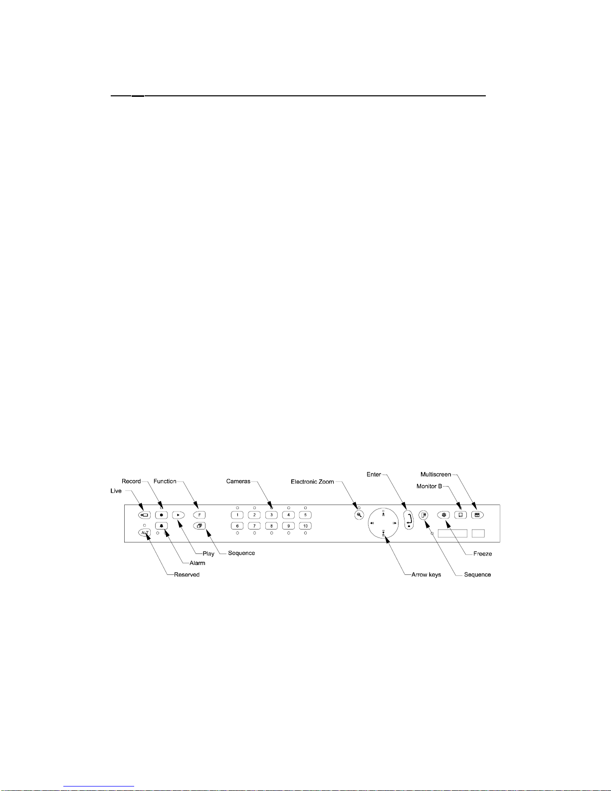
The front panel for the 10 way colour simplex model is shown in Figure 1. The other
models have the same keys and indicators except, in the case of the 16 way models,
which have 16 instead of 10 camera keys.
Figure 1 The multiplexer Front Panel
From an installation point of view the eight powerful MACRO style FUNCTIONS are
useful to be able to control any or all the system settings with only 2 keystrokes.
Page 17
HBZMXSIB/10/16SD-PR-1 Page 16
2.5 Connections
The following instructions relate to the multiplexer only. Refer to the relevant
instructions for the associated equipment.
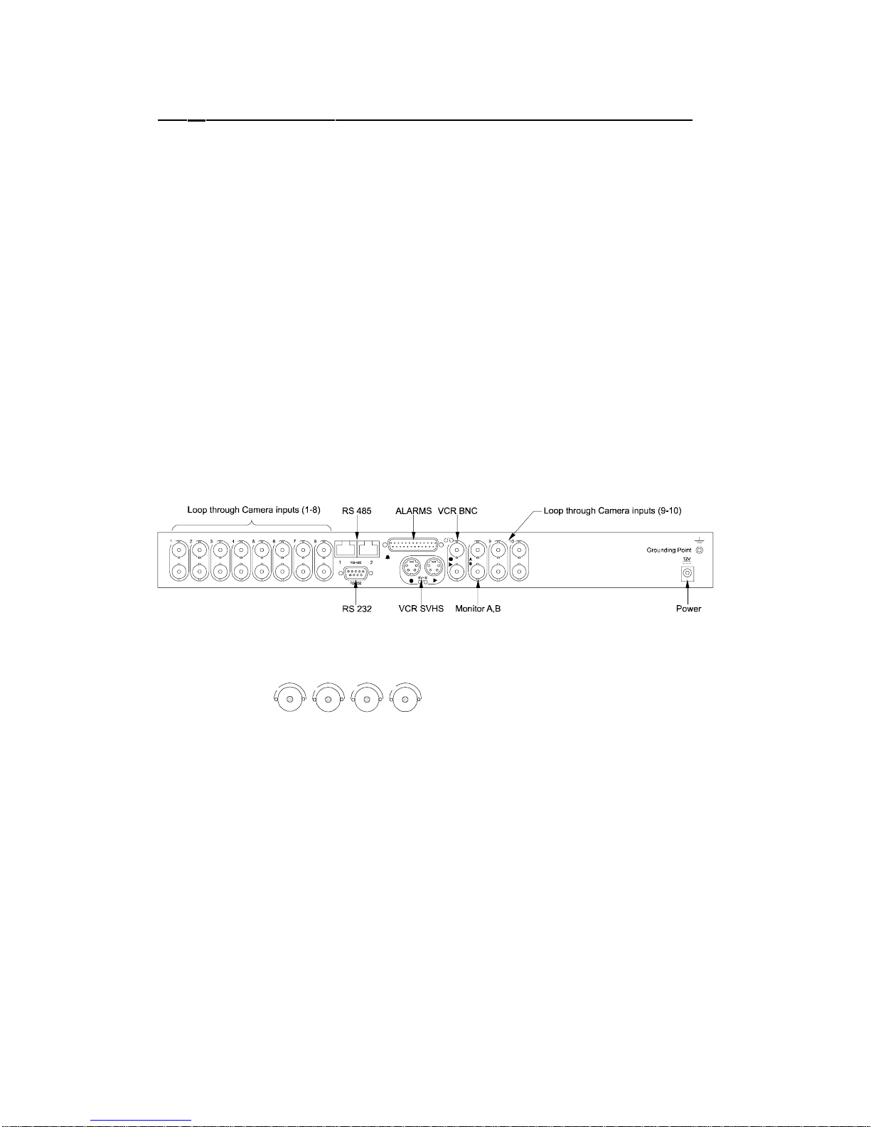
All the connectors are on the back-panel of your multiplexer as shown in Figure 2.
Your multiplexer has:
10 or 16 loop-through camera inputs (depending on the model) with automatic
termination
twin monitor outputs, Monitor-A and Monitor-B
VCR input and output via BNC or S-VHS connectors
10 or 16 alarm-inputs (on a 25-way D-type connector) each of which can be
normally-open (N/O) or normally-closed (N/C).
RS-232 and RS-485 connectors (Rugby clock connection).
The 25-way D-type connector also has the contacts for the two alarm-output relays
and a Vext input. The Vext input accepts a synchronising pulse-train from your VCR
(see your VCR’s instructions). This allows the multiplexer to follow automatically the
time-lapse speeds of the VCR.
Figure 2 Multiplexer Back-Panel Connections
Camera Inputs
4321
Use 75 ohm BNC connectors and video coaxial cable to connect to the camera input
BNC sockets on the back of your multiplexer.
For each camera input there are a pair of BNC sockets, one for the camera input, the
other for a looped through output. If you connect to both BNC sockets your
multiplexer automatically removes the 75 ohm termination. If you use the loop
through facility make sure that your application (e.g. a monitor or VCR) provides 75
ohm termination at the end of the line.
Connect up to your 10 or 16 camera inputs. You can use either the upper or the
lower sockets.
Connect your loop through outputs to the through BNC socket in each pair.
If you have less than 10 or 16 cameras, you can disable individual camera inputs in
the menu system, see page 27.
Page 18
HBZMXSIB/10/16SD-PR-1 Page 17
VCR
This consists of video connection and the Vext input (via a 25-way D-type connector,
the synchronising pulse train from the VCR, connection.
For an S-VHS VCR, use 4-pin mini-din S-VHS connectors and leads. For a standard
VCR use 75 ohm coaxial cable and BNC connectors.
If you are using S-VHS, then to get the full benefit, you must also select it in the VCR
Setup menu.
Although the Vext connection is optional, by using it, you can automatically
synchronise your VCR with the multiplexer. This simplifies the operation of your
multiplexer. For connection to the Vext input, the Switch Input option must be used in
the VCR Setup in the menu system.
Note
Some time-lapse VCRs do not transmit a Vext signal in 3 hour mode. In this case,
if you are using the Vext input then select 3 hour mode in both the Alarm Record
Speed and Normal Record Speed menu via the Record option in the main menu.
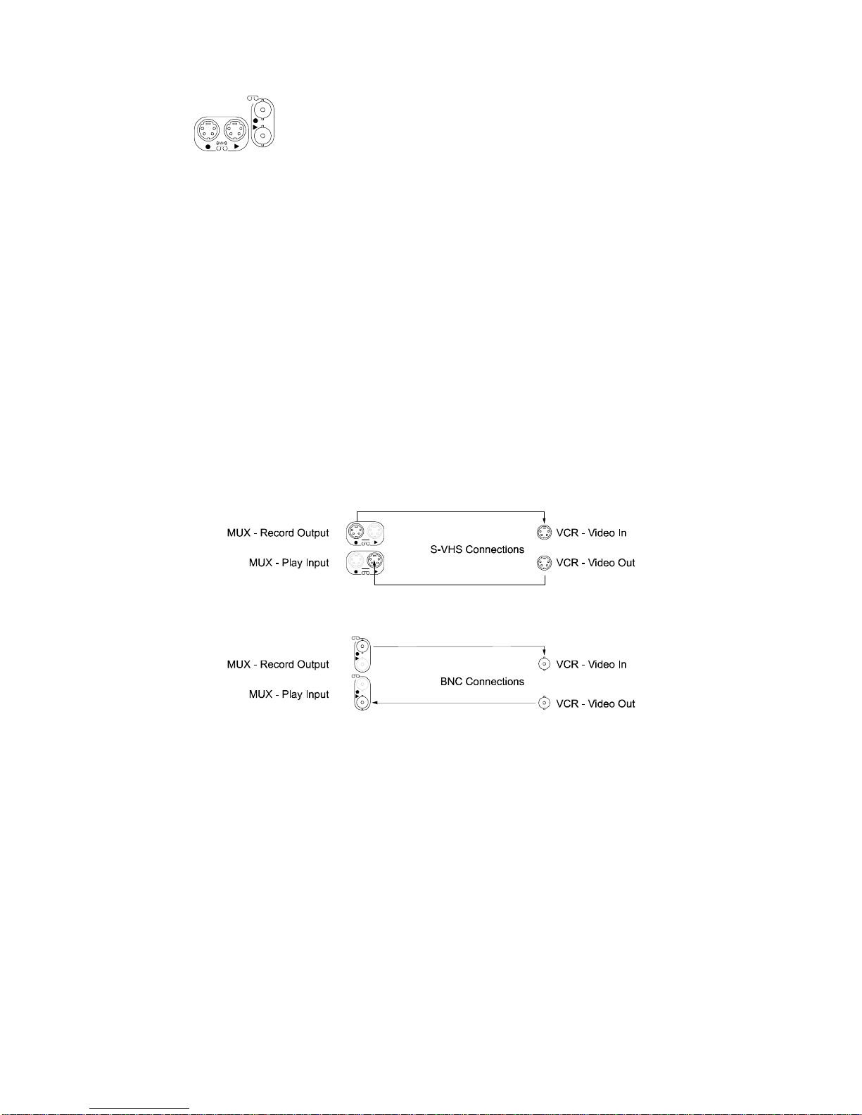
Figure 3 S-VHS VCR connections
Figure 4 Standard (BNC) VCR connections
Refer to your VCR instructions and connect:
VCR record output to the video in connector (or equivalent) on your VCR.
VCR play input to the video out connector (or equivalent) on your VCR.
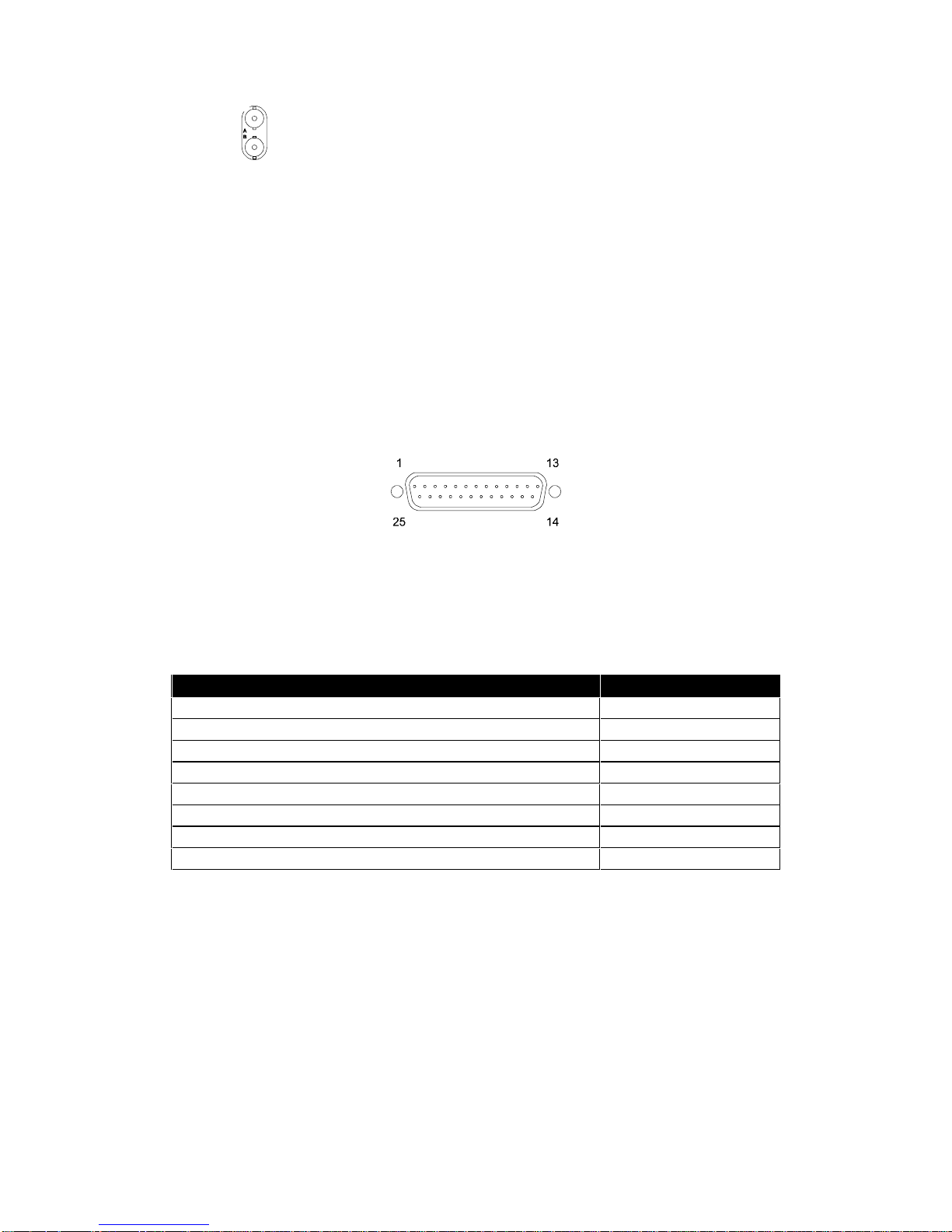
The illustration indicates that the two leftmost connectors are VCR record outputs
and the two right hand connectors are VCR play inputs (see Figures 3 and 4).
Page 19
HBZMXSIB/10/16SD-PR-1 Page 18
Monitor
Connect the MONITOR output using 75 ohm BNC connectors and video coaxial
cable to your monitor(s) (see your monitor instructions).
When viewed from the rear of the unit, the left-hand connector is for Monitor-A and
the right-hand is for Monitor-B.
Alarm Inputs And Outputs
25-way D-type Connector
Using the 25-way D-type connector, wire it according to the following instructions. Do
not attempt to wire directly to the socket on the back-panel.
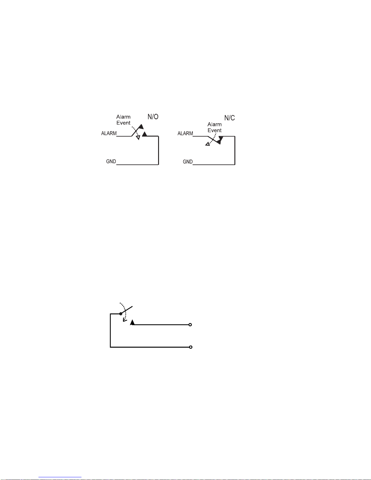
Figure 5 The 25-way D-type Connector Numbering
Figure 5 shows the connector, looking towards the rear panel. The numbers are
labelled on the connector itself although they may be difficult to read.
Connections Pin numbers
Alarm inputs 1 to 10; or 1 to 16 pins 1 to 10 (or 16)
Alarm-output 1 - connection (selectable N/O or N/C) pin 17
Ground connections - (alarms and Vext inputs) pins 18 to 20
Alarm-output 1 - common ground connection pin 21
Alarm-output 2 - connection (selectable N/O or N/C) pin 22
External alarm clear (pull to ground to clear) pin 23
Vext, VCR synchronisation pulse-train pin 24
Alarm-output 2 - common ground connection pin 25
Table 1 25-way D-type Connections
Page 20
HBZMXSIB/10/16SD-PR-1 Page 19
Alarm Inputs
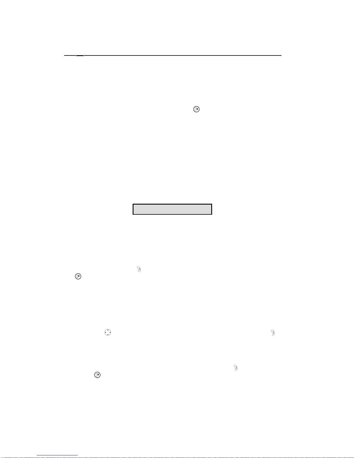
Each alarm input line can be triggered by a relay contact from devices such as
pressure-pads, passive infrareds, smoke detectors etc. (refer to the relevant
instructions).
The alarms are disabled while the menu system is active.
Figure 6 Normally-Open and Normally-Closed Connections
Alarm Outputs
Note
Do not exceed 30V AC/DC, 500 mA on an alarm-output relay.
The contacts must not be used at mains voltages.
The alarm output relays can be programmed in the menu system to respond to
macro-functions, alarms and video-loss. The relays are active (see Figure 7) for the
duration of the driving event.
Connect your application to the alarm-output relays (resistive loads only).
Figure 7 Alarm-Output Relays, Internal Circuitry
External Alarm Clear
You can use the External Alarm Clear to clear alarms by connecting it to ground on
pins 18, 19 and 20. Clearing an alarm only clears the LED and the keyboard buzzer.
The alarm output relay is always active for the duration of the alarm input. If the
alarms are selected as latched or timed-out in the Alarms menu then the alarmoutput can remain active after the alarm input has reset.
Alarm Output
N/O Connection
Alarm Output
Common Connectio
n
Alarm
Page 21

HBZMXSIB/10/16SD-PR-1 Page 20
Vext Input
The Vext input (camera switch input) is for connection from the VCR to your
multiplexer. The VCR uses it to tell the multiplexer each time it has recorded an
image. The multiplexer then transmits the next image on its VCR record output
(video-in on the VCR). By this mechanism the VCR can control the multiplexers
recording speed.
Connect the Vext input (pin 24) and one of the ground pins to your VCR.
This facility is often referred to as a camera switch output, or similar, (see your VCR
instructions.) It is especially useful on VCRs with dual recording speeds (alarm and
normal) because the multiplexer will automatically follow.
Note
Some VCRs do not transmit a Vext in 3 hour mode. To ensure that this does not
affect you, set the recording speeds for alarms and normal operation to be the
same in the RECORD menu.
The Vext input accepts:
• TTL, field-synchronised, negative going pulse, duration 2-5 ms
• HIGH level, +4.5V to +5.5V
• LOW level, 0V
The multiplexer can be set to trigger off the negative or positive going edge (Vext
Pulse Edge in the Record menu). There is also an option to allow compatibility with
some older types of VCR (VCR type A and type B compatibility, also in the Record
menu).
Check this against your VCR specification before using it.
Power
The multiplexer is supplied with a 12V DC class 2 output, auto-ranging: 110/230V AC
± 10%, 50Hz, input, external power supply. Its maximum power consumption is 20W.
Do not use any other power supply.
Do not connect the power until you have read the section Power-Up and Tests.
Following the wiring instructions on the label attached to the mains lead, attach a
suitable three pin plug.
Note
The manufacturer accepts no responsibility for any damage caused by the use of
any other power supply.
Page 22

HBZMXSIB/10/16SD-PR-1 Page 21
3 Programming Facilities
This section describes the facilities provided for programming your multiplexer using
the menu system.
Note
The ALARM key
is disabled while the menu system is active.
3.1 Initial Actions After Switching On
The first time that your multiplexer is switched on, the default password for the menu
system is set to password 1 (given on the removable page at the front of these
instructions.) This is also true if you have reset to Factory Settings.
Once your installation is complete, turn on the power. Your multiplexer will start by
displaying the software version and then a multi-screen display on Monitor-A. If you
have previously changed any settings in the Menu system, your settings are still
stored while the power is off and are now current.
Power-Up and Tests
Note
Read all the operating instructions before operating the unit.
• Power up all the cameras and the monitor, and only then power up the unit by
plugging in the 12V DC class 2 isolated supply.
• With the unit in record mode, select each camera, full-screen, and check the
picture quality. This is live video. If the picture quality is poor, check the loopthrough terminations, the levels of incoming signals and ground loops.
• Record/Play quality: Record for 3 minutes at normal VCR speed (3 hour mode)
and then play back the recordings, selecting each camera in turn. Check the
playback picture quality. Ensure that the VCR’s tracking adjustment is correct.
• For advice on setting-up cameras refer to your camera installation instructions.
• Test the VCR Vext switch pulse connection to the unit by setting the unit to
Record mode, starting the VCR recording and then changing the VCR record
speed on the VCR front panel. Play back the recording and observe that the unit
displays Pext in the top right corner of your monitor.
• Alarms: Activate an alarm and observe that the programmed alarm actions take
place, the buzzer sounds and the alarm LED flashes.
Page 23
HBZMXSIB/10/16SD-PR-1 Page 22
3.2 Using The Menu System
Your multiplexer provides user-friendly, on-screen menus for setting up the system.
As an alternative to on-screen programming in the menus, the options can be
downloaded via the RS-232 port from a central controller or PC. The protocols for
this are given in Appendix A.
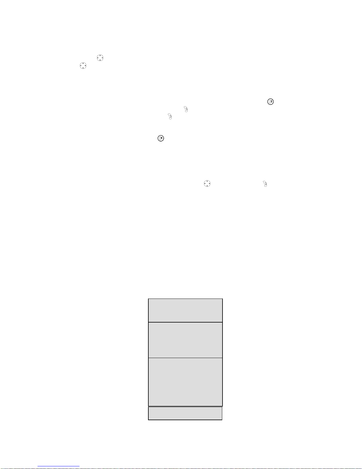
To enter the menu system, press the MENU key
and enter the 3-key password.
The password is set to password 1 in the front of this manual when the unit is
shipped. You should change the password (using the menu system) and remove the
password page from the front of this manual to prevent unauthorised use of the menu
system.
Caution: Simplex Units
The menu operation will
stop
RECORD mode on
simplex
units if the
password is correctly entered. Ensure that it is appropriate to
stop all
recording
before entering the password.
The MAIN menu bar will appear once the correct password has been entered.
Navigating The Menu System
You have three menu levels, designed in such a way as to make it very easy to
navigate around the menu choices. The best way to understand the menu system is
to use it, with this manual handy for reference.
In general, the ENTER key
is used to go to the next level of menu, and the MENU
key
is used to ‘escape’ to the previous level of the menus without making any
changes.
You have access to the following menu levels:
Main Menu Level
This is a list of all sub-menus, each of which you can access. The sub-menus are
arranged into logical menu sections. To access a sub-menu from the Main menu, use
the arrow keys
to select the desired section and then press the ENTER key .
Pull-down Menus
Pull-down menus are the first sub-menu level. If additional choices are available in
that sub-menu, typically these are made in Pop-up menus. Pull-down menus can be
exited either by selecting Exit and then pressing the ENTER key
, or by pressing the
MENU key
.
MainQuick-Setu
p
Page 24
HBZMXSIB/10/16SD-PR-1 Page 23
Pop-up Menus
Pop-up menus are the last level in the menu system. In general, use the left/right
arrow keys
to select sections in the Pop-up menu and then use the up/down arrow
keys
to make changes to the values. There are, however, some Pop-up menus
where the arrow keys have additional functionality.
In Pop-up menus, there are no EXIT selections.
To exit a Pop-up menu without making any changes, press the MENU key
or else
select [CANCEL] and press the ENTER key
. To exit and save the changes made,
select [OK] and press the ENTER key
.
CAUTION: Pressing MENU to exit from a sub-menu will
not
save the changes made
in that sub-menu. The MENU key
is the same as CANCEL.
The Available Menus
The Menu Bar enables you to select Main or Quick-Setup. To do this highlight the
one that you want using the left or right arrow keys
and press ENTER .
If you select Main, the main Menu is displayed. If you select Quick-Setup, the QuickSetup menu is displayed.
The Main Menu
The Main Menu gives you access to all the programmable options, in logical subsections.
The programmable options provided are described in detail in section 3.3. You
should read the corresponding section in the manual
before
starting to program the
options in the menus.
The main menu has the following options:
Time/Date
Sequencing
Record
Camera Titles
Alarms
Macro
Motion Detection
Camera AGC
Exit
Communications
Camera Enable
Videoloss Action
Playback Format
VCR Setup
Factory Settings
Change Password
Page 25
HBZMXSIB/10/16SD-PR-1 Page 24
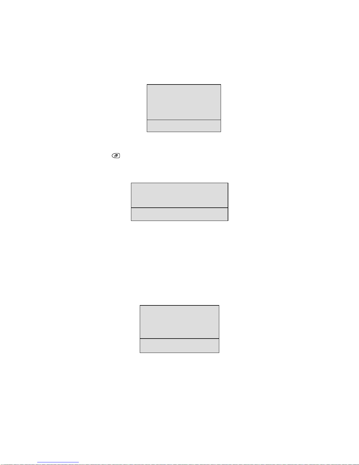
Time/Date
This option lets you specify whether the data and time are to be displayed on Monitor
A and Monitor B, and what format is to be used. You can also set the time and date.
You get the following pull-down menu:
Sequencing
This option is used to specify the full-screen sequence list (as displayed when the
SEQUENCE key
is pressed), the multi-screen dwell time (for the sequencing
cameo in multi-screen mode) and the full-screen dwell time. You get the following
pull-down menu:
Note
You cannot edit the sequence list for cameo sequencing.
Record
This option is used to specify the order in which images are to be captured from the
different input cameras. You can specify the normal record speed for the VCR, the
alarm record speed, and whether or not Record Lock is to be used (for simplex
models). You get the following pull-down menu:
Time/Date display
Set Time Format
Set Date Format
Set Time
Set Date
Exit
Fullscreen Sequence List
Multiscreen Dwell
Fullscreen Dwell
Exit
Record List
Normal Record Speed
Alarm Record Speed
Record Mode Lock
Exit
Page 26
HBZMXSIB/10/16SD-PR-1 Page 25
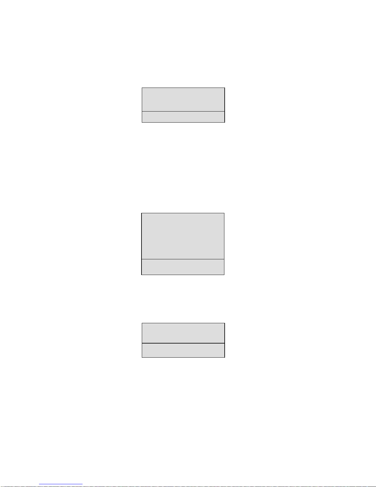
Camera Titles
This option is used to specify whether camera titles are to be displayed on monitor A
and B, and to edit those titles for each camera. You get the following pull-down
menu:
Alarms
This option is used to specify whether the alarm input for each camera is normally
open or normally closed and whether the alarms are latched, transparent or timed
out. You can specify how the images from the alarmed cameras are to be recorded
(interleaved, exclusive or no change) and whether some or all of the alarms are to be
enabled or disabled. You can view the alarm history for the last 100 alarms and
specify whether the alarm output relays are normally open or normally closed.
You get the following pull-down menu:
Macro
This option is used to specify macros and to set up the details for timed macros. You
get the following pull-down menu:
Title Display
Edit Titles
Exit
Input Configuration
Alarm Latch
Record Mode
Enable / Disable
Alarm History
Relay Configuration
Exit
Macro Record
Timed Macro Start
Exit
Page 27
HBZMXSIB/10/16SD-PR-1 Page 26
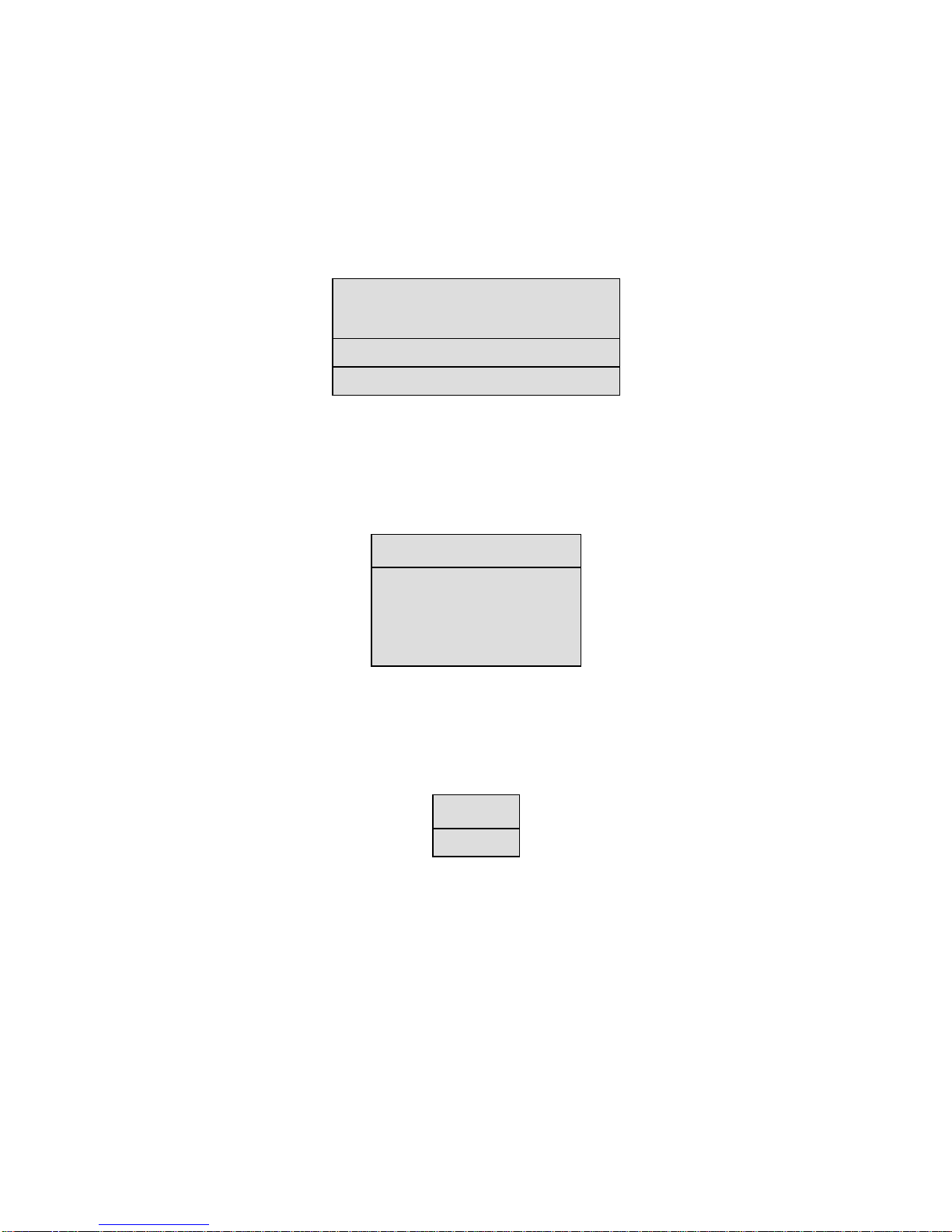
Motion Detection
This option is used to specify whether motion detection is enabled for individual or all
the cameras. For each camera, you can specify which zones in the camera’s view
are to be active for motion detection. You can specify whether a motion detection
indicator is to be displayed on the monitor and for each camera, the motion detection
sensitivity, record rate and output relay to be used. You get the following pull-down
menu:
Camera AGC
This option is used to specify the signal gain to be used for each camera. You get the
following pull-down menu:
Communications
This option is used to specify the communications baud rate to be used. You get the
following pull-down menu:
Enable / Disable Detection
Setup Active Zones
Indicate Detection
Setup Parameters
Exit
Signal Gain Setup
Camera : 01
Gain : 05
[CANCEL] [OK]
RS232
Exit
Page 28
HBZMXSIB/10/16SD-PR-1 Page 27
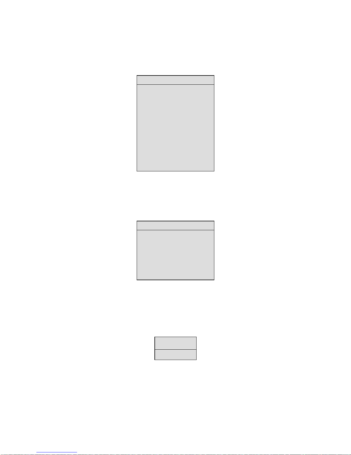
Camera Enable
This option is used to specify which cameras are enabled or disabled. You get the
following pull-down menu:
Videoloss Action
This option is used to specify what is to happen in the event of loss of a video input.
You get the following pull-down menu:
Playback Format
This option is used to specify the playback format for a multiplexed tape. You get the
following pull-down menu:
Camera
Enabl
e
Camera 01: ENABLE
Camera 02: ENABLE
Camera 03: ENABLE
Camera 04: ENABLE
Camera 05: ENABLE
Camera 06: ENABLE
Camera 07: ENABLE
Camera 08: ENABLE
Camera 09: ENABLE
Camera 10: ENABLE
[CANCEL] [OK]
Videoloss Actio
n
Camera : 01
Relay 1: DISABLE
Relay 2: DISABLE
Buzzer : DISABLE
[CANCEL] [OK]
Default
A
lternate
Page 29

HBZMXSIB/10/16SD-PR-1 Page 28
VCR Setup
This option is used to specify the type of VCR that is connected to the multiplexer.
You specify whether it is type A or B, SVHS or composite, whether it has switch input
and whether it has a negative or a positive leading edge. You get the following pulldown menu:
Factory Settings
This option is used to specify that the multiplexer is to be reset with the factory
settings. You get the following password box:
You must enter the correct password to reset to the factory settings.
Change Password
This option is used to change the password for the menu system. You get the
following password box:
When you have entered a new password, a confirmation box is displayed where you
must specify the same password again. You should note the new password on the
Password page of this document, which should be removed and stored in a safe
place.
Exit
This option is used to exit from the menu system.
V
CR Type A/B
SVHS/Composite
Switch Input ON/OFF
Switch Edge
Exit
Please enter the Factory Password
|---|
[CANCEL] [OK]
Enter a new Password
|---|
[CANCEL] [OK]
Page 30

HBZMXSIB/10/16SD-PR-1 Page 29
Quick-Setup Menu
The Quick-Setup menu gives you a quick way to change the time and date, and to
edit the titles for each camera. You can set the normal record speed and the
playback format and specify whether the connected VCR is composite or SVHS
(colour units only). This allows for a quick minimal installation set up. You get the
following pull-down menu:
Battery Backed-Up Memory For The Menu Options
Menu option selections are automatically saved to battery backed-up memory as
they are made.
In general, the battery has a 5 year shelf life and can retain memory in the unit even
if the unit is powered down for several months. If a unit is to be powered down for an
extended time (3 months or longer) then the battery should be removed during power
down, and replaced when the unit is ready to be put back into service. Alternatively,
install a new battery when a unit has been powered down for an extended time.
Warning
Battery installation must be done only by qualified personnel.
Note
All the data will be lost if the battery is removed, and the system will revert to the
factory defaults.
Your Multiplexer stores your settings as you make them in non-volatile memory. This
means that you can exit the MENU system at any time and you will not lose your
settings, provided you have already selected OK where appropriate, and pressed the
ENTER key
.
Change the time
Change the date
Edit Camera Titles
Normal Record Speed
Playback Format
SVHS/Composite
Exit
Page 31
HBZMXSIB/10/16SD-PR-1 Page 30
3.3 Setting Up The System
This section describes the use of the programming facilities introduced in section 3.
Camera Enable/Disable
If a camera is not installed, then the continual display of the on-screen videoloss
indicator V can distract an operator. In addition, unnecessary time must be spent to
remove the camera from the sequence lists and the record lists. The multiplexer
takes care of this situation with one setting.
The multiplexer
allows the user to set inactive cameras as DISABLED via a menu
setting, so that videoloss indications are not shown. In addition, disabled cameras
are automatically removed from all programmable sequence lists and the Record list.
Besides being used for cameras which are not installed, this feature is also very
useful when a camera is undergoing maintenance, or has a temporary fault.
Note
The disabled setting does not affect cameras shown on Monitor-A during PLAY
mode.
Recording
RECORD mode, is selected by pressing the RECORD key .
Record Mode on Simplex and Duplex Multiplexers
On a simplex multiplexer, RECORD mode is one of the three possible modes.
RECORD mode must be activated by pressing the RECORD key
.
On a duplex multiplexer, RECORD mode is always active in the background. It is not
necessary to press the RECORD key since multiplexed recording will continue even
if LIVE mode or PLAY mode are selected.
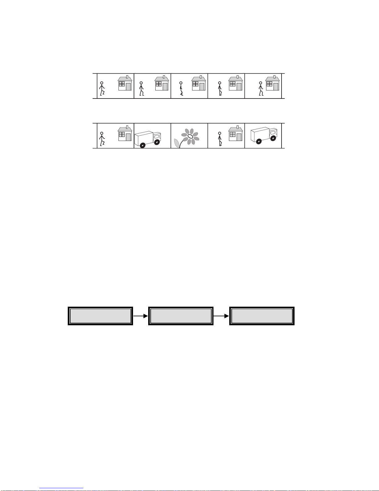
How Multiplexed Recording Works
To record several camera inputs on one video output, single images are digitally
captured from each of the video input channels and then stacked consecutively to
form a continuous video signal of time-sliced camera images. The time-slicing of
several inputs onto one output is generally known as Time Division Multiplexing
(TDM). Time base correction is performed during digital capture and so input
cameras need not be synchronised.
The order in which the images are captured from the different input cameras is
controlled by a user-programmed VCR record list (see page 31), which can be
automatically modified by the system in the event of alarms or motion detection.
Main Camera Enable
Page 32
HBZMXSIB/10/16SD-PR-1 Page 31
The multiplexed video fields can then be recorded onto a single VCR via the VCR
OUT connector.
Figure 8 Example of 3 Multiplexed Inputs
In addition to the video content sent to the VCR in each image, a packet of digital
data which uniquely identifies the field is inserted into each image sent to the VCR.
This packet data is not visible in the normal video and is used in the playback mode
to recognise the incoming fields and to link them back to the original camera input
from which they were captured. Besides the camera number, other status information
stored in this packet of digital data includes time and date, camera status, camera
title, time-lapse mode information as well as system and alarm status at the time of
recording. This status information, during playback, is reconstructed and displayed
with the corresponding camera. On playback, you can select one of several screen
formats for display and also choose which cameras to display, in which position in a
multi-screen display.
VCR Record List
You can program a Record List using the Menu System, which controls the sequence
in which the single fields from each camera are multiplexed to the VCR during
RECORD mode.
This list can consist of up to 30 camera numbers, in any order. This allows the same
camera number to be repeated in the list as required.
The list can contain any camera several times. For example, if the list is set to the
equivalent of “1 2 3 3 3 4 5 6 7 8 5__”, then camera 3 will be recorded once in the
record list cycle, but for three times the selected dwell time, and camera 5 will be
recorded twice in the cycle. For a multiplexer, the programming for camera 5 is the
preferred way to repeat a camera because it results in more evenly spaced updates
for that camera.
Trikcy BV
Trikcy BV
Camera 2 input
Cameras 1, 2 and 3 multiplexed to tape
2
2
3
2
1
2
2
2
3
2
Main Record
Record List
Page 33
HBZMXSIB/10/16SD-PR-1 Page 32
A blank entry ends the list. For example a list set to the equivalent of “1 2 3 _ 5 6 7 _”
will only record cameras 1, 2 and 3. The first ‘blank’ after the ‘3’ ends the list.
Automatic Modification Of The Record List
The multiplexer will automatically modify the list in the case of alarms and/or motion
detection, according to the modification parameters selected by you in the Alarm and
Motion Detection menus. For example, you can select ‘interleaved recording’ on
alarm. In this case, a camera in alarm will be recorded in virtual real time.
Note
If alarms and motion detection occur at the same time, the alarm’s modifications to
the record list will take precedence and will cancel all modifications made to the
record list via motion detection. Refer to the Alarm and Motion Detection sections
in this manual for more detail.
VCR Programming
Note
The multiplexer does not control the set up of the VCR itself. You must ensure that
the VCR is correctly programmed and has correct alarm inputs.
Unless the Vext input (see below) is used, it is important that the multiplexer is
programmed with the same record speeds as those to which the VCR has been set
for normal and alarm recording. The multiplexer programming menus provide a
simple interface for accomplishing this.
A VCR Camera Switch Input (or Vext) is also provided on the multiplexer, which
automatically adjusts the speeds to coincide with the VCR operation. In this case, the
multiplexer's recording speed need not be programmed.
Time-lapse VCRs are usually capable of dual speed operation, allowing two different
speeds of recording during normal operation and alarm situations. This allows faster
updates to be recorded in an alarm condition.
If the VCR switch input is not active, then the record speeds in the multiplexer menus
must match those set in the VCR.
The record speeds can be programmed in the Normal Record Speed and Alarm
Record Speed sections of the Record sub-menu. The factory default settings are 3
hour (NORMAL) and 3 hour (ALARM)
Main Record
Normal Record Speed
Alarm Record Speed
Page 34
HBZMXSIB/10/16SD-PR-1 Page 33
VCR Camera Switch Input (Vext)
Most time-lapse VCRs provide a hard-wired, pulse output to devices such as the
multiplexer, indicating that the VCR has just completed recording of one image of the
current camera. This lets the multiplexer know that it can switch to a new camera
input. This feature simplifies your installation since it automatically takes care of
synchronising the normal and alarm record speeds of the multiplexer with those of
the time lapse VCR. No VCR speeds then need to be set up in the multiplexer
menus, only on the VCR itself.
Provision is made for the VCR Camera Switch/Vext Input on the 25-way D-type
alarm connector on the rear panel of the multiplexer. An auto-detection circuit in the
multiplexer determines if this input is active, and automatically responds to it in the
RECORD mode, if the switch input detection is enabled in the menus.
The factory default setting is ENABLED, which allows the autodetection circuit to
operate. This is the recommended setting.
An on-screen R EXT indicator replaces the Record Speed indicator while this switch
input is active and detected by the multiplexer.
Note
On power up, the autodetection circuit will wait about 15 seconds to check if the
VCR starts to output a switch pulse. The period of 15 seconds is approximately
the period between switch pulses when the VCR is running in 960 hour mode.
During this brief time, the multiplexer will not switch cameras at all, unless a switch
pulse is detected. If the switch pulse ceases, the multiplexer will also take about
15 seconds to determine that it has in fact stopped and not just changed to 960
hour mode.
Switch Edge
The menus provide a selection for the pulse edge used for the Switch/Vext input. Do
not change this setting without first consulting Customer Support.
Monitor Outputs In Record Mode
MONITOR-A Output While Recording
On a duplex unit, you can select LIVE or PLAY mode while recording is taking place.
Hence you can select any desired Monitor-A multi-screen output on a duplex unit,
while multiplexed recording takes place on the VCR output. Monitor-A images can be
frozen.
On a simplex unit, Monitor-A only displays analogue, full-screen images while
RECORD mode is selected, and Monitor-B follows Monitor-A.
Main
V
CR Setup
Switch Input
ON/OFF
Main
V
CR Setup
Switch Edge
Page 35
HBZMXSIB/10/16SD-PR-1 Page 34
During recording, the multiplexer indicates the speed at which it is recording on
Monitor-A. It uses the same time-format for the indicator as is generally used by time
lapse VCRs. For example, R024 will be displayed to indicate that the unit is
Recording in 24 hour mode. If the VCR Switch Input is active, then R EXT will be
displayed.
On a simplex unit, this indicator will only be seen in RECORD mode. On a duplex
unit, this indicator will be visible in all modes.
Monitor-B Output While Recording
The Monitor-B monitor always displays analogue live, full-screen images of the
camera inputs, regardless of which mode is selected. The display can also
sequence.
Alarm Displays On Monitor B
The flashing indicator, ALM, is displayed in the live image for the camera in alarm.
On a simplex unit in RECORD mode, the Monitor-A and the Monitor-B outputs are
the same, and both will automatically switch to a full-screen live display of a camera
in alarm. Multiple simultaneous alarms cause the display to sequence between
alarmed cameras, with a fixed dwell time of 1 second.
Note
During RECORD mode, the alarm image on a simplex unit cannot be frozen on
Monitor-A.
Recording With Live Mode Selected On A Simplex Multiplexer
On the simplex unit, the unit’s VCR output during the LIVE mode is identical to the
Monitor-A, with the on-screen text present at that time. There will be no multiplexed
recording, and no digital data identifying each field.
On the duplex model, normal multiplexed recording can take place from the VCR
output even when LIVE mode is selected.
Record Mode Lock On A Simplex Multiplexer
This function does not apply to duplex models as they are always in RECORD mode.
On the simplex unit, it is often required that recording cannot be stopped by the
operator, either deliberately or in error. Recording will be stopped when switching to
LIVE or PLAY modes. To prevent recording being stopped, RECORD mode can be
locked ON in the menus, which are password protected. If power is lost to the unit
while RECORD mode is locked ON, then instead of powering up in the LIVE mode,
the unit will automatically revert to RECORD mode when power is restored.
Main Record
Record Mode Lock
Page 36
HBZMXSIB/10/16SD-PR-1 Page 35
VCR Type A / B
There are two basic types of time lapse VCRs. The multiplexer is designed to
operate with all commonly available time lapse VCRs (type A). There are some less
common VCRs (type B) which use a shorter interval between captured fields, which
can result in excessive duplication of cameras during normal recording.
Note
Do not change from type A to type B unless you have been advised to do so by
your supplier.
Live Video Display
To select LIVE mode, press the LIVE key .
The term ‘LIVE mode’ refers to the live Monitor-A digital displays, typically multiscreen displays of several cameras. The digital zoom and freeze can be used on
digital images.
In LIVE mode, Monitor-A displays multi-screen images of several cameras in formats
that you can select. Regardless of the mode selected, Monitor-B only displays live
analogue full-screen images of one camera at a time and so cannot be digitally
frozen or zoomed.
Live Mode - Monitor-A Displays
There are several different displays that you can select on the Monitor-A multi-screen
output during LIVE mode. These range from pics-in-pics (PIP) to a 4x4 display of 16
cameras (depending on the model) and full-screen for a selected camera.
If a multi-screen does not have all the cameras displayed, the system can sequence
all remaining cameras in the last cameo.
You can also select a full-screen digital display of any of the input cameras and a
sequenced display of full-screen cameras.
To select different Multi-screen displays press the MULTI-SCREEN key
on the
front panel.
Main
V
CR Setup
VCR Type A/B
Page 37
HBZMXSIB/10/16SD-PR-1 Page 36
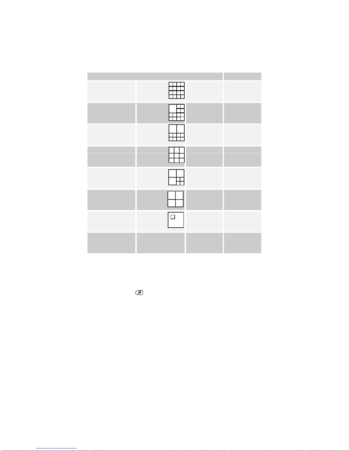
Each time the key is pressed, a new multi-screen format is selected. The order in
which the multi-screens will appear each time the MULTI-SCREEN key is pressed is
as follows:
Multi-screen Notes
16-WAY (4X4) 16-way
multiplexers
only
13-WAY (1X12) 16-way
multiplexers
only
10-WAY (2X8)
9-WAY (3X3)
7-WAY (3X4)
QUAD (2X2)
PIP (1 in 1)
16-WAY
(repeats from
top of list)
Sequencing In Cameos
Press the SEQUENCE key while in Live multi-screen mode to automatically
sequence all the undisplayed cameras in the lower right cameo. The cameo
sequence list cannot be edited.
Page 38
HBZMXSIB/10/16SD-PR-1 Page 37
Multi-Screen Dwell Time
The dwell time for sequences can be specified in the Sequencing sub-menu of the
menu system.
Automatic Camera Location Memory
If you have set up the camera numbers and locations which are to be displayed in a
particular multi-screen, then the unit will automatically save that selection and will
display the same camera selection and locations each time that particular multiscreen is selected. This is saved in volatile memory.
For example, if cameras 9, 4, 7 and 2 are selected for the quad multi-screen, then
whenever you select the quad multi-screen, those cameras will be displayed, and in
the same quadrants as you originally selected.
Automatic Multi-Screen Format Memory
If you switch from a multi-screen display to a full-screen camera image, then when
the MULTI-SCREEN key is next pressed, you will automatically return to the last
multi-screen format that was being viewed.
Set-up Of Cameras In Multi-Screen Displays
Any camera can be displayed in any position in the multiplexer multi-screen displays.
The default multi-screen displays show the cameras in ascending order. In LIVE
mode, you can display one camera in more than one position, while in PLAY mode
each camera can be displayed once only on each multi-screen.
To make it simple for you to select any camera for display in any cameo in a LIVE
multi-screen, the multiplexer uses the concept of Active Cameos.
Note
Active cameos are not allowed in a 16-way playback multi-screen on a 10-way
unit.
An active cameo is simply an on-screen indication of which particular cameo will be
affected by the next front panel keystroke. Active cameos are used mainly to give
you a simple way of specifying which camera is to be displayed in which cameo, but
other useful functions such as cameo freeze and zoom to full-screen are also
available.
An active cameo will only be present if you specifically select active cameo mode.
Press the ENTER key
while displaying any multi-screen. The top left cameo will be
the initial active cameo.
Main Sequencing Fullscreen Sequence List
Multiscreen Dwell
Fullscreen Dwell
Page 39
HBZMXSIB/10/16SD-PR-1 Page 38
The active cameo is indicated by flashing the camera number and its title. You can
use the ARROW keys to move to a particular cameo, and press a camera key to add
a camera to it. When a camera has been selected, the next cameo in the multiscreen becomes active. When you have finished, press the ENTER key
.
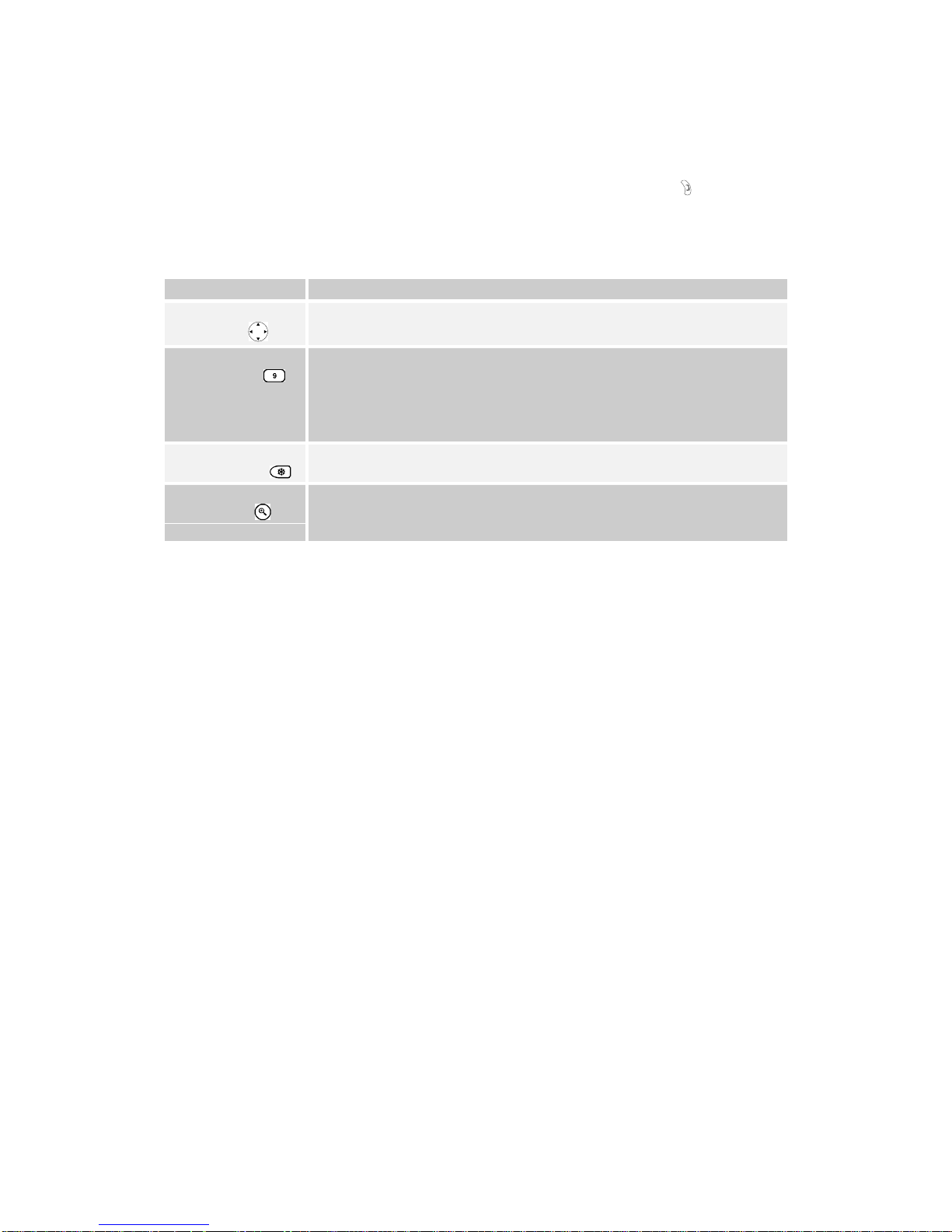
Key Functions During ACTIVE CAMEO Mode
Key Function
Arrow key
Moves the active cameo around the multi-screen.
Camera key Selects which camera to display in the active cameo.
The active cameo will then automatically advance to the next
logical cameo on the right so that you can easily enter camera
numbers in several cameos without using the arrow keys.
FREEZE key Freezes the cameo.
ZOOM key
Switches to a full-screen display of that camera. This will cancel
active cameo mode.
Notes
If the ZOOM key is pressed with no active cameo selected, then the display will
switch full-screen to the camera displayed in the top left cameo.
Live Mode - Full-Screen Displays On Monitor-A
Resolution of Full-screen displays (Colour models)
You can switch the resolution of digital full-screen displays from ‘frame’ displays to
‘field’ displays on Colour models. The lower resolution ‘field’ displays can result in
less ‘flickering’ on some high contrast camera scenes.
To switch between ‘field’ resolution and ‘frame’ resolution on a full-screen display,
press the camera number key of the camera which is already being displayed fullscreen. The display will toggle its resolution each time the key is pressed.
Note
This is a global system setting, not a camera-by-camera setting.
Field Or Frame Indication (Colour Models)
A minus sign (-) will be displayed next to the time / date display of camera 1 only to
indicate that ‘field’ resolution has been selected. The indicator is removed if ‘frame’
resolution has been selected.
Page 40
HBZMXSIB/10/16SD-PR-1 Page 39
Full-screen display
A full-screen display of any camera is selected on Monitor-A by pressing the
corresponding camera key.
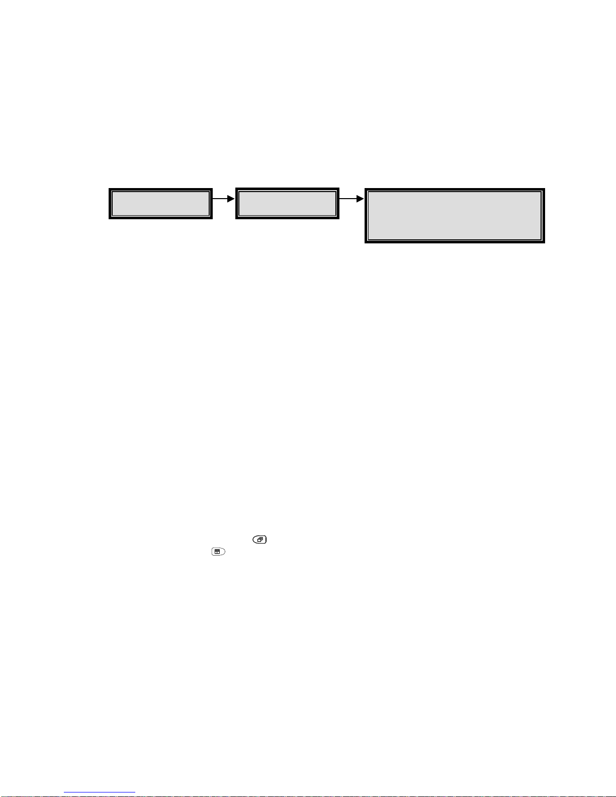
Full-Screen Sequence List
There is one full-screen sequence list which operates on both Monitor-A and MonitorB. The list has 30 entries.
The list is 30 entries long so that it can contain any camera several times. For
example, if the list is set to the equivalent of “1 2 3 3 3 4 5 6 7 8 5 __”, then camera 3
will be displayed once in the sequence cycle, but for three times the selected dwell
time, and camera 5 will be displayed twice in the sequence cycle.
A blank entry ends the list. For example a list set to the equivalent of “1 2 3 _ 5 6 7 _”
will only sequence between cameras 1, 2 and 3. The first ‘blank’ after the ‘3’ ends the
sequence list.
Factory Default
The default full-screen sequence list contains all cameras. This default list will display
each camera for the default dwell time of 3 seconds in each cycle.
Full Screen Sequencing On Monitor-A
Select any full screen display by pressing the camera number, and then press the
SEQUENCE key.
Pressing the SEQUENCE key
again, pressing any camera key, or pressing the
MULTI-SCREEN key
, will stop the sequence.
Live Mode - Monitor-B Displays
Monitor-B is a full-screen, live analogue display of the camera inputs. It displays only
full-screen, live images, regardless of the mode selected.
You can select a fixed display of any one camera on Monitor-B, or a sequenced
display of several cameras according to the full-screen sequence list specified by you
in the menus.
To operate on Monitor-B, the Monitor-B key must be pressed first. Text on Monitor-A
indicates that Monitor-B is selected. The LED in the Monitor-B key will light, and while
the LED is lit, any keys pressed will affect Monitor-B and not Monitor-A. Pressing the
Main
Sequencing
Fullscreen Sequence List
Multiscreen Dwell
Fullscreen Dwell
Page 41
HBZMXSIB/10/16SD-PR-1 Page 40
Monitor-B key again will switch off the LED and subsequent keys will operate on
Monitor-A.
Refer to the description of the full-screen sequence list above for Monitor-A (see
page 39). The same list is used for both Monitor-A and Monitor-B, and for LIVE and
PLAY modes.
Dwell Time
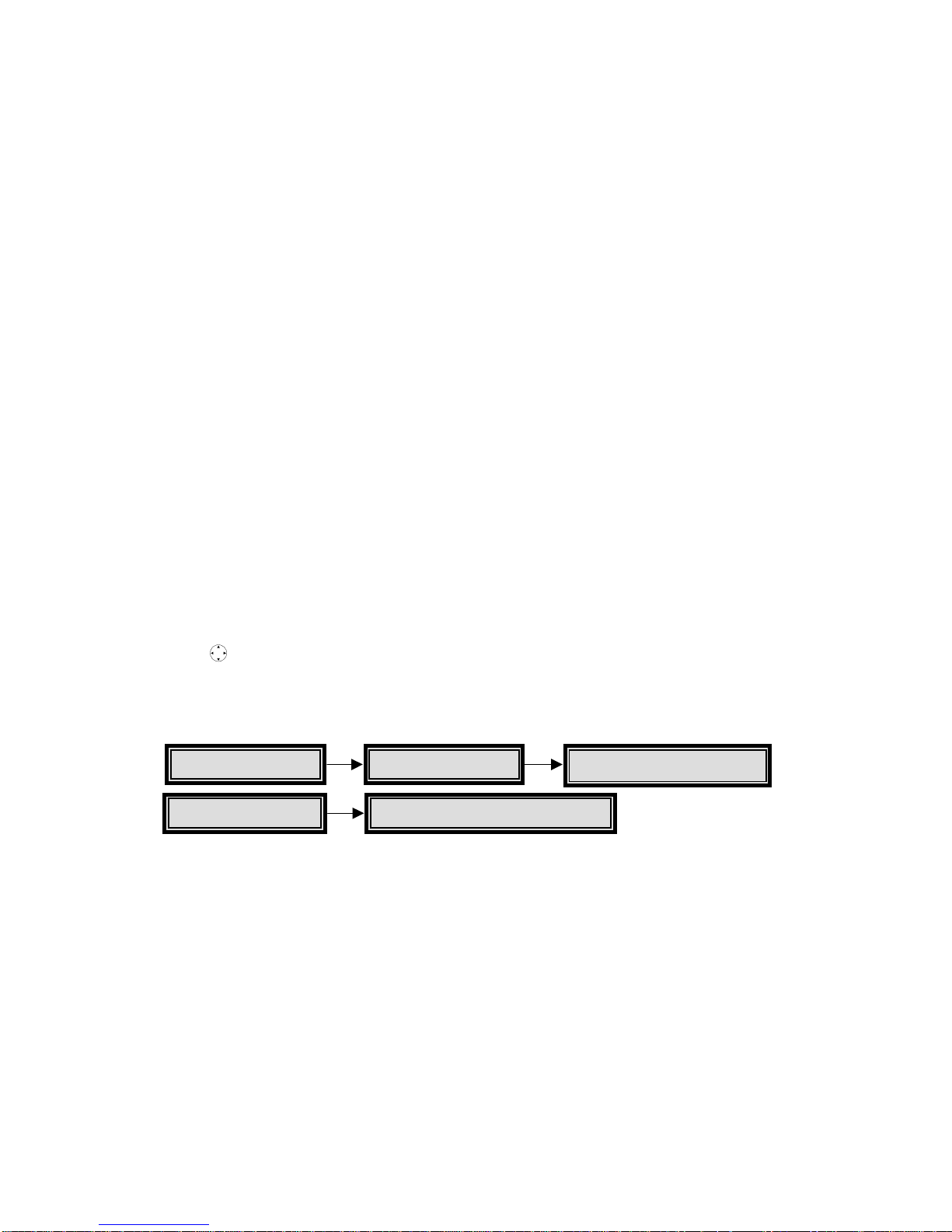
The full-screen, dwell time is set in the Sequencing sub-menu under the Full-Screen
Dwell option . The same dwell time is used for both Monitor-A and Monitor-B, and for
LIVE and PLAY modes.
PIP Display - Size And Position
The PIP (picture-in-picture) display on Monitor-A can be displayed in one of three
sizes (two for monochrome units in PLAY mode), and it can be displayed in one of
two positions.
The sizes can be 1/4, 1/9, or 1/16 of full-screen for Colour units, and 1/4 or 1/16 for
mono units in PLAY mode.
The PIP can either be displayed on the lower right hand side of the display, or else
on the top left hand side of the display.
Changing The PIP Size And Position In LIVE Mode
The PIP size and position can be changed during LIVE mode by using the arrow
keys
. The up and down arrow keys will change its position, and the left and right
arrows will change its size, left being smaller and right being larger.
Editing Titles, Changing Positions And Colours
To edit the camera titles, use the Camera Titles sub-menu in the menu. The factory
defaults show the camera titles as Camera 1 - Camera n.
Titles can be displayed either at the top or at the bottom of the camera view, or the
titles can be switched off. The titles can also be displayed as black, grey, or white
characters. This feature is selectable for each camera during either LIVE or PLAY
modes.
Select a full-screen view of that camera on Monitor-A, and then press ENTER to
toggle the title position and Colour. You can select one of seven options for each
camera.
Main Camera Titles
Edit Titles
Quick-Setup Edit Camera Titles
Page 42
HBZMXSIB/10/16SD-PR-1 Page 41
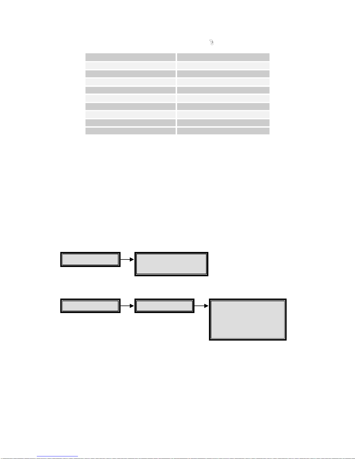
The following cycle will be followed as the ENTER key is pressed:
Position Colour
Top black
Top grey
Top white
Do not display this camera title
Bottom black
Bottom grey
Bottom white
Do not display this camera title
Top black (repeats from top of list)
Notes
This setting affects only the Monitor-A display. Text on the Monitor-B display is not
moved.
Note that the title display can be turned ON or OFF for each camera via the
Camera Titles sub-menu. This is effective in both LIVE and PLAY modes.
Editing The Time and Date, and Changing The Colours
To edit the time and date, use the Quick-Setup menu or the Time / Date sub-menu
from the Main menu.
Summer / Winter Time Change
Setting the time requires that you know the menu password. In some installations
personnel with access to the menus are not available to reset the unit’s clock during
time changes for summer and winter. The multiplexer provides a simple shortcut to
set time forward by an hour in spring and back by an hour in the fall, by using the
following Function key.
Main Time/Date
Time/Date display
Set Time Format
Set Date Format
Set Time
Set Date
Quick-Setup
Change the time
Change the date
Page 43

HBZMXSIB/10/16SD-PR-1 Page 42
To adjust the clock by an hour for Summer / Winter time changes press the
FUNCTION key
and then press the SEQUENCE key.
In March and April, this will cause the time to be adjusted forward by one hour.
In September and October, this will cause the time to be adjusted back by one hour.
This function can only be used once in each period. For example, if you press
FUNCTION + SEQUENCE during March, it will add an hour to the time. If
FUNCTION + SEQUENCE is pressed again, then it will be ignored until September.
When setting the date, select the correct day of the week, 1 to 7. For example, if
today’s date is set on a Wednesday and Sunday is day 1 in the week, then enter a ‘4’
during date set-up. This is used to start Timed Macros on the correct day.
The time can be in one of two formats, and the date can be in one of three formats.
The time format can be either to a 12 hour or 24 hour clock. The date format can be
either DD/MM/YY, MM/DD/YY, or YY/MM/DD.
To change time and date Colour on Monitor-A, select camera 1 full-screen, and
toggle its title position and Colour as described on page 40. Each time the cycle is
completed for camera 1, the time/date Colour will be toggled to a new Colour. This
time/date Colour setting is a global system setting.
When the time/date Colour has been selected, toggle the camera 1 title position and
Colour to its desired state.
Note
The time/date display can be turned OFF for either MON-A or MON-B in the menu
system, using the Time/Date sub-menu. The MON-A setting is effective in both
LIVE and PLAY modes.
Page 44

HBZMXSIB/10/16SD-PR-1 Page 43
Playback
To enter PLAY mode, press the PLAY mode key .
When playback is first started, the unit will automatically select a multi-screen display
on Monitor-A, which can show all the cameras which were recorded on that tape.
PLAY mode will always stop any LIVE mode multi-screen displays on Monitor-A.
Note
On the simplex multiplexers, PLAY mode will also cause RECORD mode to stop.
Your video multiplexer can display video played back from a VCR whether it was
originally recorded from a valid multiplexer, or whether it was recorded off a normal
video input, i.e. not multiplexed. Tapes that were not recorded on a multiplexer will
automatically be played back without attempting to separate the fields.
The multiplexer can also correctly interpret tapes encoded on Dedicated Micros
multiplexers, by changing a user-selectable option in the menu system. This is useful
in installations which already have other multiplexers in use (see Decoding Tape
Formats From Different Multiplexers, page 44.
On playback, you can select one of several multi-screens on Monitor-A to display the
recorded images which are being played back from the VCR. During playback, all onscreen text on Monitor-A will show the status, time and date at the time of recording.
Monitor-B will always display live analogue signals. No playback images are shown
on Monitor-B. During playback, the text LIVE is displayed on Monitor-B so that you
can clearly see that the signal on Monitor-B is live, while that on Monitor-A is a
playback signal.
How Playback Works
When playing back multiplexed recordings which were originally recorded from a
multiplexer, time-stamped video fields are received from a VCR connected to the
VCR IN connector or YC input on the multiplexer’s rear panel, each field being
uniquely identified by its own digital data packet. These embedded digital data
packets are decoded, and the video field is linked to its original input camera. You
can select which cameras to display during playback, and so the video field for that
camera is displayed (or skipped) according to your playback selection. All the
associated status information, including titles, time and date of recording, as well as
the alarm or video loss status of the camera is reconstructed from the digital data
packet and displayed as on-screen text during playback. Because the on-screen text
is re-constructed and generated for on-screen display (as opposed to being recorded
on the VCR as part of the video display) you are assured of very clear and legible
status and titles during playback.
Page 45
HBZMXSIB/10/16SD-PR-1 Page 44
Setting The VCR Playback Speed
You must select the playback speed on the VCR, and not on the multiplexer. There is
no related set-up required on the multiplexer during playback.
The multiplexer will automatically adjust its display to match the VCR playback
speed.
Indicators
The on-screen indicator (P024 for example, for 24 hour mode) tells you the speed at
which the tape was recorded. It does not indicate the speed at which the tape is
being played back. To find out the playback speed, you must look at the VCR’s
playback speed indicator.
The multiplexer will display the text N/A if a camera does not get updated from tape
within a minimum time (N/A signifies that the camera is Not Available). This is a
warning message, not an error message. This indicator warns you that the update
rate is very slow or updating may have stopped. It warns that there may have been
events that were not captured during the recording, or the tape data may be
corrupted.
Decoding Tape Formats From Different Multiplexers
Your multiplexer can decode tapes recorded on other multiplexers. If a tape from a
DM compatible multiplexer is to be played back, the Alternate format must first be
selected from the menu system.
Tapes Recorded On A Compatible System
The unit must be set to Default format in the Playback Format sub-menu to decode
tapes recorded in Baxall ZMX format. This is the factory default setting.
Tapes Recorded On A Dedicated Micros Compatible System
To decode these tapes, select the Alternate option. When play is selected, an onscreen ‘ALT’ indicator will indicate that DM Compatible decoding is in progress.
During DM tape decoding, the multi-screen formats can be selected exactly as for the
normal multiplexer tape playback.
Note
If DM (Alternate) decoding is currently selected, tapes made via your multiplexer
will not be correctly decoded, and vice-versa.
Main
Default
Alternate
Playback Format
Page 46

HBZMXSIB/10/16SD-PR-1 Page 45
PLAY Mode - Monitor-A Displays
Monitor-A Multi-Screen Display Formats
When playback is first started, the unit will automatically select a multi-screen
display on Monitor-A, which can show all cameras which were recorded on that tape.
To select a different multi-screen, press the MULTI-SCREEN key
. To select
different cameras in a multi-screen, use active cameo set-up (see page 37).
During PLAY mode, you can select the multi-screen formats which are available in
LIVE mode, except for PIP, 7-way, 10-way and 13-way displays on the mono units,
and except for 7-way and 13-way displays on the colour units (see page 35)
Full-Screen Displays
To select a camera for full-screen playback on Monitor-A during the PLAY mode,
push the corresponding camera key once. A full-screen display of that camera from
tape will be displayed full-screen.
When Tapes Cannot Be Decoded
If the multiplexer cannot decode a tape which is being played back, the system will
display a blank screen. The fields will not be decoded or separated.
There are two possible reasons why a tape cannot be decoded:
1) the tape was not recorded on a multiplexer, or
2) the tape is not compatible with the decoding format you have selected.
In the event that the tape was actually recorded on either a compatible multiplexer or
a DM multiplexer, but is not correctly decoded, first check to see that the correct
Playback Format has been selected in the menu system.
With the VCR playing back, press the FUNCTION then the PLAY mode key
to
view the undecoded input.
The time and date are displayed on-screen during PLAY mode. You should note,
however, that this is the recorded time, not the current system time.
The indicator, V, in a multi-screen and VDL, in a full-screen, will be displayed in the
corresponding camera image if there was video loss at the time that the recording
was made.
Note
Any camera which is not detected on tape for 8 or more consecutive cycles during
playback, and is not flagged as a video loss camera, will result in the warning
message, N/A, signifying that it is Not Available. This is a warning message only.
Page 47

HBZMXSIB/10/16SD-PR-1 Page 46
Several circumstances can cause an N/A indication. These are:
1) The camera may not have been included in the record list at the time of
recording.
2) The camera may have been disabled at the time of recording.
3) The images for that camera on tape have been corrupted and cannot be
decoded at time of playback.
4) The VCR play speed is very slow.
The N/A indicator helps you to tell the difference between images which are not
being updated during playback and images which are being updated from tape but
have no movement within the image.
The indicator, A, will be displayed with the corresponding camera image on MonitorA if there was an active alarm at the time that the recording was made.
There is no indication on-screen to show that the unit is decoding in the multiplexer’s
compatible format, because this is the unit’s native mode.
Caution
The Monitor-B time and date, alarm, videoloss, titles and all other on-screen data
and indications will be related to the current, live data, and must not be confused
with the playback data which is being displayed on Monitor-A.
Play Mode - Changing Text Positions And Colours
The positions and colours of camera titles, and the colour of the date / time can be
set separately for playback.
PLAY Mode - Sequencing During Playback.
During PLAY mode, the multi-screens and full-screens can be sequenced according
to the sequence list and dwell times programmed in the menu system.
Caution
This option must be used with caution if the VCR is set to time-lapse speeds while
playing back.
When sequencing the display during playback, do not set the VCR’s play speed
such that the frequency at which any one camera is played back off the tape is
slower than the frequency that the sequence list will switch through cameras in the
list.
Recommendation
Set the VCR to its normal speed (3 hour for PAL) when sequencing displays
during playback.
Page 48
HBZMXSIB/10/16SD-PR-1 Page 47
Alarms
The multiplexer is equipped with one alarm input per camera input, each of which is
normally associated with its corresponding camera input. An active alarm input can
result in an on-screen indication on both Monitor-A and Monitor-B, a flashing front
panel LED, an internal buzzer and automatic modification of the record list to give the
camera in alarm a higher update rate.
Two isolated alarm output relays are provided. One relay can be activated by any
alarm input, and the other by video-loss or by activity detection.
The alarm inputs are configured as zero potential relay contacts, individually
programmable via the menu to be normally open (NO) or normally closed (NC). To
select the alarm input configuration as NO or NC, use the Input Configuration section
of the ALARM sub-menu. The factory default is NO.
During alarms, the multiplexer can automatically adjust the record list so that any
cameras in alarm are recorded at a higher rate, according to your selections.
Alarm inputs, if not used, should be set as N/O.
Alarm Handling Capability
Alarms will result in an automatic full-screen image of the camera in alarm on
Monitor-A and Monitor-B. The alarms can activate an output relay. The alarms can
be latched until accepted by the operator, or latched for a preset time, or follow the
status of the alarm input. The alarm latching is a system-wide setting, selectable by
you.
Simple menu tables make it quick and easy for the you to select the desired alarm
action.
Alarm Displays In Live Mode
During alarms in LIVE mode, Monitor-A will automatically switch to a full-screen
display of the camera in alarm. If multiple alarms are active, Monitor-A an B will
automatically sequence between the alarm cameras at a fixed 1 second dwell. This
dwell is not programmable.
You can freeze the camera in alarm on Monitor-A by pressing the FREEZE key
.
Note
The Monitor-B screen will not revert to its original fixed display after the alarm is
cleared. It will continue to display the last alarm camera. However, if sequencing
was active on Monitor-B before the alarm, then Monitor-B will continue to
sequence after the alarm is cleared.
Main
A
larms Input Configuration
Main Camera Titles
Alarm latch
Page 49
HBZMXSIB/10/16SD-PR-1 Page 48
Alarm Displays In Play Mode
Regardless of the mode selected, Monitor-B will always display live images. Hence,
during PLAY mode, live alarm inputs will cause live alarm displays on Monitor-B, not
Monitor-A. Monitor-A will continue to display playback images.
Monitor-A During PLAY Mode - Recorded Alarms
In PLAY mode the Monitor-A display will not automatically provide alarm displays
based on recorded alarm status. Monitor-A will display the playback images from the
VCR according to your selected formats, and will display the normal A alarm
indicator only if a camera was in alarm at the time that a recording was made.
Caution
If a camera which had an alarm at the time of recording is not selected by you for
display, there will be no on-screen indication at all that the alarm occurred. Thus if
you are looking for cameras in alarm during playback, ensure that all the cameras
on tape are displayed by using a 16-way multi-screen.
Alarm LED And Internal Buzzer In PLAY Mode
The LED and internal buzzer alarm indicators will be activated only if a live alarm is
active. Alarm status played back from a recorded tape has no effect on these
indicators. The internal buzzer can be disabled via an internal hardware strap.
Alarm Displays In Record Mode, Simplex Models Only
During RECORD mode only, and on the simplex model only, Monitor-A displays are
always analogue full-screen, exactly the same as Monitor-B’s normal mode.
As a result, the simplex model cannot display a multi-screen image on Monitor-A
during recording, and alarms cannot be manually frozen. If an alarm occurs during
RECORD mode, Monitor-A will automatically switch to the live analogue full-screen
display of the camera in alarm. If multiple alarms are active while recording, the
simplex unit will automatically sequence between the alarm cameras at a fixed one
second dwell. This is exactly the same display as on Monitor-B during alarms.
Recording For Alarms
You can select either Normal recording, Exclusive recording or Interleaved recording
to take place whenever an alarm occurs. The latter two modes will always result in a
faster update to tape of a camera in alarm.
Note
This is a global setting, and is not set up individually for each alarm input.
Main Record
Alarm Record Speed
Page 50

HBZMXSIB/10/16SD-PR-1 Page 49
To select the recording rate during alarms, choose the Alarm Record Speed option in
the Record sub-menu.
Normal
Normal recording during alarms means that there is no priority recording for the
cameras in alarm, and the record list will be unchanged while alarms are active.
However, you can still program the VCR and the unit to switch from a time-lapse
speed to a faster recording speed during alarms, which by itself can ensure that
alarm events have a faster update speed.
Exclusive
Exclusive recording will cause the system to record only alarmed cameras. All nonalarmed cameras are omitted from the record list while an alarm is active. Exclusive
recording mode is typically chosen only when several simultaneous alarms can be
expected to occur very often, and where near real-time records of those alarm events
are needed. The disadvantage of choosing this mode is that events on non-alarm
cameras will not be recorded at all while any alarm is active.
If real-time recording of single alarms is required on mono models, select Exclusive
recording. However, bear in mind the disadvantage of selecting this mode.
Note
On colour models, which have PVP, if only one camera is in alarm and the alarm
speed is set to 3-hour mode, then the unit will automatically select Interleaved
recording, even though Exclusive mode is selected. This is because the fast
update will still result in a real-time update of the camera-in-alarm during
interleaved recording at 3-hour recording speeds.
Interleaved
During interleaved recording, both the alarmed cameras and non-alarmed cameras
are recorded, but the alarmed cameras, having a higher priority, are interleaved
between non-alarmed cameras.
Interleaved mode offers increased recording of cameras in alarm, without stopping
the recording of other cameras. This is the mode recommended for most
installations.
Example
Non-alarmed cameras: 1,2,3,5,7
Cameras in alarm: 4,6
Interleaved recording sequence: 1,4,6,2,4,6,3,4,6,4,4,6,5,4,6,6,4,6,7,4,1,
..etc.
Page 51
HBZMXSIB/10/16SD-PR-1 Page 50
Note
Because of the fast update rate of the colour units, if one camera is in alarm,
interleaved mode will result in real-time playback of the camera in alarm. In
general, on the colour units, interleaved recording will give very fast update
speeds of cameras in alarm even for multiple alarms. This is not the case for the
mono units, which do not have fast PVP recording at alarm speeds.
Alarm Indicators
There is an on-screen display of an A in each corresponding cameo of multi-screen
displays and ALM, on any full-screen displays relating to cameras in alarm. The
indications will be flashing.
An additional indication, in the form of an LED, is provided on the front panel, under
the ALARM key
. The left hand LED will flash if any live alarm is active and has
not been cleared.
An internal buzzer can sound while any live alarm is active. This buzzer can be
silenced by pressing the ALARM key or if required, disabled.
Alarm Latching
There are three ways of latching alarms, which may be selected via the menu. These
are:
1) Latched until the operator cancels it (Latched).
2) Not latched (Transparent).
3) Latched for a pre-set time (Timed Out).
To set the type of latching, select Alarm Latch in the Alarms sub-menu. All the alarm
inputs are controlled by this single setting.
Latched Alarms
Alarms are latched as they become active. An alarm will stay active until the operator
acknowledges it by pressing the ALARM key
. There is no time-out period.
When the operator acknowledges the alarm, it will be cleared, whether the alarm
input is still active or not.
Timed out alarms are latched for a pre-set time out period from the start of the alarm
becoming active. After expiry of the time out period, the alarm is automatically
cleared unless the alarm input is still active and then it will clear immediately after the
alarm input ceases. Alarms that cease and restart before the time out is complete,
will restart the time out period.. The time out period is programmable in the menu
system.
Main
A
larms
Alarm Latch
Page 52
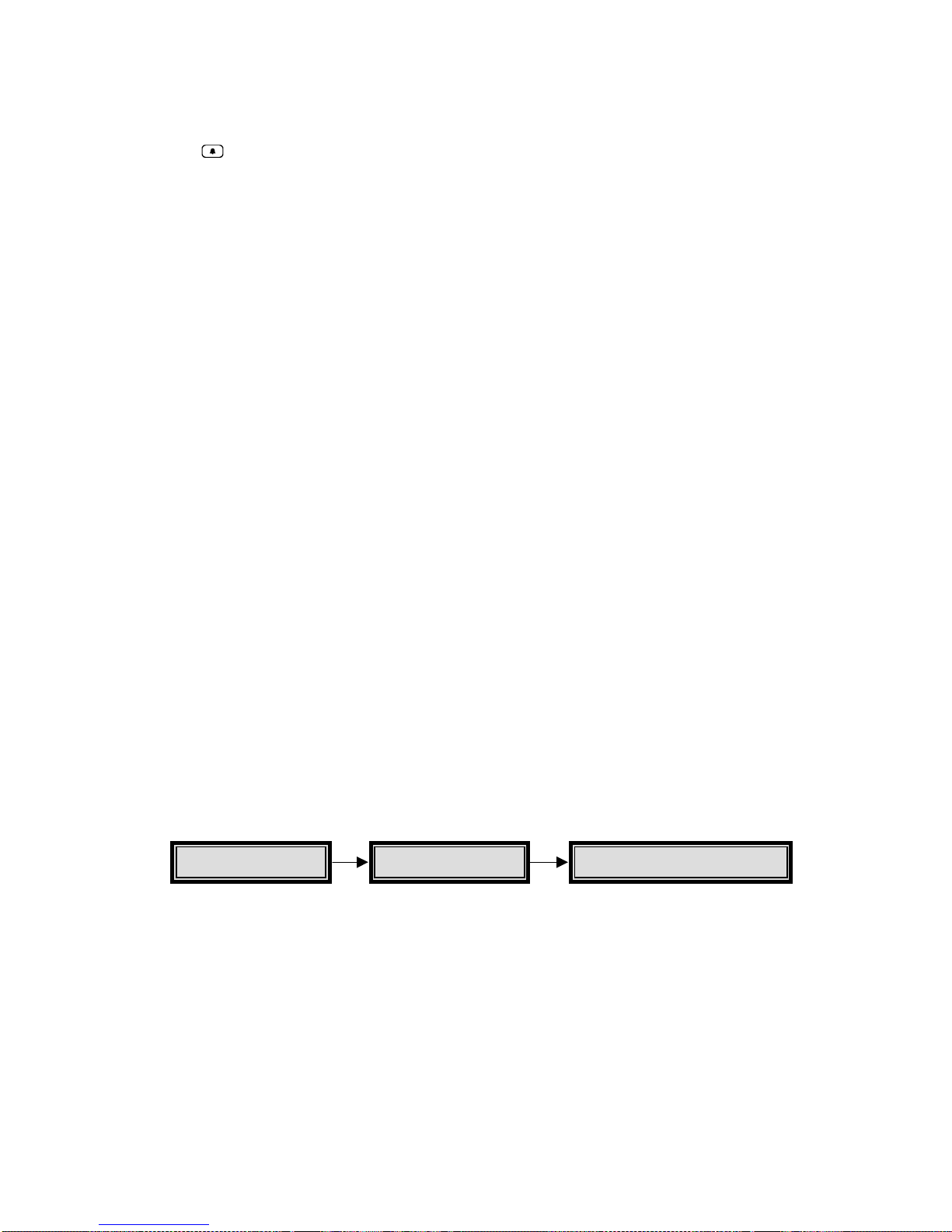
HBZMXSIB/10/16SD-PR-1 Page 51
Timed out alarms can be cleared by the operator at any time by pressing the ALARM
key
. Like latched alarms, if the operator cancels the alarm, it will be cleared
whether the alarm input is still active or not. Alarms that are cleared by the operator
before their inputs have ceased, will not be reactivated until the alarm input ceases
and restarts.
Alarms are active only while the alarm input is active. As soon as the alarm input
ceases, the alarm will be automatically cleared. A Transparent alarm cannot be
cleared by the operator, it will remain active as long as the corresponding alarm input
is active.
Application Note
If it is necessary for the operator to be able to clear active alarms, and
Transparent mode is preferred, then select timed-out alarms instead of
transparent alarms in the Alarm Latching sub-menu, and set the time-out period to
one second.
Alarms that have been acknowledged by the operator will not be reactivated unless
the alarm input has ceased and then restarts.
Alarm Outputs
Two outputs are provided to enable you to program automatic external actions such
as a speed change on the VCR, or alarm lights or sirens. The relay outputs are rated
at 30v 500 mA. Alarms always activate Relay 1.
They are provided in both the normally open (NO) and normally closed (NC)
configuration on the rear panel of the unit.
The alarm outputs can be activated by motion detection, by active alarms, by
videoloss, or by Macro functions.
The multiplexer also allows you to read the status of the alarm inputs for each
camera via the RS-232 remote control port.
Alarm History
An alarm history is kept in a cyclic buffer. History data, including the camera number,
time and date are kept in memory for up to 100 events. The most recent 100 alarm
events can be viewed on-screen in the menu system, by selecting the Alarms menu
and then selecting Alarm History.
A table will appear, allowing you to browse forward and backwards among the last
100 alarmed events.
The RS-232 remote control capability allows an operator to upload the alarm history
to a PC or a similar controlling device.
Main
A
larms
Alarm History
Page 53
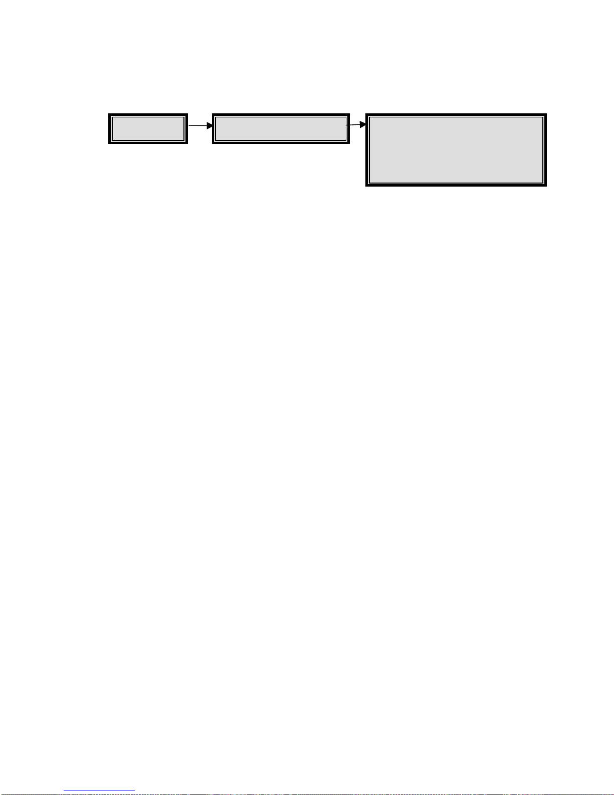
HBZMXSIB/10/16SD-PR-1 Page 52
Motion Detection
The multiplexer offers comprehensive motion detection capabilities, including
sensitivity settings and detection area selection per camera. Motion detection is used
to adjust the rate at which cameras are recorded.
The motion detection provided on these multiplexers is not intended for intrusion
detection, only for activity detection.
Activity Detection
Activity detection simply looks for changes in the luminance in various selected areas
of the screen, and if changes are above a set threshold then the activity detector
interprets that to be activity. Changes in light and camera vibration can also be
falsely interpreted as activity. This method is used in the ‘motion detection’ offered by
most multiplexers, and is adequate to detect activity in a scene.
Extensive Setup Capabilities
Motion detection can be enabled or disabled individually on each camera, or on all
cameras.
Motion detection can be set up separately for each camera via the menus. The
motion detector uses a detection grid of 256 zones per camera. Each zone consists
of many detection points, averaged over the zone. The zones can be individually
enabled or disabled, so that some parts of the camera view can detect motion and
other parts can ignore motion. You can select one of 10 levels of sensitivity for each
camera to compensate for contrast and lighting conditions.
The set up has been made as uncomplicated and easy as possible. A menu structure
with an on-screen grid and set up prompts is used to simplify set up.
Automatic Record List Modification
With motion detection, it is possible to automatically record cameras with motion at a
higher rate than cameras which have little or no motion. This is the most common
use of motion detection in multiplexers, and requires only activity detection. The unit
automatically inserts a camera into the record list more often whenever activity is
detected, so that the cameras with more activity are recorded at a higher rate. The
multiplexer offers advanced set up for the Record List modification: The rate of
increase can be set by you in the menus so that cameras with activity can be
recorded twice as often as normal, or four times as often, or they can be interleaved.
Enable/Disable Detection
Setup Active Zones
Indicate Detection
Setup Parameters
Main Motion Detection
Page 54
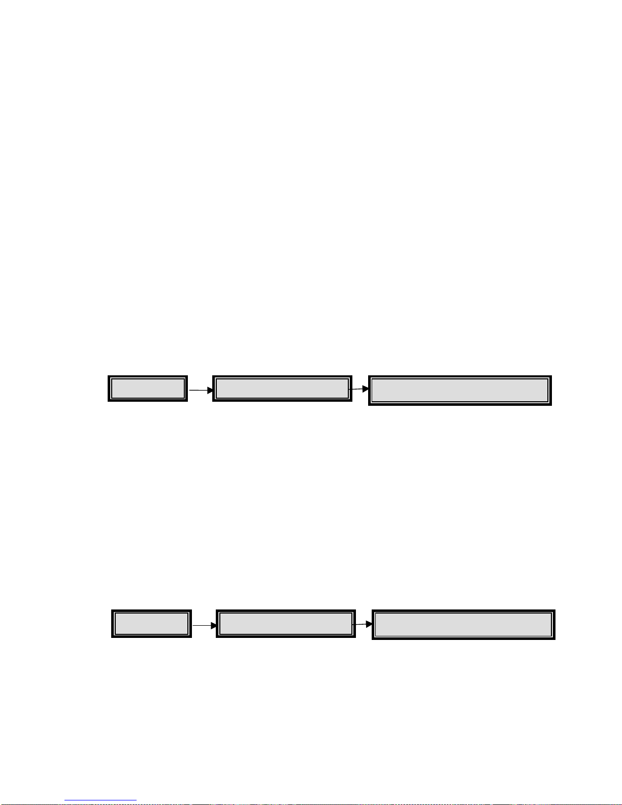
HBZMXSIB/10/16SD-PR-1 Page 53
Programmable Outputs
You can select one or both of the two output relays to be activated when motion is
detected. This can be set up separately in the menu system for each camera.
Motion Indicators
The indicator, M, will appear in each camera scene on Monitor-A whenever motion
has been detected. The indicator is not present on full-screen analogue displays.
This motion indicator will stay on each active camera’s display for at least 2 seconds
after the motion has ceased. The motion indicator can be turned on and off in the
menu system, via the Indicate Detection section of The Motion Detection menu.
The default setting is off.
Note
The primary purpose of the multiplexer is efficient video multiplexing and the alarm
handling and motion detection are secondary functions. National standards
relating to alarm equipment should be taken into account when choosing
equipment to use with the multiplexers, and in general the multiplexer should not
be the only alarm device on the site.
Setup - Enabling And Disabling Motion Detection On A Camera
The factory default setting is each camera has motion detection disabled when the
unit is first powered up.
The first action which should be taken by you with respect to motion detection during
installation, is to enable the cameras on which activity detection is desired. For
verification, turn on the ‘M’ indicator.
If motion has been turned on, but there is no M indication in the corresponding
camera’s display during motion on that camera, first check that the indicator display
is correctly turned on in the Indicate Detection option of the Motion Detector submenu. If motion is still not detected, check the set up of the detection zones and the
sensitivity setting as detailed in sections Setup - Enabling And Disabling Detection
Zones and Setup - Setting Sensitivity respectively.
Setup - Enabling And Disabling Detection Zones
The 256 zones are arranged in a 16 x 16 grid. Each zone can be enabled or disabled
by you, via the menu system. The factory default is that all zones are enabled. Note,
however, that all cameras have motion disabled as detailed on page 52. This must
not be confused with enabling or disabling individual zones within the camera scene.
During set up, use the menu system to disable zones which may contain movement
that is incidental or not important. Incidental motion can include the possible
Main Motion Detection Enable/Disable Detection
Main Motion Detection
Setup Active Zones
Page 55
HBZMXSIB/10/16SD-PR-1 Page 54
movement of trees in the wind, vehicles in an adjacent street, allowable pedestrian
areas, or areas with glass and other highly reflective surfaces which can be sources
of apparent motion via reflections.
To enable or disable zones, select Setup Active Zones from the Motion Detection
sub-menu. A new menu will prompt you to select a camera. The camera number can
be selected using either the arrow keys
, or the camera keys. The title will also be
displayed for information purposes only - it cannot be edited in this particular menu.
After selecting the camera which is to be set up, the system will switch Monitor-A to
the camera chosen and will then draw a 16 x 16 grid over the camera view. Each
block in the grid is one of the 256 zones.
Cursor
The top left zone will have a flashing square indicator p, known as the cursor. The
zone which has the flashing cursor can be enabled or disabled. When the cursor
reaches the end of a line in the zone grid, it will automatically wrap around to the
beginning of the next line.
Use the ALARM key
to select either the enable or disable mode, and then use the
ARROW keys
to ‘paint’ the adjacent zones with the mode selected.
The ALARM key
toggles between three possible zone set up modes, and the
cursor will change colour as shown below:
Mode Cursor colour
No Action grey/white
Enable Zones black/white
Disable Zones clear/white
The on-screen prompts shown during the zone set up are as follows:
ALM: NO ACTION ENTER TO EXIT
As you press the ALARM key
, you change the action from NO ACTION to
ENABLE to DISABLE and back to NO ACTION. Press the ENTER key
exit.
The NO ACTION set up mode is used to get the cursor to a part of the grid where
zones must be changed to enabled or disabled. This is normally used if only a small
part of the grid needs to change. After selecting no action by using the ALARM key
, use the arrow keys to go to the first zone to be changed.
Page 56
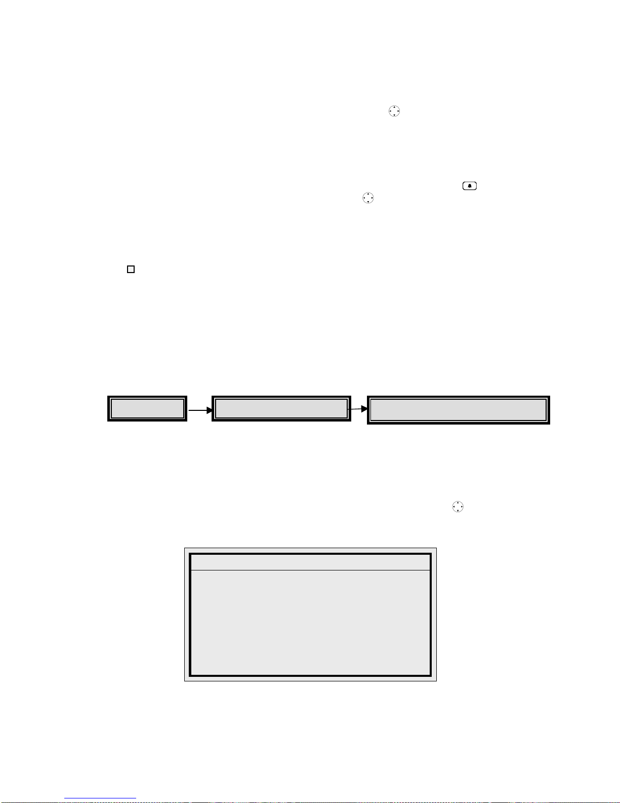
HBZMXSIB/10/16SD-PR-1 Page 55
The ENABLE set up mode is used to change disabled zones to enabled zones.
Enabled zones will sense motion, according to the sensitivity and the minimum target
size set for the camera. When this mode is selected, the zone which has the flashing
cursor will be changed to an enabled zone. The arrow keys
can be used to move
the cursor and enable as many other adjacent zones as necessary. Change the
mode to NO ACTION or DISABLE when no more adjacent zones need to be
changed.
The DISABLE set up mode is used to change enabled zones to disabled zones.
Zones which are disabled will ignore all motion. After using the ALARM key
to
select the DISABLE mode, the cursor and arrow keys
can be used to disable as
many adjacent zones as necessary, exactly as was described above to ENABLE
zones.
Indications
To indicate whether each zone is enabled or disabled, enabled zones have a grey
“ ” indication and disabled zones have no indication inside the corresponding
grid position.
Press ENTER to exit the zone set up screen, and return to the Motion Detection
menu. All the changes will be saved as they are made. In the Motion Detection submenu, you can then set up sensitivity for the same camera, or zones can be set up
for a different camera.
Setup - The Motion Parameters Menu
The three motion parameters, sensitivity, automatic increase in record rate on
motion, and output relays, are all chosen in a single menu table on a camera-bycamera basis.
Select the Setup Parameters section of the Motion Detection sub-menu to set any of
these parameters. The Motion Detection Setup, Select Camera window will appear,
where you select the camera. Select the camera by using the arrow keys
and
pressing enter. This will display the activity parameters for the selected camera. For
example:
The Camera field displays the number of the selected camera and cannot be
changed. The Sensitivity, Record Rate and Relay fields are described below.
A
ctivity Parameters Setup
Camera : 01
Sensitivity : 06
Record Rate : 4x
Relay Output : NONE
[CANCEL] [OK]
Main Motion Detection
Setup Parameters
Page 57

HBZMXSIB/10/16SD-PR-1 Page 56
Setup - Setting Sensitivity
The motion detection on each camera can be set to one of 10 levels of sensitivity to
movement. The sensitivity setting is set on a camera-by-camera basis, and applies to
all the zones in any particular camera scene.
Each zone stores 256 grey levels of discrimination, averaged over the zone’s area.
The sensitivity to change in a zone can be set to the most sensitive by selecting a
sensitivity of 10, and to the least sensitive by selecting a sensitivity of 1.
A sensitivity of 10 will detect a change of 5 grey levels in a zone, averaged over the
zone. A sensitivity of 1 will detect changes of 100 grey levels or more within a zone,
averaged over the zone. The factory default sensitivity is 5, for all cameras.
To set the sensitivity for any camera, select Setup Parameters from the Motion
Detection sub-menu.
Recommendations
When setting or adjusting sensitivity, choose the highest setting that does not result
in very frequent ‘false’ motion settings. The higher the sensitivity, the more likely it is
that incidental movement will be detected as motion. If motion is indicated without
apparent cause, reduce the sensitivity.
Record Rate
Your multiplexer shares one VCR between many cameras. As a result, the video
from a camera which normally provides 50 fields a second, must be time sliced and
reduced to a rate of far fewer fields every second. This allows the other cameras to
insert fields into the same video stream going to the VCR. The lowered update rate
for each camera is not a problem if there is little movement in the scene. If, however,
there is activity in the camera view, it is always preferable to get as many updated
fields of the activity as possible, so that important activity events are recorded.
Your multiplexer solves this dilemma in two ways:
1) It has a very fast, optimised update rate to tape .
2) It allows the rate of update of each camera to tape to be automatically
adjusted by the system if there is ongoing motion within a camera’s field of
view. In this way, cameras without activity are recorded less often and
cameras with frequent and continuous activity are recorded more often and so
can capture more of the activity.
A unique feature of your multiplexer is that the increase in update rate can be set by
you in the menu system. Cameras with activity can be recorded at the same rate, or
twice or four times as often as they would normally be recorded, or they can be
interleaved. This allows you the flexibility to set up the system according to the
requirements of the particular installation.
Note
The record list and record rate can also be modified by an active alarm. A record
list update resulting from an active alarm input will always override any record list
modifications which resulted from sensing activity.
Page 58

HBZMXSIB/10/16SD-PR-1 Page 57
To set the record rate increase during activity, select the Setup Parameters option of
the Motion Detection sub-menu. There are four choices of Record Rate increase for
activity:
NO CHANGE
2 X
4 X
I (Interleaved)
The first choice, NO CHANGE, is usually chosen only if most cameras are expected
to have motion at the same time. Interleaved is normally chosen only if very few
cameras will have motion at any one time. A setting of 2x may be optimal if not all the
cameras are connected, and on the 10 Way models. The factory default setting is 4x
for all cameras.
Relay Output
Two relay outputs are provided to enable you to program automatic external actions
such as a speed change on the VCR, or alarm floodlights or sirens.
The relay outputs are rated at 30v 500 mA. They are provided in both the normally
open (NO) and normally closed (NC) configuration on the rear panel of the unit, and
are isolated.
The two outputs can be activated by activity detection, by active alarms, by video
loss, or by Macro functions. The choice of which output is activated by which event is
selectable via the menu system on a camera-by-camera basis.
Selecting the Relay Outputs
Select the Setup Parameters section of the Motion Detection sub-menu.
In the Relay Output field, you have the following four choices for each camera:
NONE
1
2
1+2
The factory default setting for Alarm Output Relays is as follows:
All Alarm Inputs will activate Relay 1
All Activity Detection will activate Relay 2
All Video Losswill activate None
Page 59

HBZMXSIB/10/16SD-PR-1 Page 58
Special Functions
Videoloss
You get the indication, V, displayed in each affected cameo of the multi-screen
display and VDL on any corresponding, full-screen displays.
You can select an output to be closed whenever video loss is present, and can turn
the buzzer on and off during video loss, as follows:
1) Select the Videoloss Action sub-menu.
2) Select the Camera for set up.
3) In each output field, ENABLE or DISABLE the corresponding relay.
4) In the Buzzer field, select ENABLE or DISABLE.
Monitor-A: If the camera is being displayed at the time that videoloss occurs, the
camera image will be frozen. However, if sequencing is in progress, the display will
be blanked when it is switched to a camera experiencing videoloss.
Monitor-B: Monitor-B cannot freeze images, and so the display will always be
blanked while a camera with videoloss is selected.
When videoloss is detected, the affected camera is temporarily removed from the
record list, and the coded digital data recorded with each field will be updated to
indicate a videoloss situation on the affected camera. This videoloss status is then
shown during playback. The multiplexer system continues to monitor cameras which
have videoloss and will automatically restore the cameras when videoloss ceases.
Disabling Cameras
The multiplexer allows you to disable cameras which are not connected, or will be out
of service for an extended time, so that unnecessary videoloss messages can be
avoided see page 30.
Freeze Operation
Press the FREEZE key to freeze multi-screen or full-screen displays on Monitor-A
in the LIVE or PLAY modes. The FREEZE button is used both to freeze and to
unfreeze displays.
Note that frozen images can be ZOOMed.
Freezing A Single Multi-Screen Section
Using an active cameo (see page 37), you can freeze (or unfreeze) only one cameo
in a multi-screen display made up of many different cameras. This is useful when an
event must be frozen for further investigation or for review by a supervisor, but the
balance of the cameras must continue to be monitored.
Zoom operates on either a frozen or a non-frozen display. A zoomed signal can be
frozen.
Page 60

HBZMXSIB/10/16SD-PR-1 Page 59
Indicator
A * is displayed in each affected cameo of the multi-screen display and FRZ on any
corresponding full-screen displays. The indication will be flashing.
Note
The FREEZE key
must be pressed again to unfreeze the display.
Zoom
The multiplexer provides a digital 2x zoom on full-screen displays on Monitor-A,
during LIVE or PLAY modes.
To zoom an image, first select a full-screen display on Monitor-A and then press the
ZOOM key
. The image can be frozen before it is zoomed.
Electronic pan and tilt ability is provided on all zoomed displays. This allows you to
examine images more closely.
Use the arrow keys
to pan and tilt to different sections of the zoomed image.
Indicator
There is an on-screen ZOOM indication when zoom mode is in effect, and the LED
above the ZOOM key is lit.
The ZOOM key
is used to enter and exit zoom mode. Press the ZOOM key to
exit zoom mode.
Note
In the RECORD mode on a simplex unit, pushing the ZOOM key
has no
affect.
Selecting VCR As An Input (VCR View)
You may need to view the video output of the VCR, typically this is to check VCR
output or settings.
Note
On simplex units, this function is not available during RECORD mode.
To select the VCR as an input, press the FUNCTION key
and then press the
PLAY key
.
To de-select the input, repeat the above procedure.
Page 61

HBZMXSIB/10/16SD-PR-1 Page 60
Adjusting The Camera AGC
The unit has a versatile camera-by-camera AGC Range adjustment. This allows you
to set the unit up via simple menus to compensate for camera inputs that have
excessive video levels outside of the normal AGC range. This is a set up function
which would normally be used by the installer.
Example
Cameras with auto-iris lenses can be adjusted during installation so that the video is
consistently at a much higher level (brighter) than the standard video signals. This is
often done to compensate for cable losses, or simply to improve the general video
appearance. This may take the video levels beyond the range of the unit’s AGC.
The multiplexer allows you to easily adjust the input AGC separately for each camera
from the front panel controls.
To adjust the input AGC for any camera, select the Camera AGC sub-menu from the
main menu.
The default AGC range setting is 5 for all inputs.
Adjusting The VCR Brightness And Contrast
The multiplexer provides a simple front panel adjustment to digitally adjust the
contrast and brightness of the playback signal from the VCR. This can also be used
to compensate for some VCRs which output a higher or lower video signal level than
the standard.
To adjust the VCR signal contrast and brightness, select PLAY mode
and then
select the playback camera image to be enhanced full-screen on Monitor-A. Use the
arrow keys
to adjust the signal.
VCR Playback Brightness
Use the up/down arrow keys to adjust the brightness.
VCR Playback Contrast
Use the left/right arrow keys to adjust the contrast.
Macro Functions
Macro Functions allow you to pre-program frequently-used key sequences, and
frequently-used menu setups. These can be quickly executed as a two-keystroke
function.
Main Camera AGC
Page 62
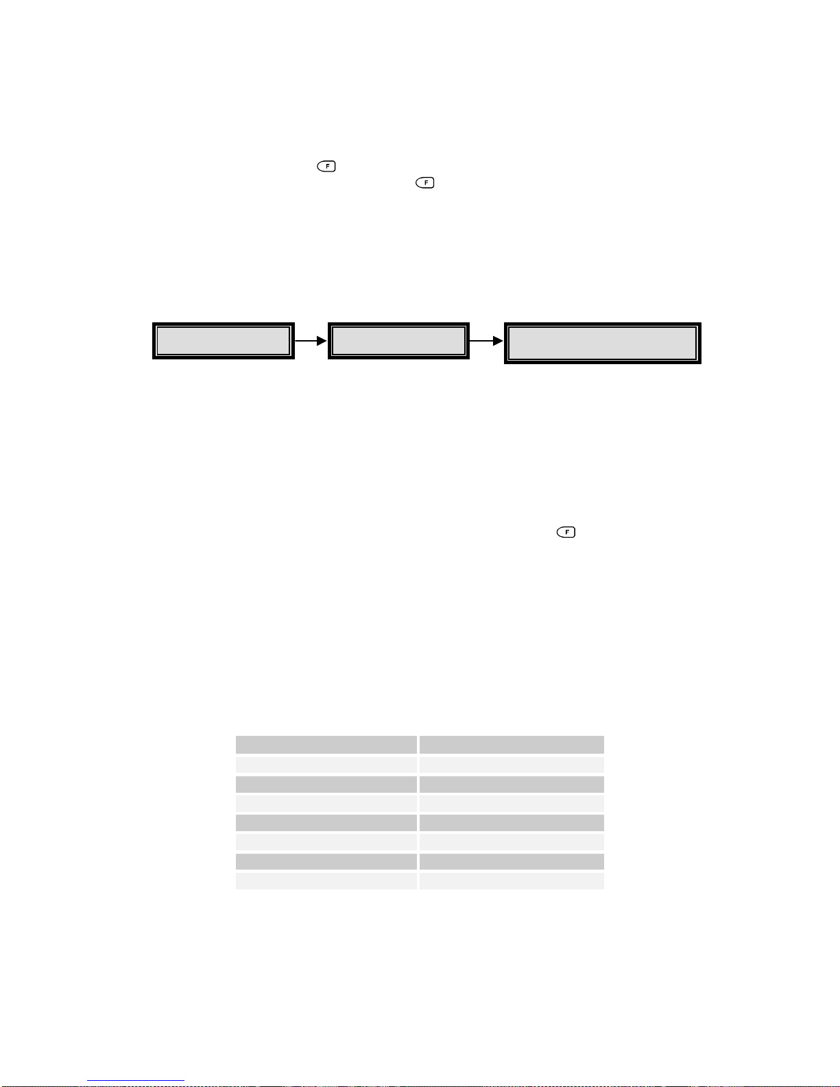
HBZMXSIB/10/16SD-PR-1 Page 61
Up to eight macros, each having 32 key-strokes, can be programmed into the
multiplexer.
Recording is started via the menu system. Playback is started from the front panel
using the FUNCTION key
and camera keys. A macro can be stopped during its
playback by pressing the FUNCTION key
.
The macro functions can be started automatically at up to 20 preset times during the
week by using the built-in macro scheduler, see page 63.
Recording A Macro
Macro recording is started from the menu system, and so macro recording can only
be done if you have the password to the menu system.
To initiate recording, select MACRO in the main menu, and select Macro Record
from the sub-menu. This displays the Macro Record window where you select the
number of the macro that you wish to record (1 to 8). Upon selection, the system will
automatically exit the menus. Subsequent keystrokes will be recorded into that
macro.
Each keystroke will be recorded, until either the FUNCTION key
and ENTER is
pressed to terminate the macro recording, or until 32 keystrokes have been recorded.
Note
An on-screen indicator, Fn plus the macro number, will appear and will stay on the
screen until recording of that macro is complete.
Special Keys Used During Macro Recording
The following two-key combinations provide you with special actions within macros.
Key combination Action
FUNCTION then 1 Activate output relay 1
FUNCTION then 2 Reset output relay 1
FUNCTION then 3 PAUSE macro, 1 second
FUNCTION then 4 PAUSE macro, 5 seconds
FUNCTION then 5 Activate output relay 2
FUNCTION then 6 Reset output relay 2
FUNCTION then ENTER End Macro recording
Main Macro
Macro Record
Page 63

HBZMXSIB/10/16SD-PR-1 Page 62
Menu Setup Using Macros
If you press the MENU key during macro recording, the recording of subsequent
keystrokes is stopped.
Notes
1) Instead of recording keystrokes, the macro only records the final setting of each
set up parameter for those sub-menus which are accessed by you.
2) Upon playback of the macro, the unit will retrieve only those recorded menu set
up parameters, and will set the unit up accordingly.
3) Parameters in sub-menus, which were not accessed during recording of the
macros, will not be recorded or retrieved during playback of the macro.
Exception
In the Motion Detection sub-menu, macros can only be used to enable and disable
motion detection. The other motion detection parameters cannot be set via macros.
The following parameters should, therefore, be set up during installation:
1) Output Relay selection, 1 or 2 or both, per input.
2) Output Relay NO or NC selection.
3) ‘M’ indicator ON/OFF selection
4) Videoloss relays and buzzer selections, per input
5) VCR switch pulse edge selection
6) VCR type A or B selection
7) Setup Parameters
Ending The Recording Of A Macro
Press the FUNCTION key and then the ENTER key to end the recording of a
Macro.
Recommendation
Make a list of the function of each macro with its macro number, for later use in
playing the macros.
A section is provided in the back of this manual to conveniently keep a list of the
macros and their intended functions.
Page 64
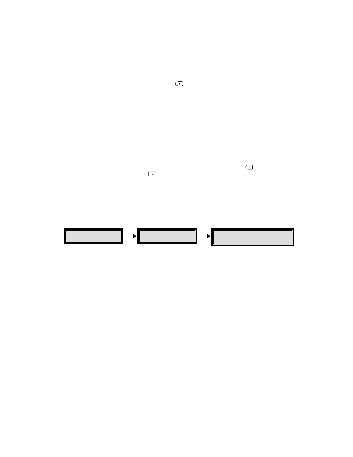
HBZMXSIB/10/16SD-PR-1 Page 63
Note
Each macro can contain 32 keystrokes. Exceeding this will cause the macro
recording to terminate.
There is no macro editing capability. To check a macro function, play back the
Macro by pressing the FUNCTION key
and the macro number (camera key),
and check for correct its operation. If the macro does not appear to function
correctly, delete the macro as described below and re-enter it.
Deleting A Macro
To delete a macro, record an empty macro over it. To record an empty macro, start
macro recording and immediately press FUNCTION plus ENTER to end the
recording.
Playing A Macro
A macro can be played back simply by pressing the FUNCTION key , followed by
the macro number (camera key
).
While the macro is playing back, Fn and the macro number are displayed.
A macro can be stopped during its playback by pressing the FUNCTION key.
Timed Macros
Macros can be started at a fixed time and day of the week by using the Macro
Scheduler. The Macro Scheduler allows you to program up to 20 events which will
automatically run one of the macro functions.
Scheduled events can be started on a preset time on a particular day of the week, or
at a preset time on every day of the week. Any macro can be started by each of the
20 scheduled events, and a macro can be started by more than one event.
To set up the Macro Scheduler, select the Timed Macro Start section of the Macro
sub-menu.
Main Macro
Timed Macro Start
Page 65

HBZMXSIB/10/16SD-PR-1 Page 64
For each of the 20 events choose a Day, a Time and the Macro to run for that event
entry:
Day: select the day of the week, 1-7, on which the event must start a macro. To
see the day of the week corresponding to today’s date, select the Date set up
menu from the Time/Date sub-menu. If the macro is to be run every day at the
same time, select ‘**’ for the Day field. If a 0 is entered for the day, the scheduled
event entry is cancelled and will not start the macro.
Time: Select the time to run the macro function.
Macro: Enter the number of the macro to run.
Keep a record of scheduled events for easy reference. A table is provided in the back
of this manual to list the scheduled events.
Remote Control
RS-232 Remote Control
RS-232 remote control is via a 9 way ‘D’ type connector, on the rear panel. This is
used to provide fully-programmable remote control from a PC or similar controller. It
is possible to read and set up all the menu functions and also control the front panel
controls via the RS-232 port.
Functions included are:
Menu programmed functions
All front panel keys
Alarm history read
Operating Status read
RS-232 baud rates are selectable from 1200 to 9600. The factory default is 9600.
To set the baud rate, select the RS-232 option of the Communications sub-menu.
Refer to Appendix A, RS-232 REMOTE PROTOCOL for more details.
Page 66
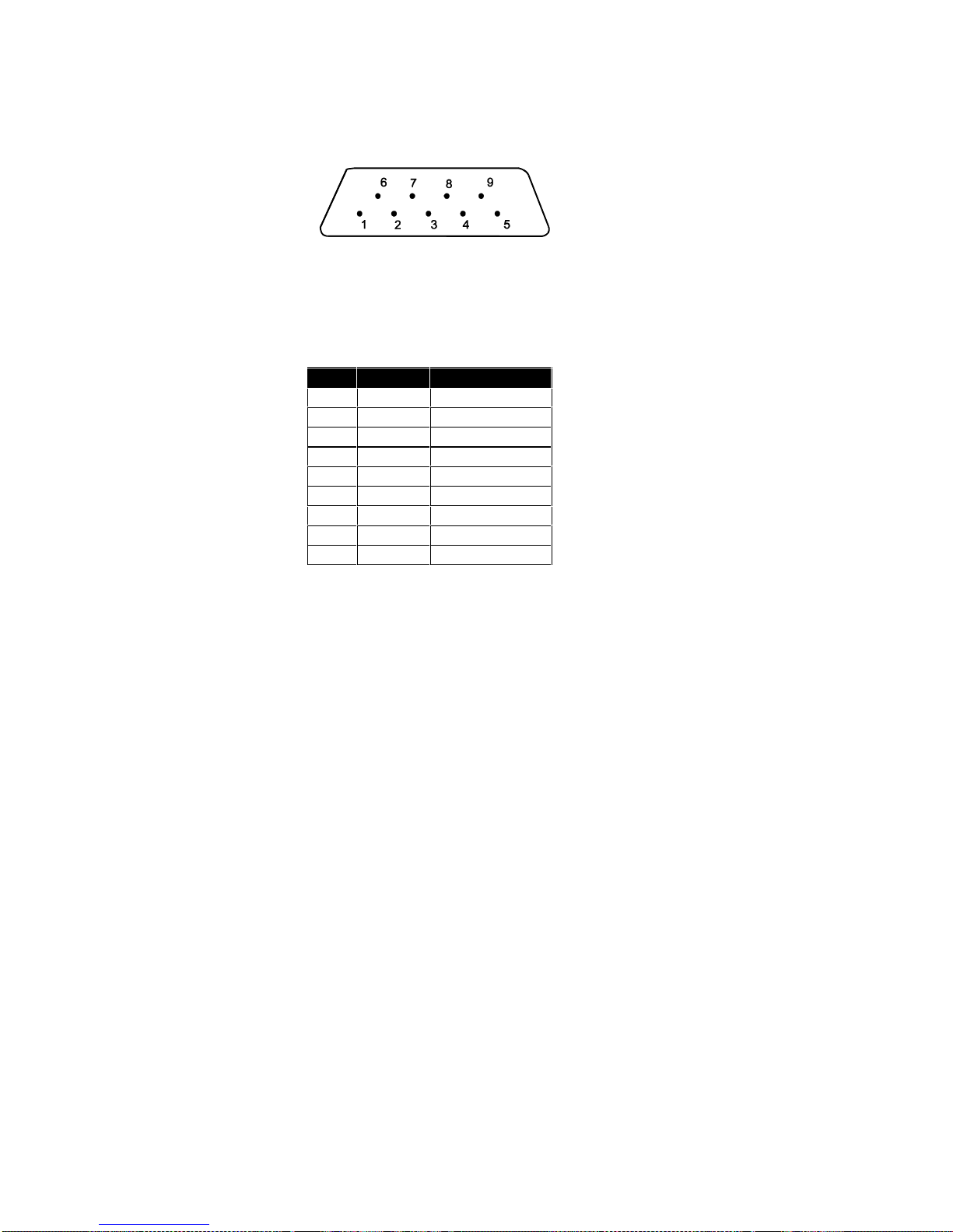
HBZMXSIB/10/16SD-PR-1 Page 65
9-way Connector
Figure 9 9-way Connector Numbering
Pin Signal Function
1 - not used
2 Rx Receive Data
3 Tx Transmit Data
4 - not used
5 GRD Ground
6 - not used
7 - not used
8 - not used
9 - not used
Table 2 9-way Connections
Page 67

HBZMXSIB/10/16SD-PR-1 Page 66
4 Specification
Feature Specification
Password protected system settings
Parallel Video Processing (colour models) ensures a camera update rate typically 2
to 3 times faster than normal multiplexers (without a need to synchronise the
cameras).
Playback of any Baxall ZMX recording, DM compatible recordings (NPX1, NPX+,
DIAMOND, DIAMOND+ and all GEM) and standard video recordings
On-screen programming via menus (settings retained when powered off)
Secure 1 hour adjustment for Summer/Winter time without access to the menu
system.
Inputs and Outputs
10 or 16 loop-through camera inputs, depending on the model, with automatic
termination
Composite and S-VHS VCR input and output (colour models only)
VCR (Vext input) automatically synchronises the recording speed
Dual monitors with on-screen captions
Function Keys
Eight user-defined, macro style functions
Upto 20 event (Macro) Scheduler Macro Function commands, daily, or once a week
at a specified time.
Page 68

HBZMXSIB/10/16SD-PR-1 Page 67
Display Options
LIVE, PLAY and RECORD modes:
Full screen, Sequence (adjustable dwell and camera list), multiscreen, x2 Electronic-
Zoom, Freeze Frame
Full screen, Sequence (adjustable dwell and camera list)
Record and Playback
In 3-hour, multiplexed, record-mode the multiplexer typically records up to 50 unique
fields of video per second, with no requirement for synchronising cameras.
Compatible with all common time-lapse VCRs
Programmable time-lapse modes (Normal and Alarm)
Data restored at playback; time/date, alarms and camera titles
Alarms Events
10 or 16 alarm-inputs each N/O or N/C on a 25-way D-type connector (max 100 ohm
contact resistance)
Videoloss Detection
Activity Detection
Alarm Responses
Interleaving or exclusive recording of alarmed cameras
Normal and Alarmed recording speeds
Alarms : buzzer, flashing LED and on-screen A or ALM text
Videoloss : buzzer, flashing LED and on-screen V or VDL text
Recorded alarms are also indicated during playback
2 Alarm-output relays max 30V AC/DC, contact max 500 mA - N/O or N/C
programmable
Manual-Reset, Auto-Reset, or Contact-Closure
Keyboard and External Alarm Clear
All Video Inputs and Outputs
75 Ohm BNC connectors
Video: 1V pk-pk composite (PAL compatible)
Composite or S-VHS VCR connections
High display resolution 720 x 576, Recorded resolution 720 x 288
Page 69

HBZMXSIB/10/16SD-PR-1 Page 68
Camera Switch Input (Vext)
Accepts a TTL, field-synchronised, negative going pulse, duration 2-5 ms. Edge
triggered with the edge selectable in the menus.
HIGH level, +4.5V to +5.5V
LOW level, 0V
Power
Auto-ranging : 110/230V AC ±10%, 50Hz, to 12V DC external power supply
provided.
Power Consumption: Max : 20W
Physical Specifications
Operational temperature limits:
0 deg C to +40 deg C at 10% to 80% relative humidity (non-condensing)
Storage temperature limits:
-20 deg C to +60 deg C at 10% to 95% relative humidity (non-condensing)
Dimensions (mm) Weight (Kg) Material Colour
358(D)x43(H)x443(W) 4.5 Mild Steel Grey
Page 70
HBZMXSIB/10/16SD-PR-1 Page 69
5 Function List
MACRO # DESCRIPTION
1
2
3
4
5
6
7
8
{F} + Play
VCR VIEW. Selects the VCR as an input so that the VCR can be
set up.
{F} + SEQ
SUMMER / WINTER TIME. Sets clock ahead 1 hour in
March/April and back 1 hour in September / October
Page 71
HBZMXSIB/10/16SD-PR-1 Page 70
6 List Of Scheduled Functions
Day of week set up: Monday = ______
EVENT DAY TIME MACRO TO RUN
1
2
3
4
5
6
7
8
9
10
11
12
13
14
15
16
17
18
19
20
Page 72

HBZMXSIB/10/16SD-PR-1 Page 71
Appendix A
RS-232 Remote Protocol
COMMUNICATION TYPES:-
a. Remote Front Panel Simulation
b. Remote Data and Commands
a. Remote Front Panel Simulation
i) Data structure
Byte 1: 0xFF
Byte 2: 0x55
Byte 3: Front Panel Key Code
ii) Description
Byte 1 & 2 are communication type ID bytes.
Byte 3 contains the code for a specific front panel
key.
The different keys and their corresponding codes
are as
follows.
NO_KEY 0
RECORD_KEY 1
PLAY_KEY 2
LIVE_KEY 3
ALARM_KEY 4
FREEZE_KEY 5
ZOOM_KEY 6
SEQ_KEY 7
MON-A_KEY 8
CAM_1_KEY 9
CAM_2_KEY 10
CAM_3_KEY 11
CAM_4_KEY 12
CAM_5_KEY 13
CAM_6_KEY 14
CAM_7_KEY 15
CAM_8_KEY 16
CAM_9_KEY 17
CAM_10_KEY 18
CAM_11_KEY 19
CAM_12_KEY 20
CAM_13_KEY 21
CAM_14_KEY 22
CAM_15_KEY 23
CAM_16_KEY 24
MENU_SETUP_KEY 25
SELECT_KEY 26
RESERVED 27
MACRO_KEY 28
RESERVED 29
RESERVED 30
RESERVED 31
RESERVED 32
RESERVED 33
MON_B_KEY 34
CAMERA_POWER_KEY 35
WASH_KEY 36
AUTO_PAN_KEY 37
LIGHTS_KEY 38
WIPE_KEY 39
PRESET_KEY 40
FOCUS_FAR_KEY 41
FOCUS_NEAR_KEY 42
IRIS_CLOSE_KEY 43
IRIS_OPEN_KEY 44
ZOOM_IN_KEY 45
ZOOM_OUT_KEY 46
TELEMETRY_KEY 47
LEFT_ARROW_KEY 48
RIGHT_ARROW_KEY 49
UP_ARROW_KEY 50
DOWN_ARROW_KEY 51
UP_LEFT_KEY 52 /* PSUEDO KEY */
DOWN_LEFT_KEY 53 /* PSUEDO KEY */
UP_RIGHT_KEY 54 /* PSUEDO KEY */
DOWN_RIGHT_KEY 55 /* PSUEDO KEY */
RESERVED 56
RESERVED 57
b. Remote Data and Commands
i) Data structure
Byte 1: 0xFF
Byte 2: Command Type
Byte 3: Data Length n
Byte 4: Data Type
Byte 5: Data byte 1
Byte 6: Data byte 2
.
Byte x: Data byte n
ii)Description
Byte 1: Always 0xFF.
Byte 2: Command Type
0xAA: (SET) Update system with data.
0xBB: (GET) Extract data from system.
0xCC: (DO) Reserved.
Byte 3: Contains number of data bytes in the
stream [n]. Range: 0 - 255
Byte 4: Indicates the data type.
The data bytes start at Byte 5.
The data types (Byte 4) are as follows:
For Command Types SET and GET:
0 - TITLE1
1 - TITLE2
2 - TITLE3
3 - TITLE4
4 - TITLE5
5 - TITLE6
6 - TITLE7
7 - TITLE8
8 - TIMEDATE
Page 73

HBZMXSIB/10/16SD-PR-1 Page 72
9 - HISTORY
10 - FSSEQLIST
11 - SPARE
12 - RECLIST
13 - ENCAMERA
14 - ENALARM
15 - DWELLMULTISCREEN
16 - DWELLFULLSCREEN
17 - ALARMTIMEOUT
18 - ALARMINP
19 - MACROLINK
20 - BAUDRATE
21 - DISPLAYTD
22 - DISPLAYTITLE
23 - PBFORMAT
24 - ALARMMODE
25 - TDFORMAT
26 - LANGUAGE
27 - EXTSWITCH
28 - NORRECSPEED
29 - ALMRECSPEED
30 - MACRO1
31 - MACRO2
32 - MACRO3
33 - MACRO4
34 - MACRO5
35 - MACRO6
36 - MACRO7
37 - MACRO8
38 - MACRO9
39 - MACRO10
40 - MACRO11
41 - MACRO12
42 - MACRO13
43 - MACRO14
44 - MACRO15
45 - MACRO16
46 - TITLE9
47 - TITLE10
48 - TITLE11
49 - TITLE12
50 - TITLE13
51 - TITLE14
52 - TITLE15
53 - TITLE16
54 - RESERVED
55 - RESERVED
56 - RESERVED
57 - RESERVED
58 - ENABLACTIVITY
59 - UP_ACT_SETTINGS
60 - UP_ACT_GRID
61 - UP_ALM_AND_VDL
62 - DN_ACT_SETTINGS
63 - DN_ACT_GRID_1
64 - DN_ACT_GRID_2
65 - DN_ACT_GRID_3
66 - DN_ACT_GRID_4
67 - DN_ACT_GRID_5
68 - DN_ACT_GRID_6
69 - DN_ACT_GRID_7
70 - DN_ACT_GRID_8
71 - DN_ACT_GRID_9
72 - DN_ACT_GRID_10
73 - DN_ACT_GRID_11
74 - DN_ACT_GRID_12
75 - DN_ACT_GRID_13
76 - DN_ACT_GRID_14
77 - DN_ACT_GRID_15
78 - DN_ACT_GRID_16
79 - DN_TIMED_MACRO
80 - REC_LOCK
81 - VCR_TYPE
82 - SWITCH_EDGE
83 - NETWORK_ADDRESS
For command type DO;
0 - Reserved
UPLOADING DATA BYTES
When a message of type 0xBB is sent to the system, it
will respond by sending a 0xff start byte, followed by the
requested information, followed by a 0xff stop byte.
CHANGING AND ACCESSING
INDIVIDUAL PARAMETERS
a) Changing Camera Titles
buffer[0] = 0xff;
buffer[1] = 0xAA;
buffer[2] = 13;
buffer[3] = TITLE1 to TITLE16;
buffer[4] - buffer[16] = The title:-
(12 ASCII characters + NULL
terminator);
b) Changing the time and date
buffer[0] = 0xff;
buffer[1] = 0xAA;
buffer[2] = 12;
buffer[3] = TIMEDATE;
buffer[4] = Month MSB;
buffer[5] = Month LSB;
buffer[6] = Day MSB;
buffer[7] = Day LSB;
buffer[8] = Year MSB;
buffer[9] = Year LSB;
buffer[10] = Hour MSB;
buffer[11] = Hour LSB;
buffer[12] = Minute MSB;
buffer[13] = Minute LSB;
buffer[14] = Second MSB;
buffer[15] = Second LSB;
c) Request alarm history list
buffer[0] = 0xff;
buffer[1] = 0xBB;
buffer[2] = 0;
buffer[3] = HISTORY;
d) Changing the Full Screen Sequence list
buffer[0] = 0xff;
buffer[1] = 0xAA;
buffer[2] = 30;
buffer[3] = FSSEQLIST;
buffer[4] - buffer[33] = BINARY list of 30 numbers .
Allowable numbers (1 - 16)
e) SPARE
f) Changing the record list
buffer[0] = 0xff;
buffer[1] = 0xAA;
buffer[2] = 30;
buffer[3] = RECLIST;
buffer[4] - buffer[33] = BINARY list of 30 numbers .
Allowable numbers (1 - 16)
g) Enabling or disabling certain cameras
buffer[0] = 0xff;
buffer[1] = 0xAA;
Page 74

HBZMXSIB/10/16SD-PR-1 Page 73
buffer[2] = 16;
buffer[3] = ENCAMERA;
buffer[4] - buffer[19] = BINARY list of 16 numbers -
digits (0 - Disable,1 -Enable)
h) Enabling or disabling certain alarms
buffer[0] = 0xff;
buffer[1] = 0xAA;
buffer[2] = 16;
buffer[3] = ENALARM;
buffer[4] - buffer[19] = BINARY list of 16 numbers -
digits (0 - Disable,1 -Enable)
i) Changing the Multiscreen Dwell time
buffer[0] = 0xff;
buffer[1] = 0xAA;
buffer[2] = 1;
buffer[3] = DWELLQUAD;
buffer[4] = BINARY dwell time in seconds (1-99);
j) Changing the Full Screen Dwell time
buffer[0] = 0xff;
buffer[1] = 0xAA;
buffer[2] = 1;
buffer[3] = DWELLFS;
buffer[4] = BINARY dwell time in seconds (1-99);
k) Changing the Alarm ON time
buffer[0] = 0xff;
buffer[1] = 0xAA;
buffer[2] = 1;
buffer[3] = ALARMTO;
buffer[4] = BINARY alarm time in seconds (1-99);
l) Alarm input configuration
buffer[0] = 0xff;
buffer[1] = 0xAA;
buffer[2] = 16;
buffer[3] = ALARMINP;
buffer[4] - buffer[19] = BINARY list of 16 numbers -
digits (0 - Normally Closed,1 - Normally Open)
m) Changing the macro link values
buffer[0] = 0xff;
buffer[1] = 0xAA;
buffer[2] = 16;
buffer[3] = MACROLINK;
buffer[4] - buffer[19] = BINARY list of 16 numbers -
digits (1 - 16)
n) Changing the Baudrate of the Remote channel:
buffer[0] = 0xff;
buffer[1] = 0xAA;
buffer[2] = 1;
buffer[3] = BAUDRATE;
buffer[4] = BINARY number
(0 - 1200 1 - 2400 2 - 4800 3 - 9600)
o) Enable or disable the display of the time and the
date
buffer[0] = 0xff;
buffer[1] = 0xAA;
buffer[2] = 1;
buffer[3] = DISPLAYTD;
buffer[4] = BINARY number (0 - disable,1 - enable);
p) Enable or disable the display of the titles
buffer[0] = 0xff;
buffer[1] = 0xAA;
buffer[2] = 1;
buffer[3] = DISPLAYTITLE;
buffer[4] = BINARY number (0 - disable,1 - enable);
q) Changing the Playback format
buffer[0] = 0xff;
buffer[1] = 0xAA;
buffer[2] = 1;
buffer[3] = PBFORMAT;
buffer[4] = BINARY number
(0 - ZMX decode,1 - System 8000,2 - DM
Compatible);
r) Changing the alarm mode
buffer[0] = 0xff;
buffer[1] = 0xAA;
buffer[2] = 1;
buffer[3] = ALARMMODE;
buffer[4] = BINARY number
(0 - Latched,1 - Transparent,2 - Timed Out);
s) Changing the time and date format
buffer[0] = 0xff;
buffer[1] = 0xAA;
buffer[2] = 2;
buffer[3] = TDFORMAT;
buffer[4] = BINARY number - Time format
(0 - 12hour,1 - 24hour);
buffer[5] = BINARY number - Date format
(0 - mm/dd/yy,1 - dd/mm/yy,2 -yy/mm/dd);
t) Changing the menu language
buffer[0] = 0xff;
buffer[1] = 0xAA;
buffer[2] = 2;
buffer[3] = LANGUAGE;
buffer[4] = BINARY number - Language
(0 - Eng, 1 - 4 = per Eproms supplied);
u) Enabling or disabling the external VCR switch
buffer[0] = 0xff;
buffer[1] = 0xAA;
buffer[2] = 1;
buffer[3] = EXTSWITCH;
buffer[4] = BINARY number - (0 - Disable,1 - Enable);
v) Setting the normal record speed
buffer[0] = 0xff;
buffer[1] = 0xAA;
buffer[2] = 1;
buffer[3] = NORRECSPEED;
buffer[4] = BINARY number - (1 - 13);
w) Setting the alarm record speed
buffer[0] = 0xff;
buffer[1] = 0xAA;
buffer[2] = 1;
buffer[3] = ALMRECSPEED;
buffer[4] = BINARY number - (1 - 13);
x) Creating a macro sequence
buffer[0] = 0xff;
Page 75

HBZMXSIB/10/16SD-PR-1 Page 74
buffer[1] = 0xAA;
buffer[2] = number of bytes starting from buffer[4];
buffer[3] = MACRO1 to MACRO16;
buffer[4] - buffer[x] The macro sequence keys
The numerical values of the keys are as follows:
Record = 1
Play = 2
Live = 3
Alarm = 4
Freeze = 5
Zoom = 6
Sequence = 7
Multiscreen = 8
’1’ = 9
’2’ = 10
’3’ = 11
’4’ = 12
’5’ = 13
’6’ = 14
’7’ = 15
’8’ = 16
’9’ = 17
’10’ = 18
’11’ = 19
’12’ = 20
’13’ = 21
’14’ = 22
’15’ = 23
’16’ = 24
Setup = 25
Select = 26
RESERVED = 27
RESERVED = 28
Macro Special 1 = 29 /* Activate Alarm Output 1*/
Macro Special 2 = 30 /* Reset Alarm Output 1 */
Macro Special 3 = 31 /* Pause Macro for 1 sec ond
*/
Macro Special 4 = 32 /* Pause Macro for 5 seconds
*/
RESERVED = 33
Mon_B Key = 34
Camera Power Key = 35
Wash Key = 36
Auto Pan Key = 37
Lights Key = 38
Wipe Key = 39
Preset Key = 40
Focus Far Key = 41
Focus Near Key = 42
Iris Close Key = 43
Iris Open Key = 44
Zoom In Key = 45
Zoom Out Key = 46
Telemetry_Key = 47
Left Arrow Key = 48
Right Arrow Key = 49
Up Arrow Key = 50
Down Arrow Key = 51
Up Left Key = 52
Down Left Key = 53
Up Right Key = 54
Down Right Key = 55
Macro Special 5 = 56 /* Activate Alarm Output 2 */
Macro Special 6 = 57 /* Reset Alarm Output 2 */
The last byte of the macro buffer[x] = 58; Macro_End
The number of bytes in the macro may not exceed 32.
y) Enable activity detection
buffer[0] = 0xff;
buffer[1] = 0xAA;
buffer[2] = 16;
buffer[3] = ENACTIVITY;
buffer[4] - buffer[19] = BINARY list of 16 numbers -
digits (0 - disable, 1 -enable)
z) Request activity settings
buffer[0] = 0xff;
buffer[1] = 0xBB;
buffer[2] = 0;
buffer[3] = UP_ACT_SETTINGS;
aa) Request activity grid
buffer[0] = 0xff;
buffer[1] = 0xBB;
buffer[2] = 0;
buffer[3] = UP_ACT_GRID;
ab) Request alarm and videoloss status
buffer[0] = 0xff;
buffer[1] = 0xBB;
buffer[2] = 0;
buffer[3] = UP_ALM_AND_VDL;
ac) Download activity grid
buffer[0] = 0xff;
buffer[1] = 0xAA;
buffer[2] = 32;
buffer[3] = DN_ACT_GRID_1 to DN_ACT_GRID_16;
buffer[4] - buffer[35] BINARY digits correspondi ng to
zones.
Two bytes per row, 16 rows. (1 - active, 0 off)
NOTE: This message must be used with caution.
Delays of 100ms must be inserted between
consecutive camera grids.
ad) Downloading Timed Macro Information
buffer[0] = 0xff;
buffer[1] = 0xAA;
buffer[2] = 6;
buffer[3] = DN_TIMED_MACRO;
buffer[4] = Event number (1 - 20)
buffer[5] = Day (0 - 8) 0 -> Disabled
buffer[6] = Hour (1 - 12)
buffer[7] = Minute (0 - 59)
buffer[8] = AM/PM (0 - AM, 1 - PM)
buffer[9] = Macro Number (1-16)
ae) Setting the Record Lock
buffer[0] = 0xff;
buffer[1] = 0xAA;
buffer[2] = 1;
buffer[3] = REC_LOCK;
buffer[4] = 0 - OFF, 1 - ON
af) Setting the VCR Type
buffer[0] = 0xff;
buffer[1] = 0xAA;
buffer[2] = 1;
buffer[3] = VCR_TYPE;
buffer[4] = 0 - Type A,1 - Type B
ag) Setting the Vext Pulse active edge
buffer[0] = 0xff;
buffer[1] = 0xAA;
buffer[2] = 1;
buffer[3] = SWITCH_EDGE;
Page 76

HBZMXSIB/10/16SD-PR-1 Page 75
buffer[4] = 1 - Negative Edge,0 - Positive Edge
ah) Setting the Network Address
buffer[0] = 0xff;
buffer[1] = 0xAA;
buffer[2] = 1;
buffer[3] = NETWORK_ADDRESS;
buffer[4] = Binary number (0-255)
UPLOADING DATA
a) Alarm history list
When the "Request Alarm History List" message is
received by the system, it will respond by sending an
ASCII string for every alarm event in its alarm history
list. The string is formatted as follows:
dd.bmm/ddbhh:mm:ss<CR><LF>
dd - alarm event number (0 - 99)
b - space character
mm - month
dd - day
hh - hours
mm - minutes
ss - seconds
<CR><LF> - Carriage return /line-feed pair
b) Activity settings
Six bytes are uploaded:
i) Sensitivity, (1 - 10 )
ii) Relay, (0 - none, 1 - relay 1, 2 - relay 2, 3 - both)
iii) Link to Alarm, (1 - 16)
iv) False Alarm Rejection, (0 - low, 1 - medium, 2 - high)
v) Size Discrimination, (1 - 255)
vi) Record Rate, (0 - none, 1 - 2x, 2 - 4x, 3 interleaved)
c) Activity grids
16 x 32 bytes are uploaded. 1st 32 bytes are zones
from camera 1, 2nd 32 bytes from camera 2, etc.
(Two bytes per row, 16 rows)
d) Alarm and videoloss
4 bytes are uploaded. The 1st 2 represent the alarms in
the system (MSB,LSB).
The next 2 bytes represent the videoloss status (MSB,
LSB).
Page 77

HBZMXSIB/10/16SD-PR-1 Page 76
Appendix B
Flicker Adjustment
The mono multiplexer units do not require flicker adjustment.
For colour multiplexer units, do the following.
Before recording any cameras, the two decoder channels need to be calibrated to
reduce flicker on playback.
Note
You must use camera 1 for this set-up.
1) Display camera 1 full screen on Monitor-A.
Camera-1 must be in full resolution mode (frame display) and not it half resolution
mode (field display). The half resolution mode is indicated on the monitor by the
presence of the - character to the left of the time and date display. Press the
camera 1 key to toggle this feature on and off.
2) Normally the picture will flicker. Reduce the flicker by pressing the up or down
arrow keys
.
Note
These are not repeating keys. Do not hold them down. They must be released
each time you press them.
These settings are stored in the battery backed up memory, however, every time a
unit is reset using the RUN/CLR jumper, or by commanding a Factory Settings
reset, this procedure must be repeated.
Page 78

HBZMXSIB/10/16SD-OP-1 Page 2
This page is intentionally blank.
Page 79

HBZMXSIB/10/16SD-OP-1 Page 3
This Manual
This manual provides operating instructions for the ZMX/BD/10, ZMX/BS/10MD and
ZMX/CS/10 Multiplexers. It does not include programming instructions, which are
provided in the Programming Instructions Manual
Section 1 provides important safety information.
Section 2 provides the operating instructions.
Page 80

HBZMXSIB/10/16SD-OP-1 Page 4
This page is intentionally blank.
Page 81

HBZMXSIB/10/16SD-OP-1 Page 5
Contents
1 IMPORTANT SAFEGUARDS 7
1.1 Safety 9
2 OPERATING INSTRUCTIONS 10
2.1 The Basics 11
Multiplexing 12
Explan ati o n of M ul ti pl exing 12
Time Lapse VCRs 13
Features of your Multiplexer 13
2.2 Modes of Operation 14
Differences Between the Operation of Simplex and Duplex Models 14
Record Mode 14
Play Mode 15
Live Mode 15
Output To The VCR Duri ng Li ve M od e A nd Pl ay Mode 15
Videoloss 15
The Menu S y st em 16
2.3 The Keys 16
ALARM key 16
FREEZE key 17
ZOOM key 17
Multi-screen key 17
LIVE mode key 17
RECORD mode key 17
PLAY mode key 18
Adjusting the Picture Brightness and Contrast During Playback 19
FUNCTION key 19
SEQUENCE key 19
CAMERA keys 19
ARROW key 20
MENU key 20
ENTER key 20
MON-B Key 20
One Hour Adjustment For Summer/Winter Time Changes 20
2.4 Multi-screen Formats 21
2.5 Monitor Outputs 22
Monitor-B 22
Monitor-A 22
Selecting Active Cameo Mode 24
PIP Display - Size And Position 25
Changing Positions And Colours Of Titles 25
2.6 Setting The VCR Playback Speed 27
PLAY Mode - Monitor-A Indications 27
Play Mode - Changing Text Positions And Colours 28
Page 82

HBZMXSIB/10/16SD-OP-1 Page 6
2.7 Alarms 29
Alarm Handling Capability 29
Alarm Displays In Live Mode 29
Alarm Displays In Play Mode 30
Alarm Displays In Record Mode, Simplex Models Only 30
Alarm Indicators 31
Alarm Latching 31
Videoloss 31
Selecting VCR As An Input (VCR View) 32
Summer / Winter Time Change 32
Adjusting The VCR Brightness And Contrast 32
2.8 Macro Functions 33
Playing A Macr o 33
3 FUNCTION LIST 34
4 LI S T OF SCHEDULED FUNCTIONS 35
Page 83

HBZMXSIB/10/16SD-OP-1 Page 7
1 Important Safeguards
This product is exclusively for use in CCTV applications and has no other purpose.
Read and Retain the Instructions - All the safety and operating instructions should
be read before the unit is operated and should be retained for future reference.
Cleaning - Unplug the unit from the outlet before cleaning. Do not use liquid cleaners
or aerosol cleaners. Use a damp cloth for cleaning.
Attachments - Do not use attachments not recommended by the product
manufacturer as they may cause hazards.
Water and Moisture - Do not use this unit near water. For example, near a bathtub,
wash bowl, kitchen sink, or laundry tub, in a wet basement, near a swimming pool, in
an unprotected outdoor installation, or any area that is classified as a wet location.
Accessories - Do not place this unit on an unstable stand, tripod, bracket, or mount.
The unit may fall, causing serious injury to a person and serious damage to the unit.
Any mounting of the unit should follow the manufacturer’s instructions, and should
use a mounting accessory recommended by the manufacturer.
Ventilation - Openings in the enclosure, if any, are provided for ventilation to ensure
reliable operation of the unit and to protect it from overheating, these openings must
not be blocked or covered. This unit should not be placed in a built-in installation
unless proper ventilation is provided. Do not place directly on other hot equipment,
because this may increase its operating temperature.
Power Sources - This unit should be operated only from the class 2 isolated power
supply provided.
Plugs - This unit may be equipped with a 3-wire grounding-type plug, a plug having a
third (grounding) pin. This plug will only fit into a grounding-type power outlet. This is
a safety feature. If you are unable to insert the plug into the outlet, contact your
electrician to replace your obsolete outlet. Do not defeat the safety purpose of the
plug.
Power-cord Protection - Power-supply cords should be routed so that they are not
likely to be walked on or pinched by items placed upon or against them, paying
particular attention to cords at plugs, and the point where they exit from the
appliance.
Overloading - Do not overload outlets and extension cords as this can result in a risk
of fire or electric shock.
Object and Liquid Entry – This equipment must be protected from the ingress of
foreign materials. Never push objects of any kind into this unit through openings as
they may touch dangerous voltage points or short-out parts that could result in a fire
or electric shock. Never spill liquid of any kind on the unit.
Page 84

HBZMXSIB/10/16SD-OP-1 Page 8
Servicing – There are no user-serviceable parts. Do not remove the covers as this
may expose you to dangerous voltages or other hazards, including moving
mechanical parts. Refer all servicing to qualified service personnel.
Replacement Parts - When replacement parts are required be sure the service
technician has used the replacement parts specified by the manufacturer.
Unauthorised substitutions may result in fire, electric shock or other hazards.
Safety Check - Upon completion of any service or repairs to this unit, ask the service
technician to perform safety checks to determine that the unit is in proper operating
condition.
Coax Grounding - If an outside cable system is connected to the unit, be sure the
cable system is grounded.
Lightning - For added protection of this unit during a lightning storm, or when it is left
unattended and unused for long periods, unplug it from the wall outlet and disconnect
the cable system. This will prevent damage to the unit due to lightning and power-line
surges.
Page 85

HBZMXSIB/10/16SD-OP-1 Page 9
1.1 Safety
If you have any problems then contact Baxall Limited.
WARNING
Installation is only to be carried out by competent, qualified and experienced
personnel in accordance with the country of installation’s National Wiring
Regulations.
WARNING
Your multiplexer contains no user-serviceable parts inside.
WARNING
This unit contains a lithium battery whose expected life is in excess of five years. If
your multiplexer looses its settings each time it is switched off then the battery
needs replacing. In this instance return your multiplexer to Baxall Limited and we
will replace the battery.
WARNING
There is a danger of explosion if the lithium battery is incorrectly replaced.
Replace only with the same or an equivalent type recommended by the
manufacturer. Dispose of unused batteries according to the manufacturers
instructions.
WARNING
Do NOT use the 12V power leads in the RS-485 cable UNLESS it is to be used on
a one-to-one connection between a unit with 12V power and a unit with no 12V
power. For example, from a multiplexer directly to a keyboard that does not have
its own power source.
In all other circumstances, such as multi-dropped multiplexers, do NOT use the
12V power leads in the RS-485 cable, use only the two wires for the actual 485
comms.
Refer to Baxall Limited before using your multiplexer in a medical and/or intrinsically
safe application.
Do not exceed the voltage and temperature limits given in the specification. Only
operate your multiplexer in a clean, dry, dust-free environment.
Note
The multiplexer’s main function is to multiplex video and its secondary function is
to provide alarms. For this reason, Baxall Limited recommend that you do not use
your multiplexer as the main alarm system on your site but install a dedicated
intruder/fire alarm where necessary.
Page 86

HBZMXSIB/10/16SD-OP-1 Page 10
2 Operating Instructions
The products described in this manual are:
• ZMX/BD/10 10-way, Monochrome Duplex Multiplexer
• ZMX/BS/10 10-way, Monochrome Simplex Multiplexer
• ZMX/CS/10, 10-way, Colour Simplex Multiplexer
You can check which particular model you have by looking at the label on the bottom
right of the unit’s front panel.
The models include many advanced features such as activity detection, alarm
handling, zoom, an alarm history log, programmable macro function keys, a
scheduler to automatically start macros at pre-set times, a simple Summer/Winter
time change function, access to Rugby Clock time control, remote programming and
remote control, and they can be set-up quickly using easy-to-use, on-screen menus.
With all of the models, the front panel contains all the operator control keys and
indicators, while the video inputs, video outputs, alarm inputs and outputs, and the
remote control connectors are on the rear panel.
The controls and indicators have been designed to be convenient and easy to use.
All the models have 12 V DC power and are supplied with external AC power
supplies. The colour models can accept either colour or monochrome video inputs
without any additional set-up.
In general, the operating instructions provided in this document apply to all of the
above models unless stated otherwise.
This manual assumes that your multiplexer has been installed already and is working
correctly. It provides you with all the necessary day-to-day operating instructions,
with the exception of the use of the MENU system, which is described in the
Programming Instructions manual. It is assumed that you are new to the concept of
multiplexers.
Page 87
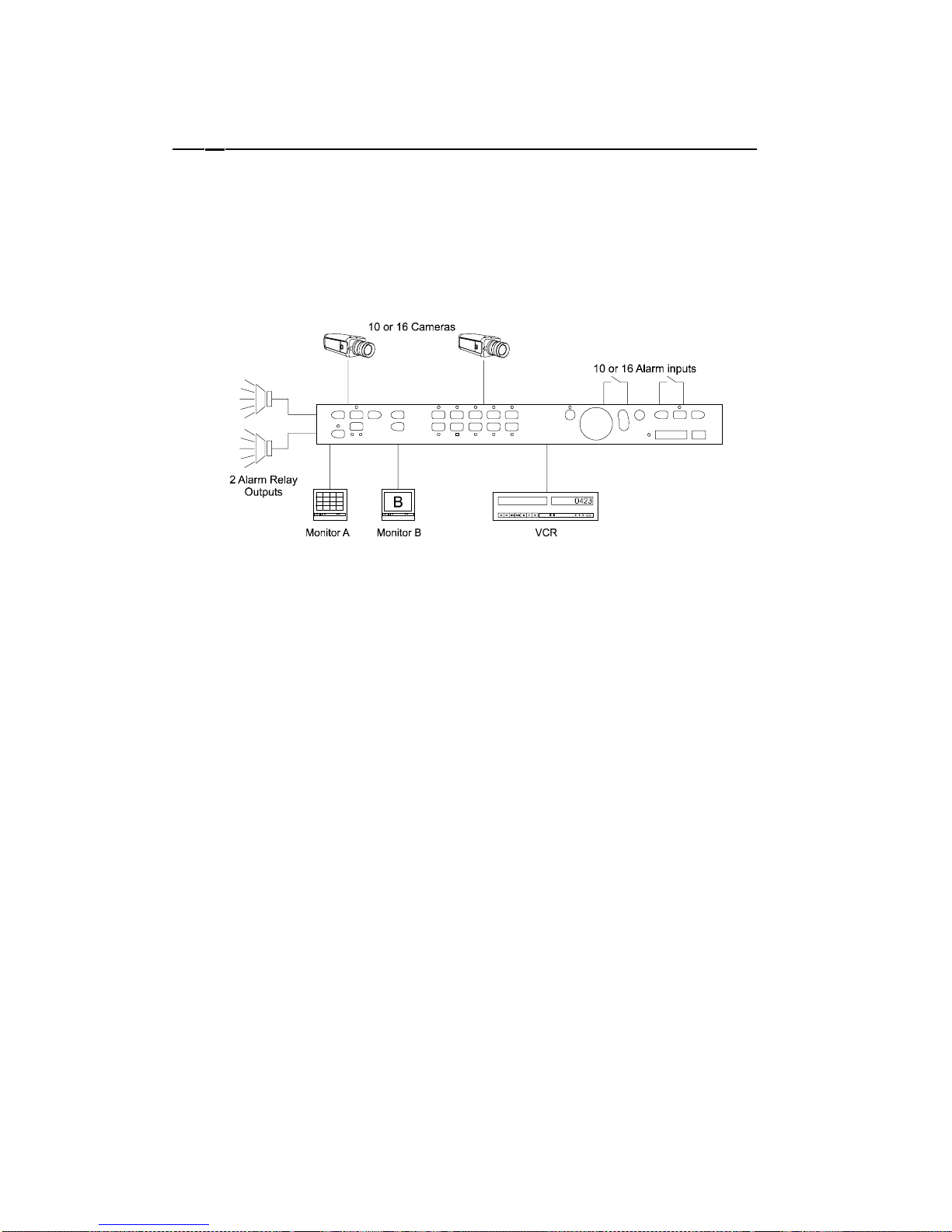
HBZMXSIB/10/16SD-OP-1 Page 11
2.1 The Basics
Your multiplexer, depending on the model, has a maximum of 10 or 16 camera
inputs. It has 10 or 16 alarm inputs (which are normally associated with each
camera), two alarm outputs, two monitor outputs (Monitor-A and monitor-B) and VCR
output and input connections.
A typical installation is shown in Figure 1.
The multiplexer provides you with sophisticated facilities for surveillance monitoring,
and it can record images from all of the connected cameras onto a single video
recorder.
In Figure 1, Monitor-A is used for multi-screen, digital images, which can be frozen
and zoomed. That is, you can choose to view more than one camera at once on the
same screen, you can freeze the images, and you can select a camera and
electronically zoom (x 2) into it. Monitor-B is a full-screen, live, analogue output,
which cannot be frozen or zoomed. Monitor-B is sometimes referred to as a ‘Spot’
monitor in the security industry.
The alarm inputs are normally associated with each of the cameras. When an alarm
has been activated, this can be indicated on the monitor screen. At the same time, an
LED on the unit’s front panel can be made to flash, and a buzzer sounded.
Depending on the way your system has been programmed, you may need to press
the alarm button to acknowledge it, or it might cancel itself either after a fixed period
or when the alarm device is deactivated. When an alarm does occur, Monitor-B
always switches to full screen display of the associated camera, and if there are
multiple alarms, Monitor-B will sequence between the associated cameras. MonitorA, on the other hand, will behave differently, depending which mode the multiplexer
is operating in and which model is being used. For more information on the handling
of alarms, refer to the Programming Instructions manual.
Figure 1 Typical Installation
Page 88
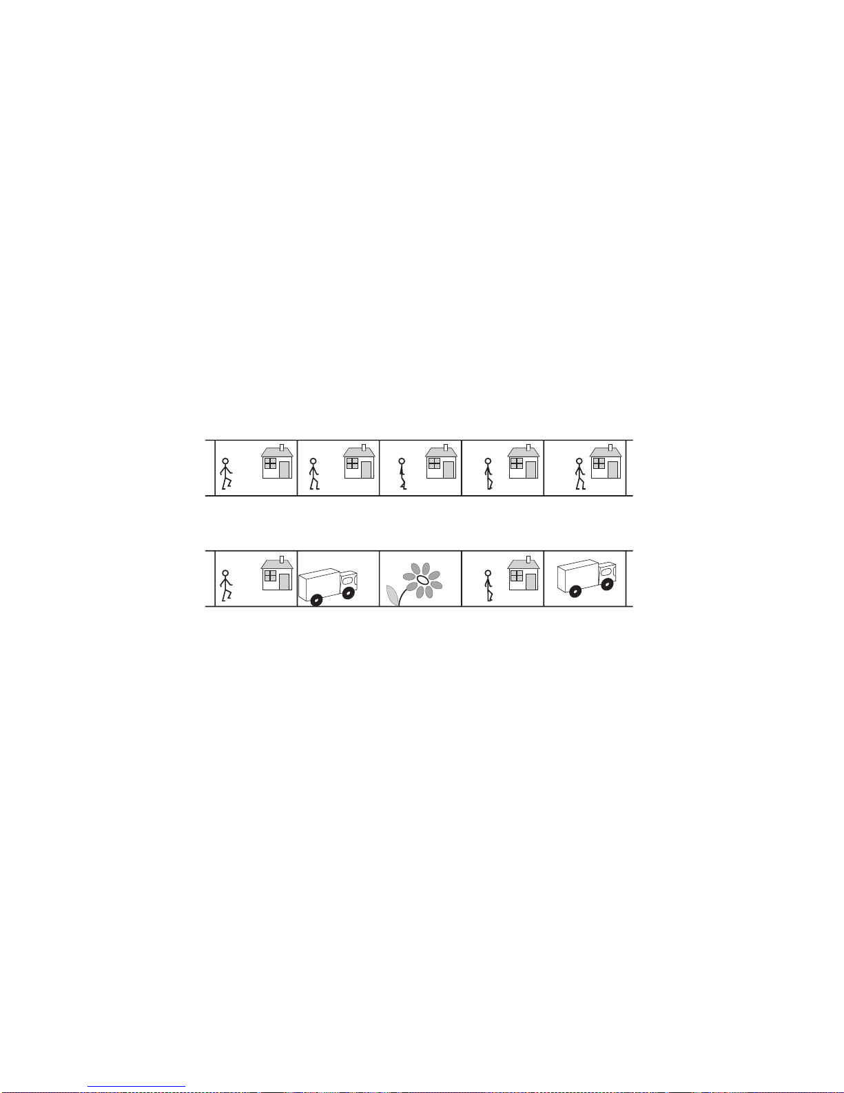
HBZMXSIB/10/16SD-OP-1 Page 12
Multiplexing
The purpose of multiplexing is to reduce the number of VCRs and cassettes required
on a site. A multiplexer gives a VCR output with the ability to record all the connected
cameras to a single VCR.
Explanation of Multiplexing
A PAL compatible TV shows a series of 25 still pictures per second (known as
frames, each made up of two fields) which give the impression of motion. Normally a
VCR would record every frame. Multiplexing (time-division-multiplexing), as done by
your multiplexer, means that the camera signals are combined as a single signal
from all the cameras, 1 picture from each and then back to the first (see Figure 2).
This gives a slightly more jerky image (a Charlie Chaplin effect) on playback and for
example, loses 9 images in 10 for 10 cameras, but means that several cameras can
be recorded on one VCR.
Trikcy BV
Trikcy BV
Camera 2 input
Cameras 1, 2 and 3 multiplexed to tape
2
2
3
2
1
2
2
2
3
2
Figure 2 Illustration of Multiplexing
Page 89
HBZMXSIB/10/16SD-OP-1 Page 13
Time Lapse VCRs
The time-lapse VCR reduces the number of cassettes required for a site. It also
reduces the amount of time spent changing them and the amount of storage space
required for them. Time-lapse VCRs record and play tapes more slowly by recording
fewer images. The speed of operation for a normal VHS VCR is 3 hours. The table
below gives examples of how many fields can be recorded on a 3 hour tape per
camera in various time-lapse modes.
Time Lapse mode fields per second
with 1 camera
fields per second
with 10 cameras
fields per second
with 16 cameras
3 hour 50 5 3.125
12 hour 12.5 1.25 .78
24 hour 6.25 .625 .39
48 hour 3.13 .313 .2
Table 1 Time-lapse modes and recording quality
Features of your Multiplexer
To produce multi-screen displays and to multiplex cameras to tape, the multiplexer
digitises the camera input signals in sequence. For the colour models, unlike other
similar multiplexers, it uses ’Parallel Video Processing’ which means that it does it
more quickly. The camera update rate to tape is typically 2 to 3 times faster than its
competitors. This makes the image less jerky by capturing the maximum of 50 unique
fields-per-second to tape in the fastest time-lapse setting, which means that if an
incident occurs, less information is lost.
Page 90
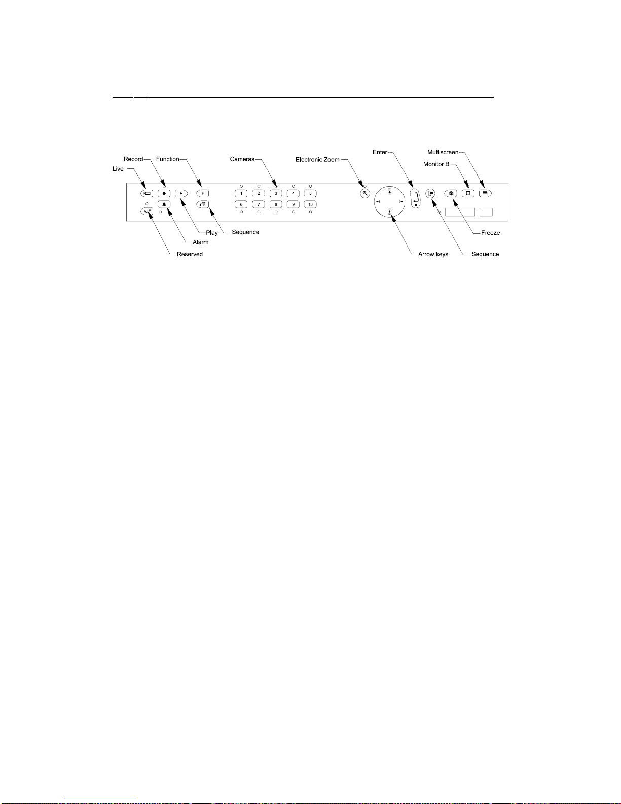
HBZMXSIB/10/16SD-OP-1 Page 14
2.2 Modes of Operation
Your multiplexer has three modes of operation, LIVE, RECORD and PLAY selected
by using the LIVE, RECORD and PLAY keys (see Figure 3).
The operation of these modes depends upon whether your multiplexer is a Simplex
model (ZMX/BS/10 or ZMX/CS/10) or a Duplex model (ZMX/BD/10).
Note
Selecting RECORD mode or PLAY mode does not start the VCR. The VCR must
be started manually.
Differences Between the Operation of Simplex and Duplex Models
Simplex models can be operated in
one
of the three principal modes at any one time.
Duplex models always operate in
two
principal modes simultaneously. The duplex
model has dual digital video processors, and as a result it always has the multiplexed
RECORD mode active in the background. You can, therefore, choose LIVE or PLAY
mode while the unit continues to record.
Record Mode
RECORD mode provides output to the VCR in multiplexed format. Single images
from up to 16 video input channels (depending on the model of multiplexer) are
assembled to form a continuous multiplexed video signal, which can then be
recorded onto a single VCR via the VCR OUT connector.
Note
During the RECORD mode on a simplex model, the MONITOR-A multi-screen
output displays only an analogue, full-screen video of any of the input cameras.
During this time, the Monitor-A output is identical to the Monitor-B output.
RECORD mode can be locked ON in simplex models.
For more information on recording see the Programming Instructions manual.
Figure 3 ZMX/CS/10 Front Panel
Page 91

HBZMXSIB/10/16SD-OP-1 Page 15
Play Mode
PLAY mode plays back a previously-recorded multiplexed tape. Upon entering the
PLAY mode, the multiplexer will automatically select a multi-screen display which
shows you all the possible recorded images on Monitor-A. You can view the
playback in full-screen or multi-screen formats, similar to LIVE mode formats. The
unit automatically reconstructs each camera’s identification, its status, and the date
and time which was current at the time of recording and then displays it with the
corresponding camera image.
In play mode you can also adjust the brightness and contrast of the display.
Your multiplexer can decode Baxall and DM compatible recordings. You can select
which in the menu system. The DEFAULT format decodes recordings from Baxall
ZMX-IT and ZMX-Storm mulitplexers.
Note
It is important to remember that Monitor-B continues to display live, full-screen
images during PLAY mode. Only Monitor-A displays playback images.
Live Mode
There are several different multi-screen display formats that can be selected by you
on the Monitor-A multi-screen output during LIVE mode.
These are described in section Multi-screen Formats
Output To The VCR During Live Mode And Play Mode
During LIVE or PLAY mode, the signal on the unit’s VCR output is different for
simplex and duplex models. For duplex models, there is always a multiplexed video
signal present on the VCR output for multiplexed recording. For simplex models, the
VCR output only has multiplexed output when in record mode.
Videoloss
Your multiplexer monitors the video inputs for video loss. If it detects videoloss, it can
sound the buzzer (if enabled, the default is OFF), flashes the videoloss LED (the
right-hand LED under the ALARM key) and displays VDL text on the full-screen
display and V in a multi-screen.
Note
After a camera is restored from video-loss, you should select it full-screen. This
ensures the fastest recognition by the multiplexer that the camera is now
connected.
Page 92
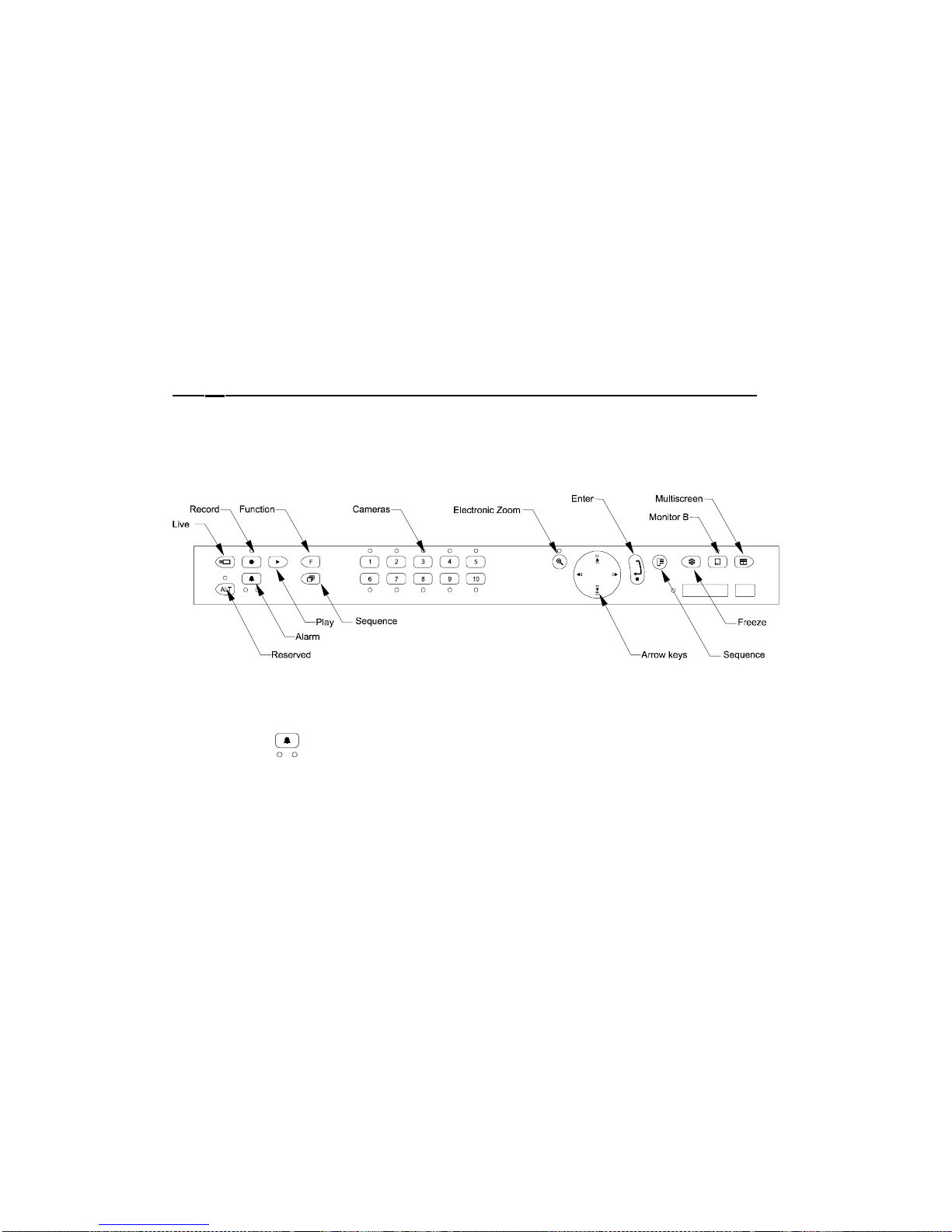
HBZMXSIB/10/16SD-OP-1 Page 16
The Menu System
More advanced operation of your multiplexer involves use of the menu system. Your
multiplexer provides user-friendly, on-screen menus for entry of user data such as
titles and for the selection of options (see the Programming Instructions manual for
details).
Note
The alarms are disabled while the menu system is active.
2.3 The Keys
The operation of your multiplexer is given below on a key by key basis. Figure 4
shows the location of the keys for a ZMX/CS/10. 16 way multiplexers have 16 rather
than 10 camera keys.
Figure 4 Key Locations
ALARM key
If an alarm occurs the keyboard buzzer sounds, the left-hand LED under the ALARM
key flashes and ALM is displayed on the full-screen display and A in a multi-screen
cameo.
Depending how your system has been set up, you may need to clear the alarm by
pressing the ALARM key.
Page 93

HBZMXSIB/10/16SD-OP-1 Page 17
FREEZE key
This key freezes the current image and FRZ is displayed on the full-screen and * on
the corresponding multi-screen cameo while the image is frozen. Press it again to
unfreeze the image.
Note
You must turn freeze off before you can select another camera. Freeze is not
available in RECORD mode on simplex units.
ZOOM key
This operates a 2 times electronic zoom on the current image. ZOOM is displayed on
the screen while the image is zoomed, and the ZOOM key LED is illuminated.
In a full-screen display press the ZOOM key once to activate and again to deactivate.
In a multi-screen display, the first press changes the display to full-screen, press it
again to zoom.
Use the ARROW keys to move around the zoomed display.
Multi-screen key
This key selects a multi-screen display (in LIVE and PLAY modes).
LIVE mode key
This key selects LIVE mode which allows the viewing of LIVE cameras. During LIVE
mode, the Monitor-A output and the VCR output are the same on simplex units.
Note
This key will not operate if your Multiplexer is locked in RECORD mode (simplex
models only).
RECORD mode key
This key selects record mode. The LED above the key is lit when record mode is
selected.
Page 94

HBZMXSIB/10/16SD-OP-1 Page 18
Note
1) On duplex units, RECORD mode is always active and there is no need to
press the record key. Multiplexed recording will always continue even if LIVE
or PLAY mode has been selected.
2) On a simplex multiplexer, Monitor-A always displays analogue, full-screen
images whilst in RECORD mode. Press the SEQUENCE key to sequence the
full-screen display.
3) Your multiplexer does not control your VCR. To record, start the VCR
recording manually.
For simplex models, to leave RECORD mode at any time, press the LIVE or PLAY
keys. If RECORD MODE LOCK is on then you cannot access LIVE or PLAY modes
without switching it off in the menu system.
Note
Your Multiplexer may have a Vext connection to your VCR, in which case it
automatically tracks the VCR recording speed (overriding any menu settings). Ask
your site manager for more information.
If the connection is not Vext, ensure that the recording speed on the VCR and on
your Multiplexer are the same. Use the menu system to change the speed on the
Multiplexer.
PLAY mode key
This key selects PLAY mode. This key will not operate if your Multiplexer is locked in
RECORD mode (simplex models).
PLAY mode will always stop any LIVE mode multi-screen displays on Monitor-A.
When playback is first started, the unit will automatically select a multi-screen display
on Monitor-A, which can show all the cameras which were recorded on that tape.
You can select one of several screen formats for display and also choose which
cameras to display, in which position in a multi-screen display.
Note
Your Multiplexer does not control your VCR, to play start the VCR playing
manually.
Play mode can decode in Default or Alternate modes. Default can decode any Baxall
ZMX-IT and ZMX-Storm recording. Alternate can decode DM compatible recordings
(NPX1, NPX+, DIAMOND, DIAMOND+ , all GEM).
For a Default recording, the recorded time-lapse setting is displayed in the top right
corner of the screen. You can change the tape format in the menu system (see the
Programming Instructions manual).
If the cameras selected for display are not available or become unavailable during
playback then N/A is displayed in the relevant screen’s area.
Page 95

HBZMXSIB/10/16SD-OP-1 Page 19
Adjusting the Picture Brightness and Contrast During Playback
This setting allows you to optimize the playback image, although, it is preferable to
adjust your installation so that it is not necessary. The Multiplexer initially sets the
brightness and contrast when it is powered on.
To adjust the brightness and contrast of the playback image (these settings do not
affect the live or recorded image).
1) Select PLAY mode and start playing a previously recorded multiplexed tape in
the VCR.
2) Call up the camera you wish to enhance full-screen by selecting the appropriate
CAMERA key.
3) Use the 4-way ARROW key rocker-switch to adjust the brightness and contrast.
This adjustment will be applied to all the cameras when you go back to multiscreen.
The up arrow increases the brightness and the down arrow decreases the
brightness. The left arrow reduces the contrast and the right arrow increases the
contrast.
FUNCTION key
This key, followed by a CAMERA key between 1 and 8, triggers one of up to eight
macros, each having 32 key-strokes, which can be programmed into your
multiplexer.
The functions are set up using the MENU system. Your Multiplexer is supplied
without any programmed functions.
Note
The functions do not operate, for simplex models, if your Multiplexer is locked in
RECORD mode.
SEQUENCE key
This key starts or stops full and multi-screen sequences.
The sequence pauses on each camera for a dwell-time before moving to the next.
You can set both the dwell-time and list of cameras included in the sequence in the
MENU system.
CAMERA keys
Press a CAMERA key to select a full-screen camera. This stops a sequence or a
multi-screen display.
Page 96

HBZMXSIB/10/16SD-OP-1 Page 20
ARROW key
This key has a 4-way rocker action. Use it to move around the electronic zoom area,
navigate in the menu system, or to change the contrast and/or brightness in
playback.
MENU key
Press the MENU key once to enter the MENU system, then enter your password.
The default password is
, , ,
If this has been changed, use the CAMERA keys to enter password required (the
password can also contain arrow keys).
Once you are in the MENU system, use the on-screen menus to navigate. For more
information see the Programming Instructions manual.
To EXIT the MENU system at any time press the MENU key. Your Multiplexer stores
your settings as you make them in non-volatile memory. This means that you can exit
the MENU system at any time and you will not lose your settings, provided you have
already selected OK where appropriate, and pressed the ENTER key.
ENTER key
This key makes selections in the MENU system.
MON-B Key
This key lets you use the multiplexer’s keys to operate on Monitor_B. Text on
Monitor-A indicates that Monitor-B is selected. The LED in the Monitor-B key will
light, and while the LED is lit, any keys pressed will affect Monitor-B and not MonitorA. Pressing the Monitor-B key again will switch off the LED and subsequent keys will
operate on Monitor-A.
One Hour Adjustment For Summer/Winter Time Changes
Many countries adjust the time twice a year by an hour. A special function is installed
on your Multiplexer to allow adjustment without entering the menu system.
In March/April the time can be advanced once only (by an hour) using the keyboard.
The same key-press will decrement the time once only (by an hour) in
September/October.
Page 97
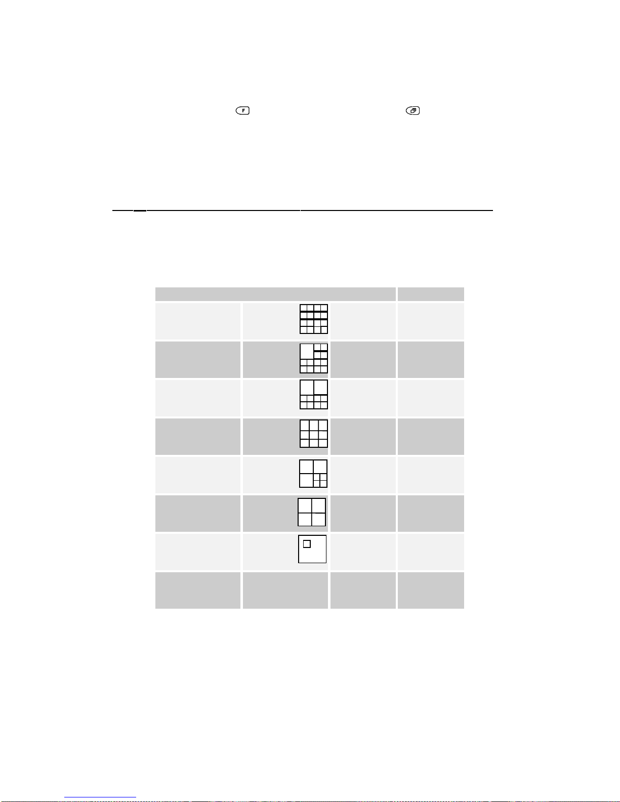
HBZMXSIB/10/16SD-OP-1 Page 21
To Increment/Decrement (dependent on month) the time:
Press the FUNCTION key
followed by the SEQUENCE key .
Caution
Take care not to operate this accidentally because it cannot be undone without
entering the menu system.
2.4 Multi-screen Formats
Depending on the type of multiplexer you have, you can switch your multi-screen
display between the following options using the multi-screen key. The individual
areas of a multi-screen are called cameos.
Multi-screen Notes
16-WAY (4X4) 16-way
multiplexers
only
13-WAY (1X12) 16-way
multiplexers
only
10-WAY (2X8)
9-WAY (3X3)
7-WAY (3X4)
QUAD (2X2)
PIP (1 in 1)
16-WAY
(repeats from
top of list)
Note
The following screen formats are not available in Playback mode:
Mono models: PIP, 7-way, 10-way and 13-way screens
Colour models: 7-way and 13-way screens
Page 98

HBZMXSIB/10/16SD-OP-1 Page 22
2.5 Monitor Outputs
Monitor-B
The Monitor-B monitor always displays analog live, full-screen images of the camera
inputs, regardless of which mode is selected.
Monitor-A
While Recording
On a duplex unit, you can select LIVE or PLAY mode while recording is taking place.
Hence you can select any desired Monitor-A multi-screen output on a duplex unit,
while multiplexed recording takes place on the VCR output. Monitor-A images can be
frozen.
On a simplex unit, Monitor-A only displays analog, full-screen images while RECORD
mode is selected, and displays exactly the same output as on Monitor-B.
Record Speed Indicator
During recording, the multiplexer indicates the speed at which it is recording on
Monitor-A. It uses the same time-format for the indicator as is generally used by time
lapse VCRs. For example, R024 will be displayed to indicate that the unit is
Recording in 24 hour mode. (If the VCR switch input is active, then R EXT will be
displayed.)
On a simplex unit, this indicator will only be seen in RECORD mode. On a duplex
unit, this indicator will be visible in all modes.
Alarm Displays In Record Mode
On a duplex unit you can select LIVE or PLAYBACK modes while recording is taking
place, and so the alarm displays will conform to the LIVE or PLAY modes of
operation.
On a simplex unit in RECORD mode, the Monitor-B and the Monitor-A multi-screen
outputs are the same, and both will automatically switch to a full-screen live display
of a camera in alarm. Multiple simultaneous alarms cause the display to sequence
between alarmed cameras, with a fixed dwell time of 1 second.
Note
During RECORD mode, the alarm image on a simplex unit cannot be frozen on
Monitor-A.
Page 99

HBZMXSIB/10/16SD-OP-1 Page 23
Live Mode
If a multi-screen does not have all the cameras displayed, the system can sequence
all remaining cameras in the last cameo.
You can also select a full-screen digital display of any of the input cameras and a
sequenced display of full-screen cameras.
Sequencing In Cameos
Press SEQUENCE key while in Live multi-screen mode to automatically sequence all
the undisplayed cameras in the lower right cameo.
Automatic Camera Location Memory
If you have set up the camera numbers and locations which are to be displayed in a
particular multi-screen, then the unit will automatically save that selection and will
display the same camera selection and locations each time that particular multiscreen is selected. (This is saved in volatile memory.)
For example, if cameras 9, 4, 7 and 2 are selected for the quad multi-screen, then
whenever you select the quad multi-screen, those cameras will be displayed, and in
the same quadrants as you originally selected.
Automatic Multi-Screen Format Memory
If you switch from a multi-screen display to a full-screen camera image, then when
the MULTI-SCREEN key is next pressed, you will automatically return to the last
multi-screen format that was being viewed.
For example, if you are viewing a 7-way multi-screen and switches the display to a
full-screen display, then if the MULTISCREEN key is pressed later the Monitor-A
display will switch directly back to the 7-way screen format.
Setting Up the Cameras In Monitor-A Multi-screen Displays
Any camera can be displayed in any position in the multiplexer multi-screen displays.
The default multi-screen displays show the cameras in ascending order. In LIVE
mode, you can display one camera in more than one position, while in PLAY mode
each camera can be displayed once only on each multi-screen.
To make it simple for you to select any camera for display in any cameo in a LIVE
multi-screen, the multiplexer uses the concept of Active Cameos.
An active cameo is simply an on-screen indication of which particular cameo will be
affected by the next front panel keystroke. Active cameos are used mainly to give
you a simple way of specifying which camera is to be displayed in which cameo, but
other useful functions such as cameo freeze and zoom to full-screen are also
available. To add a camera to an active cameo, simply press the appropriate camera
key. The selected camera is added to the cameo and the next cameo in the multiscreen becomes the active one.
An active cameo will only be present if you specifically select active cameo mode.
Page 100

HBZMXSIB/10/16SD-OP-1 Page 24
Selecting Active Cameo Mode
Press the ENTER key while displaying any multi-screen. The top left cameo will be
the initial active cameo.
The active cameo is indicated by displaying the camera number and its title in
flashing video.
Ending Active Cameo Mode
The active cameo mode will stay active for about 15 seconds after the last key is
pressed, or until the ENTER key is pressed again to exit the mode. Active cameo
mode will also stop immediately if a new multi-screen display is selected, or if you
switch between LIVE, PLAY and RECORD modes.
Key Functions During ACTIVE CAMEO Mode
Key Function
Arrow key Moves the active cameo around the multi-screen.
Camera key Selects which camera to display in the active cameo.
The active cameo will then automatically advance to the next logical
cameo on the right so that you can easily enter camera numbers in
several cameos without using the arrow keys.
FREEZE key Freezes the cameo.
ZOOM key Switches to a full-screen display of that camera. This will cancel
active cameo mode.
Note
If the ZOOM key is pressed with no active cameo selected, then the display will
switch full-screen to the camera displayed in the top left cameo.
Display formats are operating parameters, not menu selections, and so they are
saved in volatile memory and not in battery backed-up memory.
Resolution of Full-screen displays (Colour models)
You can switch the resolution of digital full-screen displays from ‘frame’ displays to
‘field’ displays on Colour models. The lower resolution ‘field’ displays can result in
less ‘flickering’ on some high contrast camera scenes.
To switch between ‘field’ resolution and ‘frame’ resolution on a full-screen display,
press the camera number key of the camera which is already being displayed fullscreen. The display will toggle its resolution each time the key is pressed.
Note
This is a global system setting, not a camera-by-camera setting.
 Loading...