

Page 1

IP Series Cameras
Installation Manual
Please read this manual before installing your equipment
Page 2
IP Series Cameras Installation Manual
2
TO PREVENT FIRE OR SHOCK HAZARD, DO NOT EXPOSE THIS
APPLIANCE TO RAIN OR MOISTURE
IMPORTANT
The first few pages of these instructions contain important information on safety and product
conformity. Please read, and ensure that you understand this information before continuing.
Page 3

Installation Manual IP Series Cameras
3
CONTENTS
Introduction ............................................................................................................ 4
Product Safety ........................................................................................................ 5
Electromagnetic Compatibility (EMC) .................................................................. 5
EU Conformance Statement ................................................................................. 6
Regulatory Notices ................................................................................................ 6
Unpacking ............................................................................................................... 6
Cautions .................................................................................................................. 7
Connectors and Controls ......................................................................................... 7
Power Supply Connection ....................................................................................... 7
Video Connections ................................................................................................... 8
Lens Selection ......................................................................................................... 8
Lens Connection ...................................................................................................... 9
Focus Adjustment .................................................................................................. 10
Audio Connections ................................................................................................. 10
Alarm Connections ................................................................................................. 11
Serial Connections ................................................................................................. 12
Network Connection ............................................................................................... 12
Switch Settings ...................................................................................................... 13
Programming and Addressing ............................................................................... 13
Specifications ......................................................................................................... 14
Page 4
IP Series Cameras Installation Manual
4
INTRODUCTION
These instructions cover Baxall IP series cameras. Read all of these instructions. Use
them to install the camera and have them available for its lifetime. If you have any problems,
contact Baxall Limited. All IP series cameras are fitted with a Direct Drive (DD) lens connector,
have adjustable back focus and accept C and CS lenses.
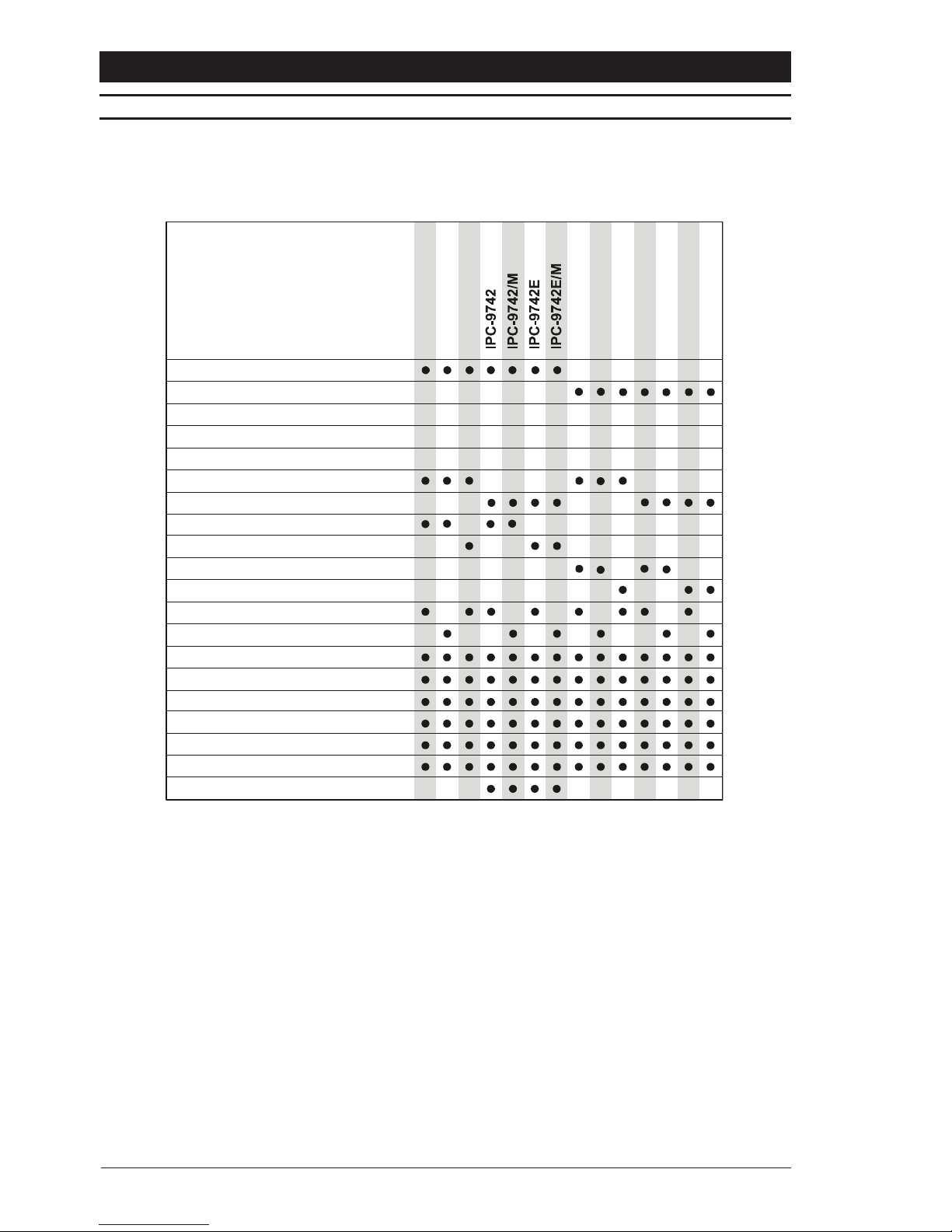
There are a number of variants in the IP series camera range, with 1/2 and 1/3 CCD
monochrome output (CCIR or EIA format) and colour output (PAL or NTSC) models available.
There is also a choice between models configured to use H261 compression and models
that use MJPEG compression. All the variants require an external 12V DC power supply.
The IP series cameras are designed to encode compressed video and transmit the data
over either a 10 or 100 Base-T network at variable bit rates of between 8Kbps and 1.5Mbps.
Using an IP decoder, this data can be converted to an analogue video signal and displayed
on a standard CCTV monitor (H261 compression only). Alternatively, IP series cameras
can be displayed on a PC using the IP PC Viewer.
A serial data channel can be set up to support RS232, RS422 or RS485 operation, allowing
integration with third party equipment. In addition, provision is made for two alarm inputs,
one alarm output, and a bi-directional audio channel (G711 or G728).
Video (H261 or MJPEG) and audio (G711 or G728) options are pre-programmed at
production. However, different software can be downloaded into the camera using the
Video Administrator tool, as described in the IP PC Viewing and Configuration Software
Manual. These downloads are available by contacting Baxall Technical Support.
Option
Mono
Color
Maximum Resolution (TVL)
Sensitivity (lux @ f1.2)
CCD Sensor size
Sony HyperHAD™ CCD
Sony ExviewHAD™ CCD
580 580 480
0.1 0.90.04
1/3“ 1/3“1/2“
IPC-9252
IPC-9313IPC-9313N
PAL
480
0.9
1/3“
NTSC
580
0.1
1/3“
IPC-9252E
CCIR
EIA
580
0.04
1/2“
Adjustable Gamma
Automati c G a i n Co n tr o l O n /O ff
Backlight Compensation On/Off
Direct Drive Auto-Iris connection
Extended IR performance
Electronic Iris On/Off
Video Drive Auto-Iris connection
480
0.4
IPC-9714
IPC-9714N
480
0.4
1/2“ 1/2“
580 580 480480
0.1 0.04 0.9 0.4
1/3“ 1/3“ 1/2“1/2“
H261 Compression
MJPEG Compression
IPC-9252/MIPC-9313/MIPC-9714/
M
580
0.04
1/2“
IPC-9714N/M
0.4
1/2
“
Page 5

Installation Manual IP Series Cameras
5
PRODUCT SAFETY
Installation and servicing is only to be carried out by suitably qualified and
experienced personnel to local or national wiring standards. Failure to do so
can result in death or injury by electric shock.
A means of disconnecting the equipment from the mains supply must be provided
as part of the installation and must be situated close by.
Before undertaking any installation or maintenance, the mains supply must be
disconnected.
Good engineering practice must be carried out at all times and all servicing and
repairs carried out indoors.
All IP series cameras are to be powered with a class 2 power supply.
Do not exceed the voltage and temperature limits given in the specifications.
The IP series camera is fitted with a 1 A (T) 125V time-lag fuse located on the
rear board assembly. Replacement must be with an identical type of fuse.
The IP series range is designed for use in general purpose CCTV applications
and has no other purpose.
Only use your IP series camera in a clean, dry, dust-free environment unless a
suitable protective housing is provided.
Electrical Safety
British Standard BSEN60950:2000 Safety of information technology equipment, including
electrical business equipment.
ELECTROMAGNETIC COMPATIBILITY (EMC)
This is a Class A product. In a domestic environment this product may cause radio
interference in which case the user may be required to take adequate measures.
Radio Frequency Emissions
Federal Communications Commission Code of federal regulations Part 15.
British standard BSEN50081-1:1992 Electromagnetic compatibility - Generic emission
standard.
Part 1. Residential, commercial and light industry British standard BSEN55022:1998 Limits
and methods of measurement of radio disturbance characteristics of information technology
equipment.
Immunity
British Standard BSEN 50130-4:1996 Alarm Systems Part 4 Electromagnetic compatibility.
Product family standard: Immunity requirements for components of fire, intruder and social
alarm systems.
Page 6

IP Series Cameras Installation Manual
6
EU CONFORMANCE STATEMENT
A Declaration of Conformity in accordance with the following EU standards has been
made and is on file at Baxall Limited, Stockport SK6 2SU England.
The manufacturer declares, that the product supplied with this document is complaint with
the provisions of the EMC Directive 89/336 EEC, the CE Marking Directive 93/68 EEC and
all associated amendments.
REGULATORY NOTICES
This device complies with part 15 of the FCC rules. Operation is subject to the following
two conditions:
(1) this device may not cause harmful interference, and
(2) this device must accept any interference that may cause undesired operation.
UNPACKING
Keep your packaging for use if the product is to be stored for an extended period or needs
to be returned for any reason. The packaging should contain:
An IP Series Camera
Panasonic Plug for Direct Drive (DC) Auto-Iris Lenses
Camera Mounting Screws
A 15-Way D-Type Connector
Licence Agreement
These Instructions
Check the product code on the serial number label. If you have an incorrect item or it is
damaged then inform the suppliers and carriers immediately. If this is the case then do not
attempt to use the equipment.
Please read the licence agreement, as by using this product you agree to all of the terms
and conditions contained within it.
Page 7
Installation Manual IP Series Cameras
7
CAUTIONS
In order to avoid damaging the camera note the following points.
1) The camera has threaded mounting points on the top and bottom of the case.
Only use a standard, photographic, mounting-bolt with a 1/4-20 UNC thread.
2) Before fitting the lens make sure that its back will not touch the CCD sensor or
associated components when screwed fully home.
3) Do not touch the image-surface of the sensor. If the sensor is accidentally
touched, only clean it using ethyl alcohol.
4) Do not expose the sensor to direct sunlight as this may impair the performance
of the camera.
5) Only use the camera in a clean, dust-free environment.
6) For outdoor use, an appropriate protective housing conforming to IP65 or UL50
or better must be used.
CONNECTORS AND CONTROLS
(7)
(8)
(
3)
(
2)
(
5)
(
4)
(6)
(9)
(
1)
(10)
Side View
(11)
POWER SUPPLY CONNECTION
IP series cameras operate via an external power supply at 12V DC ONLY. This power
supply must be a Class 2 isolated type and be capable of delivering a current of 1
Amp in normal operation.
The power connector is located on the rear panel of the camera, with the polarity clearly
marked. A green LED is also present on the rear panel, and this lights when the power
supply is connected and switched on.
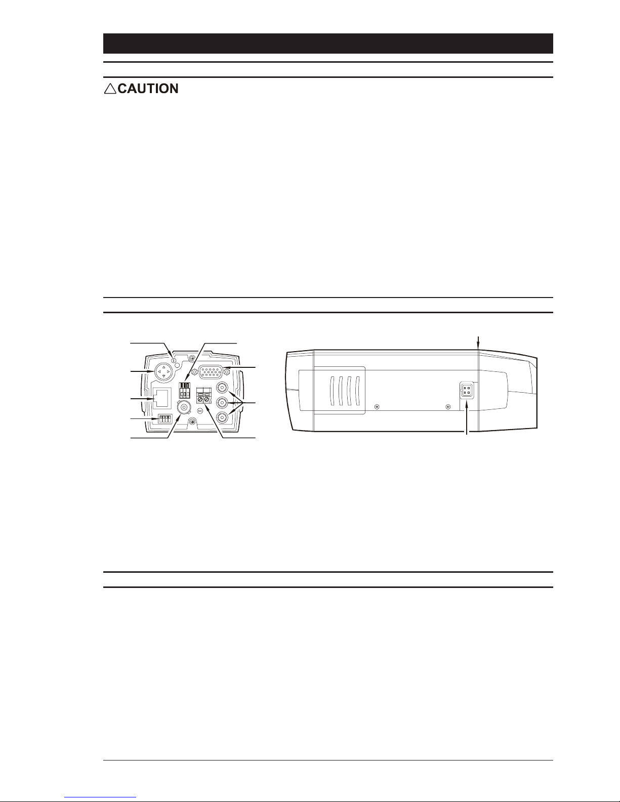
1. Power LED
2. Joystick (no function)
3. RJ45 Ethernet Connector
4. Camera Settings Dip Switches
5. Composite Video Output BNC
6. Video Drive Auto-Iris Lens Connector
7. Serial, Alarms and Audio 15-pin D-type Connector
8. Video Server Inputs
9. Low-Voltage Power Supply Terminals (12V DC)
10. Direct-Drive (DC) Auto-Iris Lens Connector
11. Back-Focus Adjustment Screw
Page 8
IP Series Cameras Installation Manual
8
VIDEO CONNECTIONS
The colour variants in the IP camera range are available with sensors suitable for either
NTSC or PAL format output, and the monochrome variants are available with sensors
suitable for either CCIR or EIA format output. IP series cameras can automatically detect
which type of sensor has been fitted and they will then select the corresponding output
type. To change from PAL to NTSC or from CCIR to EIA, a new sensor board must be fitted
in the factory.
Analogue Inputs
IP series cameras are provided with three auxiliary inputs enabling external analogue video
inputs to be connected. The inputs are terminated by 75W. Care must be taken to ensure
that the inputs are not double-terminated when the equipment is looped in with other
equipment.
The inputs may be a mixture of monochrome or colour.
Analogue Output
A BNC socket is provided on the rear panel for output of a standard composite video signal.
This enables focus and other camera parameters to be set up locally, without connecting to
the network. Alternatively, this output can be used as a conventional composite video output
for use with existing analogue systems.
LENS SELECTION
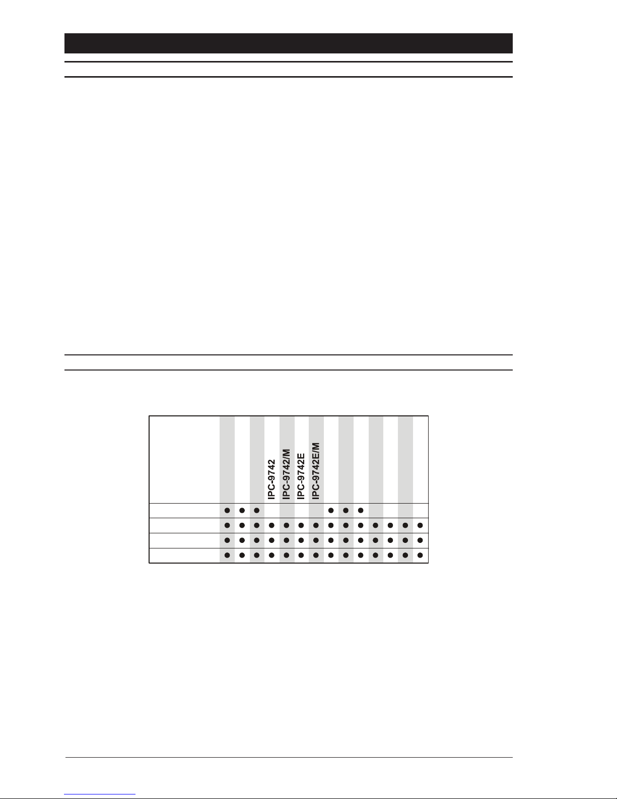
Suitable lens types are C or CS mount in fixed-iris, manual-iris, auto-iris or direct-drive
versions. Sizes are shown below. Cameras are factory set for CS mount lenses.
Lens size
1/3"
1/2"
2/3"
1"
IPC-9252IPC-9252EIPC-9714NIPC-9714IPC-9313NIPC-9313IPC-9252/MIPC-9313/MIPC-9714/MIPC-9714N/
M
Page 9
Installation Manual IP Series Cameras
9
LENS CONNECTION
Fixed and Manual Iris Lenses (for indoor use only) require no wiring connections.
Video Drive Auto-Iris Lenses
Connections for video drive auto-iris lenses are located on the rear of the camera. Connect
lenses to the 3 terminal connector block according to the table below.
Once the lens has been connected, switch the EI and AGC functions off using the dip
switches located on the rear panel of the camera. Referring to the lens instructions, adjust
the lens for optimum picture (video output level of 1V pk-pk), and switch AGC back on.
See page 13 for more details on using the dip switches on the rear of the camera.
Direct Drive Auto-Iris Lenses
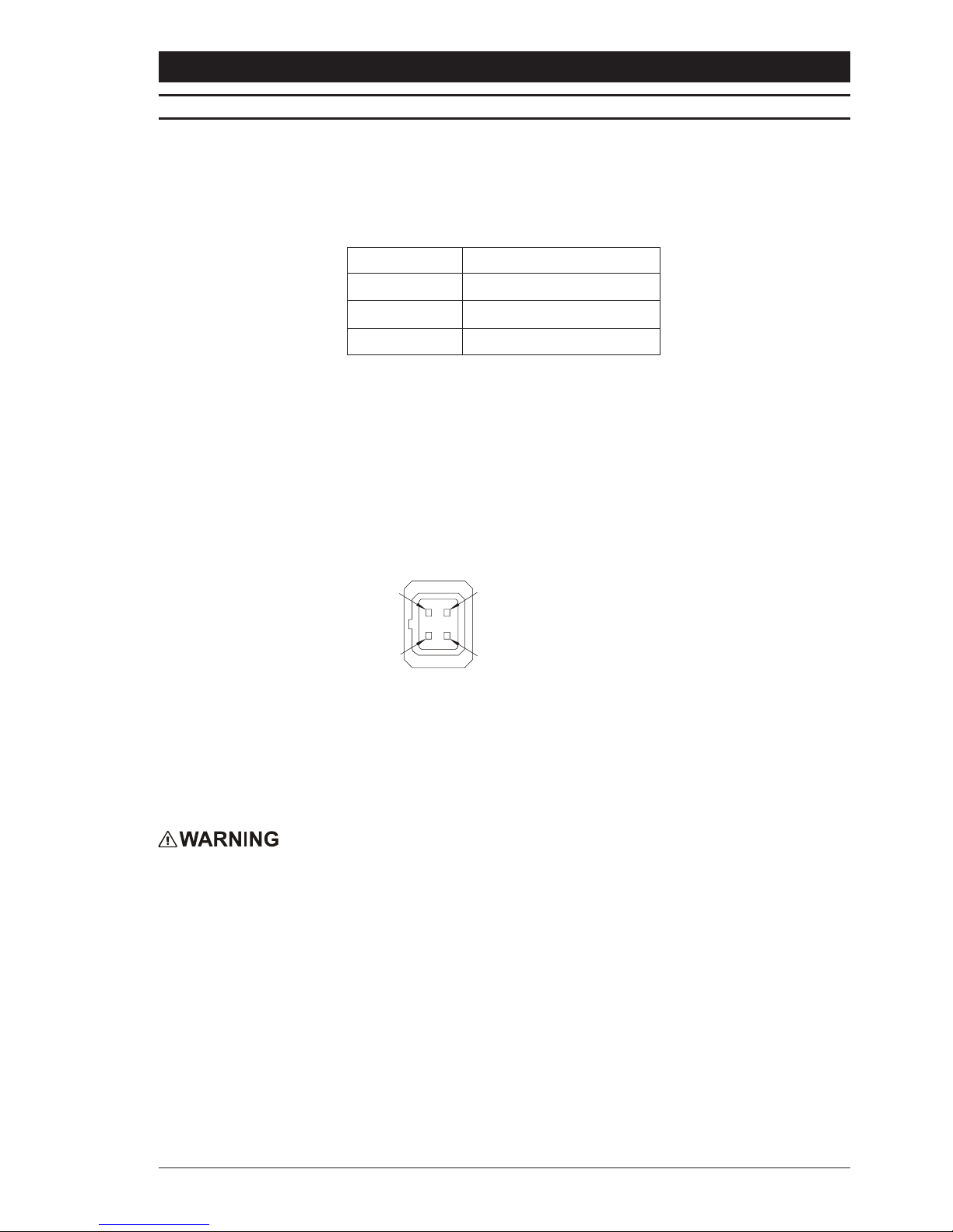
Connect DD lenses to the female 4-pin socket on the side of the camera. If the lens does
not have a DD plug fitted then wire the lens to a suitable plug in accordance with the
diagram below.
1 = Damp
-
2 = Damp
+
3 = Drive
+
4 = Drive
-
1
3
2
4
Once the lens is connected, switch the EI and AGC functions off using the dip switches
located on the rear panel of the camera. Using an appropriate screwdriver, turn the lens
level potentiometer fully clockwise. Next slowly adjust the lens level potentiometer for
optimum picture (video output level of 1V pk-pk), and switch AGC back on.
See page 13 for more details on using the dip switches on the rear of the camera.
Under no circumstances must the power consumption of the rear Video Drive
connector exceed 50 mA or the Direct Drive connector exceed 25 mA.
Connector Description
Red Lens positive supply
Black Lens ground
White Video drive signal
Page 10

IP Series Cameras Installation Manual
10
FOCUS ADJUSTMENT
Turn the back focus adjuster screw on the top of the camera clockwise or anticlockwise to
obtain focus. When the focus is sharp, turn the adjustment screw 2 or 3 turns anticlockwise.
The picture will lose sharpness. Turn the screw clockwise until focus is once again obtained.
If the point of best focus is passed, repeat the procedure. The last turn of the back focus
adjustment screw must always be in a clockwise direction. Do not over turn or force
the back focus mechanism.
Fixed Lenses
Set the lens focus to infinity and view an image greater than 2 metres away. Focus the
image using the back-focus screw. Set the lens focus as required.
Manual Iris Lenses
Open the iris fully and set the lens focus to infinity. View an image greater than 2 metres
away. Focus the image using the back-focus screw. Set the lens focus and iris as required.
Video Drive and Direct Drive Auto-Iris Lenses
Fully open the iris by covering the lens with a suitable neutral density (ND) filter. Set the
lens focus to infinity. View an image greater than 2 metres away. Focus the image using the
back-focus screw. Remove the ND filter and set the lens focus as required.
Zoom Lenses
Set the lens focus to infinity and fully open the iris by covering the lens with a suitable
neutral density (ND) filter. Zoom out to the widest field of vision and view a distant object.
Adjust the back focus screw until the object is in focus. Next, zoom fully in and adjust the
focus of the lens until the object is again focused. Repeat these steps until the full zoom
range may be viewed with the minimum loss of focus.
AUDIO CONNECTIONS
IP series cameras include a mono-channel audio input and output.
The circuitry enables connection of audio equipment to the input channel. This input channel
is pre-programmed to G711 or G728 compression and has a bandwidth of 0.3 3.6 kHz.
The output channel gives a 1V pk-pk output for connection to other audio equipment or the
direct drive of a small loudspeaker.
The audio line in and out connections should be made to the 15-way D-type connector on
the rear of the camera. Pins 5, 10 and 15 should be connected as follows:
Note
The audio line in and out signals are at line level. Connections to PA systems or microphones
may need additional equipment. Please contact your distributor for technical assistance.
Audio Connection
5. Audio In
10. Common
15. Audio Out
5
4
3
2
1
10
98
7
6
15 14 13 12 11
Page 11
Installation Manual IP Series Cameras
11
ALARM CONNECTIONS
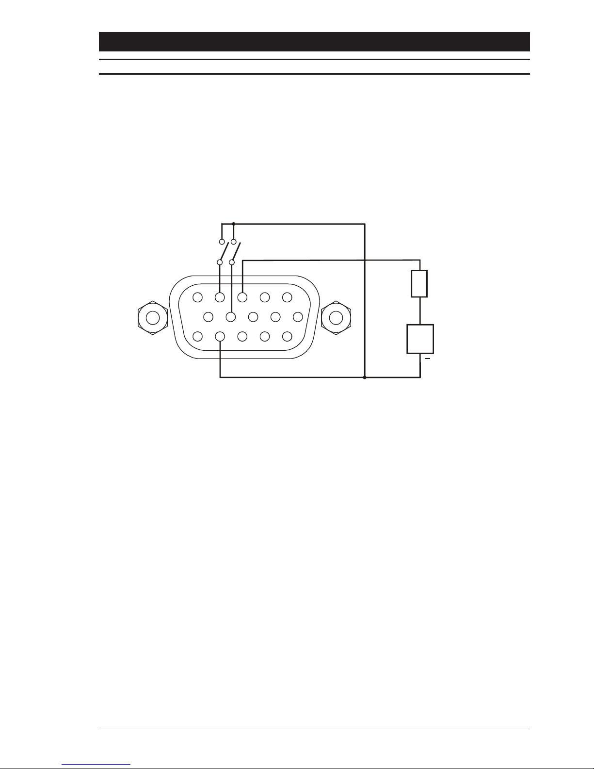
The IP series cameras provides two alarm inputs via internal opto-isolators, and these
inputs can be used to interface to a variety of equipment. The internal resistors are set for
operation with 5V 12V inputs, but inputs operating at 24V or other voltages can be achieved
by adding external padding resistors.
An alarm output is also provided via an internal open collector transistor rated at 24V
250mA. It is suitable for use with driving lamps, alarms and other external equipment.
Alarm inputs and output connections are made to the 15-way D-type connector on the rear
of the camera. Pins 3, 4, 9 and 14 should be connected as follows:
52
1
10
8
7
6
15 13 12 11
+
PSU
ALARM OUTPU
T
(LED, RELAY
LAMPS ETC)
ALARM INPUTS
9
4
3
Connector viewed
from rear of camera
14
Note
In applications where it is required to operate higher-powered equipment, a separate external
interposing relay should be used.
Page 12
IP Series Cameras Installation Manual
12
PIN RS232 RS422 RS485
1 RTS Tx+ Tx+
2Rx Rx- Rx-
6 Tx Tx- Tx-
7 CTS Rx+ Rx+
8 Ground Not Used Not Used
SERIAL CONNECTIONS
IP series cameras can be configured for connection to RS232, RS422 or RS485 networks.
These serial connections are made to the 15-way D-type connector on the rear of the
camera. Pins 1, 2, 6, 7 and 8 should be connected as follows:
For RS485 connections, the installer must also link pin 1 to pin 7, and pin 2 to pin 6 on
the back of the connector itself.
Biasing and Termination
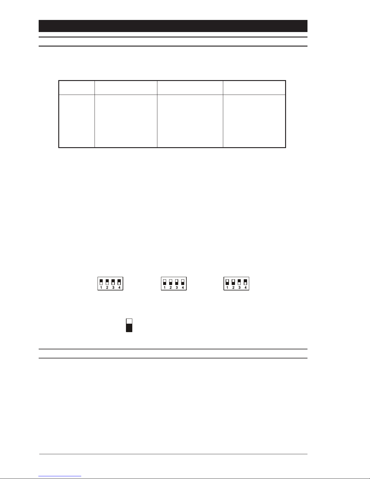
It may then be necessary to apply biasing and termination to these networks. This can be
implemented in one of two ways:
Through the use of internal dip switches.
By adding resistors to the serial connector externally if it is not possible or desirable to
remove the camera lid.
To access the internal resistors the camera lid must be removed. The resistors are located
at the bottom edge of the IP interface card (P1102 the longer of the two side cards).
The internal switch settings are shown below:
White indicates switch position
ON
RS485 Terminatio
n
and Biasing ON
ON
RS422 Termination
and Biasing ON
ON
R
S232 Termination
and Biasing OFF
NETWORK CONNECTION
A shielded RJ45 Ethernet connector is provided on the rear of the camera for direct interface
to the network. The connector is suitable for use on both 10 and 100 Base-T networks.
Internal line terminations for a screened Cat 5 cable are also provided.
Page 13
Installation Manual IP Series Cameras
13
SWITCH SETTINGS
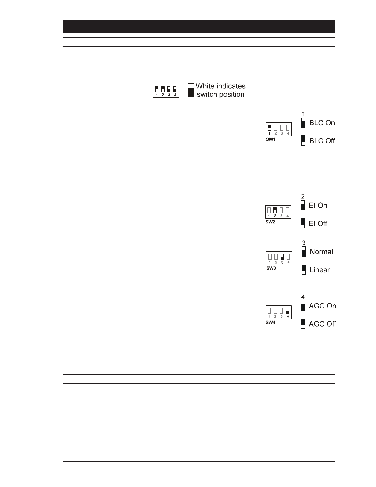
There are four function switches on the rear panel of the IP series cameras that control the
Backlight Compensation (BLC), Electronic Iris (EI), gamma correction and Automatic Gain
Control (AGC) functions.
Backlight Compensation (BLC)
Backlight compensation operates by enhancing objects in the
centre of the scene which would previously have been in
silhouette. The BLC feature is turned ON or OFF using dip switch
number 1. Default setting is OFF.
BLC will only function with a manual iris lens when the Electronic
Iris feature is switched ON. For direct drive and video drive auto-
iris lenses, BLC will still function even though the Electronic Iris
feature is switched off.
Electronic Iris (EI)
The Electronic Iris (EI) feature compensates for excessive light
levels by automatically adjusting the shutter speed of the camera.
Select ON or OFF using dip switch number 2. The default setting
is OFF.
Gamma
Dip switch number 3 is used to select between the two available
gamma correction options. Use the switch to select NORMAL
(0.45), which provides increased visibility within the darker areas
of a scene, or LINEAR (1.0) for a more linear response. The
default setting is NORMAL.
Automatic Gain Control (AGC)
The Automatic Gain Control feature can improve picture quality
when the level of scene illumination is low. Select ON or OFF
using dip switch number 4. For most applications, the AGC feature
should be ON and is therefore the default setting.
Synchronisation
The camera is set to INTERNAL, which locks the frame rate to a frequency generated by
an internal crystal.
PROGRAMMING AND ADDRESSING
IP series cameras are pre-programmed with the appropriate video and audio software to
suit the application.
MAC Address
This is pre-programmed at the factory and cannot be altered by the customer.
IP Address
The default IP address programmed into the unit is 10.1.166.1 with a subnet mask of
255.224.0.0. This may be changed using the Video Administrator tool, as described in the
IP PC Viewing and Configuration Software Manual (available from www.baxall.com).
Page 14

IP Series Cameras Installation Manual
14
SPECIFICATIONS
Description
Video camera with three auxiliary video inputs, duplex audio, full duplex data communications
and integrated Ethernet connection.
Video Format
Pre-programmed with H261 or MJPEG compression. Software downloads available to alter
format.
Video Resolutions
Interchangeable choice of resolutions from 704 x 576 pixels to 176 x 144 pixels.
4CIF: 704 x 576 pixels
VGA: 640 x 480 pixels
CIF: 352 x 288 pixels
SIF: 352 x 240 pixels
QCIF: 176 x 144 pixels
(Maximum Resolution TVL as stated on page 4 possible using 4CIF setting)
Video Performance
Up to 25/30 frames per second at CIF resolution with H261; up to 15 frames per second at
CIF resolution with MJPEG.
Auxiliary Video Inputs
Three 1V pk-pk inputs terminated in 75W.
Auxiliary Video Output
1V pk-pk composite video.
Audio
Bi-directional. Pre-programmed to G711 or G728 compression. Software downloads
available to alter format.
Network Protocols
Internet IP, TCP, UDP, ICMP, ARP and IGMP with configuration via administration tools.
Interfaces
LAN data rate: 8 Kbps up to 1.5 Mbps.
Data Interface: RS232, RS422 or RS485 at 120 bps - 115 Kbps.
Alarm Interface: 2 inputs and 1 output. Inputs opto-isolated, TTL level. Outputs via open
collector 24V, 250mA.
Audio interface: Line-in and line-out, Bandwidth 0.3-3.6 kHz, 1V peak-peak.
Temperature
Operating: -10
O
C to +50OC (14OF to 122OF)
Storage: -10
O
C to +70OC (14OF to 158OF)
Relative Humidity
Operating: 20% - 80% non-condensing; Storage: 20% - 90% non-condensing
Power Consumption
10W Max
Power Supply
12V DC (+/-10%)
Supports MJPEG only
Supports H261 and MJPEG
Page 15

Installation Manual IP Series Cameras
15
Page 16

HB-IP-CAMERA-2 Issue 2 06/03
Baxall Limited, Stockport, England.
Visit our web sites at http://www.baxall.com and http://www.baxallnetworks.com
Baxall Limited reserve the right to make changes to the product and
specification of the product without prior notice to the customer.
 Loading...