

Page 1
HYPER-D Series Cameras
Installation Instructions
Please read these instructions first!
Page 2

Hyper-D Series Installation Instructions
IMPORTANT
The first few pages of these instructions contain important information on safety and product
conformity. Please read, and ensure that you understand this information before continuing.
2
Page 3
Installation Instructions Hyper-D Series
INTRODUCTION
These instructions cover Baxall Hyper-D series cameras. Read all of these instructions.
Use them to install your camera and have them available for its lifetime. If you have any
problems, contact Baxall Limited.
3
Page 4
Hyper-D Series Installation Instructions
PRODUCT SAFETY
• Installation and servicing is only to be carried out by suitably qualified and
experienced personnel to local or national wiring standards.
• Good engineering practice must be carried out at all times and all servicing and
repairs carried out indoors.
• Hyper-D series cameras are to be powered with a class 2 power supply.
• Under no circumstances must the power consumption of the Auto Iris connector
exceed 50 mA or the Direct Drive connector exceed 25 mA.
• The Hyper-D range is designed for use in general purpose CCTV applications
and has no other purpose.
• Only operate your camera between the temperatures of -10
O
C and +50OC.
In order to avoid damaging the camera note the following points.
1) Before fitting the lens make sure that its back will not touch the sensor or
associated components when screwed fully home.
2) Do not touch the image-surface of the sensor. If the sensor is accidentally
touched, only clean it using ethyl alcohol.
3) Do not expose the sensor to direct sunlight as this may impair the performance
of the camera.
4) For outdoor use, an appropriate protective housing conforming to IP65 or UL50
or better must be used.
MANUFACTURER’S DECLARATION OF CONFORMANCE
The manufacturer declares that the equipment supplied with this manual is compliant with
the essential protection requirements of the EMC directive 89/336/EEC and the CE Marking
Directive 93/68 EEC. The equipment conforms to the requirements of standards
BSEN61000-6-3:2001 for Emissions, BSEN50130-4:1996 (with amendments A1 and A2)
for Immunity and BSEN60950:2002 for Electrical Equipment Safety.
ELECTROMAGNETIC COMPATIBILITY (EMC)
This is a class A product. In a domestic environment this product may cause radio
interference in which case the user may be required to take adequate measures.
This product is intended solely for use in general CCTV applications.
The product must be installed and maintained in accordance with good installation practice
to enable the product to function as intended and to prevent problems. Refer to your agent
for installation guidance.
4
Page 5
Installation Instructions Hyper-D Series
CONNECTORS AND CONTROLS
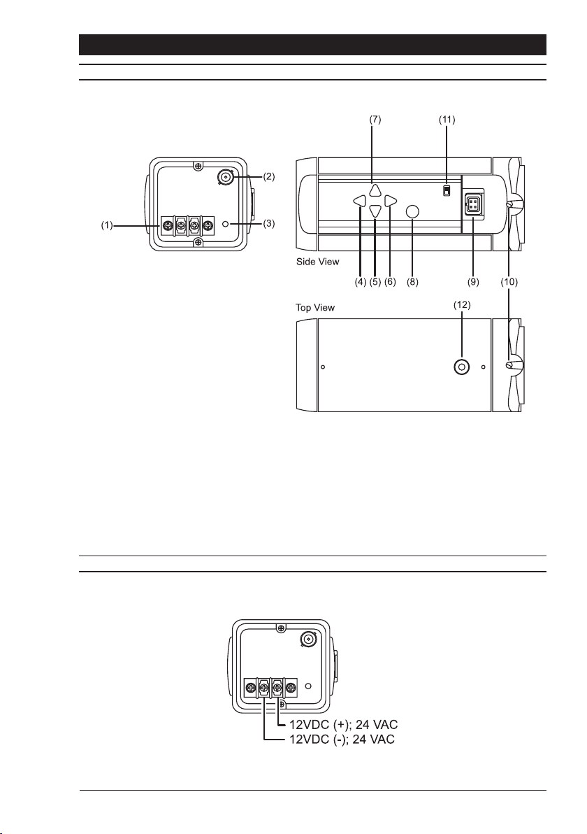
1. Low-voltage power supply terminals
2. Composite video output BNC
3. Power LED
4. Decrease parameter button
5. Menu down button
6. Increase parameter button
7. Menu up button
8. Enter button
9. DD/Video Lens conector
10.Back focus adjustment screws
11.Video format selector switch
12.1/4-20 UNC mounting bush (top and bottom)
Figure 1 Connectors and Controls
POWER SUPPLY CONNECTION
The power supply must be a class 2 isolated type. The green POWER LED on the rear
panel indicates when power is connected.
5
Page 6
Hyper-D Series Installation Instructions
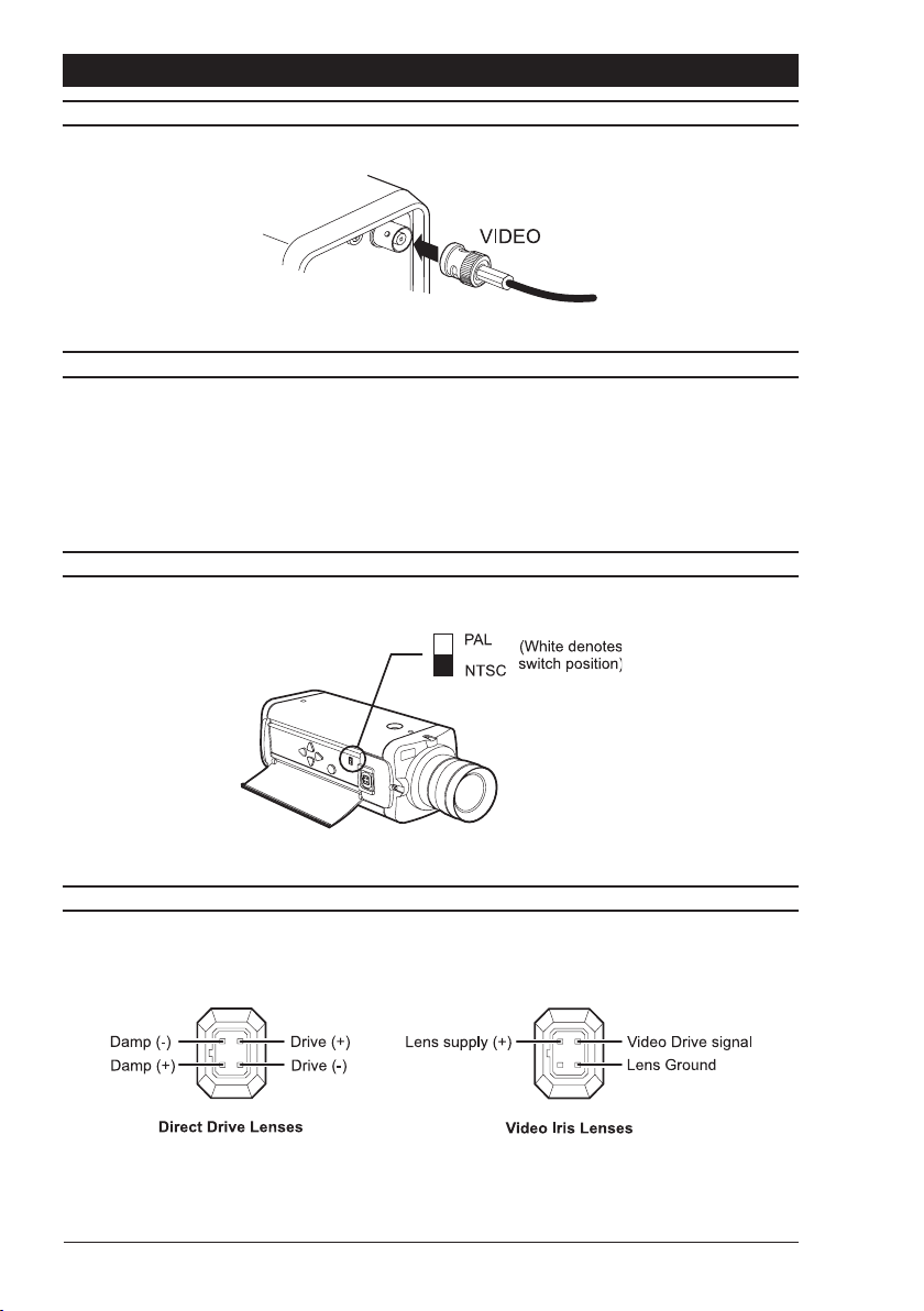
VIDEO CONNECTION
FOCUS ADJUSTMENT
Turn the back focus adjuster screw (10, figure 1) clockwise or anticlockwise to obtain
focus. When the focus is sharp, turn the adjustment screw 2 or 3 turns anticlockwise. The
picture will lose sharpness. Turn the screw clockwise until focus is once again obtained. If
you pass the point of best focus, repeat the procedure. The last turn of the back focus
adjustment screw must always be in a clockwise direction. Do not ‘over turn’ or force
the back focus mechanism.
VIDEO FORMAT SELECTOR
The video format switch is used to select the video format required.
LENS CONNECTIONS
Connect the auto iris lens to the 4-pin iris drive connector located on the side of the camera.
Pin connections for the iris drive connector are as follows:
(Diagram shows connector view)
6
Page 7
Installation Instructions Hyper-D Series
MENU SYSTEM
Hyper-D series cameras utilise a menu system to facilitate setup and adjustment. The
buttons used to access and navigate the menu are located behind the flap on the side of
the camera.
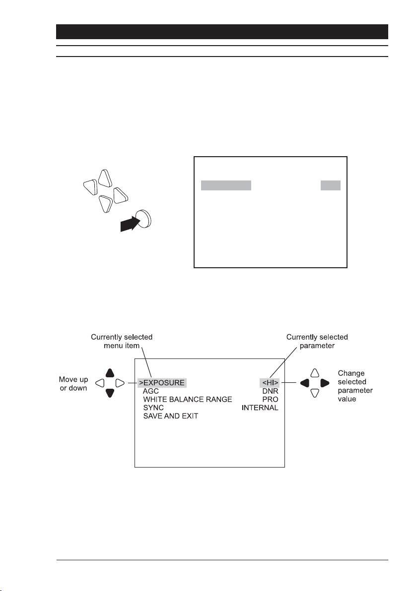
Entering the Menu System
To enter the menu system, press and hold the Enter button (8, figure 1) for approximately
two seconds. A menu similar to the one shown below will be displayed on the monitor.
> EXPOSURE <HI>
AGC DNR
WHITE BALANCE RANGE PRO
FLUORESCENT OFF
SYNC INTERNAL
SAVE AND EXIT
Navigating the Menu System
Use the direction buttons to navigate the menu, and to select parameters.
Exiting the Menu System
The menu system can be exited by selecting SAVE AND EXIT with the up/down menu
buttons and then pressing the Enter button. Any changes made while within the menu
system will be saved. The menu system will be automatically exited if a key is not pressed
for 2 minutes. Any changes made will not be saved should the menu system time-out.
7
Page 8
Hyper-D Series Installation Instructions
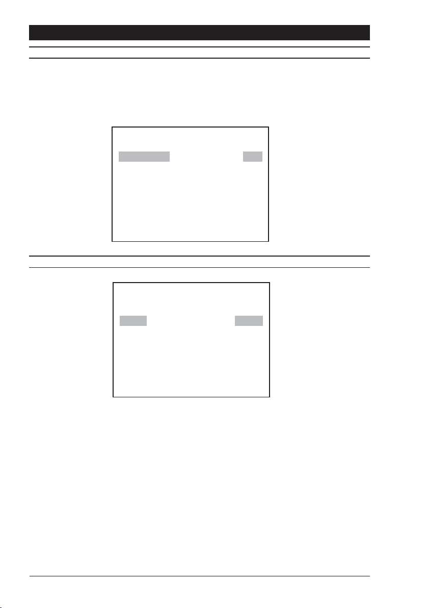
HI (default)
Maintains optimum contrast in the darker portions of a wide dynamic scene.
LOW
Maintains optimum contrast in the brighter portions of a wide dynamic scene.
> EXPOSURE <HI>
AGC DNR
WHITE BALANCE RANGE PRO
FLUORESCENT OFF
SYNC INTERNAL
SAVE AND EXIT
EXPOSURE HI
> AGC <DNR>
WHITE BALANCE RANGE PRO
FLUORESCENT OFF
SYNC INTERNAL
SAVE AND EXIT
MODE
AGC
DNR (default)
This setting has a maximum gain of 24dB. DNR is a Digital Noise Reduction system that
reduce AGC noise by means of a field integration algorithm. A consequence of DNR is that
moving objects can appear blurred at very low light levels.
LOW
This setting limits the gain to 7dB. Setting the AGC to LOW reduces the camera’s
performance at low light, but improves image quality in bright conditions. This is the preferred
setting for well-lit scenes.
MOTION
This setting has a maximum gain of 24dB. This setting does not use DNR at high gain. The
images are sharper than DNR but the visible gain in the image is greater.
8
Page 9
Installation Instructions Hyper-D Series
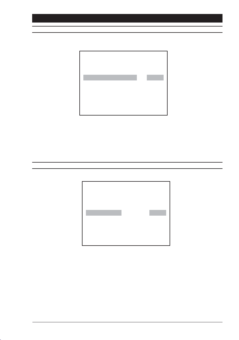
WHITE BALANCE RANGE
This menu is used to adjust the camera’s white balance to compensate for different lighting
types.
EXPOSURE HI
AGC DNR
> WHITE BALANCE RANGE <PRO>
FLUORESCENT OFF
SYNC INTERNAL
SAVE AND EXIT
PRO (default)
This setting limits the white balance range to 2800 - 6500K. This provides a more accurate
colour rendition.
WIDE
This setting extends the white balance range to 2500 - 9500K.
FLUORESCENT
EXPOSURE HI
AGC DNR
WHITE BALANCE RANGE PRO
> FLUORESCENT <OFF>
SYNC INTERNAL
SAVE AND EXIT
ON
Reduces colour rolling that may occur under some types of fluorescent lighting. For best
results, line lock synchronisation is recommended. If line lock synchronisation is not possible,
an auto-iris lens should be used.
OFF (default)
The default setting maximises dynamic range.
9
Page 10
Hyper-D Series Installation Instructions
MAIN MENU - SYNC
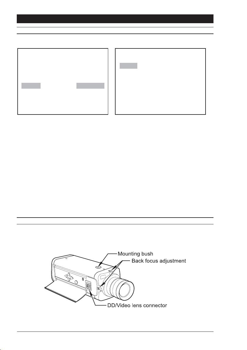
This menu item is used to select the way the camera maintains frame synchronisation.
Linelock Manual Set
EXPOSURE HI
AGC DNR
WHITE BALANCE RANGE PRO
FLUORESCENT OFF
> SYNC <INTERNAL>
SAVE AND EXIT
> Phase |–|–|–|–|–|–|–|–|–|–|
0 606 624
<<Previous Page
|
Internal (default)
For internal synchronisation.
LL-Phase 1, LL-Phase 2, LL-Phase 3
Used when synchronising multiple cameras in a three-phase installation. Each setting has
O
a 120
offset.
LL-Manual
Selecting LL-Manual will open the Linelock Manual Set menu. Use the left/right arrow keys
to manually set the phase (0 to 624).
Note: Line-lock synchronisation may cause some issues with on screen displays. In these
circumstances the camera should be set to internal synchronisation.
MOUNTING
Mounting points (12, figure 1) are provided on the top and bottom of the camera and are
used to mount the camera on a bracket or tripod. Only use standard, photographic 1/4-20
UNC mounting bolts.
10
Page 11
Installation Instructions Hyper-D Series
SPECIFICATIONS
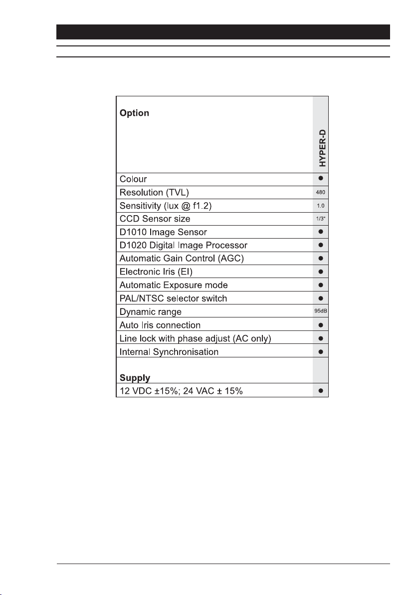
Horizontal resolution >480 TVL
Vertical resolution >400 TVL
Dynamic range 95 dB (14-bit) typical; 120 dB max.
Video Output Composite 1V pk-pk 75 Ohm
Pixel type DPS™ technology
Image size 6.3mm diagonal (type 1/3”)
Sensor array size 5.04mm (H) x 3.78mm (V)
Pixel size 7µm x 7µm
Picture elements total: 742 (H) x 554 (V) effective: 720 (H) x 540 (V)
Power supply 12VDC ± 15%; 24VAC ± 15%
Power consumption <5 W
Weight 0.55 kg
Operating temperature -10 to +50° C (14 to 122° F)
Operating humidity 20 to 80% RH (non-condensing)
Storage temperature -10 to +70° C (14 to 158° F)
Storage humidity 20 to 90% RH (non-condensing)
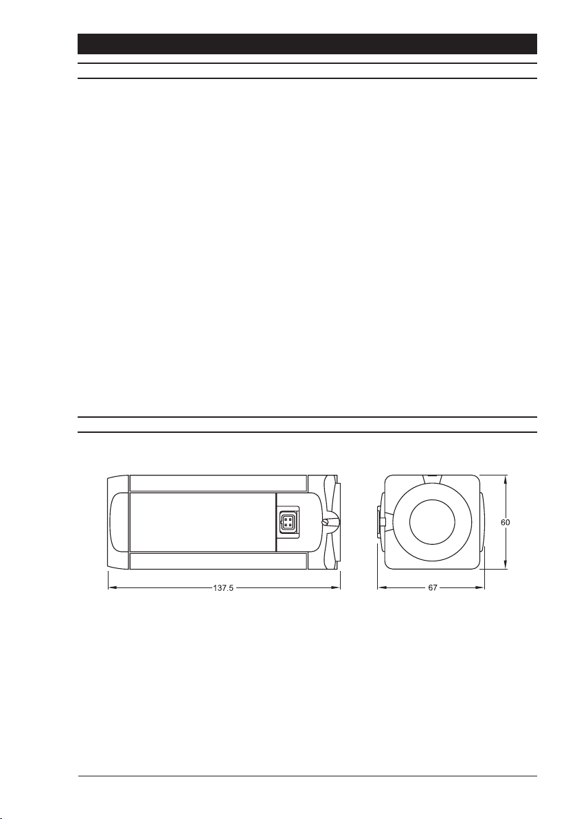
DIMENSIONS
11
Page 12

Baxall Limited, Stockport, England. Visit our Web site: http://www.baxall.com
Baxall Limited reserve the right to make changes to the product and
specification of the product without prior notice to the customer.
HB-HYPER-D-2 Issue 2 07/04
 Loading...