

Page 1

Read these instructions first!
X Series DSP Cameras
Installation Instructions
Page 2
Page 2
X Series DSP Cameras Installation Instructions
INTRODUCTION
These instructions cover Baxall X series cameras. Read all of these instructions. Use them to
install your camera and have them available for its lifetime. If you have any problems, contact
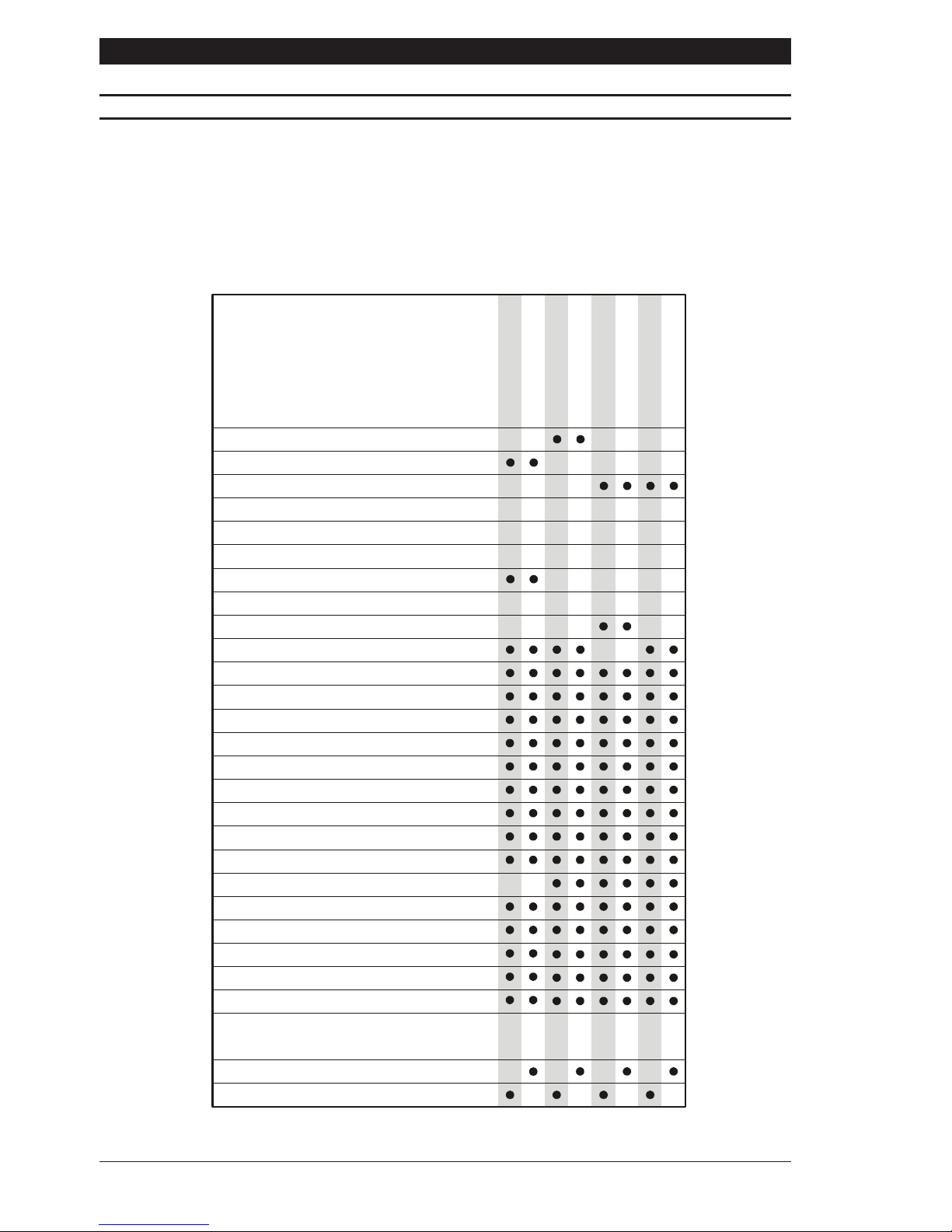
Baxall Limited. Note that not all cameras have all of the features described in this manual. Refer
to the table below for the features of individual cameras. All Baxall X series cameras are fitted
with a Direct Drive (DD) lens connector, have adjustable back focus and accept C and CS
lenses.
Option
Mono
Colour
Colour/Mono auto-switching
Resolution (TVL)
Colour sensitivity (lux @ f1.2)
Mono sensitivity (lux @ f1.2)
Extended IR Performance
CCD Sensor size
Adjustable Gamma (0.45 and 1.0)
Sony EXviewHAD CCD
Sony HyperHAD CCD
Automati c Gain Contr o l (AGC)
AGC on/off
Backlight Compensation (BLC)
Eight BLC Windows
Manual Shutter
Flickerless mode
Electronic Iris (EI)
EI on/off
4 Colour Balance modes*
Auto Iris connection
Genlock
Line lock with phase adjust (AC only)
Peak White Inversion (PWI)
Adjustable PWI Threshold
570570 480 480 570 480570 48
0
0.040.04
0.4 0.4 0.75 1.5
0.4
0.75 1.5
0.080.08
0.
4
1/2“ 1/2“ 1/2“ 1/2“ 1/2“ 1/2“1/2“ 1/2
“
Supply
11 - 40 VDC; 12 - 30 VAC
98 - 260 VA C ± 10%
CDX9742/LV
CDX9742
CDX9714
CDX9714/LV
CDX9772
CDX9772/WF
CDX9772/LV
CDX9772/LV/WF
* 4 Modes = Auto Tracing (ATW), Indoor, Outdoor and Fluorescent
Page 3

Page 3
Installation Instructions X Series DSP Cameras
PRODUCT SAFETY
Installation and servicing is only to be carried out by suitably qualified and
experienced personnel.
Mains cameras contain hazardous voltages
Do not remove covers as there is a risk of injury or death by electric shock.
Cameras connected to mains supplies must be earthed.
Only power low voltage cameras from a class 2 isolated power supply.
The Baxall X series camera range is designed for use in general purpose CCTV applications
and has no other purpose. Only operate your camera between the temperatures of -10
O
C and
+50OC. Do not operate your camera outside its specified power supply range. Baxall X series
cameras must only be used in clean, dry, dust-free environments unless housed in a suitable
protective housing to IP65 or better.
ELECTROMAGNETIC COMPATIBILITY (EMC)
This is a class A product. In a domestic environment this product may cause radio
interference in which case the user may be required to take adequate measures.
This product is intended solely for use in general CCTV applications.
The product must be installed and maintained in accordance with good installation practice to
enable the product to function as intended and to prevent problems. Refer to Baxall Limited for
installation guidance.
MANUFACTURERS DECLARATION OF CONFORMANCE
The manufacturer declares that the equipment supplied with this manual is compliant with the
essential protection requirements of the EMC directive 89/336 and the Low Voltage Directive
LVD 73/23 EEC. Conforming to the requirements of standards EN 55022 for emissions, IEC801
parts 2, 3 and 4 for immunity and EN 60950 for Electrical Equipment safety.
Page 4

Page 4
X Series DSP Cameras Installation Instructions
CAUTIONS
In order to avoid damaging your camera, note the following points.
1) The camera has threaded mounting points on the top and bottom of the case.
Only use a standard, photographic mounting bolt with a 1/4-20 UNC thread.
2) Before fitting the lens, make sure that its back will not touch the CCD sensor or
associated components when screwed fully home.
3) Do not touch the image surface of the sensor. If the sensor is accidentally
touched, only clean it using isopropanol.
4) Do not expose the sensor to direct sunlight as this may impair the performance
of the camera.
POWER SUPPLY
Baxall X series cameras are available in AC mains and AC and DC low voltage types. The
voltage required to operate the camera is clearly marked on the rear panel of the
camera. The green POWER LED on the rear panel indicates that power is connected. Only
power low voltage cameras from a class 2 isolated power supply. The power
consumption of a Baxall X series camera is less than 5 Watts.
Mains power supply
Cameras that are intended to operate directly from the mains supply are fitted with a nondetachable power supply cord. The voltage of operation is clearly marked on the rear panel of
the camera. Generally this is 98 - 260V AC at 50Hz. REFER TO THE WIRING INSTRUCTION
LABEL ATTACHED TO THE SUPPLY CORD and terminate the cord with the appropriate mains
plug fitted with a 3A fuse. MAINS CAMERAS MUST BE CONNECTED TO A PROTECTIVE
EARTH. Ensure that a secure means of isolation from the mains is provided for the camera in
accordance with the national wiring regulations of the country of installation.
Auto-switching power supply
Cameras fitted with an automatic selecting power supply operate between 11-40V DC and
12-30V AC. Connections and polarity are indicated above the screw terminals on the rear
panel. The power supply must be a class 2 isolated type.
VIDEO CONNECTIONS
To obtain a video output, connect a video coaxial cable terminated with a 75W BNC connector
to the BNC socket marked VIDEO OUT on the rear of the camera.
On selected cameras, a means of external synchronisation may be provided - see the table on
page 2 for details. For external synchronisation, connect a video coaxial cable terminated with
a 75W BNC connector to the socket marked GENLOCK on the rear of the camera. The GENLOCK
facility synchronises to either a 1V peak-to-peak video signal or a standard sync plus blanking
signal. A signal connected to the GENLOCK input automatically overrides all other synchronisation
settings.
On colour cameras, the genlock facility locks the lines and not the subcarriers together.
Page 5
Page 5
Installation Instructions X Series DSP Cameras
FUNCTION SWITCHES
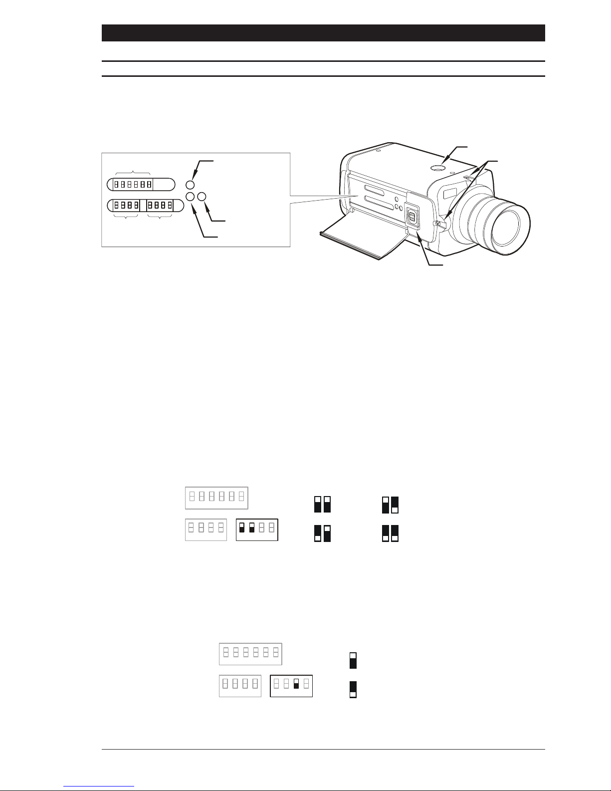
On the side of the camera is a hinged flap. The hinged flap covers a lens level potentiometer, the
Peak White Inversion threshold potentiometer, the BLC window activation button and three
banks of function switches.
DD lens
connector
Mounting bush
Back focu
s
adjustme
nt
SW2 SW3
PWI Threshold
BLC Window On
Lens Level
SW1
Switch Naming Conventions
The DIP switches located under the hinged flap are in three banks SW1, SW2 and SW3.
Throughout this manual, switches are referenced in the following manner: SW1-3 which
corresponds to switch number 3 of switch bank 1.
Colour Balance
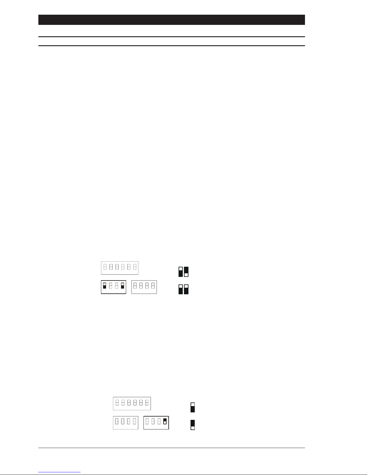
There are four colour balance modes selected by dip switches SW3-1 and SW3-2. For the
majority of applications the Auto setting will provide excellent colour rendition and is the default
setting. For applications where the illumination is predominantly daylight, the Outdoor setting
may provide improved colour rendition over Auto. Where a mixture of illuminations such as
tungsten, fluorescent and daylight exist, the Indoor setting may provide the best colour
rendition. Where fluorescent lighting is predominant use the Fluorescent setting.
Gamma
There are two different levels of Gamma selected by dip switch SW3-3. Choose between
Normal (0.45) to provide increased visibility in dark areas of the scene, or Linear (1.0). The
default setting is Normal.
SW1
SW2
SW3
1
1
1
2
2
2
3
33
4
44
56
AUTO
INDOOR
OUTDOOR
FLUORESCEN
T
1122
SW1
SW2
SW3
1
11
2
22
3
3
3
4
44
56
NORM (0.4
5)
LIN (1.0)
3
Figure 1
Page 6
Page 6
X Series DSP Cameras Installation Instructions
FUNCTION SWITCHES
AGC (Automatic Gain Control)
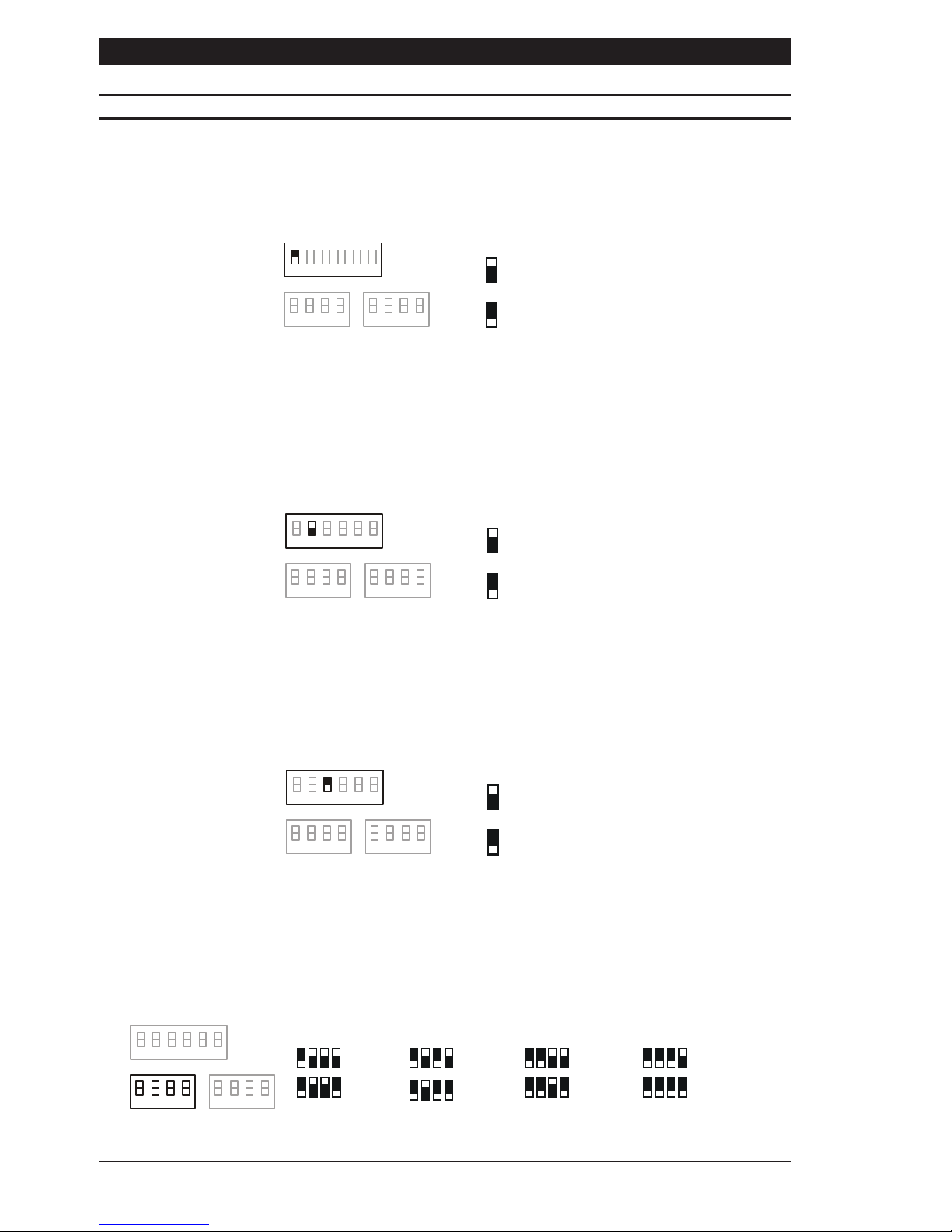
The Automatic Gain Control feature can improve picture quality when the level of illumination is
low. Select ON or OFF using dip switch SW1-1. For most applications, the AGC feature should
be ON and is therefore the default setting.
LL-PH (Line Lock, Phase Adjust)
The Line Lock, Phase Adjust feature is selected by dip switch SW1-2. Choose FIX (fixed) or
ADJ (adjustable). Both settings are line-locked however, the ADJ setting allows ±120
O
phase
adjustment via the potentiometer located on the rear of the camera. The ADJ mode should be
used when cameras are connected to different mains supply phases (R, Y, B). Default setting
is FIX.
SYNC (Synchronisation)
The Synchronisation feature is selected using dip switch SW1-3. Choose L/L (Line-Lock) or
INT (internal). L/L locks the frame rate to the mains so that cameras are triggered at the same
point on the mains supply AC cycle. INT locks the frame rate to the internal oscillator of the
camera. The default setting is L/L.
Shutter speed switches
Shutter speeds are selected with dip switches SW2-1, SW2-2, SW2-3 and SW2-4. Dip switch
SW2-1 must be down to enable manual shutter speed selection. For EI, BLC and Flickerless
functions, switch SW2-1 must be up.
SW1
SW2 SW3
1
11
2
22
3
33
4
44
56
AGC OF
F
AGC ON
1
SW1
SW2 SW3
1
11
2
22
3
33
4
44
56
FI
X
AD
J
2
SW1
SW2 SW3
1
11
2
22
3
33
4
44
56
IN
T
L/
L
3
SW1
SW2
SW3
1
1
1
2
2
2
3
3
3
4
4
4
56
1/4,0001/1,0001/2501/50
1
1/10,00
0
2341
1/2,000
2341
1/500
234
1
1/100
234
Page 7
Page 7
Installation Instructions X Series DSP Cameras
FUNCTION SWITCHES
EI (Electronic Iris)
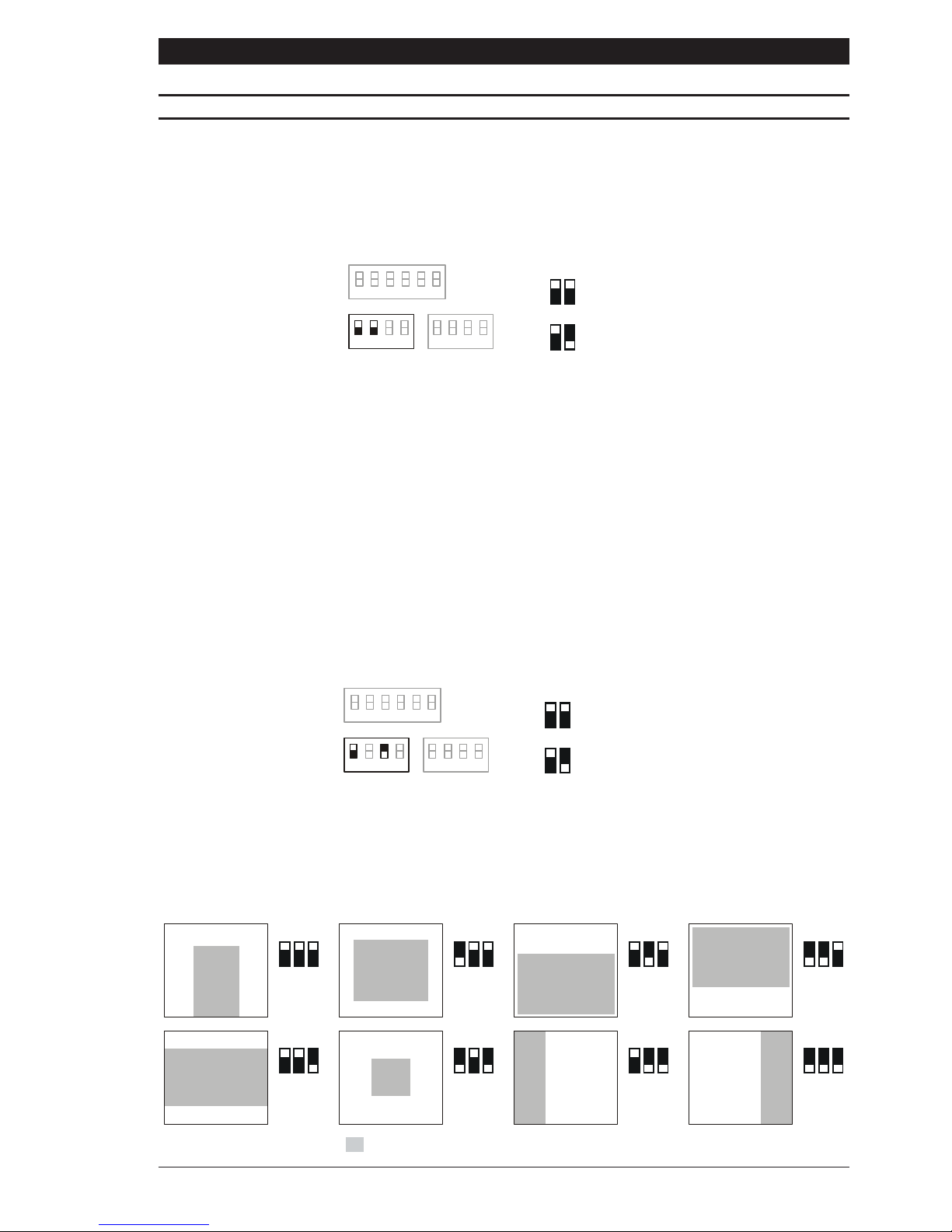
The EI (Electronic Iris) feature compensates for excessive light level by automatically adjusting
shutter speed. Selecting Electronic Iris disables manual shutter speed selection. The Electronic
Iris setting must not be used when the camera is set to Flickerless mode. The default setting is
Electronic Iris ON.
BLC (Back Light Compensation)
The backlight compensation feature can be used to eliminate the effect of an area of strong
background lighting in a scene. If a strong background light such as a window exists in a
scene, the camera will try to compensate for it by reducing the overall exposure. This would
mean that the areas surrounding the window would become too dark.
By using the backlight compensation feature, it is possible to select areas of the scene which
may be used to control the exposure. Typically, the object of interest lies in the centre of the
scene and this is the area normally used to calculate the exposure. The edges, where strong
backlighting is likely to be, are ignored.
The BLC feature is switched ON or OFF using switch SW2-1 and SW2-3. Switch SW2-1 must
be up. Default is OFF. BLC will only function with a manual iris lens when the Electronic Iris
feature is switched on. For direct drive and auto iris lenses, BLC will still function even though
the Electronic Iris feature is switched off.
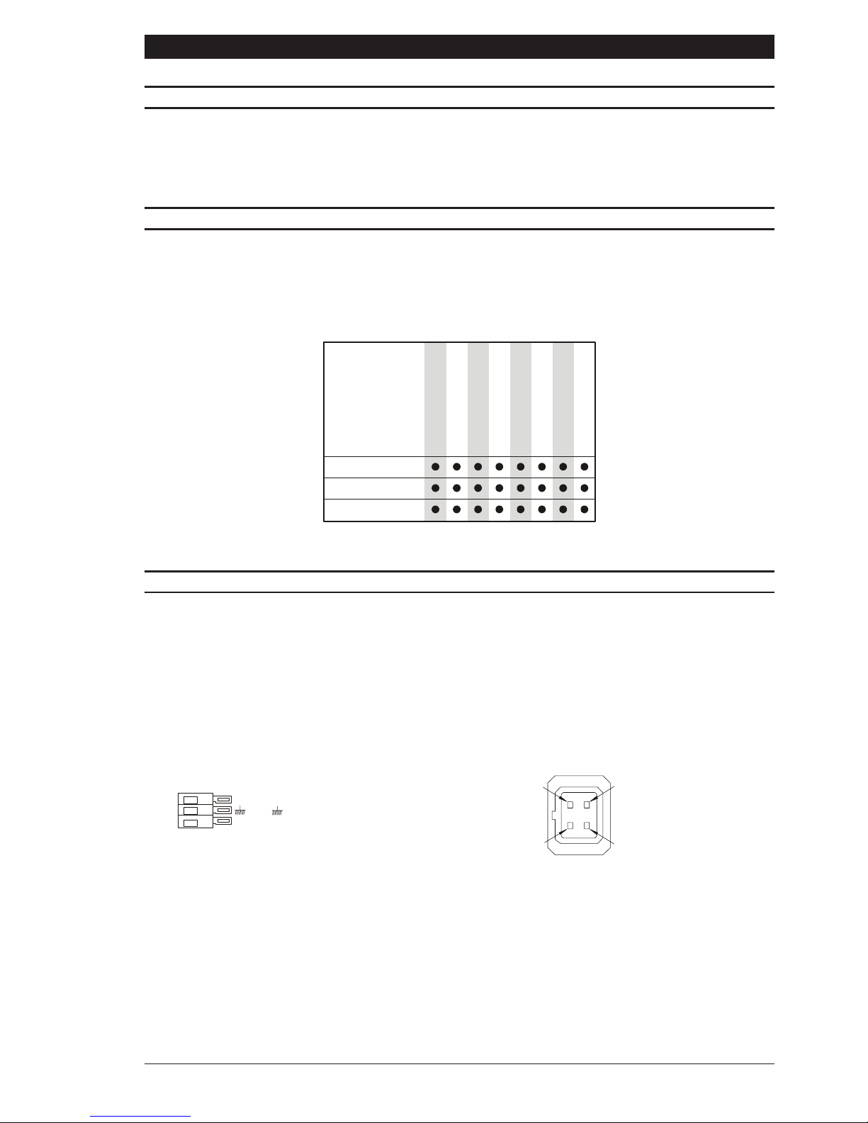
To facilitate backlight compensation, eight pre-defined windows are provided. To select a
window, first, press the BLC window activation switch (see figure 1). This will superimpose
the currently selected window over the video output on the monitor. Use the three dip switches
SW1-4, SW1-5 and SW1-6 to select one of the pre-defined windows according to the diagram
below.
.
SW1
SW2
SW3
1
1
1
2
2
2
3
33
4
44
56
EI ON
EI OF
F
12
SW1
SW2
SW3
1
1
1
2
22
3
3
3
4
44
56
BLC ON
BLC OF
F
13
44444444666666665555555
5
A
FG
H
B
C
D
E
= area used to calculate camera exposure
Page 8
Page 8
X Series DSP Cameras Installation Instructions
FUNCTION SWITCHES
The overlay window will automatically disappear 5 seconds after the last dip switch setting is
made. Any parts of the scene that are not covered by the BLC window will be ignored when
determining the overall scene exposure.
Back Light Compensation feature - Example 1.
People entering a shop through a brightly lit doorway are to be monitored. Without backlight
compensation, a person entering the shop would be seen in silhouette because the relatively
bright background would cause the camera to reduce its exposure.
By using the backlight compensation feature, it is possible to select a window around the area
of interest, i.e. the doorway. Choosing window A, will ensure that the camera exposure
system only uses the central area of the scene to calculate the scene exposure. Therefore a
person entering the shop will be clearly displayed.
Back Light Compensation feature - Example 2.
The camera is required to observe a typical street scene. The sky above the buildings in the
street is very bright causing the cameras exposure system to overcompensate. Using the
backlight compensation feature to select window C ensures that the relative brightness of the
sky in the scene doesnt adversely affect the exposure. The buildings and street will be
correctly exposed.
Flickerless
The Flickerless setting can reduce the flicker caused by certain lighting conditions. Choose
between ON or OFF. The default setting is OFF. Switch SW2-1 must be up. Note that the
Electronic Iris setting must be off for correct operation of the Flickerless function.
Peak White Inversion (PWI)
Excessively bright or peak white areas in a scene can cause auto-iris lenses (Direct Drive and
Video Drive types) to react and close down thereby losing the detail in darker areas of the
scene. The Peak White Inversion feature is designed to overcome this. It allows you to render
any part of the scene over a certain brightness threshold as black.
A typical usage of this may occur in a highway surveillance role. Car headlamps would
normally cause an auto-iris lens to close. By using peak white inversion to render the headlamps
as black, the lens will not react to them and therefore correctly expose the rest of the scene.
SW1
SW2
SW3
1
1
1
2
22
3
33
4
4
4
56
FLICKERLESS ON
FLICKERLESS OF
F
14
SW1
SW2
SW3
1
11
2
22
3
33
4
4
4
56
PKW ON
PKW OF
F
4
Page 9
Page 9
Installation Instructions X Series DSP Cameras
FUNCTION SWITCHES
Select PWI ON or OFF using dip switch SW3-4. The Peak White Inversion threshold potentiometer
(see figure 1), allows you to set the level above which all video is set to black. The default
setting for the camera is PWI OFF.
LENS SELECTION
Suitable lens types are C and CS mount in fixed iris, manual iris, auto iris or direct drive versions.
Sizes are shown below. Cameras are factory set for CS mount lenses. If using a C mount lens,
rotate either of the back focus screws approximately 30 turns anticlockwise before fitting the
lens.
Lens siz e
1/2"
2/3"
1"
CDX9742/LVCDX9742CDX9714CDX9714/LVCDX9772CDX9772/WFCDX9772/LVCDX9772/LV/W
F
LENS CONNECTION
Fixed and Manual iris lenses (for indoor use only) require no wiring connections.
Auto Iris Lenses
Connections for auto-iris lenses are located on the rear of the camera. Connect auto-iris lenses
to the 3 terminal connector according to the diagram below.
Direct Drive
Connect DD lenses to the female 4 pin socket on the side of the camera. If the lens does not
have a DD plug fitted then wire the lens to a suitable plug in accordance with the diagram below.
1 = Damp
-
2 = Damp
+
3 = Drive
+
4 = Drive
-
1
3
2
4
+
V
= Lens positive supply
= Lens ground
= Video drive signal
+
V
DD Lens ConnectorAuto-Iris Lens Connections
Page 10

Page 10
X Series DSP Cameras Installation Instructions
LENS SETUP PROCEDURES
For manual or fixed iris lenses set the EI switch and AGC switch to ON.
Auto Iris lenses
Switch the EI and AGC off. Refer to the lens instructions and adjust the lens for the optimum
picture (video output level of 1V peak-to-peak). Switch the AGC on.
Direct Drive lenses
Where fitted, switch the EI and AGC off. Use an appropriate screwdriver to turn the lens level
potentiometer (under the hinged flap) fully clockwise. Next, slowly adjust the potentiometer
anticlockwise until the optimum picture is obtained (video output level of 1V peak-to-peak).
Switch the AGC on.
FOCUS ADJUSTMENT
The back focus adjustment screws are located on the top and side of the case and should be
adjusted using an appropriate screwdriver. If possible, always use the top screw to adjust the
back focus mechanism.
Turn the adjuster screw clockwise or anticlockwise to obtain focus. When the focus is sharp,
turn the back focus adjustment screw 2 or 3 turns anticlockwise. The picture will lose sharpness.
Turn the back focus screw clockwise until focus is once again obtained. If you have turned the
back focus screw clockwise past the point of best focus, repeat the procedure. The last turn
of the back focus adjustment screw must always be in a clockwise direction. Do not
over turn the back focus mechanism.
Fixed Lenses
Set the lens focus to infinity and view an image greater than two metres away. Focus the image
using the back focus screw. Set the lens focus as required.
Manual Iris Lenses
Open the iris fully and set the lens focus to infinity. View an image greater than two metres
away. Focus the image using the back focus screw. Set the lens focus and iris as required.
Auto-iris and Direct Drive Lenses
Fully open the iris by covering the lens with a suitable neutral density (ND) filter. Set the lens
focus to infinity. View an image greater than two metres away. Focus the image using the back
focus screw. Remove the ND filter and set the lens focus as required.
Zoom Lenses
Set the lens focus to infinity and fully open the iris by covering the lens with a suitable neutral
density (ND) filter. Zoom out to the widest field of vision and view a distant object. Adjust the
back focus screw until the object is in focus. Next, zoom fully in and adjust the lenses focus
until the object is again focused. Repeat these steps until the full zoom range may be viewed
with the minimum loss of focus.
SYNCHRONISATION
Cameras that operate from AC supplies are line-locked for a supply frequency of 50Hz. If the
supply frequency is unstable, then disable the line lock by setting the SYNC switch to Internal.
Page 11
Page 11
Installation Instructions X Series DSP Cameras
65.5122.5
59
.5
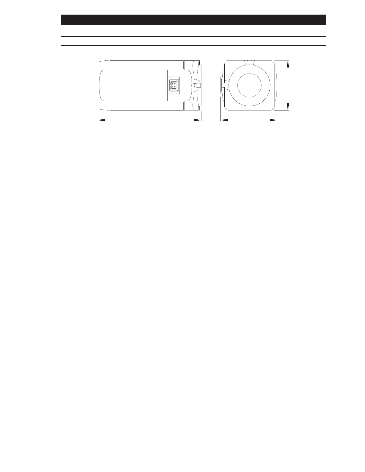
DIMENSIONS
Page 12

Baxall Limited
Horsfield Way, Bredbury Park Industrial Estate, Stockport, Cheshire SK6 2SU
Baxall Limited reserve the right to make changes to the product and
specification of the product from time to time without prior notice
Issue 2 : 5/00 HB-CDX-2
 Loading...