

Page 1

BEDIENUNGSANLEITUNG
INSTRUCTIONS
3X / 3SX
Page 2

QUICK INTRODUCTION
Installation page 4
Preparing the remote control page 5
Connection page 5
LED display page 6
Setup / Einstellung page 7
Flying in page 8
RealTime-Tuning page 8
Tail gyro optimisation page 9
Head gyro optimization page 10
Trimming page 10
APPENDIX
Troubleshooting page 15
Precautions, disclaimer, warranty page 16
Accessories page 17
Service and inquiries, imprint page 18
Setting up the Horizontal stabilization page 11
Tandem-Mixer page 13
ADVANCE INFORMATION
Features, technical data, scope of delivery page 3
SPECIFIC FEATURES OF THE 3SX
2
CONTENT
Page 3

3
FEATURES
Congratulations to now owning a bavarianDEMON stabilization system. In combination with these FBL systems, huge performance is supplied to your model. The head
gyro eliminates all undesired rigid head characteristics, resulting in optimum control and precision. By means of the latest generation high-quality MEMS gyros, these
systems offer full 3D capability, whilst boasting a top-quality, ultra-fast tail gyro. In addition, it has a built-in symmetrical torque control (revo). This results in a further increase
in lock-in ability, made possible by coupling the tail gyro internally with the coll.pitch data of the rotor head control.
The 3SX additionally includes an optional horizontal stabilization (active self-leveling and unique rescue modes), which can also be used in helicopters with fl ybar.
Plus the 3SX features an additional mixer type for the control of tandem helicopters. For more info please see “Specifi c features of the 3SX”.
The 3X expressly incorporates no horizontal or position stabilisation and is thus fully suitable for competition!
Besides this, there is no difference in performance compared to the 3SX, plus it can be upgraded at any time to the full functionality of the 3SX. For further information
regarding upgrade possibilities please see www.bavarianDEMON.com.
Of course, the system is also perfectly suitable for fl ybarless scale helicopters (twin- and multi-bladed) as well as fl ybarless helicopters such as turbine powered trainers,
etc.. And it can be used without limits for all different power types, no matter if electric, nitro or combustion engines, as well as turbines too.
Supported servo types: All current analog, digital and brushless servos, including narrow-pulse servos (760µs) on the tail. Moreover all current swashplate variants,
including four swashplate servos and virtual swash rotation, CCPM/H1, H3-90°, H3-120°, H3-140°, H4-90°, H4-90°+45°.
Direct USB connection for fast programming as well as clear separation of the gain (sensitivity) settings for head and tail gyro in independent auxiliary channels reduce
the setup work to a minimum. In case of the 3SX, the head gyro channel additionally provides activation and in-fl ight-adjustment of the multiple Horizon and rescue
modes.
3X and 3SX can be updated via internet. For hints and instructions, please see PC software.
TECHNICAL SPECIFICATIONS:
Dimensions: 36 x 34 x 14mm
Supply voltage: 4…10V (2S-LiPo-compatible, min. 5.5V using Spektrum/JR satellites)
Max. roll & pitch rotational speed: 500°/s
Max. tail rotational speed: 650°/s (typical)
Tail servo output: optionally digital (220Hz) / analog (55Hz) / 760µs
Head servo output: optionally digital servo (110Hz) / analog servo (55Hz)
Maximum servo currents: Total 10A continuous load, 12A temporary load
Weight: Approx. 18g (without cable loom)
Length of connecting cables to receiver: 90mm (longer cables optionally available, see “accessories”)
SCOPE OF DELIVERY:
• Main unit including assembly material
• Cable loom for receiver connection (90mm)
• USB lead for direct connection to PC/notebook
PC software (Win98, ME, 2000, XP, Vista, 7/8) available for download on www.bavarianDEMON.com.
Page 4
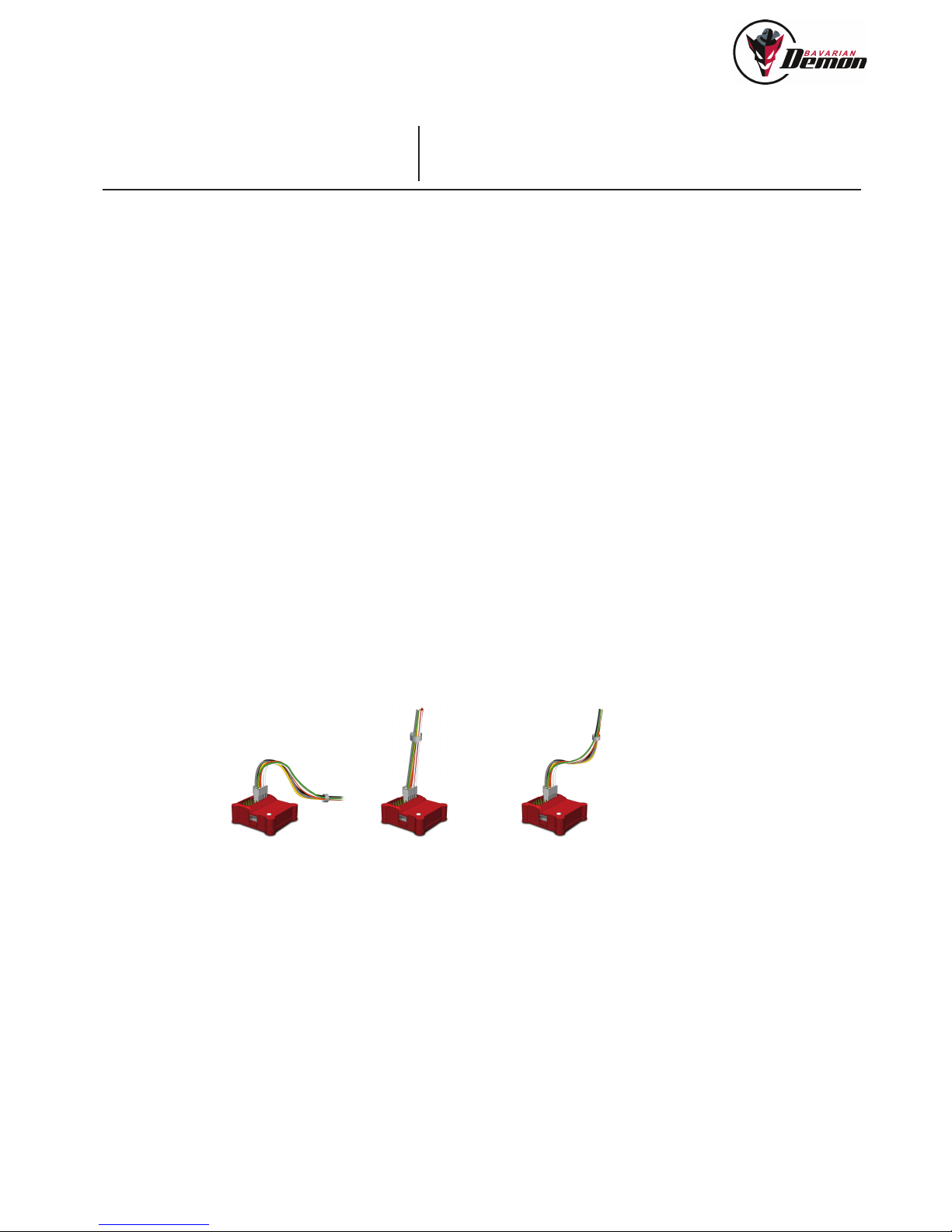
o.k. wrong! o.k.
INSTALLATION
MOUNTING POSITION
Important is an orientation exactly aligned to the level of the main rotor or rotor shaft in all 3 axis, i.e. the assembly surface must be orthogonal or parallel to these.
Contrary to normal tail gyros, this is particularly important to ensure that the head stabilisation maintains constant attitude even during pirouettes. All four main orientation
directions are possible (see PC software), plus mounting it inverted or even vertical.
AVOIDING VIBRATIONS
The mounting surface must be sturdy and vibrate to the least possible extent. The closer it is fi tted to the rotor shaft, the less usually are vibrations.
In case of combustion engines, it is particularly important to optimally observe this issue because of invisible vibrations. If the housing should tangibly or visibly vibrate
extremely while the engine is running, we recommend choosing a different installation position that is protected better against vibrations.
AVOID HEAT
Keep distance from exhaust tube, ESC and motor. Using the system inside a fuselage, make sure to supply fresh air.
USE THE SUPPLIED ADHESIVE FOAM TAPE
Clean the mounting surface properly. Use the thick and softer tape for combustion engines only, the thin tape for all other models.
Do not additionally lash the housing as this would restrict the damping effect of the foam tape. For the same reason, do not tightly lash the connecting cables (servos and
receiver) and do not lay them in a straight line, but in a bend leading to the system.
PREPARING THE REMOTE CONTROL
Switch off ALL mixers in the transmitter. The mixers are set only in the system according to the linkage type. In the transmitter, select an unmixed standard program
(CCPM/H1, in case disable the collective tail mixing). The functions like gyro menu, AVCS menu and pitch-throttle curve remain in the transmitter. Moreover, Expo and
DualRate settings are allowed to be used in the transmitter, but only after the initial setup was completed.
4
QUICK INTRODUCTION
Page 5
CONNECTION
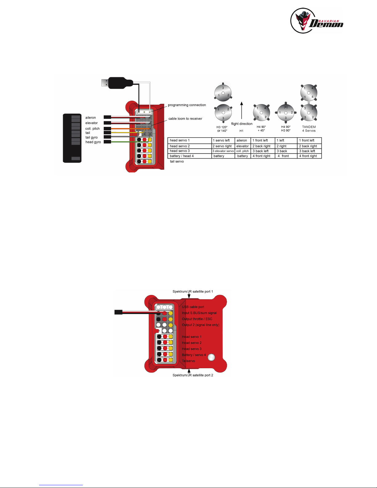
VIA SERVO OUTPUTS (STANDARD RECEIVER)
VIA FUTABA S.BUS OR SUM SIGNAL (ROBBE, JETI, GRAUPNER, HITEC, ETC.)
If the receiver features a sum signal (PPM pulse or ‚serial PWM‘) output, it can be connected via this output, so only one patch cable is needed. Activating this feature is
done via PC software. In this case, the throttle channel is looped through by the system, its output supplied at the neighboring slot named “Output throttle / ESC”.
A further channel is available, Output2, e.g. for speed controller gain, illumination accessories or retractable gear. This channel supplies only the signal pin. The power
needs to be supplied via a Y-cable from e.g. one of the servo ports.
5
Sum.-/PWM-Signal
VIA SATELLITE RECEIVERS (SPEKTRUM / JR)
Up to 2 (diversity) receivers can be connected, one at each side of the system. See the info texts in the PC software for activation, adjustments and satellite binding. No
main receiver is needed for binding the satellites to the transmitter. The usual input ports for tail gyro and head gyro channel must be idle, i.e. not connected to any signal
source. When using Spektrum/JR satellites, the system needs to be supplied with min. 5,5V. 4,8V batteries (4x NiMH or NC) are not suffi cient, the receivers may fail
under load or not bind at all.
Page 6

PLEASE NOTE WHEN CONNECTING
As high servo currents can occur, a voltage supply should be routed directly to the device, also in case of a master-slave supply.
So the receiver will be supplied via the system, not vice versa.
When using the supplied cable loom and an ESC’s BEC is connected to the receiver anyway, the power supply via cable loom is suffi cient. In this case any slave supply
should be routed also to the receiver.
Use one of the following possibilities:
a) Battery connection / head 4 (in case no 4th head servo is used).
b) Programming connection (Note: using a Y-lead for easy handling, so the USB cable can be connected without unplugging the power cable).
c) Any servo port by using a Y cable.
• Do not connect servos until the system has been set to the correct servo type via PC software.
• Do not move the heli/system for the fi rst fi ve seconds after switching on (LED fl ashes red). The system runs a self-test and needs standstill to perform this, as otherwise
it does not activate the servos and starts to fl ash 3x red.
• In case using the cable loom: The cables loom should all be laid as one common bundle. Single wires must not lie separately.
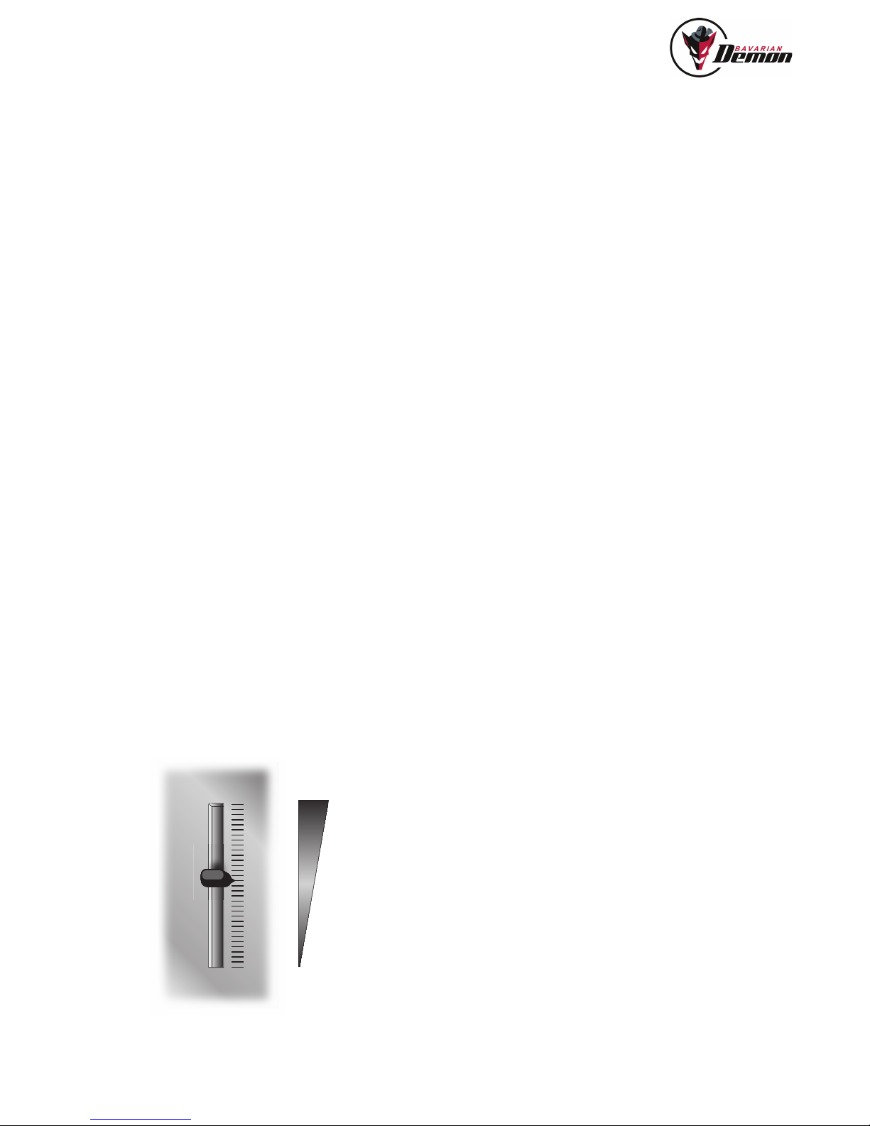
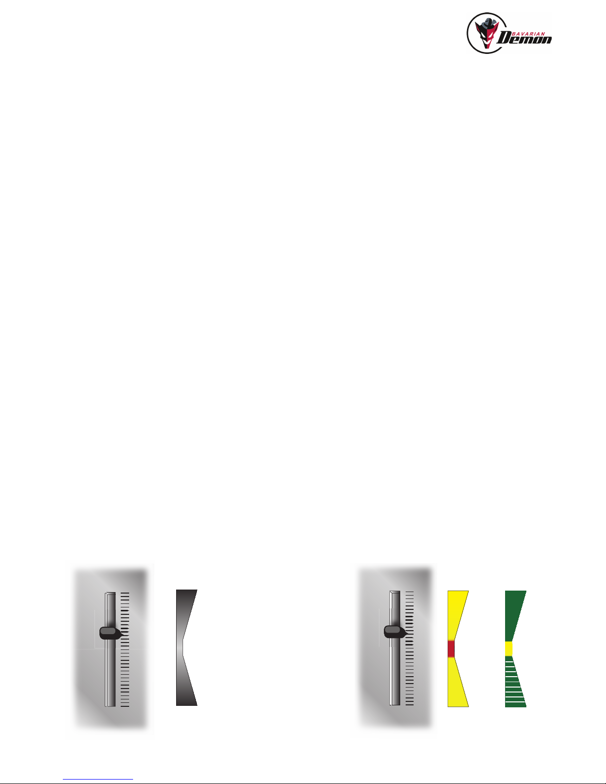
• The additional „head gyro“ and „tail gyro“ channels serve to set the respective gain (sensitivity) in fl ight. One potentiometer or slider on the transmitter each should
be assigned. As an alternative, and recommended for later on, a fi xed value can be programmed on the transmitter, a gyro menu can be used, or the values can be
programmed from the PC directly into the device if the corresponding channel does not see a transmitter input. However, it is considerably easier and faster to have
a pot or slider at the transmitter to adjust directly in fl ight.
LED DISPLAY
SWITCHING ON
(fl ashes red) Switch-on phase: do not move, no output of servo signals
OPERATION
(continuous red) Center of head gyro channel, minimum stabilisation (20%)
(continuous yellow-orange) Active rigid stabilisation > 20%
(continuous green) 3SX only: Horizontal stabilisation ON
(fl ickering green) 3SX only: Horizontal stabilisation with collective pitch rescue action ON
SETTING UP
(fl ickering red) If connected to [Diagnose] or [Trim] menu: Servos remain in neutral position
6
ERRORS DURING SELF-TEST, NO SERVO SIGNAL OUTPUT
(1x) Waiting for RC signal
(2x) Battery as from switch-on < 4V
(3x) Movement during switch-on phase, repeat power-on
(4x) Hor-Mode deactivated cause tilt >30° detected prior to start (only with 3D horizon modes)
(6x) 3SX only: too extreme temperature (>55°C/131°F or <-15°C/5°F)
Page 7

SETUP / ADJUSTMENT
After installation, the system must be tuned to heli and transmitter, which fi rst includes adaptation of the transmitter to the system, followed by setting up the system to the
model. The PC software includes a setup wizard at the bottom screen, guiding you swiftly and easily through all the required steps without missing anything. Additionally
there are helpful mouse-over hints available for each parameter in the software, as well as additional notes in the [Help] menu.
At this point please open the software and start the setup wizard.
And prior to this, do not miss to read the following notes 1-3!
1. IMPORTANT NOTE IN CASE OF USE WITH TURBINE HELICOPTERS!
Only for systems with serial number < 70-x-x (Delivery prior to December 2013):
If running a turbine, it is mandatory to apply the protective hood, available as accessory, protecting the unit from the infl uence of ultrasonic sound. Newer
system are not affected, as their sensors are resistant to ultra-acoustic noise.
2. IMPORTANT BEFORE FIRST FLIGHT AND AFTER ANY CHANGES!
EXTENDED CONTROL TEST INCLUDING A DIRECTION TEST FOR ALL THREE GYRO DIRECTIONS
a) When the model is ready to fl y, check the neutral positions and directions of all stick functions and for all servos. If the swashplate shows an increasing tilt while
increasing the head gyro gain, this must be related to wrong transmitter neutral trim (step 4, b in particular).
b) Check directions of all three sensor axes, as a wrong direction would fairly lead to a crash. Briefl y move the model to and fro about all three axes, tilting and turning.
Swashplate and tail must initially respond with the opposite action, i.e. swashplate wants to stay horizontal against rolling and tilting, and front side of the tail rotor
blades move opposite to the tail swivel direction, i.e. tail rotor blows in the direction of its swivel movement. In the event of errors, a mistake must be either in the
direction of the bars in the [Diagnose] menu or in the ‚mounting orientation‘ setting.
c) RC range test.
3. [ALL] MENU: BACKUP OF ALL SETTINGS IN THE PC
Data backup is optional, since all settings are stored permanently in the device, unless they are overwritten by new values or a factory reset. It also makes sense to
save settings when carrying out tests with various parameters. If the result is not satisfying, you can easily restore the prior data by loading the backup.
7
Page 8
200%
100%
0%
+ 110% (JR)
-90 (Futaba)
0%
1,5 ms
-110 % (JR)
+90 (Futaba)
8
FLYING IN
! It is mandatory to have tested all sensor directions! (page 7, point 2)
! First fl y with considerably reduced gain settings for tail and head gyro (40% recommended).
! Control test before every take off. Never take off before the servos can be moved. Only if servos are moving, the initialisation was successfull.
PAY ATTENTION DURING TAKEOFF
! Generally pay attention to the horizontal position of the swashplate.
Similarly to a tail gyro, it may happen that inadvertently issued slight stick defl ections are amplifi ed by the stabilisation before you are in the air.
! Especially 3D-acro helis with a hard head-damping must not be launched on hard asphalt, unless skids are dampened. Otherwise, when the motor is spooled up,
resonances can occur with the risk of tilting over the heli, because in this state it cannot correctly follow the system‘s control commands.
REALTIME-TUNING
The channel that normally controls the tail gyro gain can be assigned for control of any parameter from [Tail gyro] and [Rigid] menu (and [Horizon] menu in case of 3SX).
Note: When using this option, make sure, that the previously found tail gyro gain is set fi x in the [Tail gyro] menu (see PC software).
When you have selected and assigned a parameter in the [RealTime-Tuning] menu, you can adjust it in fl ight from the transmitter via the ‚modifi ed‘ gyro channel. It is best
to use a slider or a potentiometer on the transmitter (or a fi xed value programmed there).
The applicable parameter‘s setting can be altered from zero to twice the pre-set value (active value is shown in the RTT tab), but no higher than the setting limits. Neutral
signal from the transmitter results in the parameter value as set in the PC software (Factor 1.0).
When the assignment is cancelled again, the setting made on the transmitter is discarded, i.e. it will not be saved automatically. You have to set it manually as the new
setting for this parameter.
REALTIME-TUNING CHANNEL
Page 9
+ 110% (JR)
-90 (Futaba)
0%
1,5 ms
-110 % (JR)
+90 (Futaba)
100%
RIGID
20%
gain
RIGID
100%
100%
HOR ON
0%
HOR OFF
100%
HOR +
C.pitch Act.
ON
100%
Heading
Hold
10%
gain
Normal
100%
RIGID-MODE HOR-MODE
TAIL GYRO OPTIMISATION
SENSITIVITY (GAIN) SETTING
As usual, set the gyro gain as high as possible, at which the tail does not yet tend to oscillate, not even at high fl ight speed. The tendency to oscillate and thus the holding
force crucially depend on the speed of the tail servo, but also on a play-free and easy-moving linkage as well as an optimum drive (no belt slipping, no breakdown of the
motor controller at full coll.pitch, etc.).
You can additionally optimise the gyro‘s performance to the model by tuning further parameters of the [Tail gyro] menu. In the case of high-performance acro helicopters,
the following tuning procedure has proven itself and excellent performance can be achieved with it, even under extreme loads.
P-GAIN
Search for the setting at which the tendency to oscillate is at its lowest (referred to the same overall tail gain),
and you may then further increase the overall gain to some extent.
• You prevent fast oscillations (fi ne dithering) by a lower overall tail gain.
• You prevent slow oscillations and bouncing back by a higher P-gain.
DELAY
Use this to optimise the locking-in when the stick is released suddenly, with the result that the tail stands still without bouncing back or overshoot. Before adjusting the
delay, adjust the tail gyro gain to a good and high value.
REVO-MIX
To improve tail stability (particularly with slower tail servos) by generating a direct ahead correction for the tail with every load change caused by coll.pitch elevations, even
before measurable drift occurs, which the gyro would have to fi rst detect in order to balance it out.
For the Revo-mix you can select:
• for 3D-fl ying → symmetrical pitch curve
• For scale fl ying, with coll.pitch hover position in stick centre → asymmetrical pitch curve
Optimise Revo mix with reduced gyro sensitivity as a test measure: Issue sharp coll.pitch defl ections and observe the tail. If the
tail gives in to the torque at the start of ascent, i.e. swivels in the opposite direction to the main rotor, then increase the Revo amount. Finally raise the gyro sensitivity
again.
OPTIMISING THE ESC
If the tail performs a tiny excursion only after a coll.pitch change, the cause of this is mostly a sluggishly responding motor controller that allows the motor speed to break
down briefl y at the maximum load and then accelerates, thus applying a high load to the tail. In this case, mostly an improvement is achieved by increasing the motor‘s
speed.
TAIL GYRO CHANNEL HEAD GYRO CHANNEL
9
Page 10

10
HEAD GYRO OPTIMIZATION
The attitude stabilisation („head gyro“) for the rigid linkage maintains any pilot-operated attitude and prevents disturbances, like e.g. ballooning. On ground, the function
is visible at the swashplate: when giving control commands and let go off the stick, the swash moves slowly back to level, maybe even stays in the inclined position for a
short while.
AN EFFICIENT WAY TO OPTIMISE THE RIGID SETTINGS:
• We suggest to use a pot or slider at the radio to easily fi nd the optimum gain. Use the ‚Head-gyro‘ channel or, in case no signal is supplied from the transmitter, it‘s
default gain slider in the [Rigid] menu to set the gain as high as possible, approx 10% below the onset of oscillations. For safety reasons, begin with small values. Too
high gain may provoke oscillations, for example like a ‚shivering‘ in roll axis or a pitching in elevator axis.
• Then set the ‚agility‘ slider in the PC software as desired. Only with 3Xbase, use the transmitter‘s travel settings.
• Usually at this point the performance is close to the optimum or perfect. If improvement is necessary,
you can test sudden halt (‚locking-in”) after vigorous and abruptly ended stick defl ections:
In case of a tendency of rocking / luffi ng in elevator axis, increase the elevator fi lter value (see the tool-tip). This job is easily done by using RealTime-Tuning, after having
pre-set the elevator fi lter to a medium value.
In case of abrupt and jerky reaction to small and sudden stick inputs: Reduce ‚Initial response‘, or increase ‚Rigid gain’ or ’P-portion’.
In case the turning continues a short while even after ending the stick defl ection:
- for avoiding a too soft (sluggish) reaction: Increase ‚‘Initial response‘; possibly also increase the ‚Rigid gain’ and/or the travels in the [Mixer] menu.
- for avoiding exaggerated and harsh reactions: reduce ‚Agility‘ in the [Rigid] menu, and carefully increase the travels in the [Mixer] tab.
If aileron and elevator impulses cause mixed movements, this might be because of an incorrect setting of „virtual swashplate rotation“. Test it with reduced rigid gain: If the
tail moves downwards in the event of rolling to the right, then increase swashplate rotation in the positive direction.
• Test response to long stick elevations:
- In the case of a strong fi rst reaction and then decelerated continued reaction: reduce ‚Initial response and, if applicable, increase the „Agility“.
• Test high-speed fl ight
- Against slow ballooning or undercutting: reduce or resp. increase the „withdraw rate“.
- Against temporary nose-up („dolphin“) during harsh coll.pitch rises: increase ‚Rigid gain‘ as far as possible.
Also try with increased P-portion and ensure mixer is set to maximum travels.
- Against lasting ballooning after hard coll.pitch-up: see mouse over text for „altitude holding range“.
• In case of tilting or tumbling motion during pirouettes:
Align the sensor parallel to the rotor shaft.
Trim the swashplate exactly straight while there is a connection to the [Trim] menu (necessary to have all servos at neutral).
TRIMMING NEUTRAL
Using Rigid stabilisation, trim adjustment at the transmitter is not allowed (and not necessary) any more. The system would interpret this as a control input.
Helicopters equipped with fl ybar, even though they would not need a Rigid stabilisation, can still use this stabilisation in order to correct any minor trim differences
and drifts. To do so, use the preset button [Flybar: stab] in the [Rigid] menu.
If necessary, the setting can be optimised using the gain (by RC or default setting) and the ‘Direct control portion’ slider. ‘Elevator fi lter’ may be used as additional
feature.
Page 11

As long as the functions of the [Horizon] menu are not activated, the 3SX’s function is identical to the 3X’s function.
SETTING UP THE HORIZONTAL STABILIZATION
Important: The 3SX does not allow „exceptions“ during the setup procedure of Horizon and Rescue modes, in particular:
• The coll.pitch travel must reach its 100% marks as displayed in the [Diagnose] menu, positive and negative, with the correct direction.
• For using any of the extended 3D options, the angle of attack has to be exactly 0° when connected to the [Diagnose] or [Trim] menu. Otherwise a proper function of the
3SX’s horizon and rescue features can not be ensured.
The horizontal stabilisation can be used for various purposes, primarily as training aid (“safety net”) for beginner as well as advanced pilots, from the fi rst steps up to trai-
ning new maneuvers, using the stabilisation only as a „rescue switch“ in an emergency case or permanent horizon activation (“Coax mode”).Moreover, a support during
photographic fl ights, particularly in greater distances is a possible application.
HOW TO ACTIVATE THE HORIZONTAL STABILISER
Using a helicopter without fl ybar, fi rst optimise the Rigid/head gain setting. We suggest to use a switch or better a pot or slider on the transmitter for instant adjustment ac-
cess. Then read the resulting gain-setting of the head-gyro channel from the [Diagnose] menu (not from the transmitter, values may differ!) and enter this value as default
setting into the [Rigid] menu and write to the system.
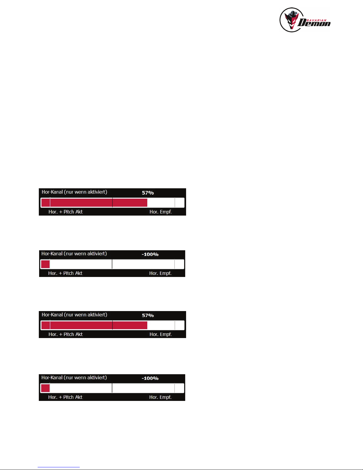
To activate Horizon mode, use the [Horizon] menu to switch the channel assignment from ‚Rigid gain‘ to ‚Horizon‘. Using the head-gyro channel, you can now control the
strength (gain) of the Horizon mode during fl ight and switch between modes.
Note: the 3D options act depending on the signal polarity (direction) given at the head-gyro channel.
FLYING WITH HORIZONTAL STABILISATION
Before starting the motor, ensure that the swashplate remains in approximate horizontal position while activating the Hor-stabilisation. It must not run into an end-blocking
(can occur when initialized on the ground for a longer time).
Begin with low stabilisation gain and increase carefully. Rigid stabilisation, set at high level, may increase a tendency to oscillate. Normally, take-off and landing is possible
with activated Hor-Mode. This should be tested fi rst with a gain not higher than 30% fi rst. The tendency to oscillations may be increased before take-off, if the skids are
standing on a hard surface and during fast fl ight.
Important:
If fl ying with permanently engaged Hor. stabilisation, do not reduce travels for aileron or elevator at the transmitter (dual rate). Otherwise, the priority of the manual control
(override), which is necessary for safety reason, may get lost. The Horizon stabilisation can make pirouettes out-of-round, since it aims to bring the main rotor plane into
its neutral hover attitude (adjustable in the [RC] menu): for round pirouettes reduce the Horizontal strength (gain) and/or increase the Rigid stabilisation.
11
PARTICULAR FEATURES OF THE 3SX
Page 12
12
HORIZON MENU
Select the desired mode of operation using the parameter “self-leveling mode”. Beyond that, there are several ‘Advanced’ options available, which are precisely explained
in the tool-tips (mouse-over) and that can usually be kept untouched.
Following you will fi nd all explanation of the different options:
1 [hover & scale] LED green = ON, red/yellow = OFF
Not suitable for 3D fl ying and allowed only for helicopters which, due to their c.pitch range, are not capable of inverted fl ight. The gain channel here works
similar in both directions, no matter if negative or positive signal is supplied, e.g. +50% = -50%.
The 3D modes provide the most reliable „rescue“ functions. These options are allowed only if the model will not be tilted more than 30° from powering on the 3SX until
takeoff. In regards to safety concerns, it is always recommended to „arm“ the heli at the starting point.
2 [acro] LED green = ON, red/yellow = OFF
The most recommended option for 3D fl ying with best accuracy. The model will be self-leveled to the „closer“ horizontal attitude (normal or inverted). The decision wether
the heli will be leveled upright or inverted, is additionally depending on the current c.pitch stick position. As long as inclination was less than ca. 45°, the main attitude will
not change.
Example c.pitch stick dependency: if the heli has an inclination of 70° on elevator and/or aileron, i.g. is closer to normal fl ight attitude than inverted, but the current c.pitch
signal is ‘negative’, then the heli will be leveled inverted. For activation choose [Acro] mode and apply a positive signal to the Horizon (head gyo) channel, defl ection to the
right in between 10-100%. The higher the value, the stronger the stabilization.
2b) [acro with pitch] LED fl ickering green = ON, red/yellow = OFF
Similar to Acro mode, and additionally c.pitch will automatically be controlled and set for climbing (“escape into the sky”). Read tooltips in PC software! For activation
choose [Acro] mode and apply a negative signal of -100% (or higher) to the Horizon (head gyro) channel, i.e. left direction in the [Diagnose] menu.
3) [upright self-level] LED green = ON, red/yellow = OFF
Always levels a 3D heli in upright attitude, even if fl ying fully inverted. For activation choose [Upright self-level] mode and apply a positive signal to the Horizon (head gyo)
channel, defl ection to the right in between 10-100%. The higher the value, the stronger the stabilization.
3b) [upright self-level + pitch] LED fl ickering green = ON, red/yellow = OFF
Similar to Upright self-level mode, and additionally c.pitch will automatically be controlled and set for climbing (“escape into the sky”). For activation choose [Upright self-
level] mode and apply a negative signal of -100% (or higher) to the Horizon (head gyro) channel, i.e. left direction in the [Diagnose] menu.
Page 13

AUTOMATIC COLL. PITCH
The automatic c.pitch action of the rescue features (2b) and (3b) overrides the pilot‘s c.pitch commands more and more with increasing gain setting at the Hor.-Channel. A
signal of -100% (according to [Diagnose] menu) completely overrides the x.pitch stick commands, which is the highly recommended setup. Furthermore, the rescue mode
should be triggered only by a spring loaded momentum switch, so that the pilot re-gains full control by releasing the switch.
NOTE ABOUT THE RESCUE OPTIONS (EXTENDED 3D LEVELING MODES)
The described rescue options provide an extremely high reliability, even during extreme 3D and acro maneuvers, acted in accordance with our rules for setup and hand-
ling. The sensors‘ immunity against vibrations, particularly of the Horizon-stabilisation, is unmatched.
We see this feature as a highly effi cient rescue option, as well as a training chance for un-familiar acro maneuvers.
However we warn to not go for any risks, particularly not to pull the rescue button for testing without fl ying in suffi cient safety altitude, unless being in a real trouble situati-
on. Likewise, nobody would use an emergency-only parachute for regular skydiving. As with any complex system, even in model fl ight, unpredictable infl uences have to
be accounted for at any moment. Also note that the leveling can naturally not perform a halt from high speed, and the heli may climb sideward.
The manufacturer confi rms an extremely high reliability of proper operation, but excludes any liability for damages caused by lack of function (no or wrong or delayed
reaction etc.).
TANDEM MIXER
LINKAGE
The linkage of the two swashplates requires the use of 4 servos, 2 pieces per swashplate. Since elevator is controlled via c.pitch on a tandem, it must be ensured that the
two swash plates can tend only on aileron. The conventional elevator function must be mechanically disabled (blocked). To achieve this, you need a H4 swashplate with
a V-rod, which is led by servo at 2 ball links per side. As the rods are in V-shape, the elevator function on the swashplate is eliminated. This must be given on both sides
of each swashplate. Please take care that the swashplates are 90 ° aligned to the main rotor shaft. Make sure that the rotation of the swashplates is prevented by swash
drivers. Also note that each linkage is smooth-running, only thus ensures that the swashplate working properly and no mechanical load occurs.
Now please carry out the setup by running the software’s setup wizard as usual.
EXTRAS
In the selection menu for the swashplate type, select „Tandem“. The wizard then skips the sections „Tail gyro“ and „Rigid“ because for the fi rst fl ight there is nothing to
adjust here.
Plug in the servos according to the connection diagram, column “Tandem“. Since the tail servo is omitted, this port can be optionally used for power supply.
The neutral trimming is done as usual on the Trim page. When in this page, set the servo arm to 90 ° and mechanically trim both swashplates horizontally. They should
be centered in between dome plate and center part. Only this way the control via elevator and c.pitch can work optimally.
For hover c.pitch set approx. 2-3° angle of attack on the blades of both rotors.
COLLECTIVE TRAVEL
a) In the Mixer page, see the parameter „Tandem: elevator front portion“ (see also tooltip in PC software). With this parameter you can differentiate the c.pitch
travel of the two swashplates for the elevator function, so that you get more or less collective travel at the tail in relation to the front for the elevator function.
In tandem helicopters generally, the front requires less collective portion. If both travels on front and rear are the same, the helicopter behaves dolphin-like
on elevator commands and the front rotor starts „diving“.
For perfect setup, set both rotors to 0° using the collective stick. Now go elevator full travel forward and measure the angle of attack on the rear rotor’s
lades. Now the front attack angle should be ideally half of the rear’s angle. Example: rear 6°, then set the front to 3°. To reduce the front path, move the
parameter to the left in the negative range, to increase it to the right in the positive range. By experience, a value of -30 is mostly suiting best, but can vary
depending on the heli model.
b) Set negative collective to not more than -3°. Inverse fl ight attitude is impossible anyway, due to missing or incorrect tail gyro effect.
13
Page 14

14
AILERON TRAVEL
For optimal response of the tail gyro, it is useful to set maximum possible aileron travel. The more aileron travel in the Mixer page, the more is available for the tail gyro as
the limit for aileron and tail is the same. Due to the high torque produced by a tandem helicopter it requires a lot of travel to control this.
If the helicopter reacts too agile due to the high aileron travel, you can reduce this within the Rigid page using the Agility setting or also with Expo / DualRate setting in the
transmitter.
HEAD GYRO, RIGID PAGE
Attention: If swash type „Tandem“ was selected, the head and tail stabilization is automatically adjusted to a reasonable preselection of values the tandem scale helis.
Therefore do not change the factory settings in the „RIGID“ and „Tail gyro“ pages until the fi rst fl ight.
The non-grayed-out parameters can be used furthermore, but are already optimized in their default to a medium-sized tandem scale heli. The grayed parameters have no
function at a tandem (Elevator fi lter, Revo mix, etc.).
TAIL GYRO
See above. As with the head stabilization, the [Tail gyro] page should be initially kept at standard default values. The non-grayed parameters can be optimized in later
fl ights if necessary.
SENSITIVITIES/GAINS
Set the tail always to 100%, regardless if using heading-hold or normal mode.
Start with a head gain at about 60% and optimize slowly until possibly experiencing the usual oscillating at a too high sensitivity. Then decrease slightly.
FLYING-IN
Tune the tail gyro fi rst in normal mode! If the tail drifts, the two swashplates must be fi rst trimmed mechanically correct. Only then activate the heading hold mode. Other-
wise, the tail stabilization would work asymmetric.
Page 15

TROUBLESHOOTING
SERVOS DO NOT RUN AND LED FLASHES RED
See page 6 (LED)
FINE AGITATION MOVEMENTS AUDIBLE WHEN USING DIGITAL SERVOS
No problem, these result from the control loop, made hearable by modern ultra fast servos.
RHYTMICAL JUMPING ON SERVOS IN SHORTER OR LONGER INTERVALS
Only appearing in static condition like on a desk, integrators unloading, not present in fl ight.
JERKING TAIL SERVO
If the tail gyro‘s auxiliary channel is at neutral position, it will stay around the switching point between heading hold mode and normal mode, and will randomly switch it on
or off. Use either a positive or a negative signal in the tail gyro channel to defi ne heading hold or not and to obtain a useful gyro gain.
STEPWISE SERVO MOVEMENT
No problem - this is the slower time grid (frame rate) in which some RC systems transfer their pulses.
With the faster frame rate of the device, this is merely more clearly visible on the servos.
NO CALM FLYING ATTITUDE ON THE TAIL AND/OR HEAD
Extreme vibrations (visible or tangible only) on the housing (especially in the case of internal combustion engines) → Observe installation notes on page 4. Or non-correct
center signals (check in [Diagnose] page).
TILTING DURING PIROUETTES (LURCHING OR TUMBLING MOTION)
• Housing not mounted exactly aligned to the rotor shaft?
• With a neutral signal (when in the [Diagnose] menu), swashplate not exactly perpendicular to the rotor shaft?
• 3SX only: Horizon stabilisation active? → (neutral attitude, see p.11 bottom)
TILTING DURING PIROUETTES, ONLY DURING STRONG WIND OR IN HIGH SPEED
• Equalize aileron and elevator travel in [Mixer] menu.
• Use similar Rigid gains for aileron and elevator (Rigid Menu).
WEAK TAIL HOLDING
Travel limit and gyro gain correctly set?
High enough rotor speed?
TAIL UNEXPECTEDLY SWINGS OUT TO THE SIDE
Tail drive (belt or shaft) slipping?
Too high attack angle on tail (stall)?
Enough power on the tail (rpm high enough)?
15
APPENDIX
Page 16

16
WE RECOMMEND FOR YOUR SAFETY
• Always observe a suffi cient safety distance from persons and objects.
• Do not underestimate the weightiness of rotating rotor blades.
• Always observe legal regulations.
• Keep your distance from radar stations, transmission masts and other radio interference sources.
• When passing on the model to third parties, always pass on these warning notes as well!
DISCLAIMER
Installation, adjustment and operation of the autopilot and a helicopter require appropriate skills. Errors and lack of attention can result in accidents involving severe
personal injury and/or property damage or even traffi c accidents. As the manufacturer and seller have no infl uence on correct handling, these risks are expressly pointed
out. Liability for all manner of damage resulting from operation, even due to disruptions of the built-in instruments or signal transmission, is fundamentally ruled out, insofar
as legally possible.
WARRANTY
We assume a warranty of 24 months for this device.
Any repairs performed will not extend the warranty period. During the warranty period, we will remedy any occurring malfunctions or manufacturing or material fl aws free
of charge. Further claims, e.g. in the event of consequential damages, will be ruled out. The unit must be transported to us at no expense to us, and it will also be returned
at no expense to us. We cannot accept unpaid consignments. We cannot assume any liability for transportation damage and loss of your consignment. We recommend
appropriate insurance.
THE FOLLOWING PREREQUISITES MUST BE MET FOR PROCESSING OF YOUR WARRANTY CLAIMS:
• Purchase receipt included with the consignment.
• The devices have been operated in compliance with the operating instructions.
• The device has not suffered any moisture damage, unauthorised tampering,
excess voltages, overloads or mechanical damage.
• If possible, include pertinent hints on how to detect the fault.
NOTE
This document contains legally protected information. All rights reserved.
The content of this document can be amended or adapted without prior announcement.
The bavarianDEMON may be modifi ed at any time on the basis of ongoing tests and resulting improvements. Please inform yourself regularly about current versions of
the instructions, bavarianDEMON fi rmware and PC software.
The manufacturer provides no warranty for operability and usefulness in specifi c applications
The manufacturer is not liable for errors in this documentation and resulting damages in connection with equipment, performance
or use of the material.
Page 17

17
Foam tape ‚Acro‘ (3 pcs) No. 92769
Foam tape ‚Soft‘ (3 pcs) No. 92770
Cableloom L90 (90mm) No. 92771
Cableloom L150 (150mm) No. 92772
Cableloom L250 (250mm) No. 92773
USB cable No. 92774
Ultra-acustic suppression hood No. 92775
ACCESSOIRES
Page 18

Hiermit erklärt die CAPTRON Electronic GmbH, dass sich dieses Gerät in Übereinstimmung mit den grundlegenden Anforderungen und anderen relevanten
Vorschriften der entsprechenden CE Richtlinien befi ndet. Die Original-Konformitätserklärung fi nden Sie im Internet unter www.captron.com.
CAPTRON Electronic GmbH hereby declares that this device conforms to the basic requirements and other relevant regulations of corresponding CE directives. The
original Conformity Declaration can be found on the Internet at www.captron.com.
Par la présente, la Sté CAPTRON Electronic GmbH, declare que cet appareil répond aux exigences fondamentales et à d’autres prescriptions signifi catives des
directives CE correspondantes de la Communauté européenne. L’original de la declaration de conformité se trouve dans l’Internet sur le site www.captron.com.
CAPTRON Electronic GmbH, declara que este aparato cumple con las exigencias básicas y otros reglamentos relevantes de la norma CE correpondiente. La
declaración de conformidad original, la puede encontrar en internet en www.captron.com.
Con la presente, la CAPTRON Electronic GmbH dichiara che questo apparecchio è conforme con i requisiti e le altre disposizioni essenziali della direttiva CE
corrispondente. La dichiarazione originale di conformità è disponibile all‘indirizzo www.captron.com.
Firma CAPTRON Electronic GmbH tímto prohlašuje, že tento p ístroj je v souladu se základními požádavky a jinými relevantními p edpisy odpovídajících sm rnic
CE. Originální prohlášení o konformit naléznete v internetu pod adresou www.captron.com.
18
SERVICE AND INQUIRIES
and lists of authorised dealers, e-mail Kontact, etc.: see our webpage www.bavarianDEMON.com
IMPRINT
CAPTRON Electronic GmbH
Johann-G.-Gutenberg Str. 7
D-82140 Olching
Germany
Fon +49 8142 4488 -0
Fax +49 8142 4488 -100
VERSION 6.1
D
GB
F
E
I
CSZ
 Loading...