

Page 1

Reference manual
DinBox PSTN (485)
modem
Page 2
DinBox PSTN Reference manual – V1.3
Bausch Datacom NV
2
! CAUTION !
ELECTRIC SHOCK HAZARD IF COVER REMOVED
SERVICE BY QUALIFIED PERSONEL ONLY
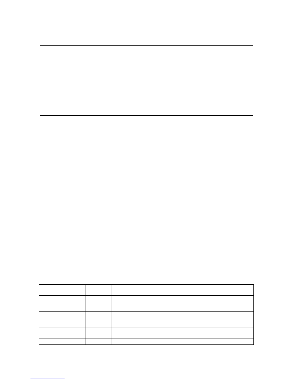
Document History
Date Version Status Author Info
21/10/2004 V1.0 Preliminary Filip Lavaerts Creation
22/02/2005 V1.1 Filip Lavaerts DinBox PSTN(485) ? RS -485 option
18/03/2005 V1.2 Filip Lavaerts Selective CID answer function (8. 2.4)
PSTN line connection (4.3)
08/02/2006 V1.3 Filip Lavaerts Approval info
Jumper JP2 / RS -485 example / RS-232 connections
Page 3

DinBox PSTN Reference manual – V1.3
Bausch Datacom NV
3
Page 4
DinBox PSTN Reference manual – V1.3
Bausch Datacom NV
4
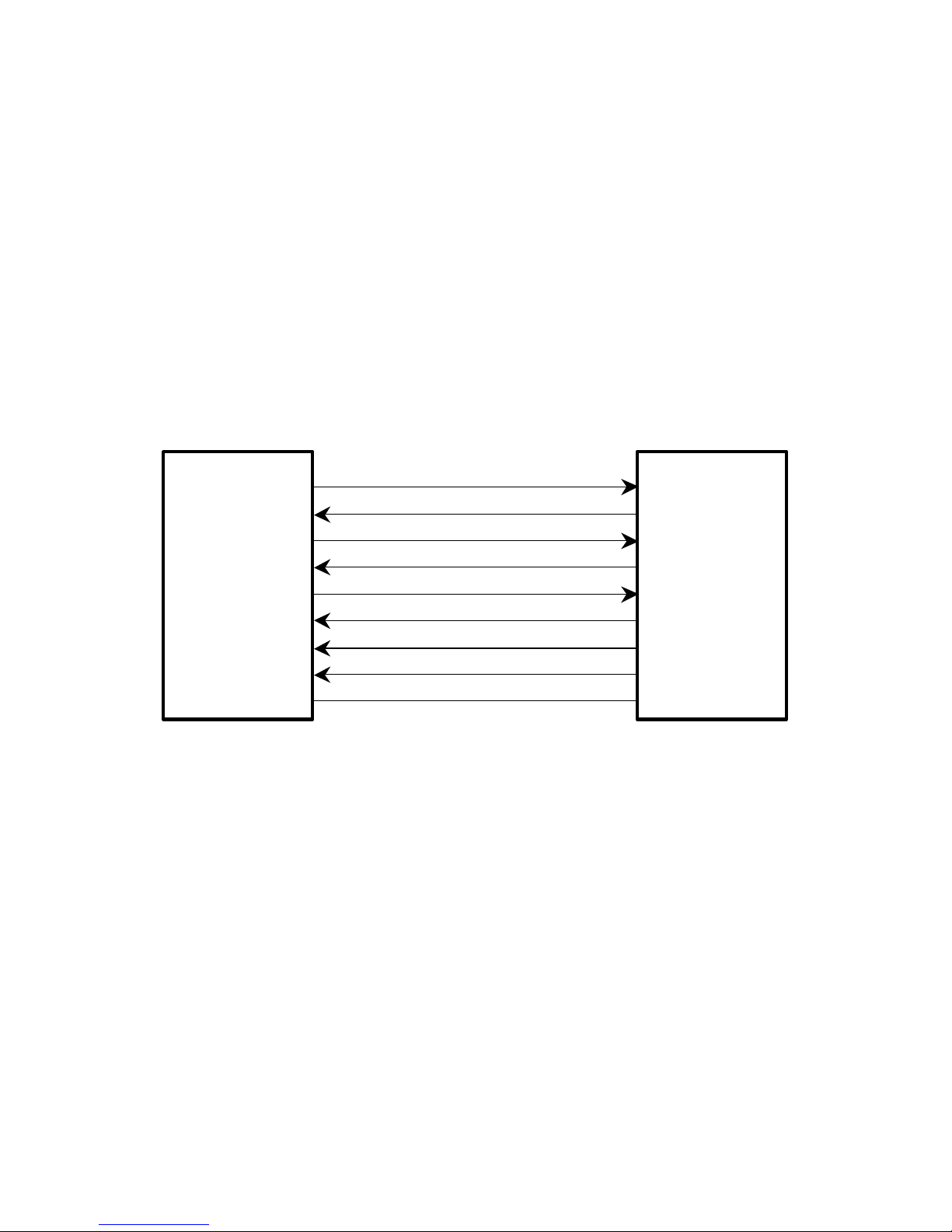
Serial signal flow definition in this manual
DCE
DTE
TxD
RxD
DTR
DCD
RTS
CTS
RI
DSR
GND
Modem
DinBox PSTN
. . .
Communication
device
PC
POS
PLC
. . .
Application
IN OUT
Data
Terminal
Equipment
Data
Communication
Equipment
Page 5

DinBox PSTN Reference manual – V1.3
Bausch Datacom NV
5
1. Introduction 6
2. Block Diagram 7
3. Specifications 8
3.1 Housing 8
3.2 Connectors 9
3.3 Environmental conditions 9
3.4 Power Supply specifications 9
3.5 PSTN modem specifications 10
4. Ports and Connectors 11
4.1 Power connection 11
4.2 Standard DTE Interface 12
4.3 PSTN connection 12
5. LED Indicators 13
6. Watchdog functionality 13
7. RS-485 interface 14
7.1 External connections 14
7.2 Schematic overview of the RS-485 circuit 15
7.3 Possible jumper settings 16
7.4 Example configuration for RS-485 communication 17
8. AT-commands interface 18
8.1 Standard command overview 18
8.2 Enhanced features 22
8.2.1 Dump mode 22
8.2.2 Leased line configuration 22
8.2.3 Asynchronous DTR-dailling 23
8.2.4 Selective CID answer 23
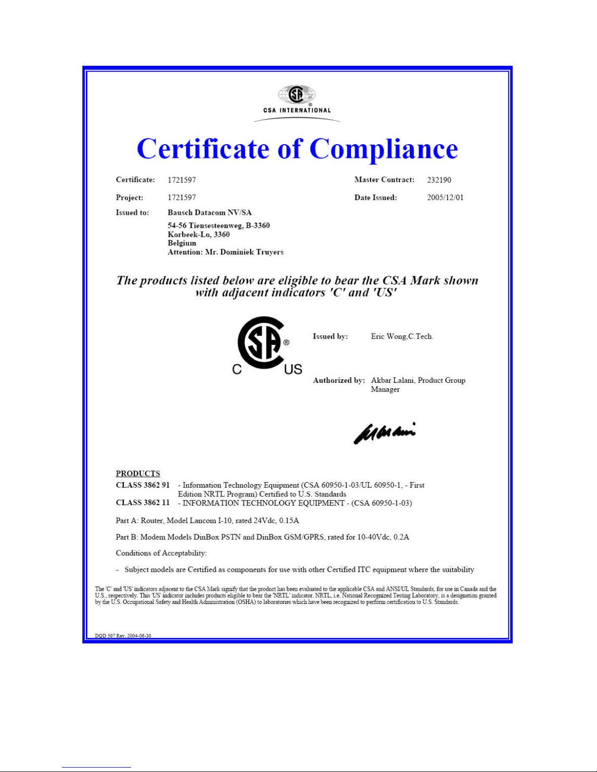
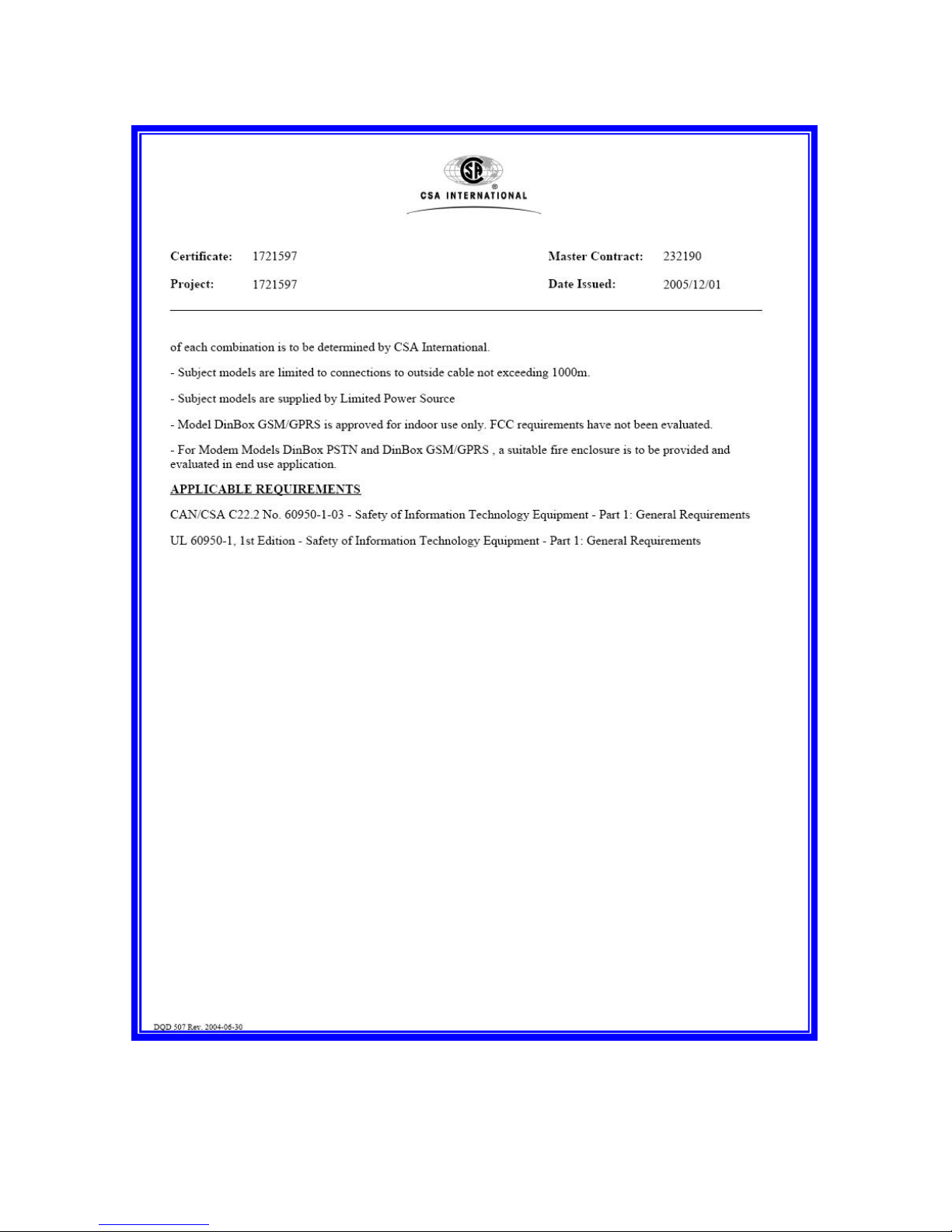
A. Certificate of compliance c-CSA-us 24
B. EC-declaration of conformity 26
Page 6

DinBox PSTN Reference manual – V1.3
Bausch Datacom NV
6
1. Introduction
This manual is the reference book when setting up the DinBox PSTN(485) modem for
your application. Because of the nature of this product and it's field of application, some
degree of technical background knowledge regarding the application and datacommunication is assumed.
The DinBox PSTN(485) modem is a versatile communications device designed to
provide a very flexible data communication solution for an industrial environment.
To ensure problem free communication, the DinBox PSTN(485) is equipped with a ‘long
term’-watchdog. This circuit will ‘hard’ reset the modem every 24 hour.
The DinBox PSTN(485) is designed to transmit and receive data on the Public
Switched Telephone Network - PSTN.
The DinBox PSTN(485) has a lot of enhanced communication features implemented :
- error correction / data compression
- Caller ID detect
- V.22bis fast connect
- 2-wire analogue leased line
- dump mode
- asynchronous DTR dialing
The DinBox PSTN(485) is designed in a robust 22.5 mm wide DIN rail housing with a
wide range DC- power supply.
The DinBox PSTN(485) version has an internal RS-485 2-wire and 4-wire interface.
See chapter 7 for more details about this interface.
Page 7
DinBox PSTN Reference manual – V1.3
Bausch Datacom NV
7
2. Block Diagram
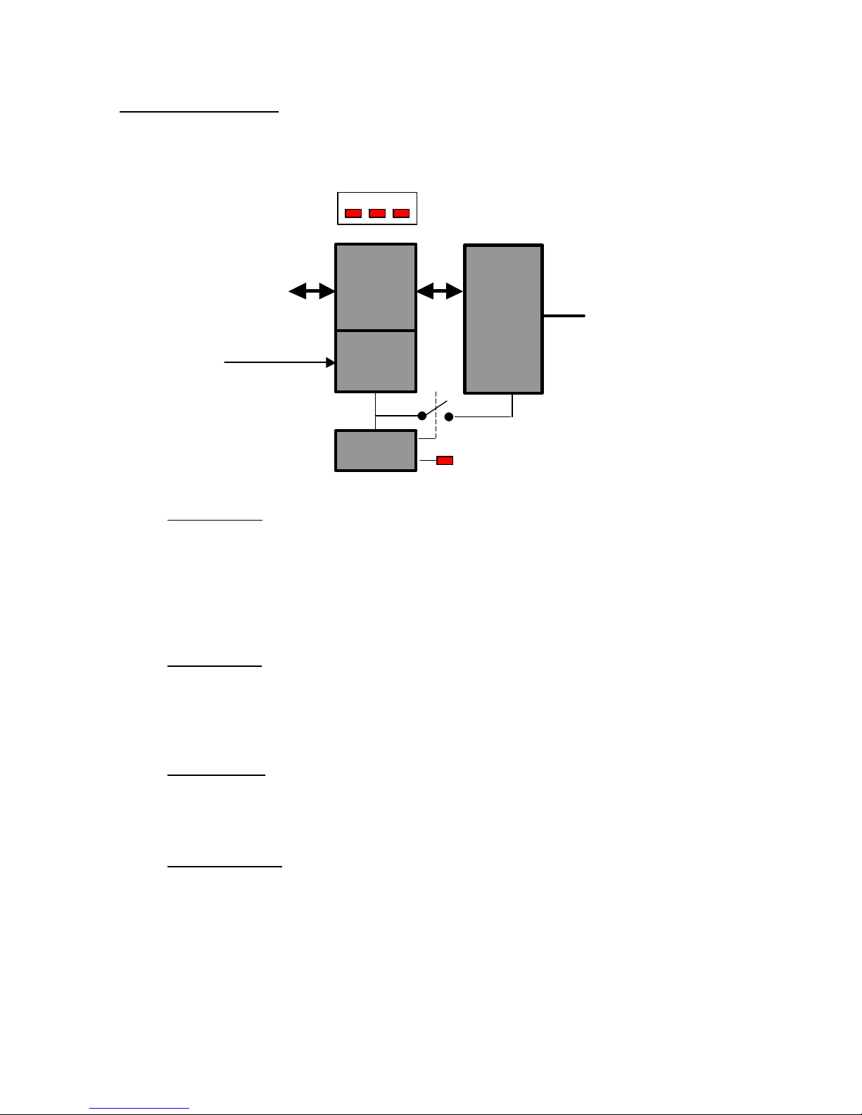
The block diagram below details the location and interconnection of the different
functional units within the modem. The most important units are briefly described.
Power Supply
The power supply (DC) must be connected to the DinBox PSTN(485) modem via a
terminal block with screw contacts. Make sure the voltage supplied to the modem is in
the range of the DinBox PSTN(485) input voltage (see specifications for details on
voltage range).
This input is protected against reversed polarity with a serial diode.
DTE Interface
The DinBox PSTN(485) modem has a RS-232 interface (RJ-45) witch can be
connected to a computer or similar device via included RJ-45/DB-9 serial cable.
The DinBox PSTN(485) has a buid-in 2-wire and 4-wire RS-485 interface.
PSTN Modem
The DinBox PSTN(485) modem has a Conexant modem chip. Connection with the
PSTN network is done via a standard RJ-11 connector.
Watchdog circuit
A long-term watchdog circuit is implemented. The power supply of the PSTN modem will
be disconnected for a few seconds after the selected reset period.
If a part of the DinBox PSTN(485) is ‘locked’ after e.g. an unexpected high ESD
discharge, surge pulse or an internal lock-up, this watchdog will always insure the
continuity of communication.
RS-232
RS-485
10 - 40 Vdc
PSTN
TxD RxD DCD
DTE
Interface
Power
Supply
Watch
DOG
PSTN
Modem
Page 8
DinBox PSTN Reference manual – V1.3
Bausch Datacom NV
8
3. Specifications
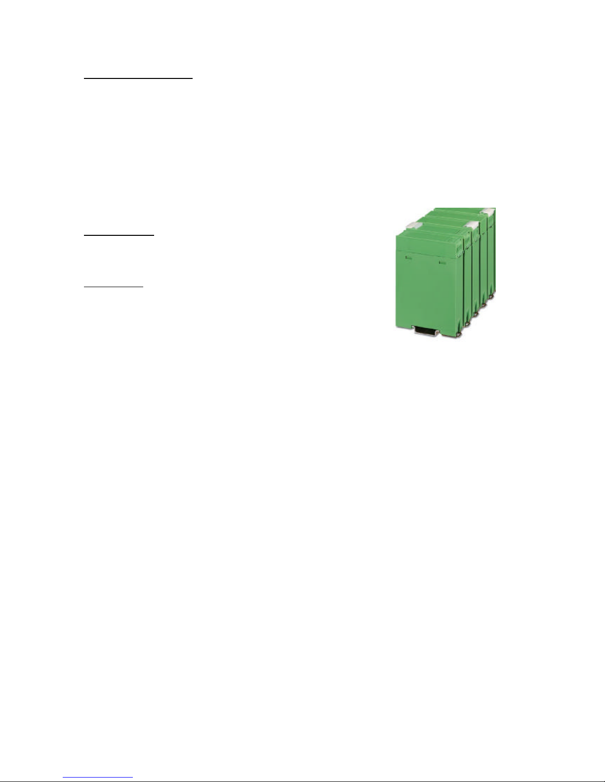
3.1 Housing
Phoenix Contact EG22,5 ABS DIN rail housing
(EG22.5-G/ABS GN + EG22.5-A/ABS GN)
?? 22.5 mm 107.5 mm x 75 mm
?? IP40
?? Symmetrical DIN rail mounting according EN50 022
?? Green color
Standard ABS
Acryl Butadiene Styrene – Tmax = 80 °C
Inflammability class acc. to UL 94 : HB
Optional PC (only on special request)
Polycarbonate – Tmax = 115 °C
metal DIN-rail clip
Inflammability class acc. to UL 94 : V0
Page 9
DinBox PSTN Reference manual – V1.3
Bausch Datacom NV
9
3.2 Connectors
Power Supply 4-pin header (MSTBO2.5/4-GR(L)-5.08)
pitch : 5.08 mm / Inom : 12 A / Unom : 250 V
& Not Used 4-pin plug (MVSTBW2.5/4-ST-5.08)
pitch : 5.08 mm / Inom : 12 A / Unom : 250 V / Max. conductor cross section, flexible : 2.5 mm²
RS-485 4-pin header (MSTBO2.5/4-GR(L)-5.08)
pitch : 5.08 mm / Inom : 12 A / Unom : 250 V
Connections 4-pin plug (MVSTBW2.5/4-ST-5.08)
pitch : 5.08 mm / Inom : 12 A / Unom : 250 V / Max. conductor cross section, flexible : 2.5 mm²
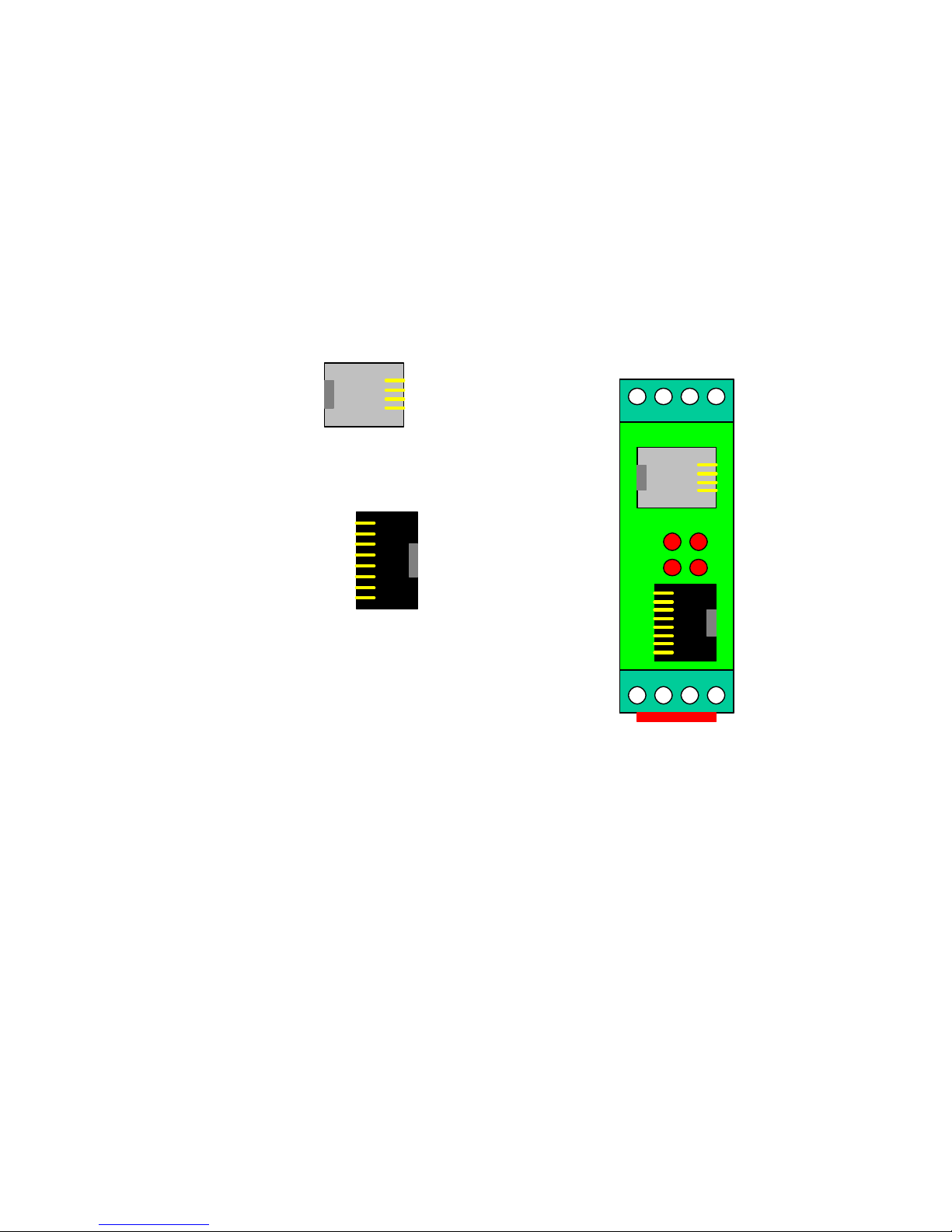
PSTN line RJ-11
Serial DTE RJ-45 8x8 (Molex)
3.3 Environmental conditions
Temperature in use -10°C / + 50°C
Humidity in use 10% - 75% (non condensing)
3.4 Power Supply Specifications
Input voltage range: 10 – 40 Vdc regulated
Typical power consumption : 150mA (Max., Operating on-line)
CTS
RTS
RI
GND
DTR
TXD
RXD
DCD
- +
Power
Supply
x x
Not
Used
RS-485
4 3 2 1
Line
RJ-11
Serial DTE
RJ-45
DCD
WD
RxD
TxD
A’
A
B
B’
Page 10

DinBox PSTN Reference manual – V1.3
Bausch Datacom NV
10
3.5 PSTN modem Specifications
?? ITU-T V.92 with PCM upstream rates up to 48 kbps, QuickConnect and Modem-on-hold functions
?? V.92, V.90, V.34, V.32bis, V.32, V.22 bis, V.22, V.23, and V.21; Bell 212A and Bell 103
?? V.22 bis fast connect
?? V.250 and V.251 commands
?? V.253 commands
?? Data compression and error correction
?? V.44 data compression for optimal downloading of Internet Web pages and files
?? V.42 bis and MNP 5 data compression
?? V.42 LAPM and MNP 2-4 error correction
?? MNP 10EC(tm) enhanced cellular performance
?? Flow control and speed buffering.
?? Automatic format/speed sensing.
?? RS-232 Serial async interface, supports speeds up to 230.4 Kbps
?? 11-bit Direct mode
?? Fax modem
?? V.17, V.29, V.27 ter, and V.21 channel 2
?? EIA/TIA 578 Class 1 and T.31 Class 1.0 commands
?? Upgradeable Flash ROM
?? Data/Fax/Voice call discrimination
?? Hardware-based modem controller and digital signal processor (DSP)
?? Worldwide operation
?? Call progress, blacklisting
?? Distinctive ring detect
?? Caller ID detect
?? Off-hook Call Waiting Caller ID detection during data mode in V.92, V.90, V.34, V.32bis, or V.32
?? 2-bit and 4-bit Conexant ADPCM, 8-bit linear PCM, and 4-bit IMA coding 8 kHz sample rate
?? Concurrent DTMF, ring, and Caller ID detection
?? 2-wire Leased Line
?? Dump mode
?? Asynchrone DTR -dialling
Page 11
DinBox PSTN Reference manual – V1.3
Bausch Datacom NV
11
4. Ports and Connectors
Before you start the installation, take a moment to become more familiar with the
possible connections to and from the DinBox PSTN(485) modem.
Disconnect the mains power before connecting or
disconnecting the power and/or DTE plugs !
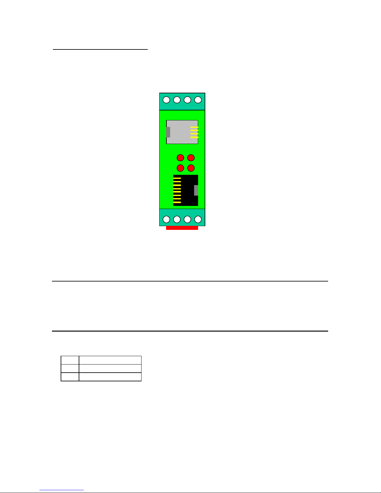
4.1 Power Connection
PIN
+ + DC
- - DC
Always disconnect the mains power before connecting or disconnecting the power.
Make sure the voltage supplied to the modem is in the range of the DinBox PSTN(485)
power supply specification (see specifications for details on voltage range).
-
+
Power
Supply
x x
Not
Used
RS-485
4 3 2 1
Line
RJ-11
Serial DTE
RJ-45
DCD
WD
RxD
TxD
Page 12
DinBox PSTN Reference manual – V1.3
Bausch Datacom NV
12
4.2 Standard DTE Interface
Only devices which are conform with the safety
regulations can be connected to the DTE port!
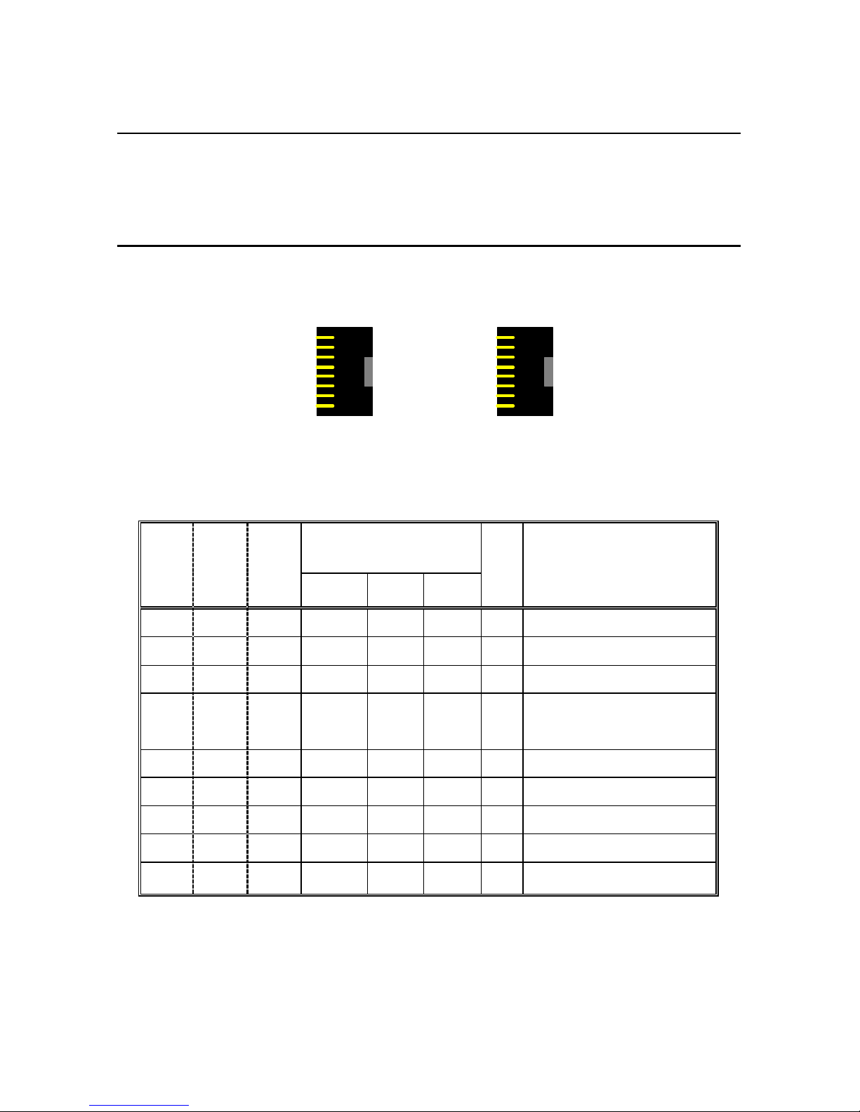
The DinBox PSTN(485) is equipped with a RJ-45 (8x8) connector. This is the serial
interface of the modem.
A Bausch RJ-45 to a standard DB9 (female) cable is delivered with the DinBox
PSTN(485) modem.
EIA/TIA561 pin layout is possible on special request (info in RED).
Pin
RJ45
Pin
RJ45
Pin
DB9
V.24/V.28
I/O
TEXT
Bausch EIA/TIA
561
CCITT
DIN EIA
1 2 1 109 M5 DCD O Data carrier detect
2 5 2 104 D2 R D O Receive data
3 6 3 103 D1 T D I Transmit data
4 3 4 108/1
108/2
S1.1
S1.2
DTR I Data terminal ready
5 4 5 102 E2 GND --- Signal ground
- - 6 107 M1 DSR O Data set ready
7 8 7 105 S2 RTS I Request to send
8 7 8 106 M2 CTS O Clear to send
6 - 9 125 M3 RI O Ring indicator
Output: from DCE (modem) to DTE (terminal)
Input: from DTE (terminal) to DCE (modem)
8 CTS
7 RTS
6 RI
5 GND
4 DTR
3 TXD
2 RXD
1 DCD
8 RTS
7 CTS
6 TXD
5 RXD
4 GND
3 DTR
2 DCD
1 -
Page 13

DinBox PSTN Reference manual – V1.3
Bausch Datacom NV
13
The DinBox PSTN(485) modem will detect the DTE port speed (auto baud), number of
data bits and parity type from the "AT" header that precedes every command (in async
mode).
The &W command automatically saves the baud rate, number of data bits, parity and
number of stop bits.
4.3 PSTN connection
The DinBox PSTN(485) modem has to be connected to a PSTN line via the RJ-11
connector.
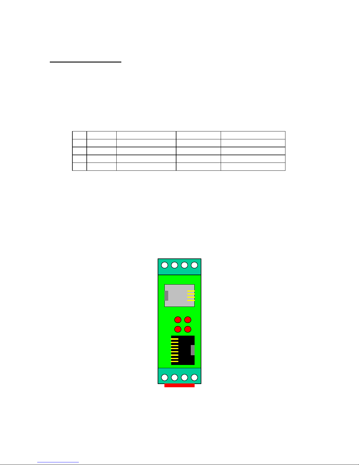
There are 4 pins connected :
A / B ? connection to the telephone network
A’ / B’ ? connection for a parallel connected telephone
A is always connected to A’ and B is always connected to B’. Therefore it is sometimes
necessary to use a 2-wire telephone cable (only 2 wires in the middle) when the DinBox
PSTN(485) is connected to a digital PABX with analogue telephone lines. A’ and/or B’
can be used as signalling lines between the telephone and the PABX.
5. LED indicators
TxD Transmit Data from DTE to modem
RxD Receive Data from modem to DTE
DCD Data Carrier Detect from modem to DCE
WD Watchdog heartbeat 1 sec on/off
6. Watchdog functionality
To prevent a “total lock-up” of the DinBox PSTN(485) a long term watchdog is
implemented. This function is created with a separate RISC micro controller. The micro
controller itself is guarded with it’s own internal watchdog (+/- 1 second refresh / WD
LED flash).
The power supply to the communication control processor and the modem module will
be disconnected for a few seconds after +/- 24 hour IF the modem is NOT connected
(inactive DCD signal).
If the reset period is ended and the modem is connected to a remote host (active DCD
signal) the reset will not be conducted.
If the reset period is ended and the watchdog already past a reset, because of an active
DCD signal, the reset will be conducted after +/- 10 minutes !
Otherwise, if the DinBox PSTN(485) is “locked-up” with an active DCD signal the
watchdog will never be able to reset the WAN module.
A’
A
B
B’
Page 14
DinBox PSTN Reference manual – V1.3
Bausch Datacom NV
14
7. RS-485 interface
The DinBox PSTN(485) has an internal RS-485 4-wire and 2-wire interface. See the
next chapters for more information about the use and setup of this interface.
7.1 External connections
The RS-485 interface must be connected via the screw contacts on the opposite side of
the power connection.
2-wire 2-wire signal flow
4-wire 4-wire signal flow
1
- - RCV/z output – to DTE
2
B in/out XMIT/b input – from DTE
3
A in/out XMIT/a input – from DTE
4
- - RCV/y output – to DTE
See page 4 for the serial V.24 signal flow definitions in this manual. A modem is a DCE
device, receive is output and transmit is input !
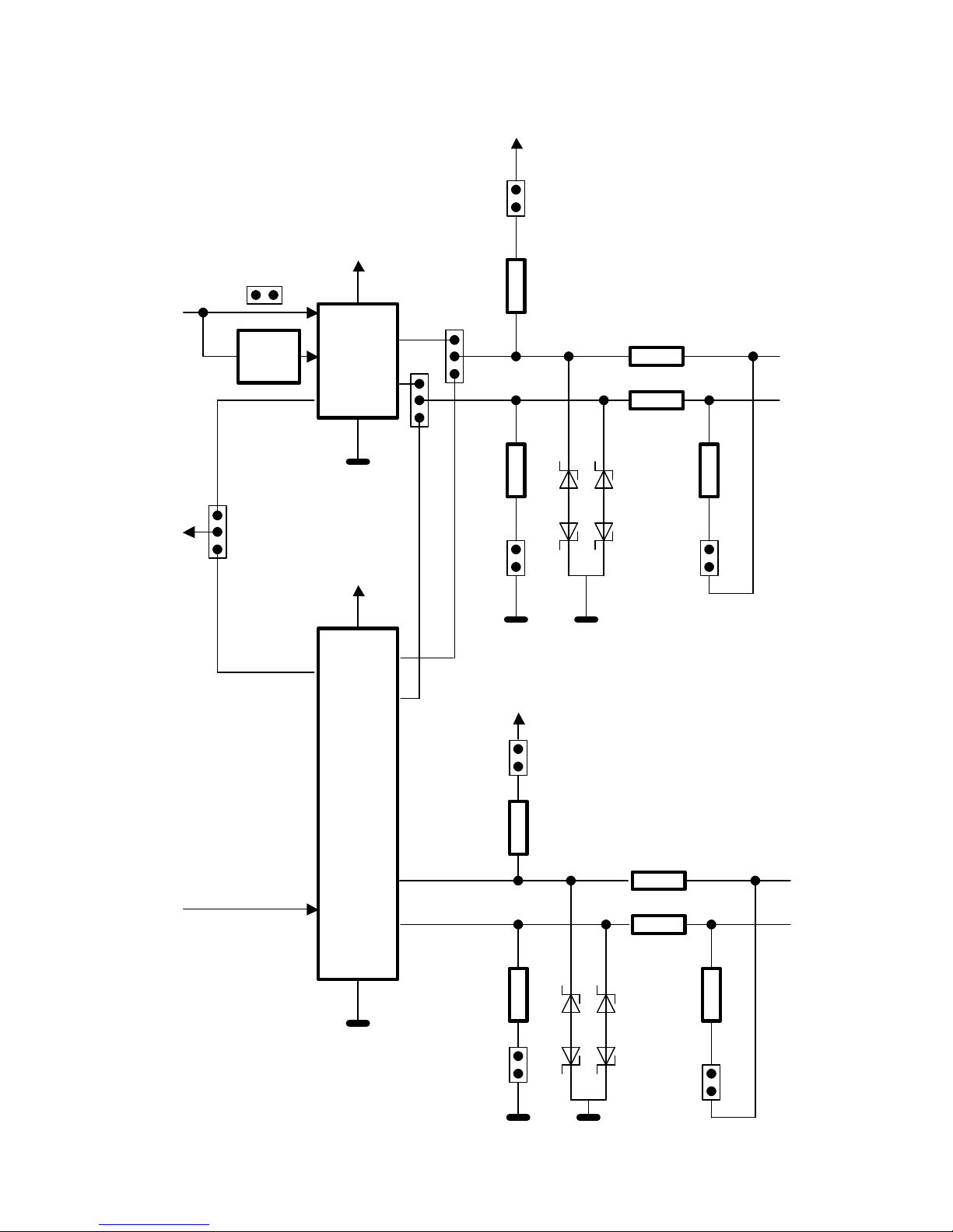
In chapter 7.2 you will find a schematic overview of the RS-485 circuit.
In chapter 7.3 you will find an overview of the possible jumper settings.
-
+
Power
Supply
x x
Not
Used
RS-485
4 3 2 1
Line
RJ-11
Serial DTE
RJ-45
RXD
TXD
DCD
WD
Page 15
DinBox PSTN Reference manual – V1.3
Bausch Datacom NV
15
7.2 Schematic overview of the RS-485 circuit
/RXD B A
receiver
transmitter
47 E
47 E
IO 4
IO 1
560 E
120 E
JP10
JP11
JP9 9V1 4V7
560 E
B A
47 E
47 E
dT
receiver
transmitter
~recEN
traEN
IO 3 IO 2
560 E
120 E
JP2 JP4 JP8 JP3 9V1 4V7
560 E
/RXD Y Z /TXD JP6 JP5 JP7
1 3 1 1 3 3
Page 16
DinBox PSTN Reference manual – V1.3
Bausch Datacom NV
16
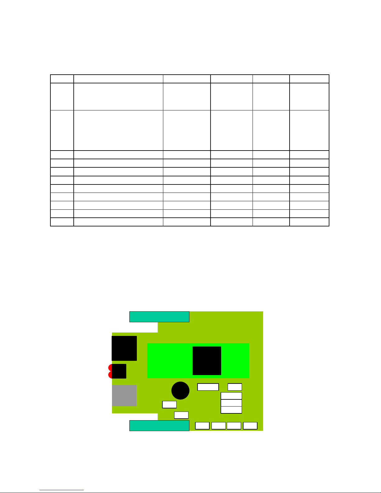
7.3 Possible jumper settings
11 jumpers are to be set for a correct RS-232 / RS-485 interface configuration.
Function 1-2 2-3 Open Close
JP1
How to switch between the
RS-232 and RS-485
interface ?
DTR active
RS -232
DTR not active
RS -485
Always
RS -232
See note(1)
- -
JP2
Delay after sending a
character (DCE > DTE)
and enabling the receiver
again (DTE > DCE, idle
state)
- - +/- 20 ms
1200 bps
2400 bps
4800 bps
+/- 2 ms
>= 9600 bps
See note(2)
JP3
Termination ? line 2-3
- - No resistor 120 E
JP4
+ onto line 3
- - - + connected
JP5
B line switch
2-wire 4-wire - -
JP6
A line switch
2-wire 4-wire - -
JP7
/TXD switch
2-wire 4-wire - -
JP8
- onto line 2
- - - - connected
JP9
Termination ? line 1-4
- - No resistor 120 E
JP10
+ onto line 4
- - - + connected
JP11
- onto line 1
- - - - connected
(1) The DTR signal is not active when the DTE – DCE connection is done by using a 3wire RS-232 interface (RXD, TXD and GND). Use JP1 position 2-3 to lock the RS-232
interface. By default JP1 position 1-2 is used : when the DTR is active, f.e. during
configuration of the DinBox PSTN(485), the RS-232 interface is active. If no DTR, the
RS-485 interface is active.
(2) It is preferred to disable autosensing and lock the interface speed with the +IPR
command when the baudrate is higher or equal then 9600 bps.
1 JP1 3
3 JP7 1
3 JP6 1
3 JP5 1
JP2 JP3 JP9 JP11
JP8 JP4 JP10
Page 17

DinBox PSTN Reference manual – V1.3
Bausch Datacom NV
17
7.4 Example conf iguration for RS-485 communication
The RS-485 interface must be connected via the screw contacts on the opposite side of
the power connection.
Connect a terminal (PC) to the RS-232 interface (RJ45). The DinBox PSTN(485) will
automatically switch to the RS-232 interface if DTR is present (JP1 on 1-2 position).
Verify the correct communication parameters, for example 9600 8N1.
Send the commands below to the DinBox PSTN(485) modem.
at&f ‘ factory reset
at+ipr=9600 ‘ autosensing off, lock on 9600 bps
at&d0 ‘ no DTR
at&k0 ‘ no RTS / no flow control
atk0 ‘ dump mode
ats0=0 or x ‘ no answer (0) or answer after x rings
ate0 ‘ local echo off
at&w ‘ save in NVRAM
It’s important to disable local echo (ate0) when RS-485 2-wire is used !
Page 18

DinBox PSTN Reference manual – V1.3
Bausch Datacom NV
18
8. AT Command interface
8.1 Standard command overview
The configuration of the DinBox PSTN(485) is done by sending AT command to the
modem, changing S-registers into the modem and interpreting the responses sent by
the modem.
We have added the original Conexant reference manual onto the CD-ROM.
Below you will find a overview of all the possible command and S-registers.
Data Commands 3-2
Generic Modem Control 3-2
Z - Soft Reset and Restore Profile 3-2
+FCLASS - Select Active Service Class 3-2
+VCID - Caller ID (CID) 3-3
+VRID - Report Retrieved Caller ID (CID) 3-4
\N - Operating Mode 3-5
I - Identification 3-6
+GMI - Request Manufacturer Identification 3-7
+GMI9 - Request Conexant Identification 3-7
+GMM - Request Model Identification 3-8
+GMR - Request Revision Identification 3-8
+GCAP - Request Complete Capabilities List 3-8
+GCI - Country of Installation 3-9
&F - Restore Factory Configuration (Profile) 3-10
&T - Local Analog Loopback Test 3-10
&Y - Designate a Default Reset Profile 3-11
&W - Store Current Configuration 3-11
&Zn=x - Store Telephone Number 3-12
%7 - Plug and Play Serial Number 3-12
%8 - Plug and Play Vendor ID and Product Number 3-13
**- Load Flash Memory 3-14
DTE-Modem Interface commands 3-17
E - Command Echo 3-17
Q - Quiet Results Codes Control 3-17
V - Result Code Form 3-18
W - Connect Message Control 3-18
X - Extended Result Codes 3-19
&C - RLSD (DCD) Option 3-24
&D - DTR Option 3-24
&K - Flow Control 3-25
&M - Asynchronous/Synchronous Mode Selection 3-26
&Q - Sync/Async Mode 3-27
&R - RTS/CTS Option 3-28
&S - DSR Override 3-28
&X - Select Synchronous Clock Source 3-29
+IPR - Fixed DTE Rate 3-30
+IFC - DTE -Modem Local Flow Control 3-31
+ILRR - DTE -Modem Local Rate Reporting 3-32
+IBC – In Band Commands 3-34
Call Control 3-37
D - Dial 3-37
T - Set Tone Dial Default 3-40
P - Set Pulse Dial Default 3-40
A - Answer 3-40
Page 19

DinBox PSTN Reference manual – V1.3
Bausch Datacom NV
19
H - Disconnect (Hang-Up) 3-41
O - Return to On-Line Data Mode 3-42
L - Speaker Volume 3-43
M - Speaker Control 3-43
&G - Select Guard Tone 3-44
&P - Select Pulse Dial Make/Break Ratio 3-44
&V - Display Current Configuration and Stored Profiles 3-45
&V1 - Display Last Connection Statistics 3-46
\V - Single Line Connect Message Enable 3-47
%L - Report Line Signal Level 3-48
%Q - Report Line Signal Quality 3-48
*B - Display Blacklisted Numbers 3-48
*D - Display Delayed Numbers 3-49
–PPD= - Extension Pickup Notification through 16550 UART 3-49
–STE= - Set Telephony Extension 3-50
-TRV – Tip & Ring Voltage 3-55
-TTE - Threshold Adjustments for Telephony Extension 3-56
Modulation Control Commands 3-57
+MS - Modulation Selection 3-57
+MR - Modulation Reporting Control 3-59
%E - Enable/Disable Line Quality Monitor and
Auto-Retrain or Fallback/Fall Forward 3-61
B - CCITT or Bell 3-62
Error Control Commands 3-63
+ES - Error Control and Synchronous Mode Selection 3-63
+EB - Break Handling in Error Control Operation 3-65
+ESR - Selective Repeat 3-65
+EFCS - 32-bit Frame Check Sequence 3-66
+ER - Error Control Reporting 3-67
+ETBM - Call Termination Buffer Management 3-69
\B - Transmit Break to Remote 3-70
\K - Break Control 3-71
-K - MNP Extended Services 3-72
Data Compression Commands 3-73
+DS - Data Compression 3-73
+DS44 - V44 Compression Select 3-74
+DR - Data Compression Reporting 3-75
%C - Enable/Disable Data Compression 3-77
V8/V8bis Commands 3-78
+A8E - V8 and V8bis Operation Controls 3-78
+A8I: - CI Signal Indication 3-79
Synchronous Access Mode Commands 3-80
+ESA - Configure Synchronous Access Submode 3-80
+H - Enable/Disable RPI 3-82
+ITF - Transmit Flow Control Thresholds 3-83
Diagnostic Commands 3-84
#UD – Last Call Status Report 3-84
%TT - PTT Test Command 3-92
Compatibility Commands 3-93
&L - Leased Line Operation 3-93
)M - Enable Cellular Power Level Adjustment 3-93
@M - Initial Cellular Power Level Setting 3-94
:E - Compromise Equalizer Enable Command 3-94
Fast Connect Commands 3-95
Page 20

DinBox PSTN Reference manual – V1.3
Bausch Datacom NV
20
$F – Fast Connect Control 3-95
V92 +P and –Q Commands 3-96
+PCW - Call Waiting Enable 3-96
+PMH - Modem-on-Hold Enable 3-97
+PMHT – Modem-on-Hold Timer 3-98
+PMHR - Initiate Modem-on-Hold 3-99
+PIG - PCM Upstream Ignore 3-100
+PMHF - V92 Modem-on-Hold Hook Flash 3-100
+PQC - V92 Phase 1 and Phase 2 Control 3-101
+PSS - Use Short Sequence 3-102
-QCPC - Force Full Startup Procedure Next Connection 3-103
-QCPS - Enable Quick Connect Profile Save 3-103
S-Parameters 3-104
S0 - Number of Rings to Auto-Answer 3-106
S1 - Ring Counter 3-106
S2 - Escape Character 3-106
S3 - Carriage Return Character 3-106
S4 - Line Feed Character 3-106
S5 - Backspace Character 3-107
S6 - Wait Time before Blind Dialing or for Dial Tone 3-107
S7 - Wait Time for Carrier, Silence, or Dial Tone 3-107
S8 - Pause Time For Dial Delay 3-108
S9 - Carrier Detect Response Time 3-108
S10 - Lost Carrier To Hang Up Delay 3-108
S11 - DTMF Tone Duration 3-108
S12 - Escape Prompt Delay (EPD) 3-109
S14 - General Bit Mapped Options Status 3-109
S16 - Test Mode Bit Mapped Options Status 3-109
S17 - Point Of Sale Options Selection 3-110
S19 - Reserved 3-111
S20 - Reserved 3-111
S21 - V24/General Bit Mapped Options Status 3-112
S22 - Speaker/Results Bit Mapped Options Status 3-112
S23 - General Bit Mapped Options Status 3-113
S24 - Sleep Inactivity Timer 3-113
S25 - Delay To DTR Off 3-113
S26 - RTS to CTS Delay 3-113
S27 - Bit Mapped Options Status 3-114
S28 - Bit Mapped Options Status 3-114
S29 - Flash Dial Modifier Time 3-115
S30 - Disconnect Inactivity Timer 3-115
S31 - Bit Mapped Options Status 3-115
S36 - LAPM Failure Control 3-116
S38 - Delay Before Forced Hang Up 3-116
S39 - Flow Control Bit Mapped Options Status 3-117
S40 - General Bit Mapped Options Status 3-117
S41 - General Bit Mapped Options Status 3-118
S46 - Data Compression Control 3-118
S48 - V42 Negotiation Control 3-118
S86 - Call Failure Reason Code 3-119
S91 - PSTN Transmit Attenuation Level 3-120
S92 - Fax Transmit Attenuation Level 3-120
S95 - Extended Result Codes Control 3-120
S210 – V34 Symbol Rates 3-121
Page 21

DinBox PSTN Reference manual – V1.3
Bausch Datacom NV
21
Result Codes 3-122
FaxClass1 and FaxClass10 Commands 4-1
Commands and Parameters 4-6
Mode Entry Commands 4-6
+FCLASS=1 - Select Facsimile Class 1 Mode 4-6
+FCLASS=10 - Select Facsimile Class 10 Mode 4-6
Mode Commands 4-6
+FAA - Auto Answer Enable 4-6
+FAE - Auto Answer Enable 4-7
+FTS - Transmit Silence 4-7
+FRS - Receive Silence 4-8
+FTM - Transmit Facsimile 4-9
+FRM - Receive Facsimile 4-10
+FTH - Transmit Data with HDLC Framing 4-11
+FRH - Receive Data with HDLC Framing 4-12
Service Class 1 Parameters 4-13
+FAR - Adaptive Reception Control 4-13
+FCL - Carrier Loss Timeout 4-14
+FDD - Double Escape Character Replacement 4-15
+FIT - DTE Inactivity Timeout 4-16
+FPR - Fixed DTE Rate 4-17
+FMI? - Request Manufacturer Identification 4-18
+FMM? - Request Model Identification 4-18
+FMR? - Request Revision Identification 4-18
+FLO - Flow Control 4-19
Configuration Commands 5-4
+FCLASS=8 - Select Voice Mode 5-4
+VNH - Automatic Hang-up Control 5-4
Voice Commands 5-5
+VIP - Voice Initialize All Parameters 5-5
+VRX - Start Modem Receive (Record) 5-5
+VTR - Start Voice Transmission and Reception (Voice Duplex) 5-6
+VTS - Send Voice Tone(s) 5-7
+VTX - Start Modem Transmit (Playback) 5-9
+VGR - Voice Gain Receive (Record Gain) 5-9
+VGT - Voice Gain Transmit (Playback Volume) 5-10
+VIT - Voice Inactivity Timer (DTE/Modem) 5-11
+VLS - Analog Source/Destination Selection 5-11
+VRA - Ringback Goes Away Timer 5-15
+VRN - Ringback Never Appeared Timer 5-16
+VSD - Silence Detection (Quiet and Silence) 5-17
+VSM - Compression Method Selection 5-18
+VTD - Beep Tone Duration Timer 5-19
+VDR - Distinctive Ring 5-20
+VDT - Control Tone Cadence Reporting 5-21
+VPR - Select DTE/Modem Interface Rate (Turn Off Autobaud) 5-22
Speakerphone Commands 5-23
+VSP - Speakerphone ON/OFF 5-23
+VDX - Speakerphone Duplex Mode 5-24
+VGM - Microphone Gain 5-25
+VGS - Speaker Gain 5-26
Page 22

DinBox PSTN Reference manual – V1.3
Bausch Datacom NV
22
8.2 Enhanced features
8.2.1 Dump mode
When the DinBox PSTN(485) receives a character from the DTE, during the call setup
and/or speed negotiation, the modem will stop all further negotiations and will go off-line.
We have added ‘dump mode’ to prevent this.
atk1 stop negotiation when a character is received
atk0 dump mode active
8.2.2 Leased Line configuration
It’s possible to configure the DinBox PSTN(485) modem as a 2-wire leased line modem.
This point-to-point setup has always an originate and an answer side.
What do you have to know before you start configuring the modems :
Specification of the DTE port :
If asynchronous what is the used speed ? eg. 9.600 bps
data / parity / stop bits ? eg. 8 N 1
flow control ? eg. RTS/CTS
is DTR supported ?
If synchronous is DTR supported ?
To configure the modems you can use a st andard terminal software package. If the DTE uses
asynchronous communication it is very important to use the same baudrate as the DTE port
when the modem is configured.
This asynchronous baudrate will be saved when the modem receives the AT&W command.
ANSWER
Information
ORIGINATE
at&f
factory reset
at&f
at&L1
enable leased line
at&L1
ats0=1
answer/originate
ats0=0
ats7=30
reset cycle
ats7=25
atk0
dump mode
atk0
at&d0
if DTR is NOT supported
at&d0
at&k0
if NO flow control
at&k0
at&k4
if XON/XOFF flow control
at&k4
at&k3
if RTS/CTS flow control
at&k3
at&m1
if synchronous DTE
at&m1
at&w
save config in NVRAM
at&w
Page 23
DinBox PSTN Reference manual – V1.3
Bausch Datacom NV
23
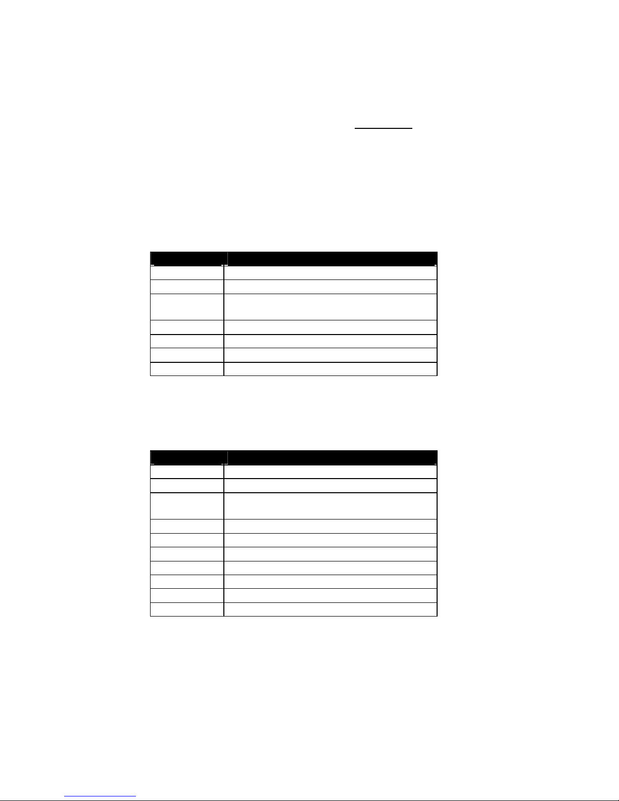
It is possible to change the transmit level with register S91. Default transmit level is –10 dBm.
How to reset the mo dem after a leased line configuration :
?? Connect an asynchronous terminal to the DTE port of the modem.
?? You have to run a standard terminal software package on the same baudrate as you have
used for configuring the same modem for leased line.
?? At this time it is possible to give a full reset command (at&f&w) just after (within 3 seconds)
you switch on the modem.
8.2.3 Asynchronous DTR-dialing
The modem will automatically dial the saved number if DTR is changing from an inactive to an
active state when asy nchronous DTR-dialing is active.
commands
Information
at&f factory reset
at&q7 enable asynchronous DTR-dialling
at&z0=x save telephone number in slot 0
x = telephone number
at&v to verify the saved number
at&w save configuration in NVRAM
8.2.4 Selective CID answer
The modem will ONLY automatically answer a call from one predefined telephone number.
commands
Information
at&f factory reset
at+vcid=1 enable CID
at&z0=x save telephone number in slot 0
x = telephone number
at&v to verify the saved number
atc1 enable selective CID answer
ats0=0 disable automatic answer
at&w save configuration in NVRAM
! This option is available from version 2 (ati4) or more recent.
Page 24
DinBox PSTN Reference manual – V1.3
Bausch Datacom NV
24
Page 25
DinBox PSTN Reference manual – V1.3
Bausch Datacom NV
25
Page 26

DinBox PSTN Reference manual – V1.3
Bausch Datacom NV
26
EC-Declaration of conformity Artists in data communication
According to the provisions of the 1999/5/EC Directive,
covering all essential requirements.
We, Bausch Datacom
Tiensesteenweg 54-56
BE-3360 Korbeek-Lo
Belgium
Name and address of the manufacturer or the introducer of the product on the market who is established in the EC
herewith take the sole responsibility to confirm that the product:
PSTN-modem: DinBox PSTN(485)
Type designation and, if applicable, Article -No.
which refers to this declaration, is in accordance with the following standards or
standardized documents:
The following operation conditions and installation arrangements have to be
resumed:
Acc. To Operating Manual
Name, address, date and legally binding signature of the person responsible
NBN EN 61000
-4-
2 Electrostatic discharge (ESD)
NBN EN 61000-4-3 Electromagnetic HF fields (Radiated Immunity)
NBN EN 61000-4-4 Fast transients (EFT/B)
NBN EN 61000-4-5 Surges
NBN EN 61000-4-6 Injected currents (Conducted RF)
NBN EN 61000-4-8 Power Frequency Magnetic
NBN EN 61000-4-11 Voltage dips and interruptions (PQF)
ENV 50204 Electromagnetic HF fields
NBN EN 61000-3-2(1995) Harmonic Current Emission
NBN EN 61000-3-3(1994) Limitation of voltage flicker
NBN EN50204 (1995) Immunity / RCLI
NBN EN55011 (1998) + A1 (1999) Electromagnetical disturbance: medical, industrial and
scientific appl
ications
 Loading...