

Page 1
SPECTRONIC
21
MV
SPECTROPHOTOMETER
WAVELENGTH
The
MV
model
Figure
wavelength
READOUT
The
linear
bance.
tance
tance.
devices
ACCESSORIES
The
2.
3.
4.
5.
6.
Wavelength
Wavelength
Wavelength
Wavelength
1,
uses
atungsten
range
54”
meter
in
transmittance,
The
meter
with
linear
An
analog
to
record
instrument
1.
Universal
Spare
One
Operator’s
Dust
Calibration
7.
Occluder
8.
Adapter
SPECIFICATIONS
Spectral
test
tungsten
dozen
10mm
manual
cover
screwdriver
block
for
Range
Accuracy
Readability
Repeatability
Slitwidth
RANGE
of
the
SPECTRONIC
lamp
of
340-1000nm.
is
mirrored
and
scale
reads
scale
divisions
output
results
SUPPLIED
is
supplied
tube
lamp
rectangular
permits
in
holder
pathlength
to
provide
to
prevent
is
also
from
00.0
at
the
percent
complete
test-tube
cuvettes
340-1000nm
Better
365nm
1.0nm
Better
10nm
21
series,
an
parallax
calibrated
to
every
use
transmittance.
with:
than
and
than
shown
uninterrupted
error,
in
absor-
100% transmit-
1%
transmit-
of
recording
cuvettes
2nm
at
546nm
Inm
in
is
Stray
Radiant
Photometric
Photometric
Photometric
Photometric
Photometric
Long-term
Zero
Accessory
Dispersing
Power
Voltage
Size
Weight
Drift
Drift
Output
Element
Consumption
Reguirements
Energy
Readout
Range
Noise
Linearity
Accuracy
0.05%
(typical)
5%”
meter,
linear
transmittance
non-linear
mirrored
0-100%T,
Less
Better
meter
Better
analog
Better
analog
0.003A
Less
Analog
(adjustable)
Reflection
lines
40
Watts
Selectable:
220V,
144" W x
(36.8em W x
21.6cm
Add
for
General
Sample
16
lbs.
Add
General
Compartment.
absorbance
scale
0-2A
than
0.1%T
than
1.0%T
than
0.2%T
output
than
0.3%T
output
per
hour
than
0.1%T
in
%T, 1 volt
grating,
/mm
100V,
240V;
50,
104"
H)
5%”’
(14cm)
Purpose
Compartment.
(7.3kg)
3%
lbs.
(1.6kg)
Purpose
at
340nm
(T),
(A),
near
100%T
at
at
at
per
day
1200
115V,
60
Hz
Dx
84"
26.7em D x
to
width
for
Sample
H
DSC
|
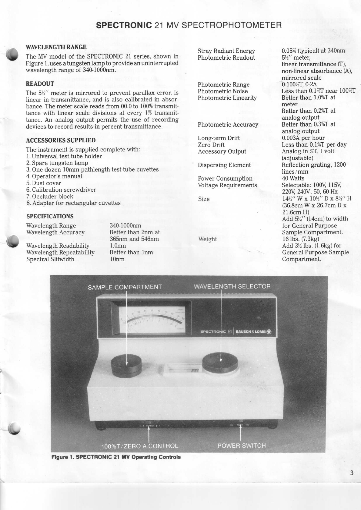
Figure
1.
SPECTRONIC
100%T/ZERO
21
MV
A
CONTROL
Operating
Controls
POWER
SWITCH
Page 2
Power
Consumption
Voltage
Requirements
Size
Weight
OPERATING
Before
tion
this
Conversion
Operating
using
as
described
The
voltage
1.
Plug
2.
Turn
right
instrument
on,
best
period
Display
instrument
controls
the
the
side
performance
of
characters
normal.
3.
Select
the
selector.
the
left
of
4.Choose
length
pathlength
for
samples.
5.
Open
the
6.
Fill
one
cuvette
sample
compartment.
solution
through
provided
proper
is
fill
provided
compartment.
a.
Solution
standard
adaptor).
b.
Solution
tube
cuvette
7.
Close
the
8.Select
bance,
9.
Set
lower
the
or
the
SENSITIVITY
control
45
Watts
Selectable:
240V;
14%" W x
(36.8cm x 26.7cm x 21.6cm)
Add
General
Compartment
16%
Add
Purpose
PROCEDURES
the
instrument,
in
the
check
Maintenance
NOTE
is
set
to
is
not
correct
instructions
are
instrument
instrument
of
the
can
be
15
to
30
for
in
the
shown
into a grounded
on
using
lower
control
used
almost
is
achieved
minutes.
NOTE
may
be
slow
to
turn
during
desired
Wavelength
the
matched
the
cuvettes
sample
first
minute
wavelength
is
indicated
wavelength
cuvettes
analytical
for
compartment
with a blank
Fill
to
completely
the
sample
cover
compartment.
with a horizontal
level. A vertical
for
alignment
with
NOTE
level
must
be
cuvette
level
sample
operating
concentration—using
(10
cm
must
be
(used
with
compartment
mode—transmittance,
at
switch
panel
to
LO.
100V,
50,
60
Hz
10%
5%’
(14cm)
Purpose
lbs.
(7.5kg)
3%
lbs.
(1.6kg)
Sample
the
section.
operate
on a 115VAC
your
line,
Maintenance
in
Figure
the
POWER
panel.
as
soon
following a warmup
on,
or
of
with
on
selector.
of
the
method.
all
blanks,
door.
solution and
the
cuvette
the
light
fiducial
fiducial
at
the
least
square;
least
32
mark
mark
mark
universal
cover.
the
located
115V,
220V,
Dx
8%
Η
to
width
Sample
for
General
Compartment
electronic
see
calibra-
the
Voltage
section.
2.
outlet.
switch
Although
as
it
is
may
have
unusual
operation.
the
wavelength
the
dial
located
appropriate
Use
the
sample
standards,
insert
with
enough
beam
passing
Some
cuvettes
to
indicate
on
the
cuvette
on
the
sample
20
mm
high
used
with
mm
high
in a test
test
tube
holder).
mode
selector.
in
the
center
for
line.
If
on
the
the
turned
This
is
to
path-
and
it
in
the
are
the
in
a
cuvette
absor-
of
the
10.SET
11.
12.
100%T,
100%T
/zero A control
lower
control
100%T,
000A
ITY
switch
position.
to
Any
acceptable.
adjustment
reset
the
100%T
reset
the
SENSITIVITY
Remove
Fill
solution
under
each
the
the
of
or
sample
heading
000A,
or
(The
for
blank.
the
using.
Absorbance
13.
Turn
tance
turn,
cording
most
linear
conveniently
14.
Construct a standard
on
solution
15.
Determine
the
and
the
16.
Correct
or
Transmittance
MODE
and
into
SELECTOR
insert
the
absorbance
analytical
than
transmittance
utilized.)
the
y-axis
on
the
the
absorbance
reading
the
x-axis.
for
any
necessary.
Concentration
standard
13.
Turn
standard
14.
Using
tion
value
with
other
CONC.
check
15.
Insert
results
16.
The
decimal
or O decimal
operates
trolled
of
the
Each
point
moves
the
zero
disappears).
turns
If
is
in
the
effect.
concentration
mal
setting
turned
to
the
Mode
curve
has
MODE
solution
the
CONC.
of
the
standard
FACTOR
and
record
samples
directly
select
places
in
the
by
the
digital
time
one
decimal
Pressing
the
decimal
the
pushbutton
transmittance
When
will
off,
turning
zero
decimal
or
000C
located
panel.
If
there
000C
on
the
the M (medium)
position
at
which
SENSITIVITY
the
100%T
/zero A control
switch.
matched
to
cuvettes
be
measured.
appropriate
to
each
sample
sample
purposes
compartment,
or
transmittance
absorbance
curve
vs.
the
concentration
x-axis.
concentration
or
transmittance
corresponding
sample
SELECTOR
blank
(use
be
verified).
in
the
ADJUST
standard
only
to
sample
on
solutions
CHECK
in
in
button
test
conditions
the
sample
concentration
feature
on
the
concentration
DECIMAL
SELECT
display:
the
pushbutton
place
to
the
place
is
reached
the
pushbutton
point
to
is
pressed
or
absorbance
the
instrument
mode,
the
still
be
it
back
previous
in
on
position
for
the
blank using
on
the
left
side
is
not
enough
blank,
move
or,
if
necessary,
100%T
switch
/zero A control.)
each
energy
the
can
is a coarse
time
with
the
SENSITIV-
Be
Proceed
to
the
mode
Mode
absorbance
or
standard
or
solution,
reading
values.
values
values
by
and
plotting
the
of
of
each
sample
value
concentration
or
interference
if
the
linearity
can
absorbance
each
by
on
the
concentration.
compartment.
control,
the
set
the
digital
display.
for
verification.
can
be
depressed
(see
Appendix
concentra-
compartment
units.
permits
digital-display.
selection
mode
only
The
and
pushbutton
is
right
the
pressed,
on
third
while
the
(the
decimal
once
place.
the
the
display
instrument
mode,
is
switched
effect.
resets
(no
point
concentration
If
back
the
instrument
the
decimal
visible).
the
of
the
to
set
to
the
HI
be
set
is
sure
to
that
you
standard
to
step
13
you
are
transmit-
in
the
re-
(For
are
more
be
more
standard
finding
y-axis
value
off
effects
of
the
Place
as
a
Repeat
The
to
A).
and
read
of
3,
2,
1,
feature
is
con-
at
the
left
decimal
until
point
more
re-
it
has
no
to
the
deci-
is
point
Page 3
yor
WAVELENGTH
The
UVD
Figure
tungsten
length
READOUT
The
modes:
three-position
control
For
digit
for
concentration
provides a readout
concentration
ACCESSORIES
The
1.
2.
3.
4.
5.
6.
7.
8.
SPECIFICATIONS
Wavelength
Wavelength
Wavelength
3,
range
digital
transmittance,
let
values
position
overrange.
The
instrument
Universal
Spare
One
dozen
Operator's
Dust
cover
Calibration
Occluder
Adapter
RANGE
model
has
and
concentration
tungsten
of
an
external
deuterium
of
200-1000nm.
display
SENSITIVITY
you
select
outside
will
units. A CONC.
mode.
SUPPLIED
is
test
tube
10mm
manual
screwdriver
block
for
rectangular
Range
Accuracy
Readability
SPECTRONIC
the
SPECTRONIC
lamp
house,
lamps which
lets
you
read
absorbance,
switch
the
desired
the
photometric
display a “u”
mode
of
the
concentration
supplied
lamp
pathlength
complete
holder
cuvettes
200-1000nm
Better
365nm,
Better
21
containing
in
any
of
or
and
instrument
range,
for
underrange
yields
FACTOR
test
tube
than
and
than
results
with:
21
UVD
series,
provide a wave-
concentration.
the
factor
2nm
three
operating
100%T
gain
the
directly
CHECK
when
cuvettes
at
546nm
1.0nm
shown
both
the
/zero
setting.
left-hand
or
an
“o”
button
in
the
254nm,
SPECTROPHOTOMETER
in
A
A
in
Spectral
Stray
Photometric
Photometric Range
Photometric
Photometric
Photometric
Long-term
Zero
Accessory
Monochromator
Dispersing
Power
Voltage
Size
Slitwidth
Radiant
Drift
Drift
in
Transmittance
Output
Element
Consumption
Requirements
Energy
Readout
Noise
Linearity
Accuracy
(T)
10nm
0.05%
(typical)
Digital
for
absorbance
concentration
A
(concentration
00.0-100.0
0.000-1.990
000-1990
Less
Better
0.4A)
Better
0.4A)
0.003A
Less
Analog
(adjustable),
Positive
Crossed
Reflection
lines
60
Selectable:
240V;
20°
(50.8cm x 26.7cm x 21.6cm).
Add
for
Sample
display,
transmittance
to C conversion
than
than
than
per
than
/mm
Watts
50,
Wx
54
General
at
340nm
selectable
(T),
(A),
or
(C),
and
factor
factor)
in
T
in
A
in
C
0.1
near
100%T
0.001
near
0.002
near
0.2%T
(0.002A
0.3%T
(0.003A
hour
0.1% per
in
%T, 1 Volt
True
Czerny-Turner
grating,
100V,
60
10%
(14cm)
Purpose
Compartment
BCD,
Logic
Hz
Dx
day
TTL
115V,
84
to
width
0.00A
1.00A
at
at
1200
220V,
Η
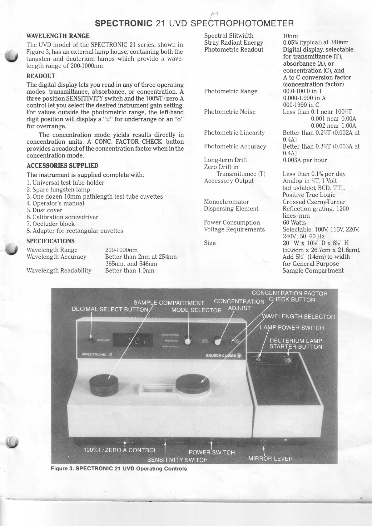
CONCENTRATION
SAMPLE
DECIMAL
Figure
3.
SPECTRONIC
SELECT
100%T/ZERO
BUTTON
+
A
21
UVD
CONTROL
Operating
COMPARTMENT
MODE
SENSITIVITY
Controls
SELECTOR
POWER
SWITCH
CONCENTRATION
ADJUST
WAVELENGTH
LAMP
>
У
SWITCH
—
7
MIRROR
CHECK
POWER
TERIUM
一
LEVER
FACTOR
BUTTON
SELECTOR
SWITCH
LAMP
一
Page 4
Se
™
Weight
OPERATING
—
”
Before
tion
this
Conversion
Operating
1.
Plug
2.
Turn
right
instrument
on,
of
3.
Select
selector.
the
set
4.
Adjust
pulling
lamp
the
5.
Choose
by
or
6.
Ignite
button
deuterium
minutes
stability
red
used.
blue
used.
alternate
which
when
7.Choose
length
length
ment
silica"
8.
Open
9.
Fill
sample
solution
through
provided
proper
is
compartment.
PROCEDURES
m
using
the
as
described
The
instrument
voltage
is
not
instructions
controls
the
instrument
the
instrument
side
of
can
best
performance
15
to
30
minutes.
the
desired
Wavelength
left
of
the
in
the
range
the
mirror
the
mirror
(UV)
and
tungsten
flipping
the
the
lamp
correct
DEUTERIUM-UV.
the
deuterium
for
approximately
lamp
before
takes
The
portion
line
indicates
The
portion
line
indicates
The
portion
red
provides
no
sample
matched
for
the
cuvettes
The
glass
are
usable
cuvettes
the
sample
one
cuvette
compartment.
to
completely
the
sample
with a horizontal
fill
level. A vertical
provided
for
22%
Ibs.
Add
3%
General
Compartment
instrument,
in
the
check
Maintenance
NOTE
is
set
to
operate
correct
are
the
be
for
in
the
shown
on,
lower
used
in
into a grounded
using
control
almost
is
achieved
wavelength
is
indicated
wavelength
selector.
200-1000nm.
position
lever
out
pushing
the
mirror
(VIS).
lamp
for
lamp
power
lamp
2seconds
requires a warm-up
readings
are
longer.
of
the
wavelength
that
the
of
the
wavelength
that
the
deuterium
of
the
wavelength
and
blue
marks
the
most
energy
is
in
place)
cuvettes
analytical
for
all
blanks,
method.
NOTE
test
tubes
supplied
only
above
must
be
used
compartment
with a blank
Fill
cover
compartment.
fiducial
fiducial
alignment
with
(10.2kg).
lbs.
(1.6kg)
Purpose
the
electronic
section.
on a 115
your
line,
see
Maintenance
Figure
the
3.
outlet.
POWER
panel.
as
soon
following a warm-up
with
the
on
the
dial
Wavelength
for
the
lamp
when
using
the
lever
in
the
selected
switch
by
tungsten
to
pushing
and
taken.
dial
dial
TUNGSTEN-VIS
releasing.
of
Maximum
marked
lamp
marked
lamp
dial
indicates
(gives
the
should
of
be
the
appropriate
Use
used.
the
standards,
with
325nm.
Quartz
below
325nm.
door.
solution and
the
cuvette
the
light
beam
Some
mark
mark
the
mark
on
for
Sample
calibra-
VAC
line.
the
Voltage
section.
switch
Although
as
it
on
is
turned
wavelength
located
may
required
deuterium
when
using
wavelength
the
STARTER
at
least
with
should
witha
should
marked
that
the
highest
same
path-
and
samples.
the
instru-
or
“fused
insert
it
in
with
enough
passing
cuvettes
to
indicate
on
the
cuvette
the
sample
If
the
the
to
be
by
The
10
lamp
a
be
be
with
lamp
%T
path-
the
are
the
a.
Solution
standard
adaptor).
b.
Solution
tube
10.
Close
11.
Select
bance,
12.
Setthe
lower
13.
Set
100%T
lower
100%T,
TIVITY
HI
position.
each
14.
Remove
15.Fill
each
solution
under
using.
Absorbance
16.
Turn
tance and
turn,
ing
absorbance
analytical
V
than
iently
17.
Construct a standard
on
the
solution
18.
Determine
its
absorbance
corresponding
19.
Correct
level
cuvette
the
sample
the
or
concentration—using
SENSITIVITY
control
100%T,
/zero A control
control
000A,
switch
time
that
the
of
or
sample
the
heading
or
MODE
insert
in
the
sample
values
transmittance
utilized.)
y-axis
on
the
for
any
necessary.
Concentration
the
standard
16.
Turn
standard
17.
Using
tion
this
CONC.
check
18.
Insert
results
19.
The
curve
MODE
solution
the
CONC.
value
of
step
with
FACTOR
and
samples
directly
decimal
record
or 0 decimal
operates
trolled
of
the
point
the
disappears).
by
digital
Each
moves
zero
in
the
time
decimal
NOTE
level
must
cuvette
(10
must
be
(used
with
compartment
operating
switch
panel
to
LO.
000A,
or
000C
located
panel.
If
there
or
000C
on
to
the M (medium)or,
Be
sure
to
reset
you
reset
blank.
the
matched
to
be
appropriate
Transmittance
SELECTOR
each
sample
compartment,
or
transmittance
absorbance
pui
values
Ex
curve
vs.
the
concentration
the
x-axis.
concentration
value
on
concentration
sample
mode
(to
has
blank
be
been
SELECTOR
in
the
ADJUST
the
standard
other
standards
CHECK
test
conditions
in
the
sample
in
concentration
select
feature
places
the
on
the
concentration
DECIMAL
display.
the
pushbutton
one
place
to
place
Pressing
the
be
at
least
20
mm
high
cm
square;
at
least
universal
used
32
mm
test
cover.
with
high
tube
mode—transmittance,
the
mode
selector.
located
for
is
the
the
the
SENSITIVITY
cuvettes
measured.
Mode
to
absorbance
and
by
of
the
used
in
the
the
blank
on
the
left
not
enough
blank,
move
if
necessary,
100%T
/zero A control
with
Proceed
to
the
mode
or
standard
reading
values.
values
plotting
y-axis
value
or
are
can
be
more
the
of
each
each
sample
and
off
interference
only
if
the
center
using
side
energy
the
switch.
the
to
or
solution,
and record-
(For
more
absorbance
by
reading
the
x-axis.
effects
linearity
verified).
to
concentration.
sample
on
button
compartment.
control,
the
digital
for
can
(see
set
verification.
be
Place
the
concentra-
display.
depressed
Appendix
compartment
units.
permits
digital
SELECT
the
is
reached
pushbutton
selection
display.
mode
pushbutton
is
pressed,
right
on
(the
The
only
the
the
display
decimal
once
and
at
in
a
cuvette
in a test
holder).
absor-
of
the
the
of
the
to
set
SENSI-
to
the
standard
step
16
you
are
transmit-
in
most
linear
conven-
standard
finding
the
as
of
the
Repeat
The
to
A).
and
read
of
3,
2,
1,
feature
is
con-
the
left
decimal
until
point
more
re-
Page 5
turns
the
If
is
in
the
effect.
decimal
the
pushbutton
point
transmittance
When
the
instrument
to
the
is
pressed
or
absorbance
is
third
place.
while
switched
the
instrument
mode,
back
it
has
to
no
the
concentration
mal
setting
turned
to
the
off,
zero
will
turning
decimal
mode,
still
the
previous
be
in
it
back
on
position
effect.
resets
(no
point
concentration
If
the
instrument
the
decimal
visible).
deci-
is
point
e
SCOPE
This
should
nance,
formed
OF
section
be
trouble-shooting,
only
Instrument
Cannot
sample
OPERATOR
describes
performed
by
an
Problem
inoperative.
set
100%T
in
sample
MAINTENANCE
all
maintenance
by
the
or
authorized
(.000A)
holder.
with
operator.
repair
tasks
service
no
MAINTENANCE
procedures
All
other
mainte-
should
representative.
Table
Line
Dead
Internal
Defective
Light
Wrong
wavelength
model).
Wrong
Source
model).
Source
Defective
be
1.
Operator
cord
power
fuse
beam
source
line
lamp
lamp
not
electronic
electronic
that
per-
Troubleshooting
Possible
connected
outlet.
blown.
blocked.
lamp
being
used
voltage.
not
adjusted
defective
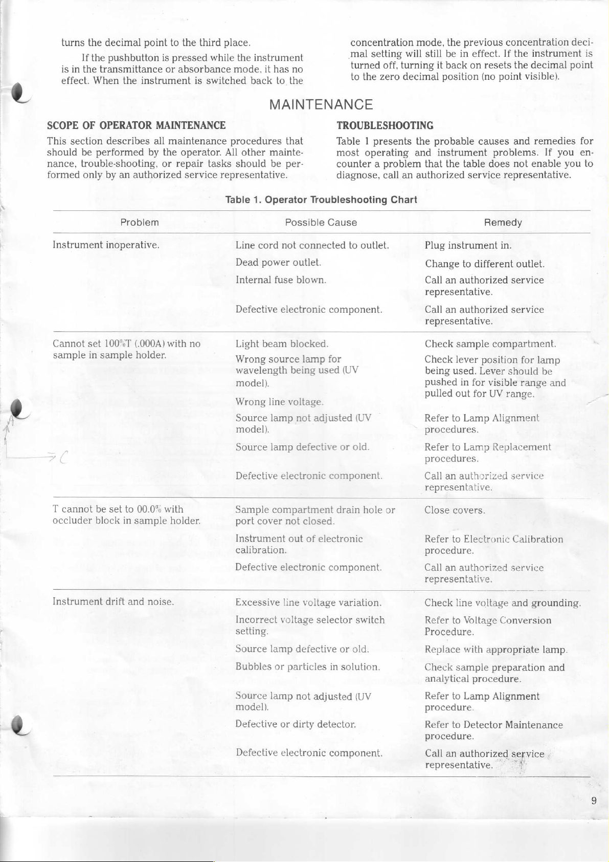
TROUBLESHOOTING
Table 1 presents
most
operating
counter a problem
diagnose,
Cause
to
component.
for
(UV
or
component.
call
Chart
outlet.
(UV
old.
the
probable
and
instrument
that
an
authorized
Plug
Change
Call
representative.
Call
representative.
Check
Check
being
pushed
pulled
Refer
procedures.
Refer
procedures.
Call
representative.
causes
the
table
service
Remedy
instrument
to
different
an
authorized
an
authorized
sample
lever
position
used.
Lever
in
for
out
for
to
Lamp
to
Lamp
an
authorized
and
remedies
problems.
does
not
enable
representative.
in.
outlet.
service
service
compartment.
for
lamp
should
visible
range
UV
range.
Alignment
Replacement
service
If
be
you
and
you
for
en-
to
T
cannot
occluder
Instrument
block
be
set
to
in
drift
00.0%
sample
and
with
holder.
noise.
Sample
port
Instrument
calibration.
Defective
Excessive
Incorrect
setting.
Source
Bubbles
Source
compartment
cover
not
electronic
line
voltage
lamp
or
lamp
model).
Defective
Defective
or
electronic
closed.
out
of
electronic
voltage
selector
defective
particles
not
adjusted
dirty
detector.
drain
hole
component.
variation.
switch
or
old.
in
solution.
(UV
component.
or
Close
covers.
Refer
to
Electronic
procedure.
Call
an
authorized
representative.
Check
Procedure.
Check
Refer
line
Refer
to
Voltage
Replace
analytical
Refer
procedure.
procedure.
Call
with
sample
to
Lamp
to
Detector
an
authorized
voltage
appropriate
preparation
procedure.
Alignment
representative.
Calibration
service
and
grounding.
Conversion
lamp.
Maintenance
service
‘7
and
Page 6

Table
1.
Incorrect
transmittance-to-absorbance
correlation.
Digital
regardless
Incorrect
(Con’t)
display
of
instrument
reading
does
Problem
not
obtained.
change
settings.
Instrument
calibration.
Defective
Instrument
Defective
Stray
Insufficient
Bubbles
Wrong
electronic
electronic
sample
or
wavelength
Possible
out
of
electronic
out
of
calibration.
preparation
sample
particles
setting.
Cause
component.
component.
vapors.
volume.
in
solution.
Remedy
Refer
to
Electronic
procedure.
Call
an
authorized
representative.
Refer
to
Electronic
procedure.
Call
an
authorized
representative.
Prepare
instruments;
ventilation.
Fill
volume.
Check
analytical
Check
wavelength
samples
cuvette
sample
analytical
use
with
procedure.
setting.
Calibration
service
Calibration
service
away
from
proper
greater
preparation
procedure
sample
C
«
and
and
VOLTAGE
1.
Turn
2.
Tilt
voltage
instrument
3.
Refer
cover
CONVERSION
off
and
the
instrument
selector
to
Figure
(mounted
VOLTAGE
unplug
switch,
base.
4.
with
SELECTOR
the
onto
located
Remove
two
SWITCH
instrument.
its
back
on
the
the
voltage
holding
screws).
COVER
for
access
underside
selector
to
the
of
the
switch
Figure
4.
Refer
4.
Location
to
Figure
of
Voltage
5.
Loosen
Selector
the
locking
Switch
nuts
one
turn
each.
ZA
=
LT
Figure
5.
5.
Set
the
(100,
115,
6.
Retighten
7.
Replace
the
two
TUNGSTEN
Models
1.
2.
MV
Turn
off
Tilt
the
housing,
instrument
VOLTAGE
Voltage
=
Selector
voltage
220,
or
the
locking
the
voltage
holding
LAMP
and
and
unplug
instrument
located
base.
DV
SELECTOR
su
001
o
N
\
LOCKING
selector
240
screws.
REPLACEMENT
onto
in
NUTS
Switch
switch
VAC).
nuts.
selector
the
instrument.
its
the
upper
000
Ove
DA
ya
ZÁ
switch
back
SWITCH
ZE
-
at
the
cover
for
access
right
ンク
desired
corner
and
to
the
voltage
tighten
lamp
of
the
10
(=>
Page 7

1.
PUSH
LAMP
MOUNT
2.
PRESS
LOCKING
|
REG
LAMP
DOWN
MOUNT
ON
TAB
INTO
SLOT
(©
IN
WHITE
@
SOCKET
{
Figure
6.
Exterior
3.
Refer
to
Figure
mount
Pull
4.
Grasp
its
lamp
5.
Check
necessary.
6.
Refer
housing
the
7.
Press
the
the
8.
To
inner
of
plate
9.
Insert
plate.
until
tab
the
lamp
the
edges
mount
the
to
Figure
and
socket
the
tab
until
walls
replace
surface
the
housing,
as far
the
Slide
the
(pry
access
lamp
are
aligned
out
new
Avoid
push
at
the
lamp
the
on
both
the
of
to
locking peg
the
peg
is
LAMP
of
Lamp
6.
Lift
gently
mount
through
lamp
touching
7.
Slide
the
rear
mount
front
sides.
access
the
access
and
the
right
peg
snug.
LAMP
ACCESS
MOUNT
Housing
the
with a screwdriver,
plate
tab
with
for
the
plated
of
tab
edge
plate,
press
into
down
TAB
locking
off.
and
the
slots
the
slots.
cleanliness
the
lamp
new
end
the
lamp
down,
of
the
hook
plate
the
plate
as
possible.
the
through
on
Model
peg
raise
in
lamp
of
the
housing.
then
mount
the tab
under
into
eye
on
the
PLATE
MV
out
of
if
the
lamp
the
base.
and
during
installation.
assembly
lamp
pull
is
tight
which
the
tab
place.
the
lamp
lamp
or
DV
the
lamp
necessary).
mount
wipe
mount
forward
at
Slide
mount
so
Pull
the
it
into the
into
on
against
is
on
the
the
top
the
access
tab
if
3.
PULL
IS
TIGHT
Figure
7.
Installation
front
of
lamp
housing
3.
Unscrew
the
tungsten
two
locating
mount
Do
to
not
KNURLED
OUT
the
and
remove
pull
ON
LAMP
AGAINST
of
lamp
housing
cover
remove
lamp
mount.
pins.
Grasp
the
on
the
wires.
THUMBSCREW
MOUNT
WALLS
Lamp
in
base
open.
the
knurled
Slide
the
old
lamp
CAUTION
TAB
ON
BOTH
Model MV
two
thumbscrew
the
lamp
socket
assembly.
LOCATING
LAMP
SO
or
full
and
PINS
MOUNT
SIDES
DV
turns.
Lift
securing
mount
pull
the
MOUNT
the
off
the
lamp
on
the
Model
1.
Turn
2.
Refer
When
the
plate
UVD
off
to
properly
outside
and
and
unplug
Figure
go
of
back
8.
NOTE
installed,
the
lamp
to
the
instrument.
Loosen
access
step
the
the
tip
plate.
5.
clamping
of
the
If
peg
is
not,
screw
visible
remove
on
the
Figure
8.
Tungsten
Mounting
in
SOCKET
Model
CLAMPING
UVD
SCREW
11
Page 8

4.
Check
sary.
5.
With
new
6.Slide
Replace
7.
Perform
this
8.
Close
screw.
the
new lamp
Avoid
touching
the
contact
lamp
into the
the
lamp
the
the
section.
the
lamp
PLATED
CONTACTS
aligned
socket.
mount
knurled
Tungsten
housing
for
cleanliness
the
lamp
during
as
shown
onto
the
thumbscrew.
Lamp
Alignment
cover
and
METAL
CONTACTS
and wipe
installation.
in
Figure
two
locating
procedure
tighten
the
if
neces-
9,
plus
pins.
clamping
the
in
bracket,
slot,
and
provided
8.
Replace
9.Place
10.Be
11.
LAMP
The
tometers
adjustment.
the
located
indicated
sure
Alignment
free
of
Close
the
screw.
ALIGNMENT
lamp
making
the
top
on
the
and
tighten
lamp
behind
on
the
the
lamp
procedure
dust
and
lamp
in
the
SPECTRONIC
is
self-aligning
sure
the
bottom
aligning
mounting
the
knurled
wires
over
the
mounting
label.
is
properly
in
this
fingerprints.
house
cover
(MODEL
post
plate.
plate,
section)
and
UVD
21
MV
and
aligning
is
through
thumbscrew.
the
spade
matching
aligned
and
tighten
ONLY)
and
DV
requires
post
is
in
the
hole
connectors
colors
(see
Lamp
completely
the
clamping
spectropho-
no
special
the
as
LAMP
COLLAR
DEUTERIUM
SØGE
lili
SOCKET
SKE
and
Socket
screw
full
turns
located
11).
in
Figure
the
adjusting
assembly.
on
in
the
and
10,
Figure
10.
Deuterium
Lamp
Mounting
Figure
9.
Model
DEUTERIUM
(MODEL
1.
2.Refer
3.
4.
Alignment
UVD
UVD
Turn
off
to
front
base
open
cover.
Pull the
behind
Unscrew
to
release
bracket
and
Figure
lamp
the
the
the
and
LAMP
ONLY)
unplug
of
the
wires
lamp
knurled
lamp
lift
out
LAMP
of
Tungsten
REPLACEMENT
the
instrument.
10.
Loosen
lamp house
off
the
mounting
thumbscrew,
mounting
the
lamp
MOUNT
Lamp
the
clamping
cover
spade
plate
plate
bracket
Mount
two
connectors
(see
Figure
shown
from
KNURLED
THUMBSCREW—
DEUTERIUM
LAMP
on
lamp
5.
Unscrew
assembly
6.
Place
plate
7.
Place
12
Do
the
not
lamp
or
the
and
the
touch
should
they
the
from
new
secure
lamp
the
will
be
lamp
the
lamp
with
mounting
CAUTION
lamp
be
removed
baked
collar
screws
mounting
assembly
the
lamp
envelope.
before
on.
to
plate.
on
collar
plate
against
Any
remove
the
fingerprints
ignition
the
lamp
mounting
screws.
the
adjusting
of
lamp
the
a
Figure
11.
Deuterium
Lamp
Spade
Connectors
Page 9

DEUTERIUM
HORIZONTAL
TUNGSTEN
VERTICAL
ADJUST
Figure
12.
Lamp
In a Model
be
done
when a lamp
also
be
checked
excess
adjustments.
Tungsten
1.
2.
3.
Turn
Set
Push
noise.
Lamp
the
the
the
range.
4,
Loosen
lamp
house
5.
Using
the
450nm.
6.
Set
the
7.
Close
the
8.
Rotate
transmittance
9.Using
the
the
adjusting
obtain a maximum
By
turning
vertically
out.
By
assembly
tance
readout.
10.
Repeat
imum
necessary
100%T
observable
11.
Close
transmittance
/zero A control
the
screw.
DEUTERIUM
VERTICAL
LAMP—
ADJUST
LAMP—
TUNGSTEN
HORIZONTAL
Alignment
UVM
ADJUST
LAMP—
ADJUST
or
LAMP—
UVD,
Adjustments
lamp
assembly
in
Refer
Alignment
instrument
lamp
power
mirror
the
clamping
cover
wavelength
mode
selector
sample
cases
lever
of
to
Figure
on.
switch
all
screw
two
full
selector,
to
TRANSMITTANCE.
compartment
100%T/zero A control
reading
eccentric
bracket,
the
to
obtain a maximum
turning
horizontally
left
and
right
during
transmittance
lamp
house
around
screws
adjust
transmittance
left
screw,
the
right
to
obtain a maximum
screw
value
this
(step
cover
aligment
is
replaced,
reduced
12
to
TUNGSTEN-VIS.
the
way
on
the
turns
and
set
covers.
to
50%T.
on
the
the
position
reading
move
transmittance
screw,
adjustments
is
obtained.
procedure
8)
to
reset a convenient,
reading.
and
tighten
must
always
and
should
lamp energy
for
location
in
for
the
visible
front
base
of
open
the
cover.
the
wavelength
set a convenient
tungsten
of
the
lamp
move
to
until a max-
the
the
lamp
as
follows:
assembly
the
transmit-
It
may
adjust
clamping
lamp
read-
lamp
or
of
the
to
to
be
the
Deuterium
There
ment.
should
remain
Use
deuterium
When
be
on.
Lamp
are
the
used
safety
lamp
result.
1.
Turn
the
instrument
2.
Set
the
lamp
3.
Ignite
the
button
4.
Set
5.
Loosen
lamp
6.
Using
240nm.
7.
Set
8.
Close
9.
Rotate
transmittance
10.
Using
adjusting
the
house
the
the
the
the
for
mirror
the
mode
the
obtain a maximum
Adjust
12.
By
turning
assembly
tance
readout.
lamp
assembly
transmittance
11.
Repeat
maximum
necessary
100%T
observable
12.
Close
upper
/zero A control
the
screw.
DETECTOR
Low
energy
indicate
1.
Turn
2.
Tilt
MAINTENANCE
or
the
need
off
and
the
instrument
bottom.
Alignment
WARNING
dangerous
lamp house
in
this
procedure
high
cover
voltages
WARNING
glasses.
during
power
deuterium
approximately
lever
clamping
cover
wavelength
selector
sample
100%T/zero A control
reading
eccentric
bracket,
the
screws
vertically
By
readout.
and
transmittance
during
transmittance
lamp
house
the
for
unplug
Do
not
operation.
on.
switch
to
lamp
the
to
by
two
UV
screw
two
full
turns
selector,
to
TRANSMITTANCE.
compartment
around
screws
adjust
the
transmittance
to
the
the
upper
to
obtain a maximum
turning
horizontally
lower
the
the
screw
value
procedure
(Step
reading.
cover
inability
cleaning
to
the
instrument.
onto
its
or
on
on
position
screw,
9) to
and
set
is
removed,
since
look
Eye
within
this
utmost
the
power
directly
damage
DEUTERIUM-UV.
depressing
seconds.
position.
the
and
set
the
cover.
to
50%T.
the
position
value
lower
to
obtain a maximum
the
front
base
open
cover.
wavelength
set a convenient
deuterium
of
the
as
follows:
shown
move
screw,
in
the
transmit-
move
adjustments
is
obtained.
to
It
adjust
reset a convenient,
tighten
100%T
replacing
back
for
the
clamping
or
zero A may
the
detector.
access
equip-
care
must
at
the
may
starter
of
the
lamp
lamp
Figure
lamp
the
until
may
the
to
the
to
to
a
be
13
Page 10

On
digital
DETECTOR
ACCESS
PLATE
following
the
meter
can
and
models
calibration
model
should
(MV)
be
used.
(DV
or
UVD)
procedures
only
the
0%T Calibration
perform
in
the
order
all
three
given.
procedure
of
the
On
Absorbance-to-Transmittance
(Digital
1.
2.Turn
Figure
13.
3.
Remove
by
removing
left.
4.Grasp
through
directly
board
components.
5.
Inspect
necessary,
been
dipped
6.
Insert
grasping
the
aligning
silicon
the
white
tors
located
7.
Replace
holding
Location
the
the
the
below
on
the
the
the
the
detector
plastic
the
screw.
of
detector
the
holding
detector
aligning
the
socket
very
edge
silicon chip
clean
gently
in
methyl
cleaned
detector
mounting
slot
(as
faces
terminal
in
the
instrument.
detector
Detector
access
screw
mounting
slots.
and
to
avoid
for
with a cotton
alcohol.
board
shown
toward
properly
access
Access
plate
(shown
and
lifting
board
If
pliers
only
contact
damaging
dirt
and
or
insert a new
and
inserting
in
Figure
the
light
engages
plate
and
Plate
in
the tab
and
pull
are
used,
the
metal
fingerprints.
swab
which
detector
14).
Be
source
the
secure
Figure
on
the
it
out
pull
mounting
runs
has
it
through
sure
the
and
that
connec-
with
the
13)
or
If
by
Models
Set
the
the
mode
100%T/zero
display
of
the
screwdriver
the
spectrophotometer
calibration
display
Only)
wavelength
selector
A
to
read
39.9.
SENSITIVITY
the
mode
to
pry
adjustment
reads
.399.
dial
to
control,
(If
switch.)
selector
off
the
*
Calibration
to
approximately
TRANSMITTANCE.
set
the
spectrophotometer
necessary,
to
small
control
(shown
change
ABSORBANCE.
access
panel.
in
Figure
340nm.
With
the
plate on
Turn
15)
until
Set
the
setting
Use
a
top
of
the
A
the
Figure
ELECTRONIC
The
does
be
performed
necessary.
.
is
adequate
and
14.
Detector
spectrophotometer
not
require
In
the
following
Before
let
it
warm
Replacement
CALIBRATION
periodic
only
when
for
most
calibrating,
up
for
has
been
calibration.
results
procedures,
applications.
turn
the
at
least
30
factory-calibrated
Calibration
lead
you
to
believe
an
accuracy
spectrophotometer
minutes.
of
+1
and
should
it
is
digit
on
ari.
Figure
15.
Calibration
3.
Switch
should
4.
If
necessary,
reading
disagreement
sorbance
most
a.
In
step
absorbance
calibration
reading
b.Reset
step
c.
Continue
reached
5.
Turn
the
100.0
6.
Turn
the
the
readout.
Location
Adjustments
back
still
read
in
step 3 is
readings,
rapidly
2,
note
difference
the
1.
to
as
mode
with
the
mode
of
Absorbance-to-Transmittance
to
the
transmittance
39.9.
repeat
steps 1 through 3 until the
obtained.
between
the
bring
the
the
amount
and
transmittance
adjustment
by
correct
repeat
in
steps a and b until
step
3.
selector
100%T
/zero A control.
selector
readings
half.
transmittance
to
to
If
the
transmittance
following
of
difference
to
reduce
TRANSMITTANCE
ABSORBANCE
mode.
there
is
procedure
into
agreement.
readings.
the
reading
The
display
correct
substantial
and
between
Turn
the
absorbance
as
agreement
and
and
observe
ab-
will
the
A
in
is
set
14
Page 11

7.
Turn
the
15)
until
(u)
was
clockwise
8.
Repeat
and
100%T = .000A,
9.Turn
SENSITIVITY
10.
With
the
ance
beyond
wavelength
detected
readout.
11.
Switch
calibration
display
01.0
while
correct
0%T
Calibration
1.
Set
the
mode
the
100%T
2.
Install
cover.
3.
Turn
the
16)
until
4.
Remove
A/T
calibration
the
display reads
displayed
steps 1 through 7 to
the
mode
100%T
readout
1.990
energy
back
reads
setting
wavelength
/zero A control,
the
occluder
0%T
the
the
in
step
to
obtain
dial
to
adjustment
you
selector
calibration
display
occluder.
the
then
selector
switch
and
to
/zero A control,
to
overrange
equals
lower
and
the
transmittance
01.0.
(The
turn
the
is
the
(All
Models)
dial
to
in
reads
thus
midpoint
to
set
the
adjustment
.000.
6,
turn
.000
readout.
ensure
proceed
to
ABSORBANCE.
LO.
Observe
.000
2.000A).
than
340nm
increase
(shown
display
adjustment
450nm.
TRANSMITTANCE.
the
display
sample
adjustment
exactly
(shown
If
the
underrange
the
calibration
that
39.9%T = .399A
with
the
increase
(which
If
necessary,
to
the
mode.
in
Figure
will
continue
about % turn.
of
this
range.)
On
digital
to
well
(shown
00.0.
in
control
step
9.
Set
display.
the
absorb-
occurs
turn
decrease
absorbance
Turn
the
15)
until
to
models,
With
read
100.0.
and
close
in
Figure
sign
the
just
the
the
ZERO
the
read
The
set
the
the
Figure
2.While
locate
behind
screwdriver,
pressing
the
exactly
the
CONC.
concentration-factor-check
the
third
vent
turn
the
.100.
slot
screw
FACTOR
shown
until
CHECK
calibration
in
Figure
the
display
button,
screw
17.
With
a
reads
Concentration-Factor-Check
(Digital
1.
Set
the
Models
the
mode
CONC.
Only)
selector
FACTOR
to
CHECK
WARNING
This
inside
Within
the
adjustment
procedure
the
instrument
the
chassis.
involves a screwdriver
chassis.
Do
not
screw.
τὰ
Calibration
ABSORBANCE.
button.
High
insert
the
Press
and
adjustment
voltages
screwdriver
are
fl
“fi
hold
present
beyond
ーー
Figure
17.
Location
Calibration
Adjustment
of
Concentration-Factor-Check
SN
a
fe
~
<P
a
€
Page 12

ACCESSORIES
READOUT
Bausch & Lomb
115V,
220V,
Provides a permanent
obtained
ing a changing
patch
Houston
A;onC:
Digital-to-Analog
For use
Provides
tration
SAMPLE-HANDLING
Liquicell,
An
aqueous
or
DV
can
length
such
General
Cat. No.
For
use
system
(Cat.
UVD
requires
DEVICES
10”
Cat.
No.
39-11-20;
Cat.
No.
39-11-30
during
Strip
cord
Log-linear
Instrument
with
modes.
spectrophotometer.
be
adjusted
is
as
found
Purpose
33-22-44
outside
and
No.
33-22-42)
(Cat.
the
value
Chart
to
connect
model
linear
Cat.
liquid
3mm
for
in
multiple
No.
33-22-43)
Cat.
sample
as
Recorder
recorders
Co.
Converter,
DV
analog
ACCESSORIES
No.
33-22-70
sampling
within
analysis
the
soft
Sample
the
main
sample
and
No.
33-22-29
Strip
Chart
record
analysis.
in
time-rate
requires
the
recorder
NOTE
such
will
permit
or
UVD
output
system
Standard
the
range
of
drink
Compartment,
instrument;
holder.
DV
(Cat.
model,
Recorder,
of
photometric
Also
enzyme
the
to
as
those
direct
Cat.
No.
and
strip
in
absorbance
for
sample
of
high
absorbance
industry.
For
No.
33-22-41).
the
sample
optical
rail
useful
for
procedures.
Cat.
No.
the
instrument.
available
recording
33-22-46
chart
and
use
with
volume
3-25ml.
comes
use
with
For
compartment
assembly.
values
monitor-
39-20-11
from
in
T,
recorder.
concen-
model
MV
of
5ml
Cell
path-
samples,
with
lens
the
MV
use with
For
Use
with
General
SEMI-MICRO/FLOW-THRU
CAT.
NO.
33-22-33
Required
flow-thru
THERMO-REGULATED
CAT.
Water-jacketed
thermo-block
perature
being
environment.
For
CUVETTE
Required
SAMPLE
For
SPACER,
For
SPACER,
For
Replacement
Cat.
Selected,
SPECTRONIC*
SPECTRONIC
performance
ratory
loading a cuvette
radiant
cal
certified
ever
for
cuvettes
NO.
33-20-14
between 5 and
made
on
Use
with
ADAPTER,
for
COMPARTMENT
test
tubes
CAT.
use
with
2mm
CAT.
use
with
5mm
No.
33-17-75
10mm
quality
energy,
alignment.
by
Bausch & Lomb
applicable.
using
45
to
multiple
maintains
sample
Main
Instrument
short
cuvettes,
or
cuvettes
NO.
33-17-98
pathlength
NO.
33-17-97
pathlength
Test
Tube
pathlength,
STANDARDS,
standards
quickly,
control
to
check
photometric
The
standards
CAT.
Purpose
10mm
48mm
CUVETTE
sample
10mm
55C
requiring a temperature-controlled
COVER,
up
Cuvettes
let
accurately,
program.
0%T,
Sample
CUVETTE
pathlength
tall.
HOLDER,
holder
square
while
Sample
NO.
33-22-08
45
to
to
102mm
cuvettes,
cuvettes,
optical
CAT.
you
check
as
They
wavelength
accuracy
are
individually
and
traceable
Compartment
HOLDER,
semi-micro
with
three-position
cuvettes
measurements
Compartment
48mm
CAT.
tall.
NO.
33-22-07
tall.
45mm
45mm
glass,
NO.
33-31-50
spectrophotometer
part
make
/linearity,
tall.
tall.
box
of
of
normal
it
as
accuracy,
tested
to
NBS
at
12.
easy
and
or
tem-
are
labo-
as
stray
opti-
and
wher-
16
Page 13

APPENDIX
A
TRANSMITTANCE
All
SPECTRONIC
relative
transmittance.
calibration,
Furthermore,
with
the
to
unknown
logarithmic
on
standard
drawn
known
concentration
transmittance
amount
stray
greater
transmittance
set
A
the
sensitivity
100%T,
samples
standard
paper
logarithmic
solutions
through
samples
ABSORBANCE
Usually,
direct
abc.
absorbance
conversion
in
known
is
the
correlation
Results
tables
absorbance
standards
drawn
through
operator
in
values
curve.
The
concentration
mined
tion
unknown.
instrument
to
values
ator
values
sion
ance
and
in
concentration
and
standard
studies and
by
locating
value
which
To
eliminate T to A calculations,
provides
absorbance:
Model
may
The
the
absorbance.
Absorbance
MV
corresponding
simply
to
construct a standard
digital
of
transmittance
mode
is
used,
results
pathlength
curve
for
MODE
21
of
light
The
radiant
very
low
mode
and
the
are
curve
by
axis
on
these
may
value
of
the
MODE
to
percent
by
or
may
be
on
rectilinear
these
on
corresponds
has
an
read
models
the
for
standards
Results
by
Beer’s
are
as
described
measurements
reaction
CHOOSING
spectrophotometers
transmitted,
transmittance
energy
concentrations
in
the
is
used,
results
obtained
may
plotting
vs.
the
the
linear
points.
then
be
which
unknown
by
conversion
corresponds
desires
concentration
transmittance
use
of
the
formula A =
plotted
points
of
unknowns
the
standard
absorbance
to
percent
the
absorbance
offer
to
absorbance.
reference
and
in
absorbance
Law, A =
known,
systems
mode
tests,
transmittance
the
reagent
for
standard
as
percent
be
constructed
the
percent
concentration
axis.
The
concentration
determined
on
the
results
by
can
transmittance-absorbance
against
the
graph
to
construct a standard
curve
to
the
of
transmittance
scale
transmittance.
scale
curve
as
precise
blank
unknowns
abc,
or
by
above.
are
which
measure
yielding
and
can
results
is
useful
filter
be
measured
mode.
blank
solutions
transmittance.
on
transmittance
of
The
best
by
locating
to
the
standard
in
Beer’s
paper.
can
absorbance
each
described
electronic
When
is
used
may
if
construction
useful
do
curves.
absorbance
Law, A =
be
converted
-logyT.
concentration
The
best
then
be
the
concentra-
model
marked
The
and
use
the
to
set
are
obtained
be
related
the
absorptivity
for
not
obey
A
the
in
for
studies.
When
is
used
and
semi-
known
line
is
of
un-
the
percent
for
to
Results
of
line
deter-
of
the
of
the
values
with
oper-
these
above.
conver-
absorb-
.000A,
to
of
a
kinetic
Beer’s
READOUT
Law
and
MODE
therefore
CONCENTRATION
The
digital
tometer
tion
mode,
ing a standard
converts
multiplying
standard
can
be
been
conditions
interest,
Furthermore,
the
standard
increases
When
instrument
blank,
alone,
introduce
concentration, c =
It
because
the
concentration
display
Operating
models
offer a more
which
results
the
curve
used
only
verified
include
cuvette
curve
with
using
in
the
set
000C.
should
the
is
not
actually
this
factor
to
read
Instructions
curve.
in
absorbance
(1/ab).
if
for
pathlength,
the
concentration
concentration).
the
absorbance
(A
be
used.)
1/ab
the
CONCENTRATION-FACTOR-CHECK
To
verify
that
operating
reagent batches
tion-factor-check
tion
mode
the
CONC.
factor.
standard
new
press
factor
of
conditions.
used
choose,
then
FACTOR
may
instrument.
given
reagent
the
on
A
change
the
standard
to
switch
be
FACTOR
solutions
the
set
however,
CHECK
used
or
has
been
on
batch
CONC.
digital
in
the
It is
recommended
the
concentration
to
the
button
to
Standards
feature
have
non-linear
MODE
of
the
SPECTRONIC
convenient
eliminates
absorbance
the
the
wavelength,
has a positive
concentration
true
factor
l/abx
the
The
value
Note
that
linearity
test
conditions
mode
reagent
Using
which
A.
NOTE
necessary
is
introduced
adjust
control
concentration
for
detailed
conditions
from
day
as
follows:
set
up
with
CHECK
the
are
FACTOR
curve
to
concentration
button
digital
used
for
or
when
setting
CHECK
display.
factor
indicates a change
due
set the
pressed,
set
the
pre-recorded
should
standard
21
readout,
necessity
instrument
to
concentration
the
of
the
concentration
and
analytical
mode
slope
and,
blank,
known
converts
to
know
into
is
used
of
the
by
the
concentration
standard
used.
can
be
(i.e.,
mode,
using
not
standard
absorbance
the 1 ab
the
instrument
to
the
standard.
instructions.)
FEATURE
do
not
to
day,
use
the
After
the
standard
and
display.
the
to
variation
that a standard
mode.
blank
mode.
the
be
run
read
Every
same
up
button
The
to
CONC.
for
solutions,
and
test
the
000A
With
factor
verification.
plots.
spectropho-
concentra-
for
construct-
electronically
units
by
slope
of
the
mode
curve
has
These
procedure.
used
absorbance
first
the
just
set
vary
concentra-
concentra-
(such
instrument).
and
in
in
operator
ADJUST
test
range
solutions,
the
record
time
operating
always
the
only
set
the
reagent
reagent
factor
when
digital
(See
between
press
new
as
for
note
the
slope
may
or
000C,
CONC.
of
if
to
the
the
be
knob
into the
a
А-1
Page 14

APPENDIX
B
The
digital
information
absorbance,
ALL
MODES
INTERPRETING
readout
on a model
beyond
and
(TRANSMITTANCE,
displays
concentration.
Display
HEHE
Pi
THE
DV
or
UVD
of
percent
The
following
ABSORBANCE,
example
DIGITAL
provides
transmittance,
useful
informa-
CONCENTRATION).
Overrange
Underrange
READOUT
tion
fully
instrument.
ON
A
on
readout
utilize
Interpretation
This
segments
the
Real
combinations
being
These
segments
“o”
“overrange”
not valid
interpretation
the
is
what
of
decimal
readings
off
and
are
in
and
“u”
when
MODEL
capabilities
the
display
the
four
point
locations
are
made
of
these
on.
the
permitted
the
far
left
using
the
and
“underrange.”
either
DV
is
provided
of
would
7-bar
characters
were
from
28
bars
combinations
character.
upper
half
of
them
or
UVD
so
you
your
digital
look
like
and
lit
at
once.
different
and 3 dots
of
The
small
only
mean
Readings
is
displayed.
can
if
model
all
all
are
more
€
TRANSMITTANCE
Validity
Status
Underrange
EL
MODE
Display
τα)
D
example
|
One
Zero
-1%T
beyond
-0.6%T
or
In-range
than
all
left
Rapidly
occur
the
Interpretation
For
zero
-1%T
offset
readings
one
in
this
segments
place.)
changing
for
two
POWER
calibration
%T
the
will
switch
is
made
display
not
being
may
location.
off,
nonsense
or
three
on
reasons,
readable
“locks
change
have
(Zero
since
seconds
or
off.
the
as
up,”
the
reading
no
digit
other
is
shown
this
is
the
displays
region
shown.
and a further
may
after
turning
just
Around
observed.
by
far
below
eg
-0.1%T
Page 15

9
TRANSMITTANCE
Validity
Status
In-range
MODE
(Con’t)
Display
E]
|
E
|
5
example
[].
H,
=
e
ο
[]
E
Interpretation
When
between
is
straightforward.
the
transmittance
n
zero
mode.
and
This
199.9%T,
is
the
usable
the
reading
range
in
Overrange
ABSORBANCE
Validity
We
Status
ER
MODE
=]
l |
l
Display
e
©
|
O
9
>
9
example
| 2 |
]
|
|
205.8%T
E
220%T
or
more
-007A
-.010А
ог
beyond
When a %T
left
character
it
flags
invalid
220%T
light
will
Interpretation
Negative
manner
approach a setting
direction.
-.010A;
reading
reading
does
an
overrange
readings.
the
readout
not
further
absorbances
shown
additional
thereafter.
The
so
readout
of
not
At
some
“locks
the
of
light
increase
199.9
is
become a 2.
condition
reading
up”;
are
displayed
user
can
.000A
from
“locks
would
exceeded,
Instead,
indicating
around
additional
the
reading.
in
easily
this
up"
at
around
not
change
the
the
the
Page 16

ABSORBANCE
Validity
Status
πα
MODE
(Con’t)
Display
example
000
MEE
πας
[2496
EEE
Interpretation
When
absorbance
and
This
mode.
1.999A,
is
the
the
usable
readings
reading
range
are
between
is
straightforward.
in
the
absorbance
zero
2000
|
Overrange
E]
[]
[|
ο
Eh
CONCENTRATION
The
examples
apply
almost
ing
the
fact that 1 is
place.
An
important
mode
you
can
MODE
from
without
the
difference
move
the
absorbance
change
only
or
omit
to
concentration
digit
possible
is
that
in
the
decimal
mode
the
|
H
2.008A
=.
discussion
too,
includ-
in
the
left-hand
concentration
point.
When
exceeded,
overrange
readings.
the
in
levels.
an
absorbance
readout
response
the
left
condition
At
some
“locks
to
further
reading
character
indicating
reading
up”
and
decrease
of
1.999
flags
invalid
around
will
not
in
is
the
2.200A,
change
light
B-3
 Loading...