

Page 1
SECTION
1
DESCRIPTION
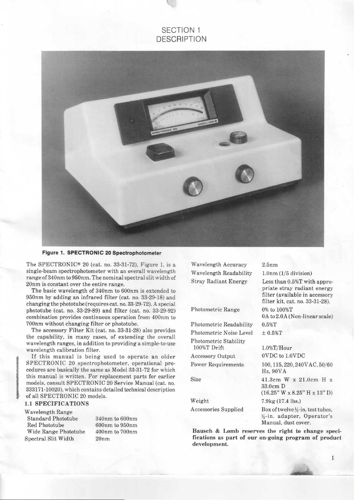
Figure
The
SPECTRONIC®
single-beam
range
of
20nm
is
The
950nm
changing
phototube
combination
700nm
The accessory
the
capability,
wavelength
wavelength
If
this
SPECTRONIC
cedures
this
manual
models,
333171-10020),
of
all
SPECTRONIC
1.1
SPECIFICATIONS
Wavelength
Standard
Red
Phototube
Wide
Range
Spectral
1.
SPECTRONIC
spectrophotometer
340nm
constant
basic
by
without
are
consult
Slit
to
over
wavelength
adding
the
phototube
(cat.
no.
provides
changing
Filter
in
ranges,
calibration
manual
20
basically
is
written.
SPECTRONIC
which
Range
Phototube
Phototube
Width
20
20
(cat.
no.
with
950nm.
an
The
nominal
the
entire
range.
of
340nm
infrared
(requires
33-29-89)
continuous
Kit
many
in
addition
filter.
is
being
spectrophotometer,
the
contains
20
filter
and
filter
(cat.
cases,
used
same
For
replacement
detailed
models.
340nm
600nm
400nm
20nm
cat.
or
no.
of
to
providing a simple-to-use
as
Model
20
Spectrophotometer
33-31-72),
an
to
600nm
(cat.
no.
filter
operation
phototube.
33-31-28)
extending
to
Service
to
600nm
to
950nm
to
700nm
Figure
overall
spectral
33-29-72). A special
operate
33-31-72
technical
wavelength
slit
is
extended
no.
33-29-18)
(cat.
no.
33-29-92)
from
400nm
also
provides
the
an
operational
for
parts
for
Manual
description
1,
isa
width
and
overall
older
pro-
which
earlier
(cat.
no.
of
to
to
Wavelength
Wavelength
Stray
Photometric
Photometric
Photometric
Photometric
100%T
Accessory
Power
Size
Weight
Accessories
Bausch & Lomb
fications
development.
Accuracy
Readability
Radiant
Range
Readability
Noise
Stability
Drift
Output
Requirements
Supplied
as
part
Energy
Level
reserves
of
our
on-going
41.3cm
33.0cm
(16.25” W x
7.9kg
Box
X-in.
Manual,
2.5nm
1.0nm
(1/5
division)
Less
than
0.5%T
priate stray
filter
(available
filter
kit,
cat.
0%
to
100%T
0A
to2.0A
0.5%T
+
0.5%T
1.0%T/Hour
OVDC
100, 115,
Hz,
the
(Non-linear
to
1.0VDC
220,
90VA
W x 21.0cm H x
D
(17.4
Ibs.)
of
twelve
adapter,
dust
right
program
with
radiant
in
accessory
no.
33-31-28).
240V
AC,
8.25” H x
4-in.
test
Operator's
cover.
to
change
of
appro-
energy
scale)
50/60
13”
D)
tubes,
speci-
product
Page 2
1.2
OPERATING
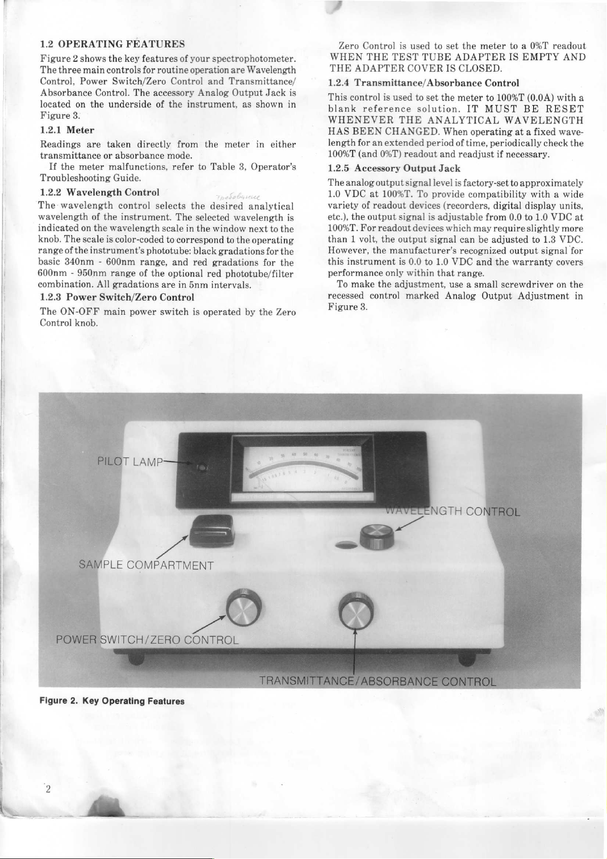
Figure 2 shows
The
three
main
Control,
Absorbance
located
Figure
1.2.1
Readings
transmittance
If
Troubleshooting
1.2.2
The
wavelength
indicated
knob.
range
basic
600nm - 950nm
combination.
1.2.3
The
Control
Power
Control.
on
the
3.
Meter
are
the
meter
Wavelength
wavelength
of
on
the
The
scale
of
the
instrument’s
340nm - 600nm
All
Power
ON-OFF
Switch/Zero
knob.
FEATURES
the
key
features
controls
underside
taken
or
malfunctions,
the
wavelength
is
range
main
for
Switch/Zero
The
directly
absorbance
Guide.
Control
control
instrument.
color-coded
phototube:
range,
of
gradations
power
of
your
spectrophotometer.
routine operation
Control
accessory
of
the
mode.
refer
selects
The
scale
to
correspond
and
the
optional
are
Control
switch
and
Analog
instrument,
from
the
to
Table
the
desired
selected
in
the
window
black
red
gradations
red
in
5nm
intervals.
is
operated
are
Wavelength
Transmittance/
Output
meter
wavelength
to
gradations
phototube/filter
Jack
as
shown
in
3,
Operator's
:
analytical
next
the
operating
for
by the
either
to
the
for
the
the
Zero
is
in
is
Zero
Control
WHEN
THE
1.2.4
This
blank
THE
ADAPTER
Transmittance/Absorbance
control
reference
WHENEVER
HAS
BEEN
length
for
100%T
(and
1.2.5
Accessory
The
analog
1.0
VDC
variety
etc.),
100%T.
than 1 volt,
However,
this
performance
recessed
Figure
of
the
output
For
instrument
To
make
3.
is
TEST
COVER
is
used
THE
CHANGED.
an
extended
0%T)
readout
Output
output
signal
at
100%T.
readout
signal
readout
the
output
the
manufacturer's
is
only
within
the
adjustment,
control
marked
used
to
set
the
meter
TUBE
to
solution.
set
ADAPTER
IS
CLOSED.
the
meter
IT
Control
to
MUST
ANALYTICAL
When
operating
period
of
time,
periodically
and
readjust
Jack
level
is
factory-set
To
provide
devices (recorders,
is
devices
signal
0.0
to
1.0
that
compatibility
adjustable
which
may
can
be
recognized
VDC
and
range.
use a small
Analog
from
Output
to a 0%T
IS
EMPTY
100%T
(0.04)
BE
WAVELENGTH
at a fixed
if
necessary.
to
approximately
digital
require
adjusted
display
0.0
to
slightly
output
the
warranty
screwdriver
Adjustment
readout
AND
with
RESET
wave-
check
the
with a wide
units,
1.0
VDC
at
more
to
1.3
VDC.
signal
for
covers
on
the
in
a
PLE
COMPARTMENT
SWITCH/ZERO
CONTROL
Figure
2.
Key
Operating
Features
Page 3
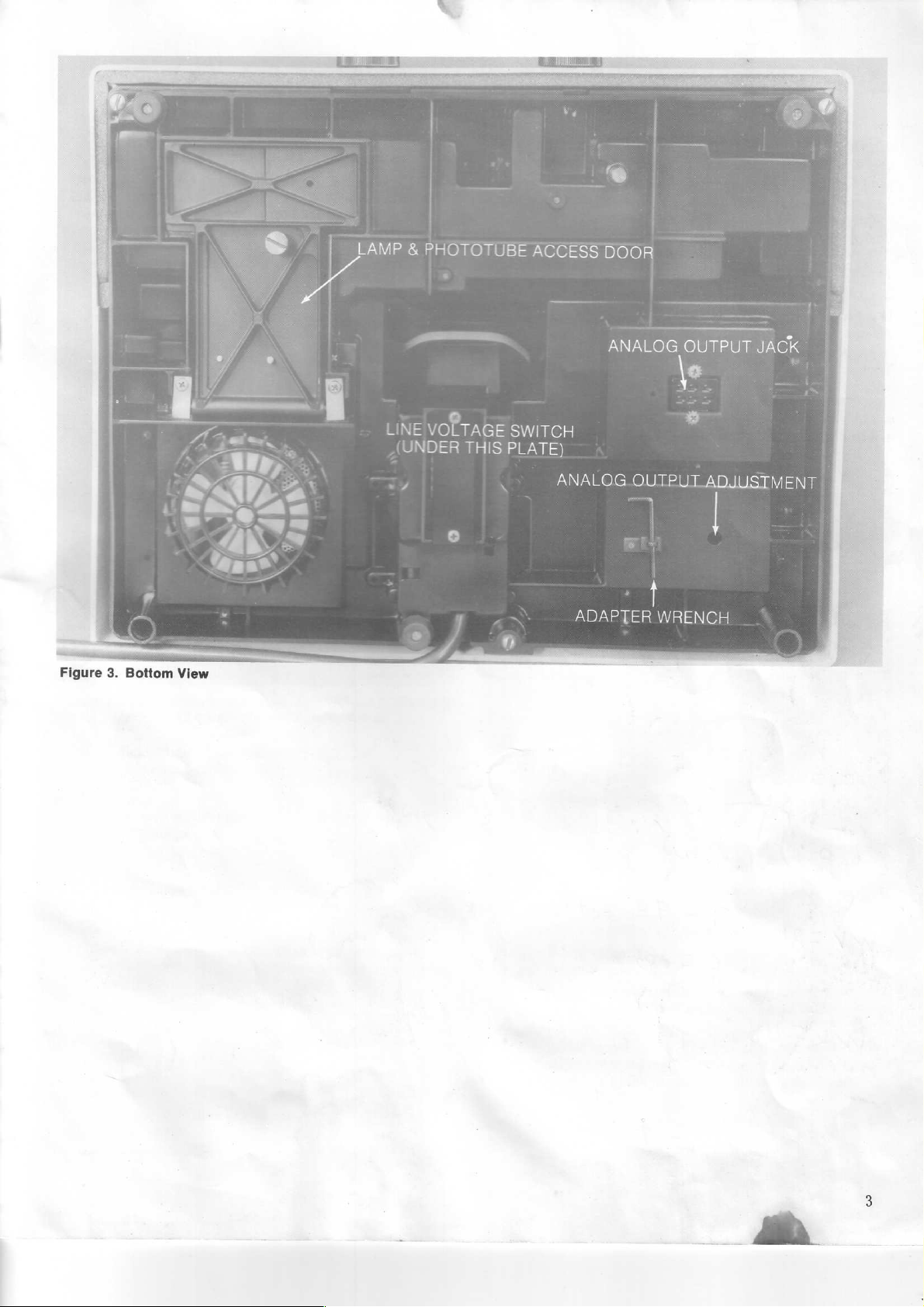
LAMP
&
PHOTOTUBE
ACCESS
DOOR
ANALOG
VOLTAGE
DER
Figure
3.
Bottom
View
THIS
SWITCH
PLATE)
ANALOG
ADAPTER
OUTPUT
OUTPUT
le
ADJUSTMENT
WRENCH
J
a
Oe
ee
AO
Page 4

2.1
ENVIRONMENT
The
SPECTRONIC
as
far
as
possible
or
any
electrical
The
instrument
dust,
corrosive
In
addition,
hinder
2.2
The
former
is
Rochester,
voltage
instrument
accessible
the
a.
b.
air
flow
LINE
VOLTAGE
spectrophotometer
for
operation
set
to
operate
New
selection
to
by
instrument
UNPLUG
Tilt
Remove
located
up
THE
the
the
in
3.
c.
Set
the
switch
d.
Replace
required.
e.
If
the
converting
changing
1.
Remove
expose
meter.
2.
Replace
the
0.7
labels
supplied
20
spectrophotometer
from
any
strong
apparatus
should
gases,
there
under
be
and
should
and
generating
installed
severe
be
around
CONVERSION
contains a multiple-tap
on
100, 115,
at
115
VAC
York,
USA.
switch,
the
removing a cover
(see
shown
available
Figure
3).
CAUTION
INSTRUMENT
unit
and
set
on
two
the
lower
to
cover
to
the
Line
control
fuse
holder
the
ampere
screws
1.5
center
the
proper
plate
220
Voltage
knobs,
at
ampere
SLO-BLO
to
the
holding
and
or
magnetic
vibrations.
no
obstructions
the
220,
when
If
conversion
in
line
plate
BEFORE
its
back
of
the
voltage
change
240
VAC
Selection
sample
the
rear
SLO-BLO
250 V fuse
fuse
block
should
or
high
in
an
area
instrument.
240
VAC,
it
leaves
Figure
4,
voltage.
located
panel.
the
switch
base,
shown
position.
the
line
operation,
Switch:
adapter
of
the
250 V fuse
supplied;
and
INSTALLATION
be
placed
electric
frequency
the
is
necessary,
will
The
on
PROCEEDING
and
spectrophoto-
to
fields,
fields.
that
is
free
which
power
50/60
factory
adapt
switch
the
bottom
cover
plate
in
Figure
cord
plug
after
cover
with
apply
the serial
SECTION
of
might
trans-
Hz.
It
in
the
the
is
of
if
to
2
3.
Figure
number
Replace
ment
4.
Line
access
plate
cover,
is
now
Voltage
ready
plate
on
the
knobs
Selection
shown
bottom
and
for
operation
in
of
sample
Switch
Figure
the
instrument.
adapter.
at
220
(located
3)
or
The
240
instru-
VAC.
under
Page 5
SECTION
OPERATING
3
PROCEDURES
The
instrument
the
factory
operate
Section
3.1
SETUP
To
help
your
a.
Install
b.
Select
ο.
Turn
warm-up.
3.1.1
In
addition
supplied
available.
shown
screw
wrench
3).
Test
Y-in.
of
in
at
100,
2.2.
ensure
spectrophotometer:
reguired
and
on
Glassware
to
with
The
in
Table
on
the
clipped
Table
Glassware
Tubes:
dia.,
12,
cat.
is
set
to
Rochester,
220,
or
240
uncomplicated
adapter
install
appropriate phototube
Power
optical
no.
Switch/Zero
Selection
the
standard
the
instrument,
sample
inner
1.
to
To
i.
adapter
change
wall
the
bottom
Glassware
glass,
33-17-80.
CAUTION
operate
New
York,
V.
If
adjustment
and
and
%-in.
several
must
adapters,
of
the
of
box
at
115
VAC
USA
adjustment
select
sample
Control
Sampling
test
tube and
types
match
loosen
adapter
the
instrument
and
Adapters
Adapter
33-31-27
(Supplied
instrument)
when
it
leaves
and
can
be
is
required,
P
and
operation
holder.
filter.
for a 15-minute
Options
%-in.
adapter
of
glassware
the
glassware,
the
small
using
the
adapter
(see
Figure
Cat.
No
with
set
see
are
to
of
as
set
To
TURN
.
Tilt
.
Loosen
Figure
.
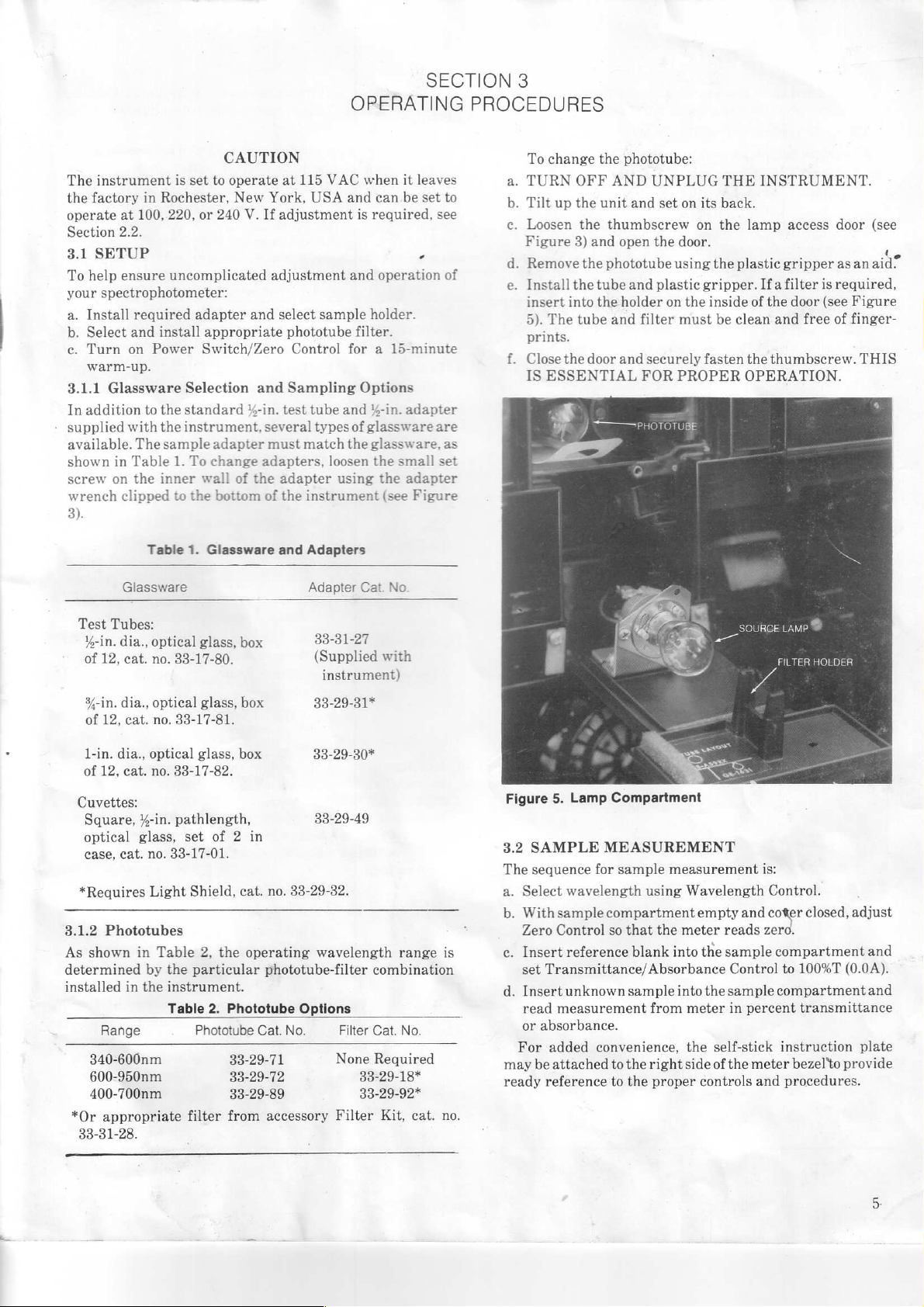
Remove
e.
Install
insert
5).
prints.
Close
IS
change
The
up
the
OFF
the
the
3)
the
the
into
tube
door
the
unit
thumbscrew
and
phototube
tube
the
ESSENTIAL
Y < РНОТОТУВЕ
phototube:
AND
UNPLUG
and
open
the
and
holder
and
filter
and
securely
FOR
set
on
on
door.
using
plastic
on
the
must
PROPER
SK
a
©
THE
its
back.
the
lamp
the
plastic
gripper.
inside
be
clean
fasten
the
OPERATION.
SOURCE
INSTRUMENT.
access
gripper
Ifa
filter
of
the
door
and
free
thumbscrew.
LAMP
*
FILTER
door
as
is
required,
(see
of
HOLDER
(see
4
an
aid”
Figure
finger-
THIS
%-in.
dia.,
of
12,
cat.
1-in. dia.,
of
12,
cat.
Cuvettes:
Square,
optical
case,
cat.
*Requires
3.1.2
Phototubes
As
shown
determined
installed
*Or
in
Range
340-600nm
600-950nm
400-700nm
appropriate
33-31-28.
optical
no.
33-17-81.
optical
no.
33-17-82.
%-in.
pathlength,
glass,
no.
33-17-01.
Light
in
Table
by the
the
instrument.
Table
glass,
box
glass,
box
set
of 2 in
Shield,
particular
filter
cat.
2,
the
2.
Phototube
Phototube
33-29-71
33-29-72
33-29-89
from accessory
33-29-31*
33-29-30*
33-29-49
no.
33-29-32.
operating
phototube-filter
Cat.
wavelength
Options
No.
combination
Filter
Cat.
None
33-29-18*
33-29-92*
Filter
range
No.
Required
Kit,
cat.
is
no.
Figure
5.
Lamp
Compartment
3.2
SAMPLE
The
seguence
a.
Select
With
b.
may
ready
samplecompartment
Zero
Control
İnsert
set
Transmittance/ A bsorbance
.
Insert
read
measurement
or
absorbance.
For
added
be
attached
reference
MEASUREMENT
for
sample
wavelength
so
that
reference
unknown
sample
convenience,
to
the
to
the
using
the
blank
from
right
proper
measurement
Wavelength
empty
meter
reads
into
the
sample
Control
into
the
sample
meter
in
the
self-stick
side
of
the
controls
is:
Control.
and
coter
zero.
compartment
compartment
percent
meter
and
closed,
adjust
to
100%T
(0.0A).
transmittance
instruction
bezel*to
procedures.
provide
and
and
plate
Page 6

Correct laboratory
are
necessary
a.
All
solutions
b.
All
sample
с.
For
greater
with
adapter,
Problem
1.
Instrument
does
not
work.
2.
Meter
does
zero.
3.
Meter
reading
drifts
for
successful
must
holders
accuracy,
cat.
a.
b.
с.
d.
e.
not
a.
b.
c.
d.
e.
a.
b.
c.
d.
e.
f.
g.
NOTE
procedures
use
be
free
must
be
use
square
no.
33-29-49.
Possible
Power
line
not
connected
outlet.
Dead
let.
Source
burned
Phototube
fective.
Defective
tronic
nent.
Sample
partment
not
closed.
Occluder
ing.
Lamp
door
not
closed.
Phototube
fective.
Defective
tronic
nent.
Poor
sampling
technique.
Fumes
sample.
Excessive
voltage
tion.
Wrong
line
age
setting.
Source
fective.
Phototube
fective.
Meter
tive.
and
of
of
bubbles.
at
least
Cause
cord
power
lamp
out.
de-
elec-
compo-
com-
cover
bind-
access
tightly
de-
elec-
compo-
from
line
varia-
volt-
lamp
de-
defec-
analytical
your
spectrophotometer.
half
full.
cuvettes,
to
cat.
Table
Plug
cord.
out-
Replace
lamp.
Replace
quired.
Refer
manual
center.
Check
tion.
Replace
quired.
Refer
manual
center.
Eliminate
or
particles
tion.
Remove
immediately
analysis.
Check
grounding.
Reset
Selection
de-
Replace
lamp.
Replace
quired.
Refer
manual
center.
techniques
i
no.
33-17-01,
3.
Operators
Remedy
in
power
with
as
re-
to
service
or
service
occluder
as
re-
to
service
or
service
bubbles
in
sample
voltage
Line
Voltage
Switch.
with
as
re-
to
service
or
service
line
new
ac-
solu-
after
and
new
d.
For
optimum
ensure
mark
During
e
an
occasional
causes
Troubleshooting
Problem
4.
Cannot
100%T
5.
Readings
not
repeatable
even
though
meter
reading
is
zero
100%T
is
set
correctly.
performance
that
the
on
the
adapter.
extended
of
meter
Guide
set
(0.0A).
are
and
control
index
operation
check
drift
are
Possible
.
Defective
tronic
nent.
.
Occluder
.
Sample
not
serted
dapter.
.
Improper
installed.
.
Source
weak.
.
Wrong
age
.
Phototube
.
Error
length
tion.
.
Defective
tronic
nent.
.
Loose
cess
.
Loose
holder
.
Poor
technigue.
.
Test
tion
ing.
.
Meter
with
test
mark
on
the
at a fixed
for
100%T
listed
in
Cause
elec-
compo-
closed.
holder
fully
in-
into
a-
filter
Lamp
line
volt-
setting.
weak.
in
wave-
calibra-
elec-
compo-
lamp
ac-
door.
sample
adapter.
analytical
tube
posi-
not
repeat-
sticking.
tube
sample
tube aligns with
wavelength,
meter
Table
drift.
3.
Refer
manual
center.
Install
sample
Remedy
to
service
or
test
compart-
ment.
Insert
fully.
Remove
or
filter.
Replace
lamp.
Reset
Selection
Replace
quired.
Check
Refer
manual
center.
Tighten
screw.
Tighten
Clean
dirty
remove
ete.
Always
fiducial
actly
place
tube
into
Tap
sible
with
Line
Switch.
as
calibration.
to
service
or
thumb-
set
or
replace
test
bubbles,
position
line
the
when
is
inserted
adapter.
lightly
correction.
holders,
the
make
Possible
service
tube
in
change
new
Voltage
re-
service
screw.
tubes;
in
ex-
same
test
for
pos-
Page 7

SECTION
MAINTENANCE
4
Because
functional
routine
ment
phototube
checks
as
well
If
the
and
beyond
qualified
to
Section
of
the
design
customer
of
the
6.5V,
(Table
for
wavelength
as
change
replacement
Service
the
instrument,
the
Manual.
scope
dealer
4.6,
or
Service
SPECTRONIC
(cat.
no.
333171-10020)
qualified
4.1
a.
b.
c.
d.
e.
f.
4.2
To
procedure
4.3
Under
to
perform
LAMP
TURN
Tilt
Loosen
the
Using
REPLACEMENT
OFF & UNPLUG
up
the
the
door.
finger
mounting
clockwise
To
install
the
socket
Clean
the
lamp,
IS
ESSENTIAL
PHOTOTUBE
replace
the
in
WAVELENGTH
normal
unit
thumbscrew
pressure,
flange
and
the
and
phototube,
Section
operating
spectrophotometer
indefinitely.
or
other
one
of
a.
Cobalt
b.
Didymium
abuse,
three
Solution
If
the
wavelength
methods:
filter
33-31-28).
SPECTRONIC
and
its
tested
maintenance
2.75A
source
2).
The
operator
calibration
the
operating
parts
are
needed, a complete
For
the
protection
instrument
of
this
section
Bausch & Lomb
Procedure.
NOTE
20
Spectrophotometer
is
available
electronic
and
set
on
on
press
(see
Figure
remove.
new
lamp,
use
rotate
lamp
close
the
door,
FOR
PROPER
REPLACEMENT
refer
8.1.2
of
this
CALIBRATION
condition
should
instrument
Check.
from
retain
performance
the
20
and
field-proven
has
been
lamp
(cat.
can
and
line
voltage.
repair
should
service
servicing.
THE
INSTRUMENT.
its
back.
the
lamp
the
lamp
6).
Rotate
LIGHT
clockwise
and
tighten
OPERATION.
to
the
phototube
manual.
the
its
wavelength
is
subjected
accessory
spectrophotometer’s
reliability,
reduced
also
photometric
of
to
access
socket
the
finger
until
to
no.
33-33-85)
perform
accuracy,
list
is
both
the
or
maintenance
be
performed
personnel.
Service
those
technically
door
and
toward
lamp
pressure
secure.
securely.
replace-
and
routine
found
operator
Refer
Manual
open
the
counter-
THIS
oT
CHECK
SPECTRONIC
accuracy
to a severe
may
be
Filter
checked
Kit
(cat.
shock
no.
in
by
on
20
by
c.
Wavelength
dards
(cat.
An
explanation
Instructions
Standards
are
SPECTRONIC
Canada
4.3.1
First
a.
b.
only.
Cobalt
prepare a stock
Ina
1-liter
Add
slowly
chloric
distilled
In a 1-liter
acid
chloride
acid.
Make
to
obtain
To
perform
a.
Turn
power
b.
Set
Wavelength
c.
Withsample
Zero
Control
d.
Insert
sample
Control
e.
Replace
glassware
compartment
at
distilled
chloride
Figure
6.
Lamp
Accuracy
no.
33-31-50).
on
use
of
found
Standards
Solution
volumetric
and
(ACS
water
to
volumetric
(ACS
grade).
to
volume
chloride
cobalt
ON.
compartment
until
100%T.
stock
solution.
Replacement
Test
of
the
cobalt
the
didymium
in
the
user's
are
Check
cobalt
solution
flask,
with
caution,
grade).
obtain
Mix
1%
hydrochloric
flask,
Dissolve
with
1%
stock
solution.
solution check:
Allow
15-minute
Control
at
500
empty
meter
reads
filled
with
and
set
water
with
Read
from
SPECTRONIC
solution
filter
manual
available
as
place
200
10
ml
and
place
in
hydrochloric
check
and
SPECTRONIC
for
each
in
the
follows:
ml
distilled
concentrated
make
to
volume
acid
22-23
the
1%
hydrochloric
acid
follows.
accessory.
U.S.A.
solution.
gm
solution
warm-up.
nm.
and
cover
closed,
zero.
distilled
Transmittance/Absorbance
glassware
%T
on
water
containing
meter.
into
Stan-
and
water.
hydro-
with
cobalt
adjust
the
cobalt
uk
Page 8
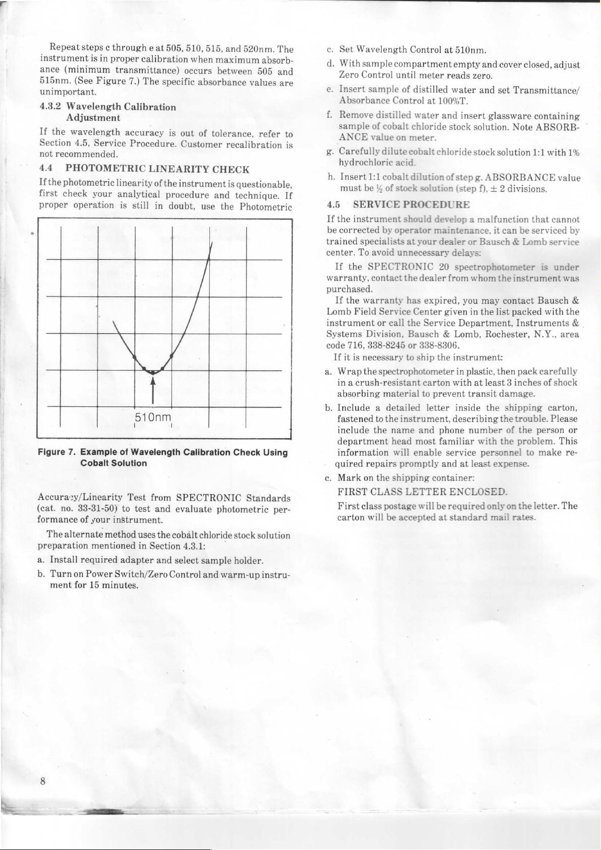
Repeat
instrument
ance
515nm.
unimportant.
4.3.2
If
Section
not
44
If
the
first
proper
Figure
Accura:y/Linearity
(cat.
formance
The
preparation
a.
Install
b.
Turn
ment
steps
is
(minimum
(See
Figure
Wavelength
Adjustment
the
wavelength
4.5,
Service
recommended.
PHOTOMETRIC
photometric
check
your
operation
no.
alternate
7.
Example
Cobalt
33-31-50)
of
your
mentioned
required
on
Power
for
15
in
minutes.
c
through
proper
e
calibration
transmittance)
7.)
The
Calibration
accuracy
Procedure.
LINEARITY
linearity
analytical
is
still
of
in
N
|
510nm
of
Wavelength
Solution
Test
from
to
test
and
instrument.
method
uses
in
Section
adapter
Switch/Zero
at
505,
510,
when
occurs
specific
is
out
Customer
the
instrument
procedure
doubt,
7
Calibration
SPECTRONIC
evaluate
the
cobält
4.3.1:
and
select
Control
515,
and
maximum
between
absorbance
of
tolerance,
recalibration
CHECK
is
and
use
the
Check
photometric
chloride
sample
and
stock
holder.
warm-up
520nm.
questionable,
technique.
Photometric
absorb-
505
values
refer
The
and
are
to
is
If
Using
Standards
per-
solution
instru-
c.
d.
e.
f.
g.
h.
4.5
If
the
be
trained
center.
If
warranty,
purchased.
If
Lomb
instrument
Systems
code
If
a.
Wrap
in a crush-resistant
absorbing
b.
Include a detailed
fastened
include
department
information
quired
c.
Mark
FIRST
First
carton
Set
Wavelength
Withsample
Zero
Control
Insert
sample
Absorbance
Remove
sample
ANCE
Carefully
hydrochloric
Insert
must
corrected
it
distilled
of
value
1:1
be % of
SERVICE
instrument
specialists
To
avoid
the
SPECTRONIC
contact
the
warranty
Field
Service
or
Division,
716,
338-8245
is
necessary
the
spectrophotometer
to
the
repairs
on
the
CLASS
class
will
cobalt
dilute
cobalt
by
call
material
the
postage
be
Control
compartment
until
meter
of
distilled
Control
on
acid.
stock
operator
name
head
will
shipping
at
100%T.
water
chloride
meter.
cobalt
chloride
dilution
solution
PROCEDURE
should
unnecessary
instrument,
promptly
accepted
develop a malfunction
maintenance,
at
your
dealer
the
dealer
has
expired,
Center
the
Service
Bausch & Lomb,
or
338-8306.
to
ship
the
carton
to
prevent
letter
and
most
familiar
enable
container:
LETTER
will
be
at
at
510nm.
empty
and
reads
zero.
water
and
and
insert
glassware
stock
solution.
stock
solution
of
step
g.
ABSORBANCE
(step
f), + 2
it
or
Bausch & Lomb
delays:
20
spectrophotometer
from
whom
the
you
may
given
in
the
list
Department,
Rochester,
instrument:
in
plastic,
with
inside
describing
phone
service
and
at
ENCLOSED.
required
standard
then
at
least 3 inches
transit
the
number
with
personnel
least
expense.
only
mail
cover
closed,
set
Transmittance/
containing
Note
ABSORB-
1:1
divisions.
that
can
be
serviced
is
instrument
contact
damage.
shipping
the
of
the
on
Bausch
packed
Instruments
N.Y., area
pack
carefully
of
trouble.
the
person
problem.
to
make
the
letter.
rates.
adjust
with
1%
value
cannot
by
service
under
was
with
the
shock
carton,
Please
or
This
re-
The
&
&
Page 9

The
following
SPECTRONIC
SPECTRONIC
a.
reliable
0%T,
wavelength
metric
adapter,
33-29-49.
Filter
SPECTRONIC
Filter
energy/2nd
10-in.
Includes 1 roll
Manual.
10-in.
Strip-Chart
Includes 1 roll
Manual.
Patch
Recorder
TRONIC
DR-37
no.
33-30-92.
accessories
20
spectrophotometer:
Standards,
way
to
test
and
accuracy,
accuracy
cat. no.
Adapter,
and
33-31-26,
cat.
Standards.
Kit,
cat. no.
order
filters, 1 didymium
Strip-Chart
of
chart
of
chart
Cord,
cat.
no.
(cat.
no.
33-11-20
20
spectrophotometer.
Digital
Readout
are
available
evaluate
stray
optical
and
no.
33-31-26.
33-31-28.
Recorder,
paper, 4 ink
Recorder,
paper, 4 ink
33-26-74.
Accessory,
for
use
cat.
no.
33-31-50.
instrument
radiant
alignment;
cuvette
performance:
energy,
requires
holder,
Required
Includes 4 stray
filter.
115
V,
cat.
cartridges,
220
V,
cat.
no.
cartridges,
Connects
or
39-11-30)
115
V.
to
50-60
SECTION
ACCESSORIES
with your
Quick,
photo-
filter
cat. no.
for
use
with
radiant
no.
39-11-20.
Operator’s
39-11-30.
Operator’s
Strip-Chart
the
SPEC-
Hz,
cat.
5
h.
DR-837
no.
Patch
Readout
meter.
Step-down
to
.
SPECTRONIC
Industrial
tions.
Alloys,
332905-10030;
10030.
332902-10030.
.
Water
grouping
wastewater
n.
Accurate
Digital
33-30-93.
Cord,
115
V.
Aluminum
Ring
Technology
Readout
cat. no.
Accessory
transformer,
20
Service
Methods
Alloys,
cat.
no.
332904-10030;
Gold
binder
of
EPA-recommended
analyses.
Water
Testing
Accessory,
33-26-71.
to
SPECTRONIC
cat.
Manual,
Manual.
cat.
and
Gold
to
hold
Manual,
Manual,
Connects
no.
33-32-97.
cat.
Purchase
no.
Copper
Alloys,
any
or
cat.
methods
cat.
230
V,
50-60
DR-87
20
spectrophoto-
Converts
no.
333171-10020.
in
separate
332903-10030;
Alloys,
cat.
no.
all
sections,
no.
331015-10030.
for
water
no.
330935-10030.
Hz,
cat.
Digital
220
V
sec-
Steel
cat.
no.
332906-
cat.
no.
A
and
 Loading...