

Page 1
0-1
06/00
Ident. No. 822-085
Operating manual
High Voltage Testing Sets
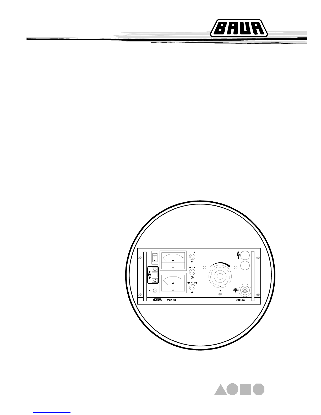
PGK 70 HB
PGK 70 - 2,5 HB
PGK 110 HB
PGK 150 HB
PGK 260 HB
BAUR Prüf- und Messtechnik GmbH
Raiffeisenstrasse 8, A-6832 Sulz / Austria
Tel +43 / 55 22 / 49 41-0
Fax +43 / 55 22 / 49 4 13
e-mail: [email protected]
internet: http://www.baur.at
Page 2

0-2
Page 3
0-3
For fast finding of important information the corresponding text
passages are marked with symbols (symbols not stated here are
self-explaining).
More and special information concerning the respective subject are
available from BAUR.
Important unit information!
In any case, read carefully!
Important information text.
Observe
info signs!
☞
Guide to this Operating Instruction
Copyright
© BAUR Prüf- und Messtechnik GmbH,
A-6832 Sulz / Austria
All rights reserved.
No part of this publication may be reproduced, transmitted, stored in
a data processin gsystem or translated into another language
without the written permission of BAUR / Sulz, Austria.
In the interest of our customers we reserve the rights for
modifications due to technical progress. Illustrations, descriptions
and delivery content are therefore not binding.
© Copyright by BAUR
This manual contains all information necessary for the correct
handling and use of the high voltage testing set PGK 70 HB,
PGK 70 - 2,5 HB, PGK 1 10 HB, PGK 150 HB und PGK 260 HB.
Before using the surge voltage generator , please read carfully this
Operating Instruction.
Preface
If you have any question, please contact directly
BAUR Prüf- und Messtechnik GmbH, Raiffeisenstrasse 8
A-6832 Sulz / Austria
or refer to your nearest BAUR representative.
Please read now and
avoid damage and injury later!
- The PGK 70 HB, PGK 70 - 2,5 HB, PGK 1 10 HB, PGK 150 HB
und PGK 260 HB is built in accordance with today's state of
engineering and is safe to operate. Individual components and
the finished unit are inspected continually by our qualified staff
within the framework of our Quality Assurance Provisions. Each
unit is subjected to thorough testing prior to shipment.
Guide to this Operating Instruction, Copyright, Preface
Subject to modification!
Safety Precautions
Tel +43 / 55 22 / 49 41-0
Fax +43 / 55 22 / 49 41 3
Page 4
0-4
- It is imperative to every person who is involved with the
installation, start-up, operation and maintenance to have read and
understood the complete Operating Instruction.
- It is the responsibility of the customer to ensur that only
authorized persons may be allowed to use the high voltage
testing sets.
The user
- is qualivied and properly instructed and has the necessary
experience.
- knows the relevant standards, accident prevention rules and
operating conditions.
- is able to carry out the necessary operations and is aware of
the possible dangers involved.
- must immediately inform his superior about any conditions of
the unit that could affect safety .
The high voltage testing sets are to be applied exclusively for
voltage proof testing of electrical equipment.
The local safety and accident prevention requirements are
always applicable to the operation of the PGK 70 HB, PGK
70 - 2,5 HB, PGK 110 HB, PGK 150 HB and PGK 260 HB unit.
At the customer's written request we undertake to repair or replace
at our discretion and as quickly as possible all parts that become
faulty or useless as the demonstrable results of poor material, faulty
design or defective execution.
We bear the costs for repairs and replaced parts, exclusive
transportation of the goods, packing and insurance.
The 12 month warranty time st arts with delivery .
We shall bear the costs of any faulty parts requiring replacement,
but not the costs of transport to us an back to the customer , not the
costs of packing and insurance! We shall not be liable for any
damage resulting from normal wear and tear, improper handling, nonobservance of Operating Instruction and safety requirements. We
shall also refuse to accept any liability if the customer carries out
repairs or changes to the unit himself or has others carry out them!
The warranty does not cover damage in transit, batteries, fuses and
any readjustments in accordance with the Operating Instruction!
We draw attention in addition to the "General Terms of Sales and
Delivery" of.
Warranty
Safety Precautions, Warranty
Safety Precautions, Continued
Only authorized personnel!
Use the PGK 70 HB, PGK 70 - 2,5 HB,
PGK 110 HB, PGK 150 HB and
PGK 260 HB unit as directed!
12 month warranty time
BAUR Prüf- und Messtechnik GmbH, Raiffeisenstrasse 8
A-6832 Sulz / Austria
Page 5

0-5
Contents
1. Product Information ...................................................................... 1-1
Overview ...................................................................................... 1-1
Design and function ..................................................................... 1-2
Display and operating elements................................................... 1- 4
T echnical data ............................................................................. 1-5
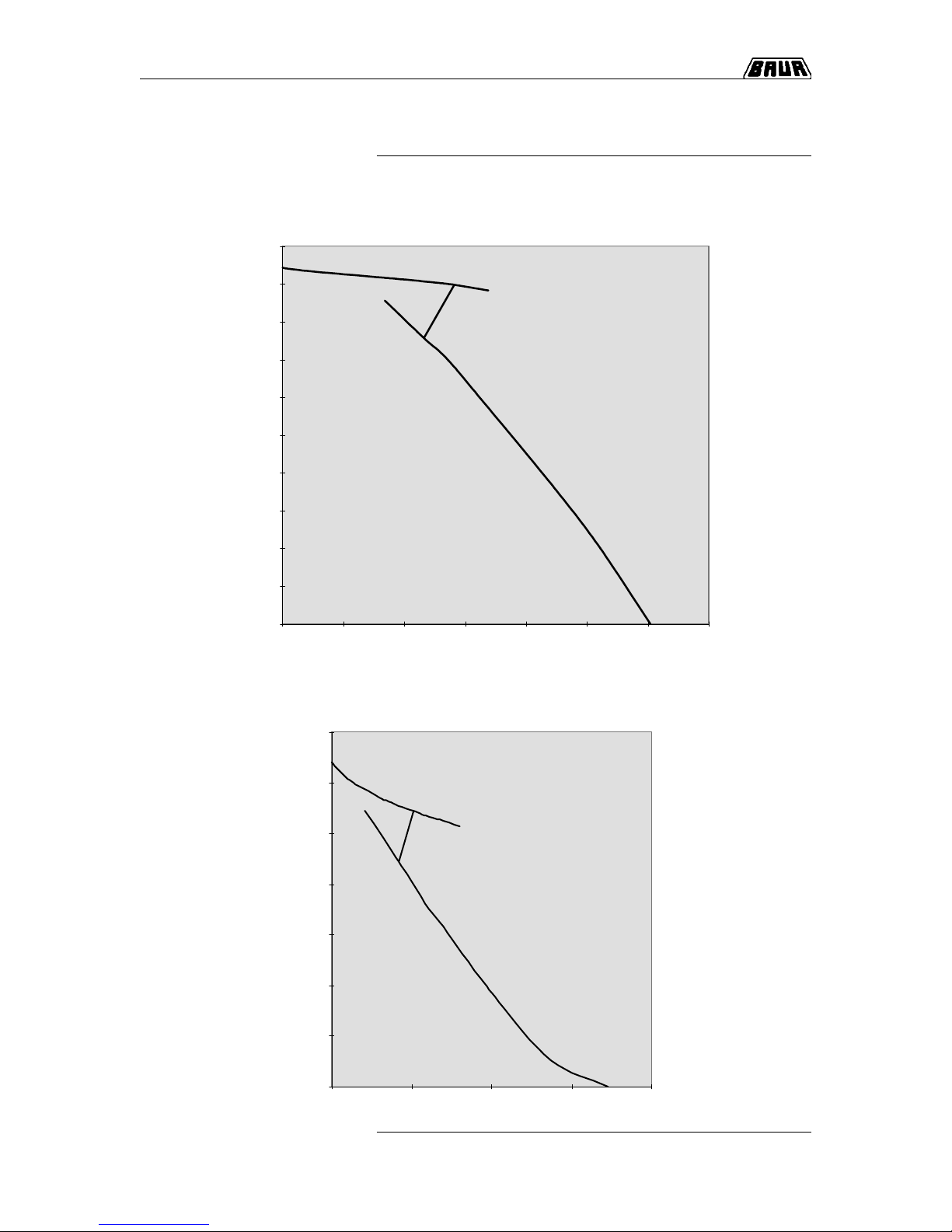
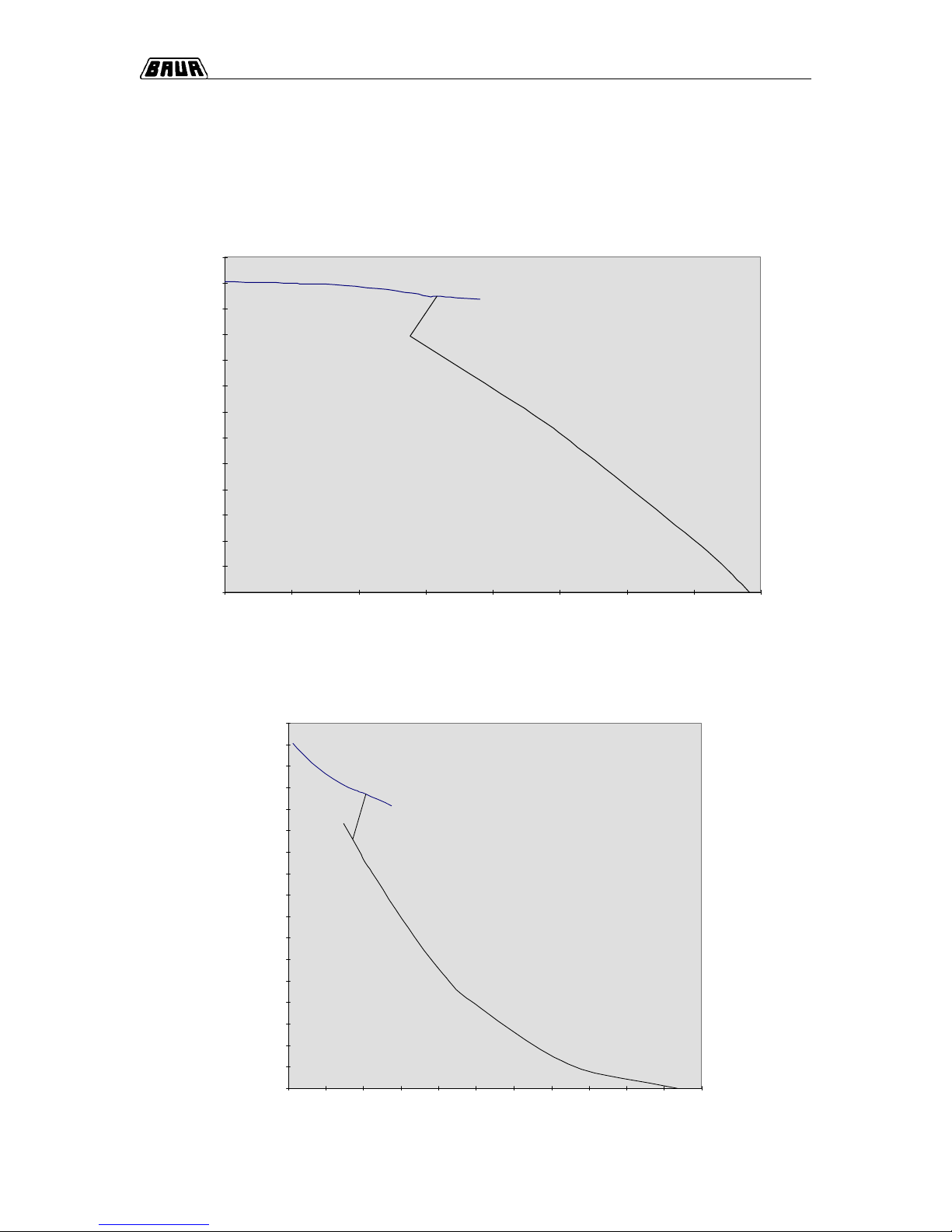
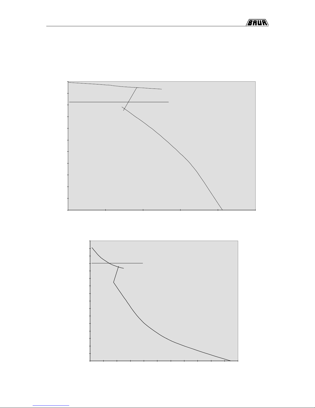
PGK Load curves ........................................................................ 1-6
2. Packing and Shipping .................................................................. 2-1
Damage during transport ............................................................. 2-1
3. Placing into operation .................................................................. 3-1
Overview ...................................................................................... 3-1
Connect to earth.......................................................................... 3- 2
Switch on .................................................................................... 3 - 2
Switch off..................................................................................... 3-4
EMERGENCY -OFF ..................................................................... 3-4
Change operating mode............................................................... 3-5
4. Servicing / Maintenance............................................................... 4-1
Overview ...................................................................................... 4-1
General ....................................................................................... 4-2
Fuse............................................................................................ 4-2
Contents
Page 6

0-6
Contents, Continued
Contents
5. Options, Accessories and Ordering Information ..................... 5-1
Overview ...................................................................................... 5-1
Options ....................................................................................... 5-2
Accessories ................................................................................ 5-3
Ordering information .................................................................... 5-5
Page 7
1-1
1. Product Information
Subject Page
Design and function 1-2
Display and operating elements 1-4
Technical data 1-5
PGK Load curves 1-6
1. Product-Information
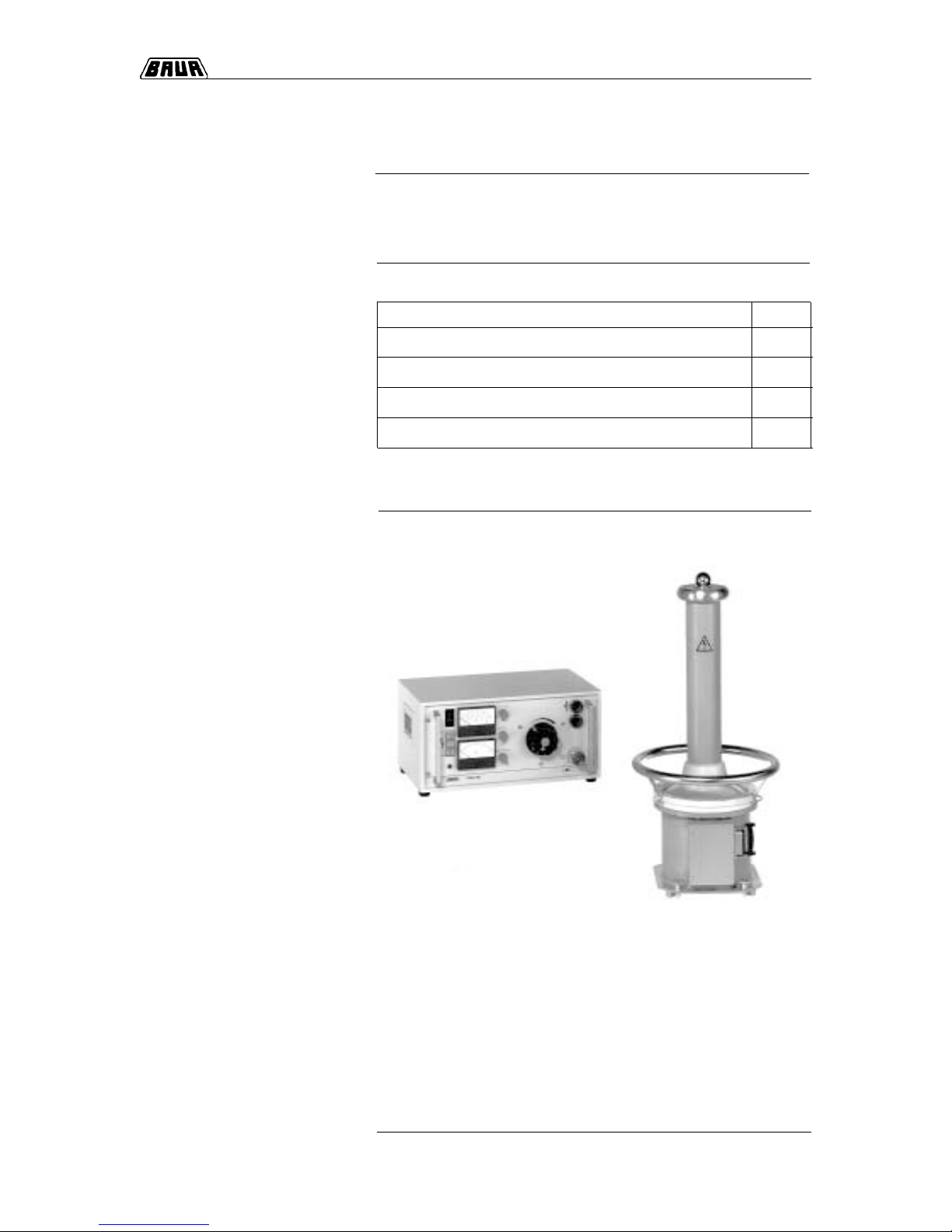
Overview
This section contains all necessary information about the High
Voltage Testing Sets PGK HB.
This section contains the following subjects:
General view
PGK 70 HB
Page 8

1-2
1. Product Information
Design and Function:
With the PGK 70 - 2,5 HB, PGK 1 10 HB, PGK 150 HB and the
PGK 260 the corona protection hood is used as oil expansion tank
(conservator) and may not be removed or damaged. With the
PGK 70 HB an air cushion in the housing (tube) works as a
compressible volume for absorbing the oil expansion. That’s why
the H.V . unit may only be stored, shipped and operated vertically.
Generation of high voltage is carried out by a H.V. transformer
supplied by an variable transformer. During D.C. operation a halfwave rectifier is connected after the H.V. transformer. By turning the
half-wave rectifier the polarity of the output voltage can be changed.
The capacity of the test object acts as smoothing capacitor. During
A.C. operation, a damping resistor is connected to the H.V . circuit
instead of the half-wave rectifier (with PGK 260 HB: option - not
included)
The H.V. units of the PGK HB instruments are equipped with a
potential grading ring which can also be used as carrying ring. The
instruments may be not operated without this potential grading ring.
The PGK HB instruments are designed as two-part High V oltage
Testing Sets.
• Operating unit with all indicating/operating elements, with power
supply and safety devices.
• High Voltage unit as oil-filled housing with High Voltage trans-
former with the choice of a rectifier bar for half-wave rectification
or a resistance bar as a damping resistor.
Design
Depending on the load by the test object and the voltage set, the
PGK HB instruments are operating in one of the two operating
ranges Continuous Operation and Short-time Operation.
Continuous operation:
Within this operating range, from no-load to nominal rating up to
cut off load the instrument can be loaded continuously .
Short-time operation:
Within this operating range from cut off load to short circuit the
instrument switches current-limiting lamps into the primary circuit of
the H.V . transformer in order to reduce the thermal load of the
instrument. Additionally, as a protection against overload the
overcurrent protection switch (5) with its thermal and magnetic
tripping characteristic is tripped after a specific period terminating
operation. The time until tripping depends on load and takes from
seconds (during short-circuit) to hours (at maximum load).
☞
Operating ranges
High Voltage generation
☞
Page 9

1-3
1. Product Information
The mA-meter is connected into the H.V. circuit on earth side.
D.C. operation:
The mA-meter shows the arithmethic mean value of the output
current.
A.C. operation: (option with PGK 260 HB)
The rectification value of the A.C. is measured by the instrument.
However, the display shows the appropriate rms value. That’s why
there can be deviations of the displayed value from the true rms
value if the measured current is not sinusoidle. During no-load the
mA-meter shows the current which flows via the self-capacitance of
the H.V. transformer. Must be considered during measurements on
test objects.
The kV-meter is connected to a tapping of the H.V. winding and is
current-compensated. The compensation is balancing the voltage
drop at the internal resistance of the test instrument.
D.C. operation:
The kV-meter shows the peak value of the output volt age. If the
self-capacitance of the test object is very low it is possible that the
insulation current of the test object results in a high ripple. In this
case, note that the displayed value and the arithmetic mean value
of the test voltage can be clearly different.
Display during A.C. operation:
(option with PGK 260 HB)
As with the mA-meter the kV-meter also measures the rectification
value and displays the rms value.
kV - meter
mA - meter
Page 10
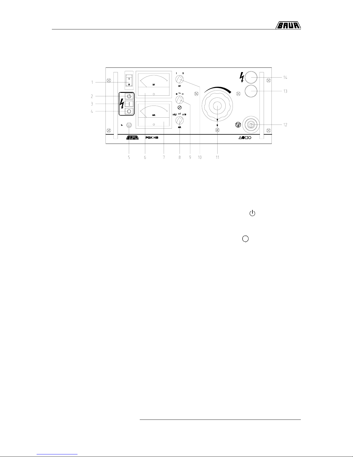
1-4
1. Product Information
1
Mains switch
as overcurrent safety switch with thermal
tripping
2
Pushbutton „Ready to switch on“
( )
3
Pushbutton „High Voltage On“
( I ) with pilot lamp
(clearing of H.V.)
4
Pushbutton „High Voltage Off“
( )
5
Overcurrent safety switch
with thermal and magnetic
tripping
6
Voltmeter
for display of output voltage in kV
7
Amperemeter
for display of output current in mA
8
Measuring range switch
for amperemeter
9
Selector switch for operating mode
(+ / ~ / -)
10
Measuring range switch
for voltmeter
11
Variable transformer
for setting the output voltage
12
Lockabel Emergency off momentary contact switch
13
Indicator lamp, green
14
Indicator lamp, red
Display and operating elements
Page 11
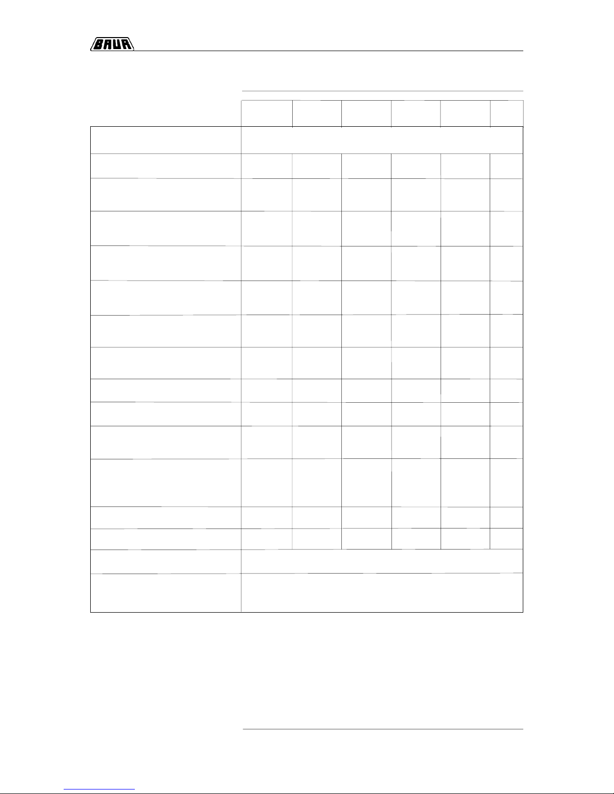
1-5
1. Product Information
PGK PGK 70 PGK PGK PGK unit
70 HB - 2,5 HB 1 10 HB 150 HB 260 HB
Mains voltage see type plate V ~
Mains frequency 45 to 60 45 to 60 45 to 60 45 to 60 45 to 60 Hz
Power consumption at
nominal working point 640 3200 1380 1380 2600 VA
Max. power consumption
(in short-circuit operation) 1200 6500 2650 2650 5000 VA
Power output at nominal
working point AC/DC 330/190 2750/1260 1260/495 990/530 1665/1000 VA/W
Max. output voltage
ACeff/DC in no-load 56/78 56/78 94/126 1 10/160 185/260 kV
Output voltage ACeff/DC
at nominal working point 47/66 55/62 90/108 1 10/137 185/250 kV
Max. output current
ACeff/DC at short-circuit 20/12 117/84 30/17 23/20 20/20 mA
Accuracy of kV-meter 2,5 2,5 2,5 2,5 2,5 %
Accuracy of mA-meter 2,5 2,5 2,5 2,5 2,5 %
Dimensions of operating unit 502 x 502x 502 x 502 x 502 x
housing (W x H x D) 242 x 290 242 x 290 242 x 290 242 x 290 242 x 290 mm
Dimensions
of H.V. unit
(height / diameter) 810/385 1 130/455 1130/455 1450/455 2050/1270 mm
Weight of operating unit 13,5 22 17 17 19 kg
Weight of H.V. unit 27 93 75 85 260 kg
Relative humidity not condensing
Ambient temperature working: 0...+45° C
storage: -20...+60° C
Technical Data
Page 12
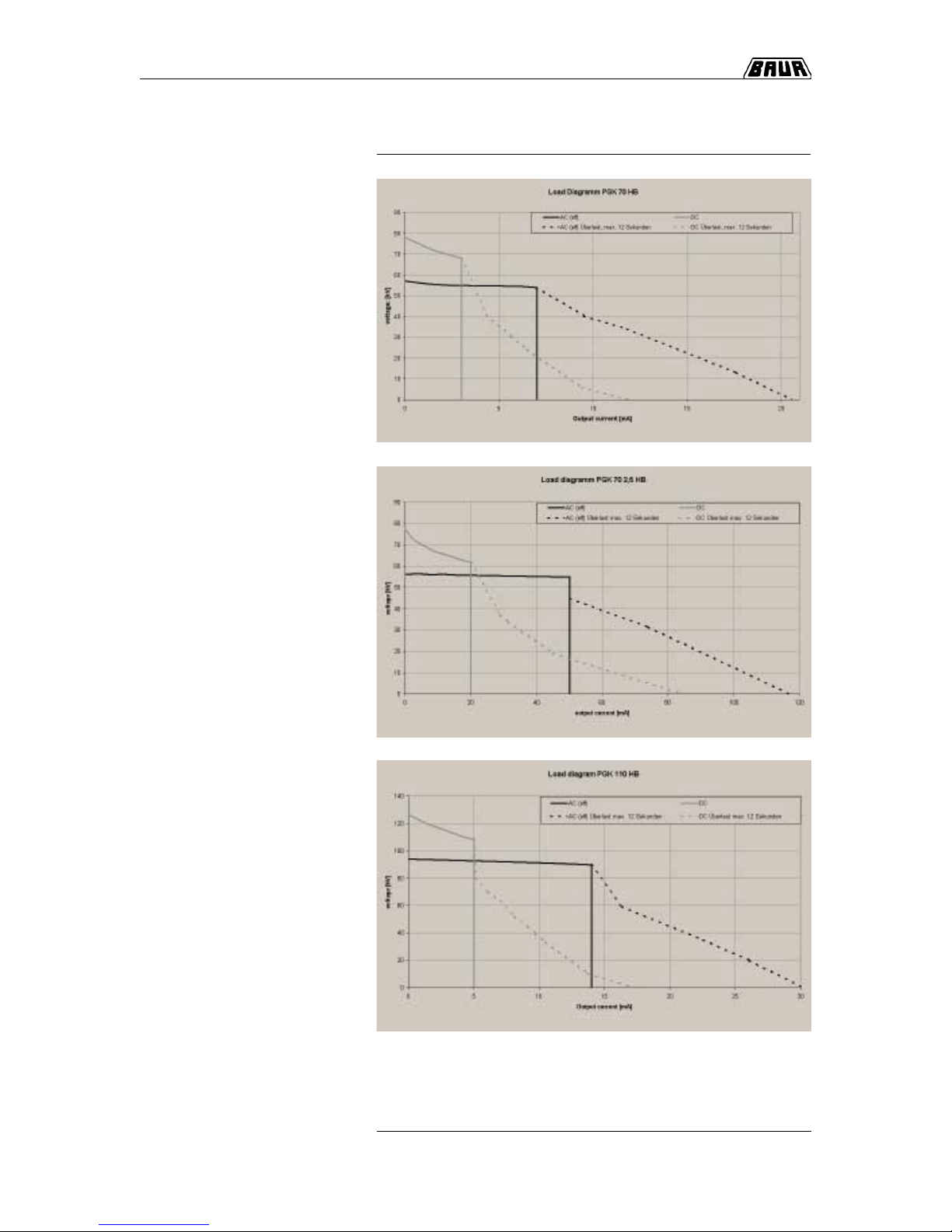
1-6
1. Product Information
PGK output load curves
Page 13
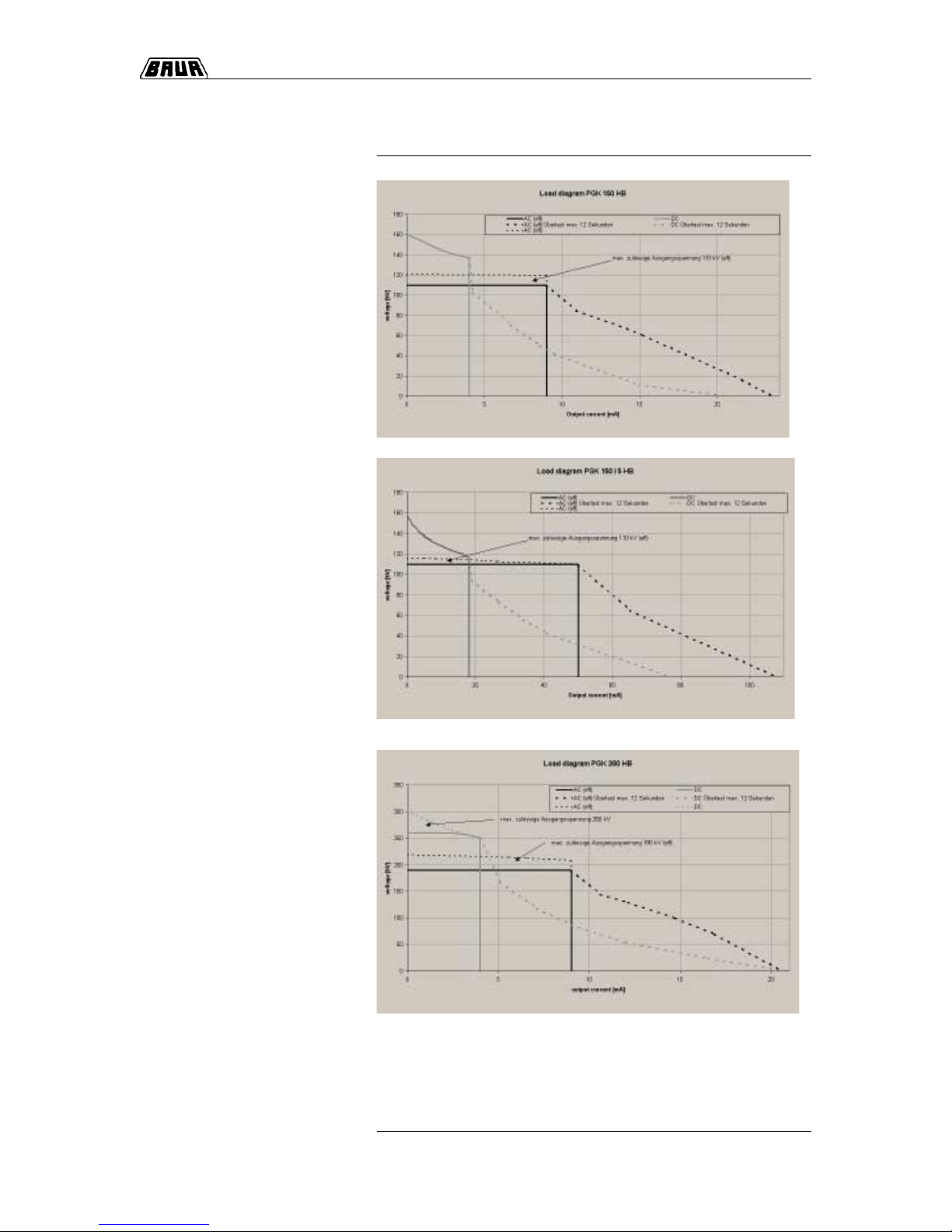
1-7
1. Product Information
Page 14
1-8
1. Product Information
Load curve PGK 110 HB AC
1-8
Load curve PGK 110 HB DC
0
10
20
30
40
50
60
70
80
90
100
0 5 10 15 20 25 30 35
I / kV
U / kV
0
20
40
60
80
100
120
140
0 5 10 15 20
I / mA
U / kV
mA
Page 15
1-9
1. Product Information
Load curve PGK 150 HB AC
LLoad curve PGK 150 HB DC
0
10
20
30
40
50
60
70
80
90
100
110
120
130
0 3 6 9 12 15 18 21 24
I / mA
U / kV
0
10
20
30
40
50
60
70
80
90
100
110
120
130
140
150
160
170
0246810121416182022
I / mA
U / kV
Page 16
1-10
1. Product Information
0
20
40
60
80
100
120
140
160
180
200
220
0 5 10 15 20 25
I / mA
U / kv
Attention :
maximum admissible
output voltage 190 kV rms.
Load curve PGK 260 HB DC
Load curve PGK 260 HB AC
0
20
40
60
80
100
120
140
160
180
200
220
240
260
280
300
320
0246810121416182022
I / mA
U / kV
Attention :
maximum admiss i ble
output voltage 260 kV
Page 17
2. Packing and Shipping
Complains concerning damages should be made to us without
delay , using a st andard transport damage claims form.
Confirmation of visible damage should immediately be obtained
from the carrier. The extent and probable cause of the damage
should be stated.
If damage is discovered during unpacking, contact the responsible
transportation company immediately. Request a written loss
assessment and make them responsible for the damage!
We also refer to the ‘General Terms of Sales and Delivery’ of:
The Test Sets ar shipped in robust cardboard cartons or in shipping
containers on wooden pallets. If the instruments are not used
immediately , always keep in the closed carton or shipping container
and store in dry rooms!
The H.V . unit may only be transported and operated vertically. It is
important that the tube is not bended so when packing in shipping
containers it may not be used as a support. For securing the H.V.
unit mounting holes are in the base plate. Additionally, the H.V. unit
can be also fasten to the potential grading ring. Please note that the
corona protection hood (with the exception of the PGK 70 HB) is
not a solid part but a hollow body filled partly with oil which must be
protected against impacts and collisions.
2. Packing and Shipping
Damage during transport
2-1
BAUR Prüf- und Messtechnik GmbH,
A-6832 Sulz / Austria
Page 18

2. Packing and Shipping
○○○○○○○○○○○○○○○○○○○○○○○○○○○○○○○○○○○○○○
○○○○○○○○○○○○○○○○○○○○○○○○○○○○○○○○○○○○○○
○○○○○○○○○○○○○○○○○○○○○○○○○○○○○○○○○○○○○○
○○○○○○○○○○○○○○○○○○○○○○○○○○○○○○○○○○○○○○
○○○○○○○○○○○○○○○○○○○○○○○○○○○○○○○○○○○○○○
○○○○○○○○○○○○○○○○○○○○○○○○○○○○○○○○○○○○○○
○○○○○○○○○○○○○○○○○○○○○○○○○○○○○○○○○○○○○○
○○○○○○○○○○○○○○○○○○○○○○○○○○○○○○○○○○○○○○
○○○○○○○○○○○○○○○○○○○○○○○○○○○○○○○○○○○○○○
○○○○○○○○○○○○○○○○○○○○○○○○○○○○○○○○○○○○○○
○○○○○○○○○○○○○○○○○○○○○○○○○○○○○○○○○○○○○○
○○○○○○○○○○○○○○○○○○○○○○○○○○○○○○○○○○○○○○
○○○○○○○○○○○○○○○○○○○○○○○○○○○○○○○○○○○○○○
○○○○○○○○○○○○○○○○○○○○○○○○○○○○○○○○○○○○○○
○○○○○○○○○○○○○○○○○○○○○○○○○○○○○○○○○○○○○○
○○○○○○○○○○○○○○○○○○○○○○○○○○○○○○○○○○○○○○
○○○○○○○○○○○○○○○○○○○○○○○○○○○○○○○○○○○○○○
○○○○○○○○○○○○○○○○○○○○○○○○○○○○○○○○○○○○○○
○○○○○○○○○○○○○○○○○○○○○○○○○○○○○○○○○○○○○○
○○○○○○○○○○○○○○○○○○○○○○○○○○○○○○○○○○○○○○
○○○○○○○○○○○○○○○○○○○○○○○○○○○○○○○○○○○○○○
○○○○○○○○○○○○○○○○○○○○○○○○○○○○○○○○○○○○○○
○○○○○○○○○○○○○○○○○○○○○○○○○○○○○○○○○○○○○○
Notes
2-2
Page 19

3. Placing into Operation
3-1
Subject Page
Connect to earth 3-2
Prepare test 3-2
Switch on 3-3
Switch off 3-4
EMERGENCY OFF 3-4
Change operating mode 3-5
3. Placing into Operation
Overview
In this section you will find all necessary information to put the High
Voltage Testing Sets PGK 70 HB, PGK 70 - 2,5 HB, PGK 1 10 HB,
PGK 150 HB and PGK 260 HB into operation.
This section contains the following subjects:
Page 20

3. Placing into Operation
3-2
Connect to earth
It is absolutely necessary to connect the H.V . unit to earth and to
the test object via one of the two earthing screws on the base plate.
The earth lead should be as short as possible and must have a low
impedance (min. cross-section of 4 mm², copper).
••
••
• Isolate all connections from the test object, secure against
repeated switch-on and make sure that zero voltage condition
exists.
••
••
• Insulate nearby items which are under voltage.
! It must be assured that nearby items under voltage do
not result in breakovers or breakdowns, due to
applying the test voltage to the test object.
••
••
• Insert rectification resp. resistor bar (option with PGK 260 HB)
according to the desired operating mode.
••
••
• Connect operating unit and H.V . unit.
••
••
• Install H.V. connection to the test object.
••
••
• Connect instrument to mains according to specifications on type
plate.
••
••
• Turn variable transformer (11) to the left position.
••
••
• Set measuring range selector switch for the kV-meter (10) to „II“.
••
••
• Set measuring range selector switch for the mA-meter (8) to the
highest range in order to avoid damage to the instrument.
Short overloads (breakdowns and short-circuits at the test
object) are no danger to the mA-meter if ten times the value of
the relevant measuring range is not exceeded.
••
••
• Turn mode selector switch (9) to selected operating mode
(„+“, „-“ or „-“).
Prepare test
Page 21

3. Placing into Operation
3-3
Before going into operation, local safety requirements and
safety precautions for the protection against direct or indirect
contact of live p arts have to be met accordingly!
• Switch on instrument with mains switch (1)
• The instrument is in operating condition "IN OPERATION"
! the green indication lamp (13) is illuminated
• Press pushbutton "Ready to switch on" (2). In case the
overcurrent protection switch (5) has tripped, a buzzing sound
occurs during depression of the "Ready to switch on" pushbutton . Instrument goes into operating condition "READY TO
SWITCH ON" only if
! the EMERGENCY-OFF pushbutton switch is not
depressed,
! the overcurrent protection switch (5) has not been
tripped.
The instrument is in operating condition "READY TO SWITCH ON"
! the green indicator lamp (13) is out,
! the red indicator lamp (14) is illuminated.
• Press pushbutton "High Voltage On" I (3)
The high voltage transformer will be connected to the mains voltage
only, if
! the variable transformer is in its left position (neutral
position)
! the shorting bar of the discharge unit (option) is fully
open.
The instrument is in operating condition "IN OPERA TION"
! the pilot lamp "In operation" I of the pushbutton
switch (3) is illuminated.
• Adjust to desired voltage using the variable transformer (11).
Switch on
Page 22

3. Placing into Operation
3-4
• Turn back variable transformer (11) to its left position.
• Press pushbutton "High voltage off" (4)
••
••
• The instrument returns into the operating condition „READY FOR
OPERA TION“. The high voltage transformer is disconnected
from the supply voltage
! the pilot lamp "IN OPERATION" of pushbutton
I (3) is out
! the red indicator lamp (14) is out
! the green indicator lamp (13) is illuminated
! the shorting bar of the discharge unit (option) affect s
the High Volt age output of the instrument and
discharges the connected capacities via the discharge
resistor.
• Switch off with mains switch.
• Press EMERGENCY -OFF moment ary contact switch (12).
••
••
• The instrument returns to the operating condition „READY FOR
OPERA TION“. The high voltage transformer will be isolated from
the supply voltage.
! the indicator lamp "In operation" I of pushbutton
switch (3) is out
! the red indicator lamp (14) is out
! the green indicator lamp (13) is illuminated
••
••
• The instrument can only be placed in the operating condition
„READY TO SWITCH ON“ by pressing the pushbutton
switch (2) „Ready to switch on“ if the EMERGENCY OFF
momentary contact switch has been unlocked with the key.
••
••
• By pressing the EMERGENCY OFF momentary contact switch
and taking out the key , unauthorized use of the instrument can
be prevented.
Because High Volt age measuring is not carried out directly at the
High Volt age output no more voltage is shown on the kV-meter after
switching off the instrument although the test object could be
charged to full voltage! Before cancelling the safety precautions, it
is essential that all live parts must be discharged, earthed and
shorted!
Discharge test object with discharge bar
Switch off
see table on page 5-3 / Discharge bar
Use discharge bar suitable to the particular instrument and
note that different discharge times must be met depending on
test object capacity and the discharge bar used.
☞
EMERGENCY OFF
Discharge, Connect to earth, Short out
Page 23

3. Placing into Operation
3-5
Turn mode selector switch (9) into desired position (+ / ~ / -)
Change operating mode of instrument (option with PGK 260 HB)
••
••
• Unscrew knurled screw (or ball nut of PGK 70 HB) on H.V.
output.
••
••
• Loosen threaded insert with screwed-on rectifier bar (resistor
bar) using supplied spanner .
• Slowly pull out bar (the oil should be dripped off from the bar).
• Unscrew threaded insert from bar.
• Screw on threaded insert to desired bar (with rectifier bar on the
side of desired polarity).
! The resistor bar is marked on one end with "~"
(front end of screw plug)
! The rectifier bar is marked on the ends with "+" and "-"
! If negative H.V. should be want the "-" mark must be
on top (at the H.V . output)
••
••
• Clean bar with dry (or slightly dampened in petroleum ether) and
fuzz-free clothes.
••
••
• Slowly insert cleaned bar into the tube.
When operating mode is changed very frequently , it must be
observed that always so much insulating oil is within the tube that
the bar is immersed in the oil up to the top metal cap. The
instrument is filled with insulating oil Technol US 4000 by the
manufacturer (see Maintenance).
Change mode of operating unit
Change mode of High Voltage unit
☞
Page 24

3. Placing into Operation
3-6
Notes
○○○○○○○○○○○○○○○○○○○○○○○○○○○○○○○○○○○○○○
○○○○○○○○○○○○○○○○○○○○○○○○○○○○○○○○○○○○○○
○○○○○○○○○○○○○○○○○○○○○○○○○○○○○○○○○○○○○○
○○○○○○○○○○○○○○○○○○○○○○○○○○○○○○○○○○○○○○
○○○○○○○○○○○○○○○○○○○○○○○○○○○○○○○○○○○○○○
○○○○○○○○○○○○○○○○○○○○○○○○○○○○○○○○○○○○○○
○○○○○○○○○○○○○○○○○○○○○○○○○○○○○○○○○○○○○○
○○○○○○○○○○○○○○○○○○○○○○○○○○○○○○○○○○○○○○
○○○○○○○○○○○○○○○○○○○○○○○○○○○○○○○○○○○○○○
○○○○○○○○○○○○○○○○○○○○○○○○○○○○○○○○○○○○○○
○○○○○○○○○○○○○○○○○○○○○○○○○○○○○○○○○○○○○○
○○○○○○○○○○○○○○○○○○○○○○○○○○○○○○○○○○○○○○
○○○○○○○○○○○○○○○○○○○○○○○○○○○○○○○○○○○○○○
○○○○○○○○○○○○○○○○○○○○○○○○○○○○○○○○○○○○○○
○○○○○○○○○○○○○○○○○○○○○○○○○○○○○○○○○○○○○○
○○○○○○○○○○○○○○○○○○○○○○○○○○○○○○○○○○○○○○
○○○○○○○○○○○○○○○○○○○○○○○○○○○○○○○○○○○○○○
○○○○○○○○○○○○○○○○○○○○○○○○○○○○○○○○○○○○○○
○○○○○○○○○○○○○○○○○○○○○○○○○○○○○○○○○○○○○○
○○○○○○○○○○○○○○○○○○○○○○○○○○○○○○○○○○○○○○
○○○○○○○○○○○○○○○○○○○○○○○○○○○○○○○○○○○○○○
○○○○○○○○○○○○○○○○○○○○○○○○○○○○○○○○○○○○○○
○○○○○○○○○○○○○○○○○○○○○○○○○○○○○○○○○○○○○○
Page 25

4. Servicing / Maintenance
4-1
4. Servicing / Maintenance
Overview
In this section you will find all necessary information regarding
servicing and maintenance of the High Volt age Testing Sets
PGK 70 HB, PGK 70 - 2.5 HB, PGK 1 10 HB, PGK 150 HB and
PGK 260 HB.
This section contains the following subjects:
Subject Page
General 4-2
Fuse 4-2
Page 26
4. Servicing / Maintenance
4-2
General
• In order to avoid leakage currents or creeping discharges at the
tube or cone of the High Voltage unit it must be kept clean. For
this purpose, use only fuzz-free clothes dampened in petroleum
ether.
• From time to time, check function of limiter lamps in the
operating unit. This can be easily carried out in short-circuit
operation by slowly increasing the voltage at the variable
transformer until lamps light up.
• Oil for refilling around the rectifier or resistor bar is available from
BAUR.
••
••
• 0.8lt insulation oil Technol US 4000
ID no. 471-716
Fuse
☞
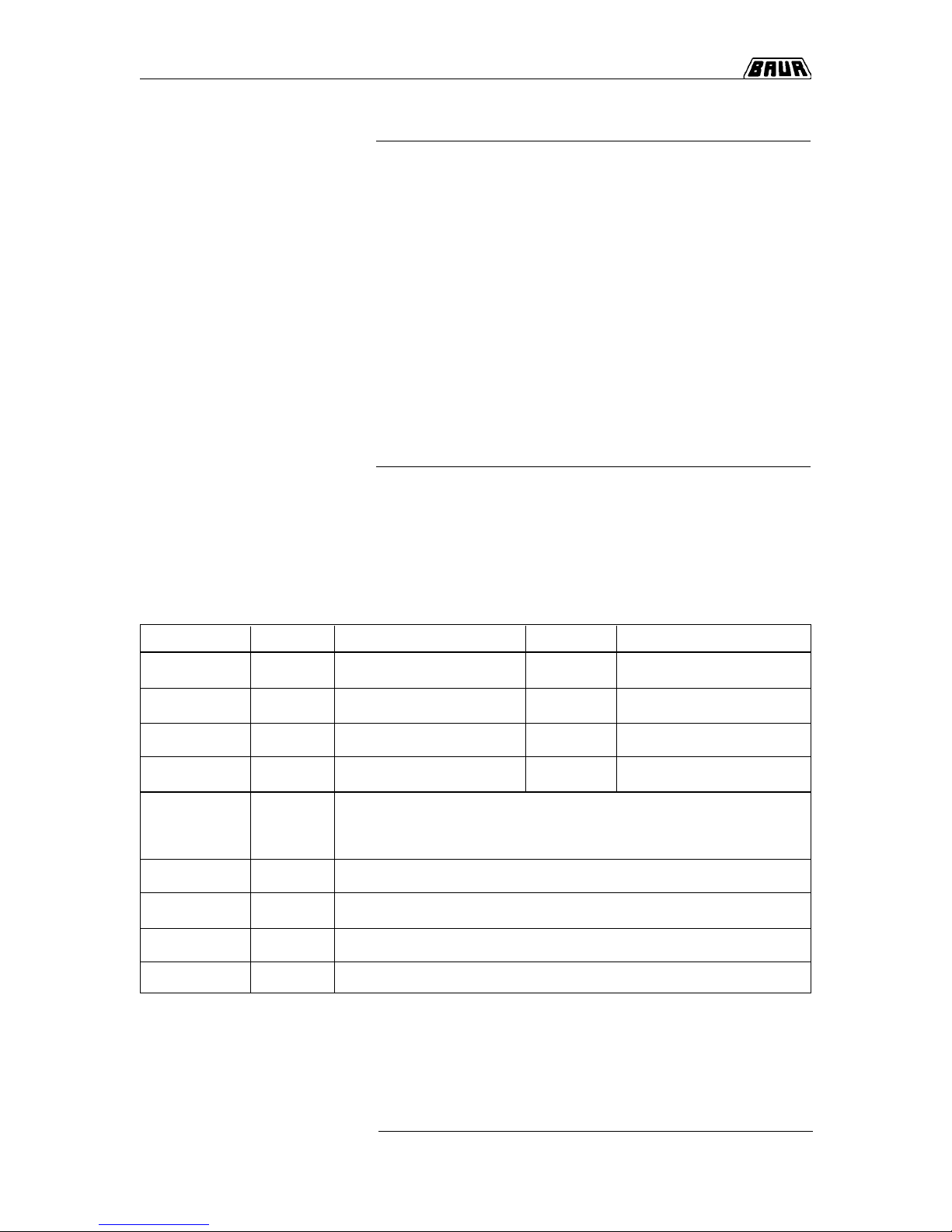
Designation Value Dimension Ident.No. Remarks
F1, F2 0,16 AT Ø 5 x 20 mm 563-005 Mains transformer, primary
F3, F4 2 AF Ø 5 x 20 mm 563-020 + 12V control
F5, F6 3,15 AT Ø 5 x 20 mm 563-021 Discharge unit (option)
(S4, F10) 16 AT Mains switch
F11
PGK 70 HB 2 A High voltage transformer, primary
PGK 1 10 HB 6 A High voltage transformer, primary
PGK 150 HB 6 A High voltage transformer, primary
PGK 260 HB 10 A High voltage transformer, primary
PGK 70/2,5 HB 14 A High voltage transformer, primary
Page 27

5-1
5. Options, Accessories and Ordering Information
In this section you will find all necessary information regarding
options and accessories available for the High Volt age Testing Sets
PGK 70 HB, PGK 70 - 2.5 HB, PGK 1 10 HB, PGK 150 HB and
PGK 260 HB.
5. Options, Accessories and Ordering Information
Overview
This section contains the following subjects:
Subject Page
Options 5-2
Accessories 5-3
Ordering information 5-5
Page 28

5. Options, Accessories and Ordering Information
5-2
For PGK HB instruments an automatic discharge unit is available
consisting of a short-circuit bar activated by a rotary magnet and a
discharge resistor connected in series between test object and test
instrument. Control is accomplished via the operating unit. By
pressing pushbutton ‘Ready to switch on’ (2) the short-circuit
bar is moved away from the corona protection hood. Reaching the
end position is monitored. When the instrument is back in operating
condition ‘READY FOR OPERATION’ a short-circuit bar is moved
to the corona protection hood by a spring. A discharge resistor is
responsible for discharging the connected capacitances.
As additional accessory a folding tripod can be supplied. It makes
operation of the instrument easier if no working table is available.
Working height is approx. 90cm.
In order to make shipping of the PGK HB Sets to the customers
easier a transport case is available.
For the H.V . unit s a moving frame with big steering rollers can be
supplied.
Options
Folding tripod
Discharge unit
Moving frame
Transport case
Page 29

5-3
5. Options, Accessories and Ordering Information
PGK unit 70 HB 70 - 2,5 HB 110 HB 150 HB 260 HB
Discharge bar ES 70 ES 70 ES 110 ES 150 ES 260
max. permissible
voltage 80 kV 80 kV 120 kV 180 kV 280 kV
max. permissible
discharge energy 12.000 Ws 12.000 Ws 18.000 Ws 27.000 Ws 42.000 Ws
Time between
2 discharges 10 min. 10 min. 10 min. 10 min. 10 min.
Accessories
The PGK HB instruments are supplied with the accessories
specified below. The rectifier bar is in the H.V. unit when supplied
and the instrument is in the operating mode ‘negative D.C.’.
The rectifier bar supplied with the instrument is used for protecting
the instrument against transient voltages and high currents in case
of short-circuit during A.C. operation.
Rectifier bar (option with PGK 260)
PGK unit 70 HB 70/2,5 HB 1 10 HB 150 HB 260 HB
Resistance value 33 kΩ 3 kΩ 30 kΩ 99 k Ω 132 kΩ
Tolerance ± 10 % ± 10 % ± 10 % ± 10 % ± 10 %
Is used for loosening the threaded insert when changing the
operating mode of the instrument. It is a cylindrical spanner which
is inserted into the two holes in the threaded insert.
Spanner for replacing rectifier /
resistor bar
For discharging capacitive test objects during D.C. operation the
discharge bars ES 70 - ES 260 are used.
Discharge bar
As earth connection between H.V. unit and test object a flexible
copper earth lead with a length of 2,5 m and a cross-section of
4mm² is supplied. On both ends cable lugs are attached with a hole
diameter of 8,5 mm.
Earth lead
Page 30

5. Options, Accessories and Ordering Information
5-4
Mains supply
Connection H.V. / Operating unit
High Voltage connecting leads
The PGK HB instruments are supplied with a plugable mains
supply cable with a 1,5 mm² cross-section and with a length of
2,5 m.
Ident.No. Type
554-015 Powercord with safety plug
554-016 Powercord with US plug
554-017 Powercord with free cable end
Connecting lead between H.V . and operating unit is 5 m long and is
connected with lockable connectors on both sides.
A High Voltage insulated wire with a length of 5 m and a crosssection of 1,5 mm² is used as High Voltage connecting lead.
The instrument side is equipped with a cable lug with hole diam.
8,5 mm (with PGK 70 HB a banana plug with 4 mm) and the test
object side is equipped with an alligator clip.
Page 31
5-5
5. Options, Accessories and Ordering Information
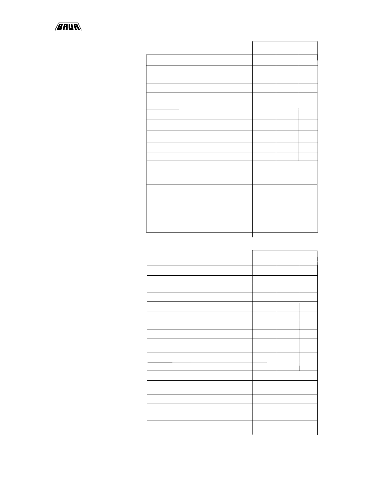
Mains voltage
220-230V 110-120V*) 240V
High Voltage Test Set PGK 70/2,5 HB 41 1-011 411-1 1 1 41 1-211
Operating unit 470-031 470-032 470-033
High Voltage unit 470-047 470-047 470-047
Discharge bar ES 70 12kWs 41 1-510 411-510 41 1-510
Mains connection 554-015 554-016**) 554-017
Connecting cable H.V . / Operating unit, 5 m 471-933 471-933 471-933
Earth lead, 3 m 460-462 460-462 460-462
High Voltage connection, 2,5 m with alligator clip 460-477 460-477 460-477
Spanner for replacing
rectifier / resistor bar 460-459 460-459 460-459
Rectifier bar (built in) 470-063 470-063 470-063
Resistor bar fo A.C. operation 470-064 470-064 470-064
Moving frame H.V . unit 470-577
Folding tripod for 19" units, working height
approx. 90 cm 41 1-536
Automatic discharge device EM 70/2,5, 45kWs 470-621
Emergency Off unit with signal lamps, 25 m 471-219
Emergency Off unit with signal lamps, 50 m 470-809
ransport case for H.V . / Operating unit 19" (WxHxD)
720x1716x720 mm 411-537
Mains voltage
220-230V 110-120V*) 240V
High Voltage Test Set PGK 70 HB with accessories 4 11-010 41 1-110 411-210
Operating unit 470-006 470-007 470-008
High Voltage unit 470-042 470-042 470-042
Discharge bar ES 70 12kWs 41 1-510 41 1-510 411-510
Mains connection 554-015 554-016 554-017
Connecting cable H.V . / Operating unit, 5 m 471-933 471-933 471-933
Earth lead, 3 m 460-462 460-462 460-462
High Voltage connection, 2,5 m with alligator clip 460-476 460-476 460-476
Spanner for replacing
rectifier / resistor bar 460-459 460-459 460-459
Rectifier bar (built in) 470-062 470-062 470-062
Resistor bar fo A.C. operation 470-061 470-061 470-061
Folding tripod for 19" units, working height
approx. 90cm 41 1-536
Automatic discharge device EM 70, 20kWs 470-620
Emergency Off unit with signal lamps, 25 m 471-219
Emergency Off unit with signal lamps, 50 m 470-809
Transport case for operating unit 19" (WxHxD)
626x383x382 mm 470-765
Transport case for High V oltage unit (WxHxD)
440x940x440 mm 411-530
Ordering information PGK 70 HB
Item supplied
Item supplied
Ordering information PGK 70/2,5 HB
Options
Optionen
*): Delivery includes external autotransformer; mains connection cable without termination, fix mounted **) fix installed mains connection
*): Delivery includes external autotransformer; mains connection cable without
termination, fix mounted
Page 32
5. Options, Accessories and Ordering Information
5-6
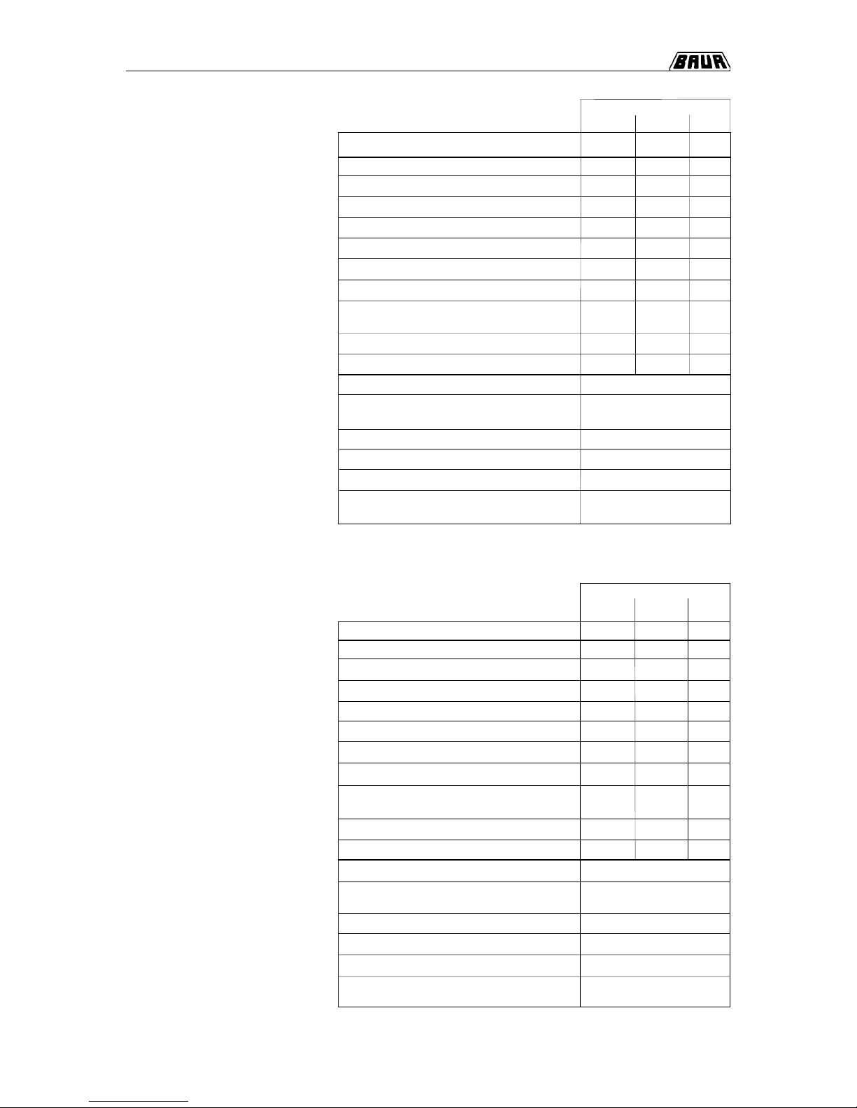
Mains voltage
220-230V 110-120V*) 240V
High Voltage Test Set PGK 1 10 HB with accessories 411-017 411-117 411-217
Operating unit 470-444 470-445 470-446
High Voltage unit 470-449 470-449 470-449
Discharge bar ES 110 18kWs 41 1-511 41 1-511 411-51 1
Mains connection 554-015 554-016 554-017
Connecting cable H.V . / Operating unit, 5 m 471-933 471-933 471-933
Earth lead, 3 m 460-462 460-462 460-462
High Voltage connection, 2,5 m with alligator clip 460-477 460-477 460-477
Spanner for replacing
rectifier / resistor bar 460-459 460-459 460-459
Rectifier bar (built in) 470-439 470-439 470-439
Resistor bar for A.C. operation 470-440 470-440 470-440
Moving frame High Volt age unit 470-577
Folding tripod for 19" units,
working height approx. 90 cm 41 1-536
Automatic discharge device EM 110, 45kWs 470-622
Emergency Off unit with signal lamps, 25 m 471-219
Emergency Off unit with signal lamps, 50 m 470-809
Transport case for H.V . / Operating unit (WxHxD)
670x1680x760 mm 471-179
Ordering information PGK 110 HB
Items supplied
Ordering information PGK 150 HB
220-230V 110-120V*) 240V
High Voltage Test Set PGK 150 HB with accessories 41 1-013 41 1-113 411-213
Operating unit 470-016 470-017 470-018
High Voltage unit 470-044 470-044 470-044
Discharge bar ES 150 41 1-512 411-512 41 1-512
Mains connection 554-015 554-016 554-017
Connection cable H.V . / Operating unit, 5 m 471-933 471-933 471-933
Earth lead, 3 m 460-462 460-462 460-462
High Voltage connection, 2,5 m with alligator clip 460-477 460-477 460-477
Spanner for replacing
rectifier / resistor bar 46 0-459 460-459 460-459
Rectifier bar (built-in) 4 70-057 470-057 470-057
Resistor bar for A.C. operation 4 70-058 470-058 470-058
Moving frame High Voltage unit 470-577
Folding tripod for 19" units,
working height approx. 90 cm 41 1-536
Automatic discharge device EM 150, 45kWs 470-624
Emergency Off unit with signal lamps, 25 m 471-219
Emergency Off unit with signal lamps, 50 m 470-809
Transport case for H.V . / Operating unit (WxHxD)
720x720x1970 mm 471-178
Mains voltage
Items supplied
Options
Options
*): Delivery includes external autotransformer; mains connection cable without
termination, fix mounted
*): Delivery includes external autotransformer; mains connection cable without
termination, fix mounted
Page 33
5-7
5. Options, Accessories and Ordering Information
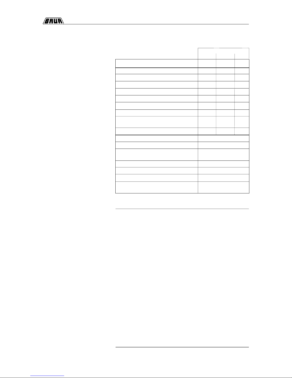
Mains voltage
220-230V 110-120V*) 240V
High Voltage Test Set PGK 260 HB with accessories 411-016 411-116 411-216
Operating unit 470-026 470-027 470-028
High Voltage unit 470-046 470-046 470-046
Discharge bar ES 260 42kWs 41 1-514 411-514 411-514
Mains connection 554-015 554-016 554-017
Connection cable H.V . / Operating unit, 5 m 471-933 471-933 471-933
Earth lead 3 m 460-462 460-462 460-462
High Voltage connection, 2,5 m with alligator clip 460-477 460-477 460-477
Spanner for replacing
rectifier / resistor bar 460-459 460-459 460-459
Rectifier bar (built in) 470-060 470-060 470-060
Resistor bar for A.C. operation 470-059
Moving frame High Voltage unit 470-584
Folding tripod for 19" units,
working height approx. 90 cm 41 1-536
Automatic discharge device EM 260 470-627
Emergency Off unit with signal lamps, 25 m 471-219
Emergency Off unit with signal lamps, 50 m 470-809
Transport case for H.V . / Operating unit (WxHxD)
1350x2220x1350 mm 411-533
Items supplied
Ordering information PGK 260 HB
Options
*): Delivery includes external autotransformer; mains connection cable without
termination, fix mounted
Page 34

5. Options, Accessories and Ordering Information
5-8
Notes
○○○○○○○○○○○○○○○○○○○○○○○○○○○○○○○○○○○○○○
○○○○○○○○○○○○○○○○○○○○○○○○○○○○○○○○○○○○○○
○○○○○○○○○○○○○○○○○○○○○○○○○○○○○○○○○○○○○○
○○○○○○○○○○○○○○○○○○○○○○○○○○○○○○○○○○○○○○
○○○○○○○○○○○○○○○○○○○○○○○○○○○○○○○○○○○○○○
○○○○○○○○○○○○○○○○○○○○○○○○○○○○○○○○○○○○○○
○○○○○○○○○○○○○○○○○○○○○○○○○○○○○○○○○○○○○○
○○○○○○○○○○○○○○○○○○○○○○○○○○○○○○○○○○○○○○
○○○○○○○○○○○○○○○○○○○○○○○○○○○○○○○○○○○○○○
○○○○○○○○○○○○○○○○○○○○○○○○○○○○○○○○○○○○○○
○○○○○○○○○○○○○○○○○○○○○○○○○○○○○○○○○○○○○○
○○○○○○○○○○○○○○○○○○○○○○○○○○○○○○○○○○○○○○
○○○○○○○○○○○○○○○○○○○○○○○○○○○○○○○○○○○○○○
○○○○○○○○○○○○○○○○○○○○○○○○○○○○○○○○○○○○○○
○○○○○○○○○○○○○○○○○○○○○○○○○○○○○○○○○○○○○○
○○○○○○○○○○○○○○○○○○○○○○○○○○○○○○○○○○○○○○
○○○○○○○○○○○○○○○○○○○○○○○○○○○○○○○○○○○○○○
○○○○○○○○○○○○○○○○○○○○○○○○○○○○○○○○○○○○○○
○○○○○○○○○○○○○○○○○○○○○○○○○○○○○○○○○○○○○○
○○○○○○○○○○○○○○○○○○○○○○○○○○○○○○○○○○○○○○
○○○○○○○○○○○○○○○○○○○○○○○○○○○○○○○○○○○○○○
○○○○○○○○○○○○○○○○○○○○○○○○○○○○○○○○○○○○○○
○○○○○○○○○○○○○○○○○○○○○○○○○○○○○○○○○○○○○○
 Loading...