


Operating Instructions
Language English
Translation
Document-No. 5.08009.05
Part No. 422585
Status 11.03.2015
E
5.08009.05
b maXX
Safety I/O Terminals
SI4000 / SO4000
Read the Operating Instructions before beginning
®
Systems

Baumüller Nürnberg GmbH
Ostendstr. 80 - 90
90482 Nürnberg
Germany
Tel. +49 9 11 5432 - 0
Fax: +49 9 11 54 32 - 1 30
E-Mail: mail@baumueller.de
Internet: www.baumueller.de

Table of Contents
1 Preface . . . . . . . . . . . . . . . . . . . . . . . . . . . . . . . . . . . . . . . . . . . . . . . . . . . . . . . . . . . . . . . . . . 7
1.1 Information on the Operation Manual . . . . . . . . . . . . . . . . . . . . . . . . . . . . . . . . . . . . . . 7
1.2 Legend. . . . . . . . . . . . . . . . . . . . . . . . . . . . . . . . . . . . . . . . . . . . . . . . . . . . . . . . . . . . . . 8
1.3 Limitation of liability . . . . . . . . . . . . . . . . . . . . . . . . . . . . . . . . . . . . . . . . . . . . . . . . . . . . 9
1.4 Preliminary information . . . . . . . . . . . . . . . . . . . . . . . . . . . . . . . . . . . . . . . . . . . . . . . . . 9
1.5 Copyright . . . . . . . . . . . . . . . . . . . . . . . . . . . . . . . . . . . . . . . . . . . . . . . . . . . . . . . . . . . 10
1.6 Further applicable documents . . . . . . . . . . . . . . . . . . . . . . . . . . . . . . . . . . . . . . . . . . . 10
1.7 Replacement parts. . . . . . . . . . . . . . . . . . . . . . . . . . . . . . . . . . . . . . . . . . . . . . . . . . . . 10
1.8 Disposal . . . . . . . . . . . . . . . . . . . . . . . . . . . . . . . . . . . . . . . . . . . . . . . . . . . . . . . . . . . . 10
1.9 Warranty conditions . . . . . . . . . . . . . . . . . . . . . . . . . . . . . . . . . . . . . . . . . . . . . . . . . . . 11
1.10 Customer service. . . . . . . . . . . . . . . . . . . . . . . . . . . . . . . . . . . . . . . . . . . . . . . . . . . . . 11
1.11 Terms used . . . . . . . . . . . . . . . . . . . . . . . . . . . . . . . . . . . . . . . . . . . . . . . . . . . . . . . . . 11
1.12 Certification . . . . . . . . . . . . . . . . . . . . . . . . . . . . . . . . . . . . . . . . . . . . . . . . . . . . . . . . . 11
1.12.1 Approvals, directives and standards . . . . . . . . . . . . . . . . . . . . . . . . . . . . . . . . . . . . . 12
2 Use of this handbook . . . . . . . . . . . . . . . . . . . . . . . . . . . . . . . . . . . . . . . . . . . . . . . . . . . . . 13
3 Safety . . . . . . . . . . . . . . . . . . . . . . . . . . . . . . . . . . . . . . . . . . . . . . . . . . . . . . . . . . . . . . . . . . 15
3.1 Contents of the Operation Manual. . . . . . . . . . . . . . . . . . . . . . . . . . . . . . . . . . . . . . . . 15
3.2 Alterations and rebuilding of the device. . . . . . . . . . . . . . . . . . . . . . . . . . . . . . . . . . . . 15
3.3 Appropriate use . . . . . . . . . . . . . . . . . . . . . . . . . . . . . . . . . . . . . . . . . . . . . . . . . . . . . . 15
3.4 Operator responsibility. . . . . . . . . . . . . . . . . . . . . . . . . . . . . . . . . . . . . . . . . . . . . . . . . 17
3.5 Protective equipment . . . . . . . . . . . . . . . . . . . . . . . . . . . . . . . . . . . . . . . . . . . . . . . . . . 17
3.6 Personnel training . . . . . . . . . . . . . . . . . . . . . . . . . . . . . . . . . . . . . . . . . . . . . . . . . . . . 18
3.7 Personnel protective equipment . . . . . . . . . . . . . . . . . . . . . . . . . . . . . . . . . . . . . . . . . 19
3.8 Special dangers . . . . . . . . . . . . . . . . . . . . . . . . . . . . . . . . . . . . . . . . . . . . . . . . . . . . . . 20
3.9 Firefighting . . . . . . . . . . . . . . . . . . . . . . . . . . . . . . . . . . . . . . . . . . . . . . . . . . . . . . . . . . 21
3.10 Electric safety . . . . . . . . . . . . . . . . . . . . . . . . . . . . . . . . . . . . . . . . . . . . . . . . . . . . . . . 22
3.10.1 Notice on power supply. . . . . . . . . . . . . . . . . . . . . . . . . . . . . . . . . . . . . . . . . . . . . . . 22
3.11 Safety equipment. . . . . . . . . . . . . . . . . . . . . . . . . . . . . . . . . . . . . . . . . . . . . . . . . . . . . 22
3.12 Conduct in the event of danger and accidents . . . . . . . . . . . . . . . . . . . . . . . . . . . . . . 23
3.13 Signage . . . . . . . . . . . . . . . . . . . . . . . . . . . . . . . . . . . . . . . . . . . . . . . . . . . . . . . . . . . . 24
4 Functional Safety. . . . . . . . . . . . . . . . . . . . . . . . . . . . . . . . . . . . . . . . . . . . . . . . . . . . . . . . . 25
4.1 Safety-related parameters . . . . . . . . . . . . . . . . . . . . . . . . . . . . . . . . . . . . . . . . . . . . . . 25
4.2 Lifetime . . . . . . . . . . . . . . . . . . . . . . . . . . . . . . . . . . . . . . . . . . . . . . . . . . . . . . . . . . . . 26
4.3 Using of the terminals with b maXX safe PLC . . . . . . . . . . . . . . . . . . . . . . . . . . . . . . . 27
5 Description of the Safety I/O Terminals. . . . . . . . . . . . . . . . . . . . . . . . . . . . . . . . . . . . . . . 29
5.1 General description . . . . . . . . . . . . . . . . . . . . . . . . . . . . . . . . . . . . . . . . . . . . . . . . . . . 29
5.1.1 SI4000 4-channel safety digital input terminal. . . . . . . . . . . . . . . . . . . . . . . . . . . . . . 29
5.1.2 SO4000 4-channel safety digital output terminal. . . . . . . . . . . . . . . . . . . . . . . . . . . . 30
5.2 Appropriate use . . . . . . . . . . . . . . . . . . . . . . . . . . . . . . . . . . . . . . . . . . . . . . . . . . . . . . 31
5.3 Technical data . . . . . . . . . . . . . . . . . . . . . . . . . . . . . . . . . . . . . . . . . . . . . . . . . . . . . . . 31
5.4 Dimensions . . . . . . . . . . . . . . . . . . . . . . . . . . . . . . . . . . . . . . . . . . . . . . . . . . . . . . . . . 32
5.4.1 SI4000. . . . . . . . . . . . . . . . . . . . . . . . . . . . . . . . . . . . . . . . . . . . . . . . . . . . . . . . . . . . 32
5.4.2 SO4000 . . . . . . . . . . . . . . . . . . . . . . . . . . . . . . . . . . . . . . . . . . . . . . . . . . . . . . . . . . . 33
6 Assembly and Installation. . . . . . . . . . . . . . . . . . . . . . . . . . . . . . . . . . . . . . . . . . . . . . . . . . 35
6.1 Safety instructions . . . . . . . . . . . . . . . . . . . . . . . . . . . . . . . . . . . . . . . . . . . . . . . . . . . . 35
Operating Instructions Safety I/O Terminals SI4000 / SO4000
Dokument-Nr.: 5.08009.05
3
of 82

Inhaltsverzeichnis
6.2 Transport and storage . . . . . . . . . . . . . . . . . . . . . . . . . . . . . . . . . . . . . . . . . . . . . . . . . 35
6.3 Installation of Bus Terminals on C mounting rails . . . . . . . . . . . . . . . . . . . . . . . . . . . . 36
6.3.1 Control cabinet. . . . . . . . . . . . . . . . . . . . . . . . . . . . . . . . . . . . . . . . . . . . . . . . . . . . . . 36
6.3.2 Mounting rail installation . . . . . . . . . . . . . . . . . . . . . . . . . . . . . . . . . . . . . . . . . . . . . . 36
6.4 Electrical installation. . . . . . . . . . . . . . . . . . . . . . . . . . . . . . . . . . . . . . . . . . . . . . . . . . . 37
6.4.1 Connections within a bus terminal block . . . . . . . . . . . . . . . . . . . . . . . . . . . . . . . . . . 37
6.4.2 Wiring. . . . . . . . . . . . . . . . . . . . . . . . . . . . . . . . . . . . . . . . . . . . . . . . . . . . . . . . . . . . . 39
6.5 Power supply . . . . . . . . . . . . . . . . . . . . . . . . . . . . . . . . . . . . . . . . . . . . . . . . . . . . . . . . 39
7 Commissioning. . . . . . . . . . . . . . . . . . . . . . . . . . . . . . . . . . . . . . . . . . . . . . . . . . . . . . . . . . . 41
7.1 Installation . . . . . . . . . . . . . . . . . . . . . . . . . . . . . . . . . . . . . . . . . . . . . . . . . . . . . . . . . . 42
7.1.1 Safety instructions . . . . . . . . . . . . . . . . . . . . . . . . . . . . . . . . . . . . . . . . . . . . . . . . . . . 42
7.1.2 Transport and storage . . . . . . . . . . . . . . . . . . . . . . . . . . . . . . . . . . . . . . . . . . . . . . . . 42
7.1.3 Mechanical installation. . . . . . . . . . . . . . . . . . . . . . . . . . . . . . . . . . . . . . . . . . . . . . . . 42
7.1.4 Electrical installation . . . . . . . . . . . . . . . . . . . . . . . . . . . . . . . . . . . . . . . . . . . . . . . . . 42
7.1.5 SI4000 pin assignment . . . . . . . . . . . . . . . . . . . . . . . . . . . . . . . . . . . . . . . . . . . . . . . 43
7.1.6 SO4000 pin assignment . . . . . . . . . . . . . . . . . . . . . . . . . . . . . . . . . . . . . . . . . . . . . . 45
7.1.7 Address settings on the safety terminals . . . . . . . . . . . . . . . . . . . . . . . . . . . . . . . . . . 47
7.1.8 Parameterization . . . . . . . . . . . . . . . . . . . . . . . . . . . . . . . . . . . . . . . . . . . . . . . . . . . . 48
7.2 Diagnostic. . . . . . . . . . . . . . . . . . . . . . . . . . . . . . . . . . . . . . . . . . . . . . . . . . . . . . . . . . . 54
7.2.1 Diagnostic LEDs SI4000 . . . . . . . . . . . . . . . . . . . . . . . . . . . . . . . . . . . . . . . . . . . . . . 54
7.2.2 Diagnostic LEDs SO4000 . . . . . . . . . . . . . . . . . . . . . . . . . . . . . . . . . . . . . . . . . . . . . 56
7.3 Troubleshooting . . . . . . . . . . . . . . . . . . . . . . . . . . . . . . . . . . . . . . . . . . . . . . . . . . . . . . 57
7.4 Maintenance. . . . . . . . . . . . . . . . . . . . . . . . . . . . . . . . . . . . . . . . . . . . . . . . . . . . . . . . . 58
7.4.1 Cleaning. . . . . . . . . . . . . . . . . . . . . . . . . . . . . . . . . . . . . . . . . . . . . . . . . . . . . . . . . . . 58
7.4.2 Service life . . . . . . . . . . . . . . . . . . . . . . . . . . . . . . . . . . . . . . . . . . . . . . . . . . . . . . . . . 58
8 System validation. . . . . . . . . . . . . . . . . . . . . . . . . . . . . . . . . . . . . . . . . . . . . . . . . . . . . . . . . 59
8.1 Function test. . . . . . . . . . . . . . . . . . . . . . . . . . . . . . . . . . . . . . . . . . . . . . . . . . . . . . . . . 59
9 Dismantling, storage . . . . . . . . . . . . . . . . . . . . . . . . . . . . . . . . . . . . . . . . . . . . . . . . . . . . . . 61
9.1 Safety regulations. . . . . . . . . . . . . . . . . . . . . . . . . . . . . . . . . . . . . . . . . . . . . . . . . . . . . 61
9.2 Requirements of the personnel carrying out work . . . . . . . . . . . . . . . . . . . . . . . . . . . . 61
9.3 Decommissioning . . . . . . . . . . . . . . . . . . . . . . . . . . . . . . . . . . . . . . . . . . . . . . . . . . . . . 61
9.4 Disassembly . . . . . . . . . . . . . . . . . . . . . . . . . . . . . . . . . . . . . . . . . . . . . . . . . . . . . . . . . 61
9.5 Storage conditions . . . . . . . . . . . . . . . . . . . . . . . . . . . . . . . . . . . . . . . . . . . . . . . . . . . . 62
9.6 Recommissioning . . . . . . . . . . . . . . . . . . . . . . . . . . . . . . . . . . . . . . . . . . . . . . . . . . . . . 62
9.7 Disposal . . . . . . . . . . . . . . . . . . . . . . . . . . . . . . . . . . . . . . . . . . . . . . . . . . . . . . . . . . . . 62
Appendix A - Abbreviations . . . . . . . . . . . . . . . . . . . . . . . . . . . . . . . . . . . . . . . . . . . . . . . . . . . 63
Appendix B - Accessories . . . . . . . . . . . . . . . . . . . . . . . . . . . . . . . . . . . . . . . . . . . . . . . . . . . . 65
B.1 List of all accessory items . . . . . . . . . . . . . . . . . . . . . . . . . . . . . . . . . . . . . . . . . . . . . . . 65
Appendix C - Checklists . . . . . . . . . . . . . . . . . . . . . . . . . . . . . . . . . . . . . . . . . . . . . . . . . . . . . . 67
C.1 Installation checklist . . . . . . . . . . . . . . . . . . . . . . . . . . . . . . . . . . . . . . . . . . . . . . . . . . . 67
C.2 Commissioning and validation checklist . . . . . . . . . . . . . . . . . . . . . . . . . . . . . . . . . . . . 69
Appendix D - Technical Data . . . . . . . . . . . . . . . . . . . . . . . . . . . . . . . . . . . . . . . . . . . . . . . . . . 71
D.1 Connection technology . . . . . . . . . . . . . . . . . . . . . . . . . . . . . . . . . . . . . . . . . . . . . . . . . 71
D.2 Connection values. . . . . . . . . . . . . . . . . . . . . . . . . . . . . . . . . . . . . . . . . . . . . . . . . . . . . 71
D.3 Operating conditions . . . . . . . . . . . . . . . . . . . . . . . . . . . . . . . . . . . . . . . . . . . . . . . . . . . 74
4
of 82
Appendix E - Declaration of Conformity . . . . . . . . . . . . . . . . . . . . . . . . . . . . . . . . . . . . . . . . . 77
E.1 What is an EC directive? . . . . . . . . . . . . . . . . . . . . . . . . . . . . . . . . . . . . . . . . . . . . . . . . 77
E.2 What the CE symbol indicates . . . . . . . . . . . . . . . . . . . . . . . . . . . . . . . . . . . . . . . . . . . 77
Operating Instructions Safety I/O Terminals SI4000 / SO4000
Dokument-Nr.: 5.08009.05 Baumüller Nürnberg GmbH

Inhaltsverzeichnis
E.3 Definition of the term Declaration of Conformity. . . . . . . . . . . . . . . . . . . . . . . . . . . . . . 78
E.4 Declaration of Conformity . . . . . . . . . . . . . . . . . . . . . . . . . . . . . . . . . . . . . . . . . . . . . . . 78
Index . . . . . . . . . . . . . . . . . . . . . . . . . . . . . . . . . . . . . . . . . . . . . . . . . . . . . . . . . . . . . . . . . . . . . . 81
Operating Instructions Safety I/O Terminals SI4000 / SO4000
Dokument-Nr.: 5.08009.05
5
of 82

6
of 82
Operating Instructions Safety I/O Terminals SI4000 / SO4000
Dokument-Nr.: 5.08009.05 Baumüller Nürnberg GmbH

1.1 Information on the Operation Manual
This Operation Manual provides important information on handling the device. Compliance with all safety instructions operation instructions specified is a prerequisite for work
safety.
Furthermore, it is also necessary to comply with the local accident prevention legislation
and general safety regulations applying to the device’s field of application.
Read the Operation Manual completely, in particular the chapter on safety instructions,
before beginning any work on the device. The Operation Manual is a component of the
product and must be kept accessible to personnel in the immediate vicinity of the device
at all times.
1PREFACE
Operation Manual Safety I/O Terminals SI4000 / SO4000
Document no.: 5.08009.05
7
of 82

1.2
Legend
1.2 Legend
Warning notices
Warning notices are indicated by symbols in this Op
troduced by signal words which express the extent of the hazard.
Comply with the notices under all circumstances an
accidents, personal injury and property damage.
DANGER!
eration Manual. The notices are in-
d act with caution in order to avoid
....notifies of an imminent dangerous
juries if not avoided.
WARNING!
....notifies of a potentially dangerous situation which can lead to death or serious in-
juries if not avoided.
CAUTION!
....notifies of a potentially dangerous situation which can lead to minor or slight inju-
ries if not avoided.
NOTE!
....notifies of a potentially dangerous situation which can lead to property damage if
not avoided.
situation which will lead to death or serious in-
Recommendations
8
of 82
NOTICE!
....draws attention to useful tips and recommendations as well as information for effi-
cient and trouble-free operation.
Operation Manual Safety I/O Terminals SI4000 / SO4000
Document no.: 5.08009.05 Baumüller Nürnberg GmbH

1.3 Limitation of liability
All statements and instructions in this Operation Manual have been compiled in compliance with the applicable standards and legislation w
nology and our long-term experience an
The manufacturer assumes
m failure to observe the Operation Manual
m application for purposes other than those intended
m use by untrained personnel
hile taking the current level of tech-
d findings into account.
no liability for damages resulting from:
Preface
1
The actual scope of materials delivered may v
described here in cases involving custom designs or the use of additional ordering options, or as a result of the most recent changes in technology.
The user assumes the responsibility
accordance with the safety regulations of the applicable standards and all other relevant
national or regional legislation relating to conductor dimensioning and protection, grounding, circuit breakers, ove
The person who conducted the assembly or installation shall be accountable for damages
ring during assembly or connection.
occur
1.4 Preliminary information
CAUTION!
The following shall apply if the document you are reading is designated as preliminary
information:
This version pertains to preliminary technic
scribed devices and functions should receive ahead of time, in order to be able to adjust to potential changes and/or
This information is to be considered preliminary since it has not yet been subjected
the Baumüller internal review process. In particular, this information is still subject
to
to changes, meaning that this preliminary information cannot be construed as legally
binding. Baumüller assumes no liability for damages resulting from this potentially incorrect or incomplete version.
Should you detect or suspect content-related and/or serious formal errors in this preliminary information, please contact the contact person assigned to you and inform
us of your
tially incorporated during the transition from
(reviewed by Baumüller) information. The obligations specified in the following section under “Obligations” do not apply to preliminary information.
findings and comments, so that they can be taken into account and poten-
ary from the explanations and illustrations
of conducting maintenance and commissioning in
rvoltage protection, etc.
al information which the user of the de-
functional expansions.
the preliminary information to the final
Operation Manual Safety I/O Terminals SI4000 / SO4000
Document no.: 5.08009.05
9
of 82

1.5
Copyright
1.5 Copyright
Treat the Operation Manual as confidential. It is intended exclusively for those working
with the device. It is not permissible to transfer the Operation Manual to third parties without the written approval of the manufacturer.
NOTICE!
The content-related statements, texts, diagrams, images and
copyright protected and subject to industrial property rights. Any improper use is liable to prosecution.
b maXX
®
is a registered trademark of Baumüller Nürnberg GmbH
1.6 Further applicable documents
Components from other manufacturers are built into the device. Hazard evaluations for
these bought-in parts have been conducted by the applicable manufacturers. The conformity of the designs with the applicable Eur
clared by the respective comp
1.7 Replacement parts
WARNING!
Improper or defective replacement parts can
failure as well as jeopardize safety.
Therefore:
m Only use original replacement parts from the manufacturer
other illustrations are
opean and national legislation has been de-
onent manufacturers.
lead to damage, malfunctions or total
1.8 Disposal
10
of 82
Operation Manual Safety I/O Terminals SI4000 / SO4000
Document no.: 5.08009.05 Baumüller Nürnberg GmbH
Procure replacement parts from authorized dealers or directly from the manufacturer.
See also ZAppendix
If no return or disposal agreement has been made, dismantled components can be taken
for recycling after proper disassembly.
See also ZDisposal – o
B - Accessories– from page 65 onward.
n page 62.

1.9 Warranty conditions
The warranty conditions can be found as a separate document in the sales documentation.
The operation of the devices described here in accordance with the specified methods/
procedures/requirements is permissible. Everything else, even the operation of devices
in installation positions not depicted here, for instance, is not permissible and must be
clarified with the factor on a case-by-case basis. The warranty will be rendered null and
void if the devices are operated differently than described here.
1.10 Customer service
Our customer service is available for technical support.
Information on the contact person responsible can be found at any time via telephone,
fax, E-mail or over the internet (www.baumueller.de).
1.11 Terms used
Preface
1
1.12 Certification
The terms “SI4000” (for input terminal) or “SO4000” (for output terminal) are also used for
the product “Safety I/O Terminals.”
A list of the abbreviations used can be found in ZAppendix A - Abbreviations– from page
63 onward.
The safety I/O Terminals are a component part of a system composed of b maXX safe
PLC, power supply and other system modules.
The safety I/O Terminals have been developed in accordance with the standards specified in ZChapter 1.12.1– and certified by TÜV Süd.
SI4000:
Approval no. Z10 15 03 75013 001
Test report: BV82168T
SO4000:
Approval no. Z10 15 03 75013 003
Test report: BV82168T
Operation Manual Safety I/O Terminals SI4000 / SO4000
Document no.: 5.08009.05
11
of 82

1.12
1.12.1 Approvals, directives and standards
Certification
Safety engineering standards and directives
EN 61508, Parts 1-3 Functional safety of security-
DIN EN ISO 13849-1 Safety-related components of
Additional standards Area of application
2006/42/EC machinery directive
DIN EN 81-1 to the extent to which
EN 13243 to the extent to which
DIN EN 61000-6-2
DIN EN 61000-6-4
Area of application Approvals
up to SIL 3
related electric, electronic and
programmable electronic systems
up to performance
control units
e (category 4)
level
they may be applica-
ble
they may be applica-
ble
12
of 82
Operation Manual Safety I/O Terminals SI4000 / SO4000
Document no.: 5.08009.05 Baumüller Nürnberg GmbH

2USE OF THIS HANDBOOK
This safety handbook contains information on the intended use of the Baumüller safety
I/O terminals.
Knowledge of regulations and proper technical implementation of the safety instructions
in this handbook by qualified personnel are prerequisites for the safe installation, commis
sioning and safety during the operation and maintenance of the Baumüller safety I/O terminals. Unqualified interventions in the devices, during shutdown or use of the safety
functions or failure to comply with the instructions of this handbook can lead to serious
personal injury, property damage or environmental harm, for which Baumüller assumes
no liability.
Baumüller control devices are developed, manufactured and tested in compliance with
the applicable safety standards. They may only be used under the specified environmen
tal conductions and only in connection with approved external devices.
The Operation Manual contains safety instructions, descriptions of the interfaces and information on the phases of the product’s life cycle:
n Installation/Assembly
n Commissioning
n Operation
n Troubleshooting
n Maintenance/repair
n Disassembly
-
-
Operation Manual Safety I/O Terminals SI4000 / SO4000
Document no.: 5.08009.05
13
of 82

14
of 82
Operation Manual Safety I/O Terminals SI4000 / SO4000
Document no.: 5.08009.05 Baumüller Nürnberg GmbH

This section provides an overview of all important safety aspects for the optimum protection of the personnel as well as for safe and trouble-free operation.
3.1 Contents of the Operation Manual
All persons assigned to work on or with the device must have read and understood that
Operation Manual before beginning work with the device. This also applies if the person
concerned has already worked with such a device or similar device or has been trained
by the manufacturer.
3.2 Alterations and rebuilding of the device
In order to avoid hazards and ensure optimum performance, neither alterations, additions
nor rebuilding work may be conducted on the device unless explicitly authorized by the
manufacturer.
3SAFETY
3.3 Appropriate use
WARNING!
Caution - Risk of injury
Safety terminals may only be used for the purposes described below!
The safety terminals expand the application range of Baumüller bus terminals with functions that enable them to be used for machine safety applications. The safety terminals
e designed for machine safety functions and directly associated industrial automation
ar
tasks. They are therefore only approved for applications with a defined fail-safe state.This
safe state is the wattless state. Fail-safety according to the relevant standards is required.
Operation Manual Safety I/O Terminals SI4000 / SO4000
Document no.: 5.08009.05
15
of 82

3.3
Appropriate use
The safety terminals enable connection of:
m 24 V
emergency stop push buttons, pu
switches, safety mats, light curtains, light barriers, laser scanners etc.
m 24 V
contactors, protection door switches with tumble
NOTICE!
Test pulses
When selecting actuators please ensure that the SO4000 test pulses do not lead to
tuator switching or diagnostic message from the SO4000. The test pulses of the
ac
SO4000 terminal outputs are not configurable and cannot be switched off.
sensors (SI4000) such as
DC
actuators (SO4000) such as
DC
ll cord switches, position switches, two-hand
r, signal lamps, servo drives etc.
The following modules were developed f
m The SI4000 terminal is an input module with digital inputs.
m The SO4000 terminal is an output module with digital outputs.
These modules are suitable for operation with
m Baumüller b maXX safe PLC
m Baumüller ECK000 series bus coupler
Your use of the device is considered to be comp
all instructions and information in this Operation Manual.
WARNING!
Follow the machinery directive
The safety terminals may only be used in machines according to the Machinery Directive.
WARNING!
Ensure traceability
The buyer has to ensure the traceability
or these tasks:
liant with its intended use if you have read
of the device via the serial number.
16
of 82
Operation Manual Safety I/O Terminals SI4000 / SO4000
Document no.: 5.08009.05 Baumüller Nürnberg GmbH

WARNING!
Danger due to use other than intended!
Safety
3
Any use of the device different from and/o
ed use can lead to dangerous situations.
Therefore:
m Only use the device as intended.
m Follow all specifications of this
m Ensure that exclusively qualified per
m Take care in project planning to see that the device i
ifications.
m The device and/or mounting rail is mounted on a w
m Ensure that the power supply meets the
m Only operate the device if it is in technically faultless condition.
m Only use the device in combination with co
berg GmbH.
3.4 Operator responsibility
The device is implemented in an industrial zone. The operator of the device is thus subject to the legal work safety obligations
In addition to the work safety in
prevention and environmental protection regulations applicable to the area of application
of this device must also be complied with. In doing so, the following applies in particular:
m The operator must inform himself of the applicab
tionally ascertain hazards arise through the special w
of the device in a risk assessment. The operator must implement this in the form of operation instructions for the operation of the device.
m This Operation Manual must be kept in the
cessible to persons working on and with the device at all times.
m The statements of the Operation Manual are to b
m The device may only be operated in technically fau
operation.
r exceeding beyond the scope of the intend-
Operation Manual.
sonnel work on or with this device.
s always used within its spec-
all which is sufficiently sturdy.
required specifications.
mponents approved by Baumüller Nürn-
.
structions in this Operation Manual, the safety, accident
le work safety regulations and addi-
ork conditions at the place of use
immediate vicinity of the device and be ac-
e followed completely and absolutely!
ltless condition and must be safe for
3.5 Protective equipment
Protection category
All SI4000 and SO4000 devices with the couple stations (b maXX safe PLC or bus coupler) must be built into a suitable electrical cabinet in order to comply with the protective
catego
ries (IP54) required in EN 60529.
SI4000 IP 20
SO4000 IP 20
Operation Manual Safety I/O Terminals SI4000 / SO4000
Document no.: 5.08009.05
17
of 82

3.6
Personnel training
DANGER!
Life-threatening danger through electric current!
Immediate life-threatening danger is present if
Therefore:
m Operate the device in an electrical cabinet which p
contact with the devices and meets at least the protective categories (IP54) of
EN 60529.
3.6 Personnel training
WARNING!
Risk of injury if operated by insufficiently qualified persons!
Improper handling can lead to severe personal injury and property damage.
contact with live parts is made.
rovides protection from direct
Therefore:
m Only allow certain activities to be conducted b
chapters of this Operation Manual.
The following qualifications for various areas o
Manual:
m Operating personnel
The drive system may only be operated by p
and authorized to do so.
Troubleshooting, repairs, cleaning, maintena
ed by trained or instructed pers
tion Manual and act according to it.
Commissioning and instruction may only b
m Qualified personnel
Electrical engineers and specialist electricians of
authorized by Baumüller Anlagen-Systemtechnik GmbH & Co. KG, trained and certified in the installation and commissioning of Baumüller drive systems and commissioning, grounding and designating electrical systems and devices in ac
safety engineering standards.
Qualified personnel is educated or trained in
ty equipment in accordance with the respective
onnel. These persons must be familiar with the Opera-
y persons specified in the respective
f operation are specified in the Operation
ersons who have been trained, instructed
nce and exchange may only be conduct-
e conducted by qualified personnel.
the customer or a third party who are
cordance with the
the maintenance and use of suitable safe-
local safety engineering standards.
18
of 82
Operation Manual Safety I/O Terminals SI4000 / SO4000
Document no.: 5.08009.05 Baumüller Nürnberg GmbH

3.7 Personnel protective equipment
Wearing the appropriate personal protective equipment when working is required in order
to minimize hazards to the health.
m Always wear the respective protective equipment r
working.
m Observe signs on personal safety in the work area!
Protective work clothes
denotes tight-fitting work clothing with low tea
truding parts. It primarily serves in protecting from...
Do not wear any rings and necklaces.
Protective helmet
for protection from falling and flying
parts.
Safety
equired for the respective task when
r resistance, tight sleeves and no pro-
3
To be worn during
ecial work
sp
Safety shoes
for protection from heavy
Safety gloves
to protect the hands from friction, abrasions, pr
as from contact with hot objects.
Protective glasses
to protect the eyes from flying parts and spraying liquids
falling parts.
ick wounds or deeper injuries as well
Operation Manual Safety I/O Terminals SI4000 / SO4000
Document no.: 5.08009.05
19
of 82

3.8
Special dangers
3.8 Special dangers
The residual risks arising as a result of the hazard analysis will be specified in the following section.
Observe the safety instructions described here
chapters in order to reduce health hazards and avoid dangerous situations.
Electric current
DANGER!
Live-threatening danger from electric current!
Immediate life-threatening danger is present
age to the insulation or individual comp
Therefore:
m Shut down immediately if the insulation on the power supply is damaged.
m Only allow the work to be co
nel.
m Turn the current off when conducting any work on the electrical system and secure
it befo
and the warning notices in the following
if contact with live parts is made. Dam-
onent can be life-threatening.
nducted on the electrical system by qualified person-
re turning it back on.
Dangers from residual energy
DANGER!
Live-threatening danger from electric current!
After the device has been disconnected from
nectors may only be touched once the cap
charged.
Therefore:
m Take the capacitors’ discharge time into account and do not touch live parts be-
forehand.
m Follow commensurate instructions on the device.
m If you have connected additional capacitors to the
take considerably longer for the intermediate circuit to discharge. In such case, you
will have to establish the necessary waiting period yourself or measure whether
the device has been de-energized.
the mains, live parts such as line con-
acitors in the device have been dis-
intermediate circuit, it can also
20
of 82
Operation Manual Safety I/O Terminals SI4000 / SO4000
Document no.: 5.08009.05 Baumüller Nürnberg GmbH

Moving parts
3.9 Firefighting
Safety
WARNING!
Risk of energy from moving parts!
Rotating and/or linear moving parts can cause severe injuries.
Therefore:
m Do not interfere with moving parts during operation.
m Do not open covers during operation.
m The mechanical residual energy depends on the applic
also keep rotating/moving for a certain time after the power supply has been shut
off. Make sure to provide suitable safety equipment.
ation. Powered parts will
3
DANGER!
Live-threatening danger from electric current!
Electric shock can occur if a conductive
Therefore:
m Use the following fire extinguishing medium:
ABC powder/CO2
fire extinguishing medium is used.
Operation Manual Safety I/O Terminals SI4000 / SO4000
Document no.: 5.08009.05
21
of 82

3.10
Electric safety
3.10 Electric safety
The safety control is designed for contamination level 2 in accordance with EN 50178.
This means that only non-conductive contamination may appear during operating time.
Short-term conductivity from condensation is only permissible if the control is not in operation.
WARNING!
Risk of injury from conductive contaminants!
No conductive contaminants may appear during operating time.
Therefore:
m Before installing the system, check that contamination degree 2 is not exceeded,
nd ensure so by additional measures, if necessary.
a
3.10.1 Notice on power supply
WARNING!
Risk of injury from electric current!
Only devices which have a safe disconnection
ed to the control.
The power supply for generation the 24-volt su
PELV in accordance with EN 50178.
3.11 Safety equipment
WARNING!
Live-threatening danger from inoperable safety equipment!
Safety equipment provides a maximum of safety d
equipment may make work processes more complicated, they may not be put out of
operation under any circumstances. Safety is only ensured if the safety equipment is
intact.
to the 230 volt mains may be connect-
pply must meet the requirements for
uring operation. Even if the safety
22
of 82
Therefore:
m Check to make sure that the safety equipment is functional and installed properly
efore beginning work.
b
Operation Manual Safety I/O Terminals SI4000 / SO4000
Document no.: 5.08009.05 Baumüller Nürnberg GmbH

3.12 Conduct in the event of danger and accidents
Safety
3
Preventative measures
In case of emergency: Act properly
m Always be prepared for accidents or fire!
m Keep first aid equipment (first aid kits, blankets, etc.) and fire extinguishers readily
available.
m Instruct personnel in accident reporting, first aid and rescue equipment.
m Put the device out of operation immediately with the EMERGENCY STOP.
m Introduce first aid measures.
m Keep people out of the danger zone.
m Inform the supervisors at the site.
m Notify a doctor and/or fire department.
m Clear access routes for rescue vehicles.
Operation Manual Safety I/O Terminals SI4000 / SO4000
Document no.: 5.08009.05
23
of 82

3.13
Signage
3.13 Signage
The following symbols and notification signs are found in the work area. They relate to the
immediate environment in which they are placed.
WARNING!
Live-threatening danger from electric current!
In the course of time, stickers and symbols on the device can become dirty or otherwise illegible.
Therefore:
m Keep all safety, warning and operation signs on
tion at all times.
the device in easily legible condi-
Electric current
Only qualified personnel may work in work spaces with this marking.
Unauthorized persons may not touch work equipment bearing this marking.
DANGER!
Live-threatening danger from electric current!
Discharge time > 1 minute
Saved electric charge.
Therefore:
m Keep the discharge time of the capacitors in min
forehand.
m Follow the commensurate instructions on the device.
m If you have connected additional capacitors to the
take considerably longer for the intermediate circuit to discharge. In such case, you
will have to establish the necessary waiting period yourself or measure whether
the device has been de-energized.
d and do not touch live parts be-
intermediate circuit, it can also
24
of 82
Operation Manual Safety I/O Terminals SI4000 / SO4000
Document no.: 5.08009.05 Baumüller Nürnberg GmbH

This chapter describes parameters in relation to functional safety. First of all, in accordance with IEC 61508, safety means that a syste
al safety is the part of the o
to its input conditions is free of errors. Internal safety-related device errors must be detected and brought into a safe condition in the process.
4.1 Safety-related parameters
The safety-related parameters of the safety I/O Terminals will be described in the following Safety-related parameters of b maXX safe PLC and decentral components can be
d in the applicable documentation. The values specified here relate exclusively to the
foun
safety I/O Terminals.
4FUNCTIONAL SAFETY
m is free of unwarranted risks. Function-
verall safety, which ensures that a safety system’s response
Parameters in accordance with
Meaning
IEC 61508
PFH = 2.30 * 10-9/h for SI4000
-9
PFH = 1.73 * 10
PFD
= 1.81 * 10-4 for SI4000
avg
/h for SO4000
Probability of Failure per Hour
Probability of Failure on Demand
= mean residual error probability of a dangerous
PFD
= 1.42 * 10-4 for SO4000
avg
error on demand
Lifetime [a] = 20 years
Safety Integrity Level = SIL 3
Classification element *) type A
HFT 1 Hardware Failure Tolerance
*) Classification according to IEC 61508-2:2010 (see chapter 7.4.4.1.2 and
7.4.4.1.3 in IEC 61508-2)
Operation Manual Safety I/O Terminals SI4000 / SO4000
Document no.: 5.08009.05
25
of 82

4.2
Lifetime
4.2 Lifetime
Parameters in accordance with
DIN EN ISO 13849
MTTFd > 100 years Mean Time To Failure
DC > 99% (high) Diagnostic Coverage
Performance level = e
Category = 4
The interval for the repeat test (proof test interval) is set for 20 years. The repeat test
serves to detect failures which could not be detected by the diagnostic coverage during
the operating time. It is necessary to detect all dangerous failures so that the repeat test
will be fully effective and “like new” condition can be established for the system.
CAUTION!
To ensure the safety-related
to be decommissioned and sent back to the manufacturer within not more than 20
years.
parameters specified above, the safety control will have
Meaning
The safety terminal are designed for a service life of 20 years.
Due to the high diagnostic coverage within the
quired.
The terminals have a date code which corresponds to the following glossary:
Date code: WW YY SW HW
WW calendar week of production
YY year of production
SW software version (hex)
HW hardware version (hex)
Example: Date code: 17 11 05 00
calendar week of production 17
year of production 2011
software version 05
hardware version 00
Additionally the terminals have a unique serial number.
lifecycle no special proof tests are re-
26
of 82
Operation Manual Safety I/O Terminals SI4000 / SO4000
Document no.: 5.08009.05 Baumüller Nürnberg GmbH
NOTICE!
Declaration of the version
All changes both of the hardware and of the firmware lead to a change of the version.
All cha
this manual.
nges which impact security-relevant properties of the terminals are denoted in
4.3 Using of the terminals with b maXX safe PLC
The tests of the b maXX safe PLC are carried out with the following terminal versions.
Functional Safety
4
Test Version input
termial SI4000
Module test FSoE 1701 1404
Module test Motion Control 1701 1404
Environmental test 1701 1404
EMC test 1701 1404
System test 1701 1405 / 1406
The results only apply for the current terminal hard
tests were carried out in a laboratory environment.
Version output
terminal SO4000
ware version at the time of testing. The
Operation Manual Safety I/O Terminals SI4000 / SO4000
Document no.: 5.08009.05
27
of 82

4.3
Using of the terminals with b maXX safe PLC
28
of 82
Operation Manual Safety I/O Terminals SI4000 / SO4000
Document no.: 5.08009.05 Baumüller Nürnberg GmbH

5DESCRIPTION OF THE SAFETY I/O
This chapter describes the safety I/O Terminals and the type code applied to the module.
5.1 General description
5.1.1 SI4000 4-channel safety digital input terminal
The SI4000 is a digital input terminal for sensors with floating contacts for 24 VDC. The
bus terminal has 4 fail-safe inputs.
With two-channel connection, the SI4000 meets the requirements of IEC 61508:2010
SIL3, DIN
The bus terminal has the standard design of a Baumueller Bus Terminal.
EN ISO 13849-1:2008 (Cat 4, PL e) and UL 508.
TERMINALS
Operation Manual Safety I/O Terminals SI4000 / SO4000
Document no.: 5.08009.05
29
of 82

5.1
General description
Figure 1: SI4000 safety input terminal
5.1.2 SO4000 4-channel safety digital output terminal
The SO4000 is a safe output terminal with digital outputs for connecting actuators (contactors, relays, etc.) with a maximum current 0.5 A (24 V
safe outputs.
The SO4000 meets the requirements of IEC 61508:2010 SIL3,
DIN EN ISO 13849-1:2008 (Cat 4, PL e) and UL 508.
The bus terminal has the standard design of a Baumueller Bus Terminal.
). The bus terminal has 4 fail-
DC
30
of 82
Operation Manual Safety I/O Terminals SI4000 / SO4000
Document no.: 5.08009.05 Baumüller Nürnberg GmbH

Description of the Safety I/O Terminals
5
Figure 2: SO4000 safety output terminal
5.2 Appropriate use
DANGER!
The safety I/O terminals may only be used for the purposes described in
ZAppr
5.3 Technical data
See ZAppendix D - Technical Data– from page 71 onward.
opriate use – from page 15 onward.
Operation Manual Safety I/O Terminals SI4000 / SO4000
Document no.: 5.08009.05
31
of 82

5.4
Dimensions
5.4 Dimensions
5.4.1 SI4000
Figure 3: Dimensions of SI4000
Width: 12 mm (side-by-side installation)
Height: 100 mm
Depth: 68 mm
32
of 82
Operation Manual Safety I/O Terminals SI4000 / SO4000
Document no.: 5.08009.05 Baumüller Nürnberg GmbH

5.4.2 SO4000
Description of the Safety I/O Terminals
5
Figure 4: Dimensions of SO4000
Width: 24 mm (side-by-side installation)
Height 100 mm
Depth 68 mm
Operation Manual Safety I/O Terminals SI4000 / SO4000
Document no.: 5.08009.05
33
of 82

5.4
Dimensions
34
of 82
Operation Manual Safety I/O Terminals SI4000 / SO4000
Document no.: 5.08009.05 Baumüller Nürnberg GmbH

6.1 Safety instructions
Before installing and commissioning the safety I/O terminals please read the chapter
ZSafety
– from page 15 onward.
CAUTION!
The "Installation checklist" reproduced in Appendix ZC.1– o
used during the assembly and installation phase.
m Make sure that the installation process is carried out entirely in accordance with
the installation and
m Conduct a visual inspection and check all system components for visible damage.
m Check the system for wiring errors.
m Inspect the tightening torque and make sure tha
interrupted by insulation material.
m Inspect the tensile-load capacity of
m Make sure that the installation and cable r
applicable standards and guidelines.
m Make sure that the system’s environmental pr
ZD.3.1– on pa
m Make sure that the design of the system’s type
m Make sure that the safety system is not
area surrounding the installed safety components.
m Make sure that the system components do not come int
substances (such as acids, bases, transmission oil).
6ASSEMBLY AND INSTALLATION
n page 67 should be
wiring plan.
t the electrical connection is not
the electrical terminal and screw connections.
outing are carried out in accordance with
operties specified in Appendix
ge 74 are not exceeded.
of protection is sufficient.
damaged by moving parts or work in the
o contact with aggressive
6.2 Transport and storage
Use the original packaging for transporting or storing the digital safety I/O terminals.
Operation Manual Safety I/O Terminals SI4000 / SO4000
Document no.: 5.08009.05
35
of 82

6.3
Installation of Bus Terminals on C mounting rails
CAUTION!
Note the specified environmental conditions
Please ensure that the digital safety I/O terminals are only transported and stored under the specified environmenta
page 71 onward).
l conditions (see ZAppendix D - Technical Data– from
6.3 Installation of Bus Terminals on C mounting rails
DANGER!
Danger from electricity
Set the bus system into a safe, powered down state
assembly or wiring of th
6.3.1 Control cabinet
The safety I/O terminals must be installed in a control cabinet or terminal box with IP54
protection class according to IEC 60529 as a minimum.
6.3.2 Mounting rail installation
The Bus Coupler and Bus Terminals are attached to commercially available 35 mm
C mounting rails (according to EN 50022) by applying slight pressure:
before starting installation, dis-
e Bus Terminals!
36
of 82
Operation Manual Safety I/O Terminals SI4000 / SO4000
Document no.: 5.08009.05 Baumüller Nürnberg GmbH

Assembly and Installation
6
Figure 5: Assembly of the terminals
1 First attach the Fieldbus Coupler to the mounting rail.
2 Th
e Bus Terminals are now attached on the right-hand side of the Fieldbus Coupler.
Join the components with slot and key and push the terminals against the mounting
rail, until the lock clicks onto the mounting rail.
If the Terminals are clipped onto the mounting rail first and then pushed together without slot and key, the c
significant gap should be visible between the housings.
During the installation of the Bus Terminals, the lo
not come into conflict with the fixing bolts of the mounting rail.
onnection will not be operational! When correctly assembled, no
6.4 Electrical installation
6.4.1 Connections within a bus terminal block
The electric connections between the Bus Coupler and the Bus Terminals are automatically realised by joining the components:
m The six spring contacts of the I/O-Bus deal with the transfer of the data and the supply
e Bus Terminal electronics.
of th
cking mechanism of the terminals must
Operation Manual Safety I/O Terminals SI4000 / SO4000
Document no.: 5.08009.05
37
of 82

6.4
Electrical installation
NOTICE!
Note the maximum I/O bus current!
Observe the maximum current that your Bus Coupler can supply to the I/O bus!
m The power contacts deal with the supply for the field electronics and thus represent a
supply rail within the bus terminal block. The power contacts are supplied via terminals
on the Bus Coupler.
NOTICE!
Note the pin assignment of the power contacts!
During the design of a bus terminal block, the pin assignment of the individual Bus
rminals must be taken account of, since some types (e.g. analog Bus Terminals or
Te
digital 4-channel Bus Terminals) do not or not fully loop through the power contacts.
Power Feed Terminals (ES0000) interrupt the power contacts and thus represent the
t of a new supply rail.
star
PE power contact
The power contact labeled PE can be used as a protective earth. For safety reasons this
ntact mates first when plugging together, and can ground short-circuit currents of up to
co
125 A.
CAUTION!
Danger from damage of the terminal
Note that, for reasons of elec
tatively coupled to the mounting rail. This may
tion testing or to damage on the terminal (e.g. disruptive discharge to the PE line
uring insulation testing of a consumer with a nominal voltage of 230 V).
d
Therefore:
m For insulation testing, disconnect the PE supply line at the Bus Coupler or the Pow-
er Feed Terminal! In order to decouple further feed points for testing, these Power
eed Terminals can be released and pulled at least 10 mm from the group of ter-
F
minals.
tromagnetic compatibility, the PE contacts are capaci-
lead to incorrect results during insula-
38
of 82
DANGER!
Serious risk of injury!
The PE power contact must not be used for other potentials!
Operation Manual Safety I/O Terminals SI4000 / SO4000
Document no.: 5.08009.05 Baumüller Nürnberg GmbH

6.4.2 Wiring
Assembly and Installation
6
Figure 6: Wiring
Up to eight connections enable the connection of solid or finely stranded cables to the Bus
Terminals. The terminals are implemented in spring force technology. Connect the cables
as follows:
1 Op
2 T
3 Th
Wire cross-section 0.08 bis 2.5 mm²
Strip length 8 mm
6.5 Power supply
The supply connections Vk for the module electronics (I/O bus) and supply connections
for the field devices (power contacts) of a terminal block are galvanically separated from
each other and can be supplied via separate 24 V
lation is required between I/O bus and field d
devices can be supplied from a single voltage source.
en a spring-loaded terminal by slightly pushing with a screwdriver or a rod into the
square opening above the terminal.
he wire can now be inserted into the round terminal opening without any force.
e terminal closes automatically when the pressure is released, holding the wire securely and permanently.
voltage sources. If no electrical iso-
DC
evices, the module electronics and the field
Operation Manual Safety I/O Terminals SI4000 / SO4000
Document no.: 5.08009.05
39
of 82

6.5
Power supply
NOTICE!
For the trouble-free operation of an I/O bus extension system, the ground connection
of
each other via a low-impedance connection (see Figure). This also includes the
ground connection of the I/O bus power supply of the higher-level Fieldbus Coupler!
the I/O bus power supplies (V
0 V) of all terminal blocks must be connected with
k
40
of 82
Figure 7: Power supply of the terminal blocks
Operation Manual Safety I/O Terminals SI4000 / SO4000
Document no.: 5.08009.05 Baumüller Nürnberg GmbH

7COMMISSIONING
Please ensure that the safety I/O terminals are only transported, stored and operated under the specified conditions (see ZAp
CAUTION!
The ZCommis
Appendix should be used during the commissioning phase.
Therefore:
m Make sure that the system is commissio
m Make sure that there are no people in the danger zone during the initial commis-
sioning. Always anticipate that a machine, system or safety device may not behave
as it is
m Never leave the system unsupervised during
variables in debug mode (forcing). The important safety functions may not be active in this form of operation. Make sure that no one enters the danger zone.
m If changes or expansions are conducted dur
fects on the behavior of the sy
necessary to process the checklists for the planning and installation phase again.
sioning and validation checklist – on page 69 reproduced in the
intended to.
pendix D - Technical Data– from page 71 onward).
ned exclusively by qualified personnel.
commissioning with manually set
ing the commissioning process, the ef-
stem will have to be inspected. To do this, it will be
DANGER!
Risk of injury!
The safety I/O terminals must not be used
m under the influence of ionising radiation
m in corrosive environments
m in an environment that leads to unacce
Operation Manual Safety I/O Terminals SI4000 / SO4000
under the following operating conditions:
ptable soiling of the bus terminal
Document no.: 5.08009.05
41
of 82

7.1
Installation
7.1 Installation
7.1.1 Safety instructions
Before installing and commissioning the safety I/O terminals please read the chapter
fety– from page 15 onward.
ZSa
7.1.2 Transport and storage
Use the original packaging for transporting or storing the digital safety I/O terminals.
CAUTION!
Note the specified environmental conditions
Please ensure that the digital safety I/O terminals are only transported and stored under the specified environmenta
page 71 onward).
l conditions (see ZAppendix D - Technical Data– from
7.1.3 Mechanical installation
DANGER!
Danger from electricity
Set the bus system into a safe, powered down state
assembly or wiring of th
7.1.3.1 Control cabinet
The safety I/O terminals must be installed in a control cabinet or terminal box with IP54
protection class according to IEC 60529 as a minimum.
7.1.3.2 Installation of Bus Terminals on C mounting rails
See ZMounting rail installation– from page 36 onward.
7.1.4 Electrical installation
See ZElectrical installation– from page 37 onward.
e Bus Terminals!
before starting installation, dis-
42
of 82
Operation Manual Safety I/O Terminals SI4000 / SO4000
Document no.: 5.08009.05 Baumüller Nürnberg GmbH

7.1.5 SI4000 pin assignment
Commissioning
7
Figure 8: SI4000
Clamping point Input Signal
1 1 Input 1+
2 Input 1-
3 3 Input 3+
4 Input 3-
5 2 Input 2+
6 Input 2-
7 4 Input 4+
8 Input 4-
Operation Manual Safety I/O Terminals SI4000 / SO4000
Document no.: 5.08009.05
43
of 82

7.1
Installation
NOTICE!
Configurable inputs
The inputs 1 to 4 can be occupied as you wan
sponding analysis is carried out in the b maXX safe PLC.
7.1.5.1 Tested devices
The following list contains devices that were tested together with the SI4000 terminal. The
results only apply for the current device hardware version at the time of testing. The tests
were carried out in a laboratory environment. Modifications of these products cannot be
considered here. If you are unsure please test the hardware together with the safety terminal.
Manufacturer Type Comment
SICK C4000 Safety light curtain
Wenglor SG2-141S045C1 Safety light grids
Leuze lumiflex ROBUST 42/43/44 Safety light barriers
Schmersal BNS250-11ZG Safety switch
ifm GM701S Inductive safety sensor
t with N/C or N/O contacts. The corre-
The tests were carried out as function tests o
tive manufaturer documentation remains valid.
nly. The information provided in the respec-
44
of 82
Operation Manual Safety I/O Terminals SI4000 / SO4000
Document no.: 5.08009.05 Baumüller Nürnberg GmbH

7.1.6 SO4000 pin assignment
Commissioning
7
Figure 9: SO4000
Clamping point Input Signal
1 not used, no function
2 positive power contact
3 negative power contact
4 not used, no function
5 not used, no function
6 positive power contact
7 negative power contact
8 not used, no function
1’ 1 Output 1+
2’ Output 1-
3’ 3 Output 3+
4’ Output 3-
Operation Manual Safety I/O Terminals SI4000 / SO4000
Document no.: 5.08009.05
45
of 82

7.1
Installation
Clamping point Input Signal
5’ 2 Output 2+
6’ Output 2-
7’ 4 Output 4+
8’ Output 4-
NOTICE!
Test pulses
When selecting actuators please ensure that the SO4000 test pulses do not lead to
ctuator switching or diagnostic message from the SO4000.
a
The test pulses of the SO4000 terminal outputs are not configurable and cannot be
ed off.
switch
7.1.6.1 Tested devices
The following list contains devices that were tested together with the SO4000 terminal.
The results only apply for the current device hardware version at the time of testing. The
tests were carried out in a laboratory environment. Modifications of these products cannot
be considered here. If you are unsure please test the hardware together with the safety
terminal.
Manufacturer Type Comment
Beckhoff AX5801 TwinSAFE Drive option card: safe restart lock
Beckhoff AX2000 AS option Safe restart lock
Beckhoff KL2964 Three-channel contact extension with feedback
Siemens SIRIUS series S00
Telemecanique LP1K09 Contactor
Dold LG5929.54/100 Extension module with floating contacts
The tests were carried out as function tests o
tive manufaturer documentation remains valid.
Contactor
3RT1016-1BB42
nly. The information provided in the respec-
46
of 82
NOTICE!
Recommended protective circuits
We recommend R/C or diode-based protective circuits for these devices. Varistor-
sed protective circuits should not be used.
ba
Operation Manual Safety I/O Terminals SI4000 / SO4000
Document no.: 5.08009.05 Baumüller Nürnberg GmbH

7.1.7 Address setting s on th e sa fe t y te rminals
Commissioning
7
Figure 10: Address setting
The address of the terminal is set via the 10-way Dip switch on the left-hand side of the
safety terminal. Addresses between 1 and 1023 are available.
Dip switch
1 2 3 4 5 6 7 8 9 10
OFF OFF OFF OFF OFF OFF OFF OFF OFF OFF 0
ON OFF OFF OFF OFF OFF OFF OFF OFF OFF 1
OFF ON OFF OFF OFF OFF OFF OFF OFF OFF 2
ON ON OFF OFF OFF OFF OFF OFF OFF OFF 3
OFF OFF ON OFF OFF OFF OFF OFF OFF OFF 4
ON OFF ON OFF OFF OFF OFF OFF OFF OFF 5
OFF ON ON OFF OFF OFF OFF OFF OFF OFF 6
Address
Operation Manual Safety I/O Terminals SI4000 / SO4000
Document no.: 5.08009.05
47
of 82

7.1
Installation
Dip switch
1 2 3 4 5 6 7 8 9 10
ON ON ON OFF OFF OFF OFF OFF OFF OFF 7
... ... ... ... ... ... ... ... ... ... ...
ON ON ON ON ON ON ON ON ON ON 1023
WARNING!
Unique safety address
Each address may only be used once within a network!
Address
7.1.8 Parameterization
7.1.8.1 SI4000 parameter overview
PrmName Meaning Values
S_Address Dip switch address 1 to 1023
Channel 1 Activation of channel 1 active/not active
Channel 2 Activation of channel 2 active/not active
Channel 3 Activation of channel 3 active/not active
Channel 4 Activation of channel 4 active/not active
Sensor test
channel 1
Sensor test
channel 2
Sensor test
channel 3
Sensor test
channel 4
The clock signal for connection Input1+
is checked at connection Input1-
The clock signal for connection Input2+
is checked at connection Input2-
The clock signal for connection Input3+
is checked at connection Input3-
The clock signal for connection Input4+
is checked at connection Input4-
active/not active
active/not active
active/not active
active/not active
48
of 82
Channel 1 and 2For two-channel evaluation, inputs 1 and 2
must have the same signal states
Operation Manual Safety I/O Terminals SI4000 / SO4000
Document no.: 5.08009.05 Baumüller Nürnberg GmbH
single-channel evaluation/two-channel evaluation

Commissioning
PrmName Meaning Values
7
Channel 3 and 4For two-channel evaluation, inputs 3 and 4
must have the same signal states
Ambivalence
channel 1 and 2
Ambivalence
channel 3 and 4
7.1.8.2 SI4000 configuration for light barriers, light grids, light curtains etc.
The SI4000 also supports direct connection of contact-free protective eqipment with two
self-testing outputs such as light barriers, light grids, light curtains, laser scanner etc.
CAUTION!
Sensors with self-testing outputs
Only sensors with self-testing outputs and a
350 µs may be connected to the SI4000.
If active, inputs 1 and 2 must have different
signal states
If active, inputs 3 and 4 must have different
signal states
maximum sensor self-test duration of
single-channel evaluation/two-channel evaluation
not active/active
not active/active
Parameter
To connect these sensors please set the follo
ProMaster:
m Connect the two sensor signals either to channels 1 and 2 or channels 3 and 4 and
te the two-channel evaluation for the two inputs used.
activa
m Set the SI4000 sensor test for the two inputs used to not
Operation Manual Safety I/O Terminals SI4000 / SO4000
wing parameters for the SI4000 in
active.
Document no.: 5.08009.05
49
of 82

7.1
Installation
CAUTION!
No simultaneous sensor self-test
The sensor self-test must not set the two ch
simultaneously.
with two-channel evaluation
annels for two-channel evaluation to LOW
7.1.8.3 SO4000 parameter overview
PrmName Meaning Values
S_Address Dip switch address 1 to 1023
Channel 1 Activation of channel 1 active/not active
Channel 2 Activation of channel 2 active/not active
Channel 3 Activation of channel 3 active/not active
Channel 4 Activation of channel 4 active/not active
50
of 82
Operation Manual Safety I/O Terminals SI4000 / SO4000
Document no.: 5.08009.05 Baumüller Nürnberg GmbH

7.1.8.4 Configuration of the safety SI4000 Parameter in ProSafety
Commissioning
7
Figure 11: ProSafety
h Switch to „Bus Configuration“ with the mouse
and mark the „Local I/O module / SI4000“.
=> The field „Safety parameter“ will be opened.
Here you can configure the SI40
such as „Watchdog time“, „Activation test pulse“, and so on.
Operation Manual Safety I/O Terminals SI4000 / SO4000
00 specific safety parameter
Document no.: 5.08009.05
51
of 82

7.1
7.1.8.5 Configuration of the safety SO4000 Parameter in ProSafety
Installation
Figure 12: ProSafety
52
of 82
Operation Manual Safety I/O Terminals SI4000 / SO4000
Document no.: 5.08009.05 Baumüller Nürnberg GmbH
h Switch to „Bus Configuration“ with the mouse
and mark the „Local I/O module / SO4000“.
=> The field „Safety parameter“ will
Here you can configure the SO4000 specific safety parameter
„Watchdog time“.
be opened.

7.1.8.6 Meaning of the SI4000 and SO4000 diagnostic variables
Variable Value / Bit Meaning
w_LM*_SDx_Diag_01 Bit 0 0: Configuration data of the safety device is
invalid
1: Configuration data of the safety device is
valid
Bit 1 0: Safety communication has not yet started
running to the safety device
1: Safety communication has started running to
the safety device (display saved)
Bit 2 0: An error has not occurred
1: An error related to the safety device has
occurred (saved display)
Bit 3 0: An error has not occurred
1: An error related to the safety device has
occurred (current display)
Commissioning
7
Bit 4 0: Safe parameter download to the safety
device not active
1: Safe parameter download to the safety
device active
Bit 5 0: Safety communication in another status
1: Safety communication running to the safety
device in “FailSafeData” status
Bit 6 0: Safety communication in another status
1: Safety communication is running t
device in “ProcessData” status (normal operation status)
Bit 7 0: No error reported by safety device
1: Safety device is reporting an error (FailSafeData)
Bit 8 – 15 Reserved
x stands for I with the input module and for O with the output module
o the safety
Operation Manual Safety I/O Terminals SI4000 / SO4000
Document no.: 5.08009.05
53
of 82

7.2
Diagnostic
7.2 Diagnostic
7.2.1 Diagnostic LEDs SI4000
Figure 13: Diagnostic LEDs SI4000
7.2.1.1 Diag 1 (green)
The Diag 1 LED indicates the state of the FSoE interface.
Flashing Code Meaning
LED illuminated continuously normal operation:
FSoE communication OK
rapid flickering, alternating with 1 flash
pulse
rapid flickering, alternating with 2 flash
pulses
rapid flickering, alternating with 3 flash
pulses
rapid flickering, alternating with 4 flash
pulses
rapid flickering, alternating with 5 flash
pulses
rapid flickering, alternating with 6 flash
pulses
rapid flickering, alternating with 7 flash
pulses
rapid flickering, alternating with 8 flash
pulses
Error in S parameter (Failsafe parameter
Error in I parameter (Individual parameter
Waiting for S and I parameter
S- and I-parameter correct:
Waiting for first host message
Watchdog error
CRC error
Sequence number error
Intermediate state in a sensor
7.2.1.2 Diag 2 (red)
54
of 82
Operation Manual Safety I/O Terminals SI4000 / SO4000
Document no.: 5.08009.05 Baumüller Nürnberg GmbH
The Diag 2 LED illuminates red if the terminal detects an external supply or cross-circuit.
Once the error has been rectified the LED goes out.

7.2.1.3 Diag 3 (red) and Dia g 4 (red)
The Diag 3 and Diag 4 LEDs indicate internal terminal errors.
NOTICE!
Returning the terminal
These errors lead to shutdown of the termin
mueller Anlagen-Systemtechnik GmbH
Diag 3 LED (red) Diag 4 LED (red) Source of error
Commissioning
al. The terminal must be checked by Bau-
& Co. KG.
7
Lit flashes (see below for
flashing codes)
Lit off µC2
In the event of a fault the Diag 4 LED indicates the
The flashing codes are structured as follows:
Flashing sequence Meaning
Rapid flickering Start of flashing code
First slow sequence Error code
Second slow sequence Error code argument
Figure 14: Blinking sequence
µC1
type of error through flashing codes.
Count the number of flash pulses after the rapid flickering sequence
m during the first slow sequence in order to ascertain the error code
m during the second slow sequence in order to ascertain the error argument
The flashing code is repeated after the seco
ing.
Operation Manual Safety I/O Terminals SI4000 / SO4000
nd slow sequence, followed by rapid flicker-
Document no.: 5.08009.05
55
of 82

7.2
7.2.2 Diagnostic LEDs SO4000
7.2.2.1 Diag 1 (green)
Diagnostic
Figure 15: LEDs SO4000
The Diag 1 LED indicates the state of the FSoE interface.
7.2.2.2 Diag 2 (red)
Flashing Code Meaning
LED illuminated continuously normal operation:
FSoE communication OK
rapid flickering, alternating with 1 flash
pulse
rapid flickering, alternating with 3 flash
pulses
The Diag 2 LED indicates the state of the digital outputs.
Flashing Code Meaning
rapid flickering, alternating with 1 flash
pulse
rapid flickering, alternating with 2 flash
pulses
Communication error: The connection is
not in „Run“ State
Communication error: The connection is
not in „Run“ State
Output 1: Open load or current below minimum value of 20 mA or current above
ximum value of 500
ma
Output 2: Open load or current below minimum value of 20 mA or current above
ximum value of 500
ma
mA
mA
56
of 82
rapid flickering, alternating with 3 flash
pulses
rapid flickering, alternating with 4 flash
pulses
rapid flickering, alternating with 5 flash
pulses
Operation Manual Safety I/O Terminals SI4000 / SO4000
Document no.: 5.08009.05 Baumüller Nürnberg GmbH
Output 3: Open load or current below minimum value of 20 mA or current above
ximum value of 500
ma
Output 4: Open load or current below minimum value of 20 mA or current above
ximum value of 500
ma
field potential too low
mA
mA

Flashing Code Meaning
Commissioning
7
rapid flickering, alternating with 6 flash
pulses
rapid flickering, alternating with 7 flash
pulses
rapid flickering, alternating with 8 flash
pulses
rapid flickering, alternating with 9 flash
pulses
rapid flickering, alternating with 10 flash
pulses
These errors can only be reset by switching the power supply for the safety terminal off
and back again.
7.2.2.3 Diag 3 (red) and Dia g 4 (red)
See ZDiag 3 (red) and Diag 4 (red)– from page 55 onward.
7.3 Troubleshooting
field potential too high
terminal temperature too low
terminal temperature too high
Temperature difference error
error in output circuit through Open Load,
external supply or cross-circuit
m Check wiring, check 24 V supply
m SO4000: Pay attention to minimum current of 20 mA
m The SAF module for the b maXX 5000, which is directly controlled via SO4000 must
cope with this ("Separate Grounds" of the type: BM5-O-SAF-002-001-xxx-#01 or
BM5-O-SAF-003-001-xxx-#01 and the adapter for the safety-I/O-terminal).
m FSoE communication problems:
n Checking the address setting on the safety terminals (may be assigned once only)
n Check if EtherCAT bus is running synchronously
m The setting of the cycle time in the ring must be the same all over
m The user must activate the bus synchronization in all b maXX 5000 controllers
(there is no automatic setting, as the EtherCAT slave is permanently integrated in
the controller. The device is delivered as single device without a configured bus
connection)
m Check grounding at the machine
m Regard EtherCAT cabling sequence by starting from the EtherCat master (for ex-
ample, if b maXX 5000 controllers are integrated):
Cable of EtherCAT master → Connection at (input) terminal “X3” (of the b maXX
5000), of (output) terminal “X4” → go to the next EtherCAT slave
n Incorrect mapping of the FSoE participants in the configuration software
n Mapped participants are missing at the EtherCAT bus
Operation Manual Safety I/O Terminals SI4000 / SO4000
Document no.: 5.08009.05
57
of 82

7.4
Maintenance
7.4 Maintenance
The digital safety input terminal SI4000 and the digital safety output terminal SO4000 are
maintenance free!
WARNING!
Observe the specified environmental conditions!
Please ensure that the safety terminals are only stored and operated under the specified conditions (see ZAppendix
D - Technical Data– from page 71 onward).
7.4.1 Cleaning
7.4.2 Service life
If the terminal is operated outside the permitted temperature range it will sw
fault state.
Protect the safety terminal from unacceptable soiling during operation and storage!
If the safety terminals were subjected to unacc
erated!
WARNING!
Have soiled terminals checked!
Cleaning of the safety terminal by the user
Please send soiled terminals to the manufacturer for inspection and cleaning!
The safety terminals are designed for a service life of 20 years.
Due to the high diagnostic coverage within the
quired.
eptable soiling they may no longer be op-
is not permitted!
lifecycle no special proof tests are re-
itch to global
58
of 82
Operation Manual Safety I/O Terminals SI4000 / SO4000
Document no.: 5.08009.05 Baumüller Nürnberg GmbH

8SYSTEM VALIDATION
All safety functions as well as the trouble-free functioning of the installed and programmed system must be tested with the initial o
be documented.
WARNING!
Danger during commissioning!
peration. The testing of the system must
8.1 Function test
The function test is a major part of the validation of the entire system. The function test is
used to determine the trouble-free allocation of the network safety components and the
programmed logic of the system.
Use the project documentation printed out by ProSafety to conduct the function test. The
instru
handbook.
The control system may only be put into commission aft
by a technical expert
Therefore:
m Conduct a complete function test. In doing so, check the correct allocation of the
nnected safety components.
co
m A checklist for the commissioning and valida
pendix ZC.2 Commission
validation of the system in accordance with this checklist and document the procedure accordingly.
m Make sure that operating personnel has been instru
trol system.
ctions on handling the project documentation can be found in the programming
ing and validation checklist– on page 69. Conduct the
tion of the system is reproduced in Ap-
er being tested successfully
cted in the handling of the con-
Depending on the complexity of the logic circuit of
ed to conduct the function tests in steps.
Operation Manual Safety I/O Terminals SI4000 / SO4000
Document no.: 5.08009.05
the respective project, it is recommend-
59
of 82

8.1
Function test
The following course of action is recommended when conducting the function tests:
1 Separate all actuators and drives from the output terminals electrically.
2 Test the logic circuit by forcing variables in the ProSafety safe programming interface
3 Only connect the actuators and drives to the safe output terminals once no errors have
4 Conduct a complete function test with all sensors (initiators), switches, actuators and
(see chapter “FORCING AND OVERWRITING“ in the
safe PLC
function. Also check whether the evaluation of multi-channel safety components is con
ducted in a multi-channel manner.
been detected in the inspection of the logic circuit.
drives.
To conduct the function tests, trigger all safety functions sequentially and document the
system’s reaction. Check whether the reaction corresponds with the expected behav
ior.
The function test must lead to the following results:
<). Check whether the behavior of the logic corresponds with the expected
n the logical allocation of all system components is correct
n the allocation of all system components is complete
>Application Manual b maXX
-
-
60
of 82
Operation Manual Safety I/O Terminals SI4000 / SO4000
Document no.: 5.08009.05 Baumüller Nürnberg GmbH

9DISMANTLING, STORAGE
In this chapter, we will describe how you decommission the terminals store it. Observe
the information in chapter ZSafety– from
page 15 onward.
9.1 Safety regulations
Bring the bus system into a safe, powered down state before starting disassembly of the
Terminals! Only specially trained personnel are allowed to dismantle the terminals. The
safety regulations for commissioning apply analogously to dismantling.
9.2 Requirements of the personnel carrying out work
The personnel that carries out dismantling must have the necessary knowledge and have
been trained appropriately to carry out this work. Choose these persons such that they
understand and can apply the safety instructions printed on the unit and parts of it and on
the connections.
9.3 Decommissioning
DANGER!
Serious risk of injury!
Set the bus system into a safe, de-energized state before starting disassembly of the
s terminals!
bu
9.4 Disassembly
Each terminal is secured by a lock on the mounting rail, which must be released for disassembly:
Operation Manual Safety I/O Terminals SI4000 / SO4000
Document no.: 5.08009.05
61
of 82
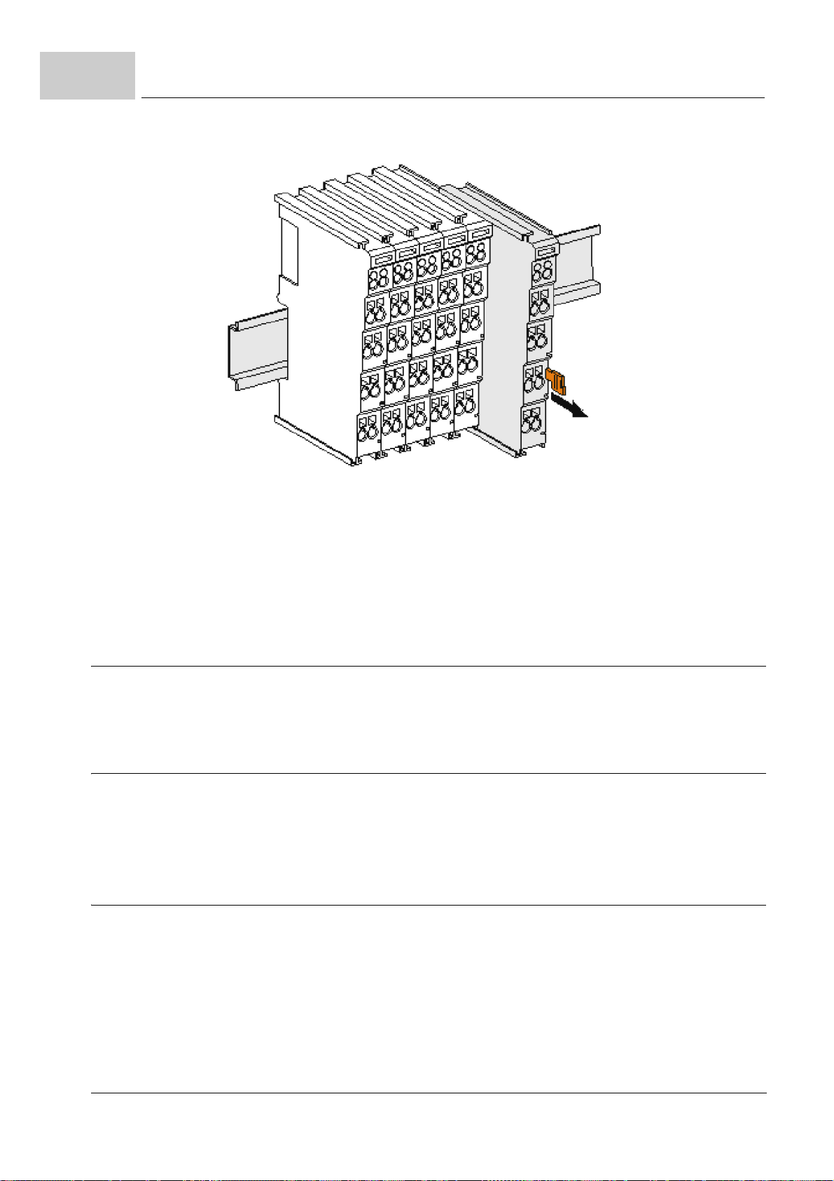
9.5
Storage conditions
Figure 16:
1 Carefully pull the orange-colored lug approximately 1 cm out of the disassembled ter-
minal, until it protrudes loosely. The lock with the
terminal, and the terminal can be pulled from the mounting rail without excessive force.
sp the released terminal with thumb and index finger simultaneous at the upper and
2 Gra
lower grooved housing surfaces and pull the terminal away from the mounting rail.
9.5 Storage conditions
Store the terminals in suitable packaging according to the storage conditions in
pendix D - Technical Data– from page 71 onward.
ZAp
9.6 Recommissioning
If you want to recommission the terminals, observe the information in "Storage Conditions" in ZAp
Then, carry out ZAss
9.7 Disposal
In order to dispose of the device, it must be removed and fully dismantled.
m Housing components (polycarbonate,
cycling.
m Metal parts can be sent for metal recycling.
m Electronic parts such as disk drives and cir
dance with national electronics scrap regulations.
mounting rail is now released for this
pendix D - Technical Data– from page 71 onward.
embly and Installation– from page 35 onward again.
polyamide (PA6.6)) are suitable for plastic re-
cuit boards must be disposed of in accor-
62
of 82
Operation Manual Safety I/O Terminals SI4000 / SO4000
Document no.: 5.08009.05 Baumüller Nürnberg GmbH

APPENDIX A - ABBREVIATIONS
CPU Central Processing Unit
DC Diagnostic Coverage
Diag Diagnostic LED
DIN Deutsches Institut für Normung
EMC Electromagnetic compatibility
EN European standard
FSoE Safety protocol „Safety over Ether-
HFT Hardware Failure Tolerance
I/O Input/Output
I/O bus Bus between b maXX safe PLC
LED Light-emitting diode
MTTF
PFD Probability of Failure on Demand
PFH Probability of Failure per Hour
PLC Process loop control, stored Pro-
RAM Random Access Memory
ROM Read Only Memory
SFF Safe Failure Fraction (Fraction of
SIL Safety Integrity Level
SW Software
e.V.
CAT“
and the modules right of the PLC
and/or power supply
Mean Time To Failure
d
gram Control, SPS
failures which lead to safe status)
Operation Manual Safety I/O Terminals SI4000 / SO4000
Document no.: 5.08009.05
63
of 82

A
64
of 82
Operation Manual Safety I/O Terminals SI4000 / SO4000
Document no.: 5.08009.05 Baumüller Nürnberg GmbH

This appendix lists all accessory items which are available from Baumüller Nürnberg
GmbH for the safety I/O terminals.
If you have enquiries or suggestions on the accessory items, the Baumüller product management will be glad to assist you.
B.1 List of all accessory items
At the moment there are no accessories available for the I/O terminals.
APPENDIX B - ACCESSORIES
Operation Manual Safety I/O Terminals SI4000 / SO4000
Document no.: 5.08009.05
65
of 82

B.1
List of all accessory items
66
of 82
Operation Manual Safety I/O Terminals SI4000 / SO4000
Document no.: 5.08009.05 Baumüller Nürnberg GmbH

The use of checklists serves documentation purposes and guides in the implementation
of a safety system. The checklists reproduced in Appendix C - Checklists serve to prevent
errors and must be processed carefully for every project. It is also required to make cop
ies of the printed checklists.
No claim is made that the checklists are complete. There may be additional requirements
depending on the specific plant.
C.1 Installation checklist
APPENDIX C - CHECKLISTS
-
Serial
no.
1 Installation
1.1 Has it been ensured that there are no short
1.2 Has it been ensured that the safety switch
1.3 Has a wiring inspection in accordance with
1.4 Are all connection plugs labelled according
1.5 Are the connection terminals loaded with
1.6 Has it been ensured that the insulation of
1.7 Has the reliability of all terminal connections
Requirement Fulfilled Remarks
circuits from the wiring of the input and out
put terminals?
devices have not been bypassed as a result
of wiring errors?
the installation plan been conducted
to their allocation?
the specified clamping torque?
the lines is not causing any faulty contacts?
been tested through mechanical tensile
loading?
Yes No
-
Operating Instructions Safety I/O Terminals SI4000 / SO4000
Dokument-Nr.: 5.08009.05
67
of 82

C.1
Installation checklist
Serial
no.
1.8 Has a visual inspection of the installed com-
1.9 Have the required installation spacings to
1.10 Do the components meet the environmental
1.11 Does the system fulfil the required type of
1.12 Is degree of pollution 2 complied with?
1.13 Is the system protected against corrosive
Date Name Signature
Requirement Fulfilled Remarks
Yes No
ponents been conducted?
other components been complied with?
conditions prevailing in the application?
protection?
substances?
68
of 82
Operating Instructions Safety I/O Terminals SI4000 / SO4000
Dokument-Nr.: 5.08009.05 Baumüller Nürnberg GmbH

C.2 Commissioning and validation checklist
Checklists
C
Serial
no.
2 Commissioning
2.1 Has it been ensured that all safe communi-
2.2 Has a complete function test been con-
2.3 Has the operating personnel been
Date Name Signature
Requirement Fulfilled Remarks
Yes No
cation participants of a system have a
ique safe device address? This also
un
applies to participants belonging to different
safety controls, if the controls are connected
to one another via gateways (such as ethernet).
ducted and documented?
instructed in the handling of the control system?
Operating Instructions Safety I/O Terminals SI4000 / SO4000
Dokument-Nr.: 5.08009.05
69
of 82

C.2
Commissioning and validation checklist
70
of 82
Operating Instructions Safety I/O Terminals SI4000 / SO4000
Dokument-Nr.: 5.08009.05 Baumüller Nürnberg GmbH

In this appendix, you will find the technical data for Baumüller Nürnberg GmbH's Safety I/O terminals.
D.1 Connection technology
Connection technology
Wiring Cage Clamp® spring-loaded system
Connection cross-section 0.08 mm² ... 2.5 mm², AWG 28-14, stranded wire, solid
Field bus connection depending on fieldbus
Power contacts up to 3 blade/spring contacts
Current load 10 A
Nominal voltage depends on bus terminal type
D.2 Connection values
APPENDIX D - TECHNICAL DATA
wire
Product name SI4000
Number of inputs 4
Number of outputs 0
Status display 4 (one green LED per output)
Response time
(read input / write to I/O bus)
Fault response time < watch dog time (adjustable from 5 ms to 100 ms)
Cable length between sensor and
terminal (unscreened line)
Cable length between sensor and
terminal (screened line)
Operating Instructions Safety I/O Terminals SI4000 / SO4000
typical: 4 ms
maximum: see fault response time
max. 100 m (at 0.75 mm² or 1 mm²)
max. 100 m (at 0.75 mm² or 1 mm²)
Dokument-Nr.: 5.08009.05
71
of 82

D.2
Connection values
Product name SI4000
Input process image 6 bytes
Output process image 6 bytes
SI4000 supply voltage 24 VDC (-15% / +20%)
Current consumption of the modular
electronics at 24 V (without current
consumption of sensors)
Current consumption from I/O-bus 4 channel occupied: typically 47 mA
Power dissipation of the terminal typically 540 mW
Electrical isolation (between the
channels)
Electrical isolation (between the
channels and the I/O bus)
Insulation voltage (between the
channels
common operating conditions)
Permissible contamination level Contamination level 2
Unacceptable operating conditions Safety terminals must not used under the following
and the I/O bus, under
4 channel occupied: typically 12 mA
0 channel occupied: typically 1 mA
0 channel occupied: typically 33 mA
no
yes
isolation checked with 500 VDC
(see chapter ZCleaning– on page 58)
operating conditions:
m under the influence of ionising radiation
m in corrosive environments
m in an environment that leads to unacceptable soil-
ing of the bus terminal
Shocks 15 g with pulse duration 11 ms in all three axes
Protection class IP20
Permitted operating environment control cabinet or terminal box with minimum protec-
tion class IP54 according to IEC 60529
Permissable installation position any
Approvals CE
Product name SO4000
Number of inputs 0
Number of outputs 4
Status display 4 (one green LED per output)
Output current per channel max. 500 mA, min. 20 mA per channel
Cable length between sensor and
terminal (unscreened line)
Fault response time < watch dog time
max. 100 m
72
of 82
Operating Instructions Safety I/O Terminals SI4000 / SO4000
Dokument-Nr.: 5.08009.05 Baumüller Nürnberg GmbH

Product name SO4000
Technical Data
D
Cable length between sensor and
terminal (screened line)
Wire cross section min. 0.75 mm²
Input process image 6 bytes
Output process image 6 bytes
SO4000 supply voltage 24 VDC (-15% / +20%)
Current consumption from I/O-bus max. 250 mA
Power dissipation of the terminal typically 2 W
Electrical isolation (between the
channels)
Electrical isolation (between the
channels and the I/O bus)
Insulation voltage (between the
channels and the I/O bus, under
mon operating conditions
com
Permissible contamination level Contamination level 2
Unacceptable operating conditions Safety terminals must not used under the following
)
max. 100 m
no
yes
insulation checked with 500 VDC
(see chapter ZCle
operating conditions:
er the influence of ionising radiation
m und
m in co
m in a
rrosive environments
n environment that leads to unacceptable soil-
ing of the bus terminal
aning– on page 58)
Vibration/shock resistance conforms to EN 60068-2-6 / EN 60068-2-27
Shocks 15 g with pulse duration 11 ms in all three axes
Protection class IP20
Permitted operating environment control cabinet or terminal box with minimum protec-
tion class IP54 according to IEC
Permissable installation position horizontal
Approvals CE
WARNING!
The operating conditions specified in the ta
time.
ble above may not be exceeded at any
60529
Operating Instructions Safety I/O Terminals SI4000 / SO4000
Dokument-Nr.: 5.08009.05
73
of 82

D.3
D.3 Operating conditions
D.3.1 Climatic properties
Operating conditions
Product SI4000
Permissible ambient temperature
(operation)
Permissible ambient temperature
(transport and storage)
Permissible relative air humidity 95 %, non-condensing
Climate class according to
60721-3-3
EN
Permissable air pressure (operation,
storage, transport)
Product SO4000
Permissible ambient temperature
(operation)
Permissible ambient temperature
(transport and storage)
Permissible relative air humidity 95 %, non-condensing
Climate class according to
60721-3-3
EN
0°C ... +55°C
-25°C ... +70°C
3K3
750 hPa to 1100 hPa
0°C ... +55°C
-25°C ... +70°C
3K3
Permissable air pressure (operation,
storage, transport)
D.3.2 Mechanical properties
Product SI4000
Material polycarbonate, polyamide (PA 6.6)
Dimensions (W x H x D) 12 mm x 100 mm x 68 mm
Mounting on 35 mm mounting rail (conforms to EN 50022) with
Attachable by double slot and key connection
Weight approx. 50 g
750 hPa to 1100 hPa
lock
74
of 82
Operating Instructions Safety I/O Terminals SI4000 / SO4000
Dokument-Nr.: 5.08009.05 Baumüller Nürnberg GmbH

Product SO4000
Material polycarbonate, polyamide (PA 6.6)
Dimensions (W x H x D) 24 mm x 100 mm x 68 mm
Mounting on 35 mm mounting rail (conforms to EN 50022) with
Attachable by double slot and key connection
Weight approx. 100 g
D.3.3 EMC properties
Product SI4000 and SO4000
EMC resistance burst conforms to EN 61000-6-2
ESD emission conforms to EN 61000-6-4
lock
Technical Data
D
Operating Instructions Safety I/O Terminals SI4000 / SO4000
Dokument-Nr.: 5.08009.05
75
of 82

D.3
Operating conditions
76
of 82
Operating Instructions Safety I/O Terminals SI4000 / SO4000
Dokument-Nr.: 5.08009.05 Baumüller Nürnberg GmbH

APPENDIX E - DECLARATION OF
In this section we provide general information about EC directives, the CE symbol and the
Declaration of Conformity.
E.1 What is an EC directive?
EC directives specify requirements. The directives are written by the relevant bodies within the EU (which used to be called the EC, and the EEC before that, hence the now illogical term EC directive), and are implemented by all the member countries of the EU in
national law. In this way the EC directives guarantee free trade within the EU.
An EC directive only contains essential minimum requirements. You will find detailed requirements in standards, to which references are made in the directive.
E.2 What the CE symbol indicates
a) The CE marking symbolizes conformity to all the obligations incumbent on manufacturers for the product by virtue of the Community directives providing for its affixing.
…
CONFORMITY
b) The CE marking affixed to industrial products symbolizes the fact that the natural or
legal person having affixed or be en responsible for the affixing of the said marking has
verified that the product conforms to all the Community total harmonization provisions
which apply to it and has been the subject of the appropriate conformity evaluation pro
cedures.
…
Council Decision 93/465/EEC, Annex I B. a) + c)
We affix the CE mark to the equipment and to the operating instructions as soon as we
have established that we have satisfied the requirements of the relevant directives.
I/O terminals supplied by the Baumüller Nürnberg GmbH are not concerned of the Low
Voltage Directive, because their operating voltage is less than 60
75
V AC. Therefore a declaration of conformity to 2006/95/EC (Low Voltage Directive)
cannot be issued.
Operation Manual Safety I/O Terminals SI4000 / SO4000
Document no.: 5.08009.05
V DC or less than
77
of 82
-

Definition of the term Declaration of Conformity
The electrical safety and function of the I/O terminals will be checked with the harmonized
standard EN
With specified application of this Baumüller equipment in your machinery, you can act on
the assumption that the equipment satisfies the requirements of 2006/42/EG (machinery
directive).
Therefore the equipment is developed and constructed in such a way, that the requirements of the harmonized standard EN 60204-1 can be met by the electrical installation.
I/O terminals supplied by the Baumüller Nürnberg GmbH satisfy the requirements of
2014/30/EU (EMC Directive) by satisfying the requirements of the harmonized standard
EN
61000-6-2 and EN 61000-6-4.
To enable you to market your machine within the EU, you must be in possession of the
following:
m Conformity mark (CE mark)
m Declaration(s) of Conformity regarding the directive(s) relevant to the machine
E.3 Definition of the term Declaration of Conformity
A Declaration of Conformity as defined by this operating instruction is a declaration that
the electrical equipment brought into circulation conforms to all the relevant fundamental
safety and health requirements.
61508, part 1-3.
By issuing the Declaration of Conformity in this section the Baumüller Nürnberg GmbH
declares that the equipment conforms to the relevant fundamental safety and health re
quirements resulting from the directives and standards which are listed in the Declaration
of Conformity.
E.4 Declaration of Conformity
-
78
of 82
Operation Manual Safety I/O Terminals SI4000 / SO4000
Document no.: 5.08009.05 Baumüller Nürnberg GmbH

Declaration of EC conformity Doc.-No.: 5.10067.01
Date: 2015-03-04
according to machinery directive 2006/42/EC
We the manufacturer: Baumüller Nürnberg GmbH
Ostendstraße 80-90
90482 Nürnberg, GERMANY
declare that our product
Name: Safety I/O Terminals
Type: SI4000, SO4000
Date of manufacture: 2015-03-04
was developed, constructed and manufactured according to the machinery directive 2006/42/EC.
Applied harmonized standards:
Authorized person for preserving relevant technical documents:
Name: Engelbert Meier, Baumüller Nürnberg GmbH
Address: Ostendstraße 80-90, 90482 Nürnberg, Germany
Notified body which has provided the EC type-Examination Certificate in accordance with the machinery directive mentioned above:
Name: TÜV Süd Product Service GmbH
Address: Ridlerstr. 65, 80339 München / Germany
Notified body number: 0123
Registration number: Z10 15 03 75013 001 (SI4000) and Z10 15 03 75013 003 (S04000)
The safety instructions in the manual must be observed. This product is designed for integration in a machine. The commissioning is not allowed until the entire machine, in which this product is integrated, is complying with the directives mentioned above.
Nürnberg / 2015-03-04
Location / Date
subject to change of this declaration of EC conformity without notice. Actual valid edition on request
Standard Title
EN 61508-1:2010 Functional safety of security-related electric, electronic and programmable electronic systems - Part 1:
General requirements
EN 61508-2:2010 Functional safety of security-related electric, electronic and programmable electronic systems - Part 2:
Requirements for electrical/electronic/programmable electronic safety-related systems
EN 61508-3:2010 Functional safety of security-related electric, electronic and programmable electronic systems - Part 3:
Software requirements
EN ISO 13849-1:2008 Safety of machinery – Safety-related parts of control systems –
Part 1: General principles for design
DIN EN 81-1:2000 (to the extent
to which they may be applicable)
Safety rules for the construction and installation of lifts - Part 1: Electric lifts
EN 13243:2004 (to the extent to
which they may be applicable)
Safety requirements for cableway installations designed to carry persons - Electrical equipment other
than for drive systems
DIN EN 61000-6-2:2006 Electromagnetic compatibility (EMC) - Part 6-2: Generic standards - Immunity for industrial environ-
ments
DIN EN 61000-6-4:2007 Electromagnetic compatibility (EMC) - Part 6-4: Generic standards - Emission standard for industrial
environments
Declaration of Conformity
E
Operation Manual Safety I/O Terminals SI4000 / SO4000
Document no.: 5.08009.05
79
of 82

Declaration of Conformity
80
of 82
Operation Manual Safety I/O Terminals SI4000 / SO4000
Document no.: 5.08009.05 Baumüller Nürnberg GmbH

Index
Numerics
2006/95/EC 77
A
Address setting 47
Appropriate use 15
C
C mounting rails 36
CE symbol 77
Certification 11
Checklists 67
Cleaning 58
Climatic properties 74
Configuration
SI4000 49
Conformity
Declaration 78
Connection technology 71
Control cabinet 36
Copyright 10
D
Declaration of Conformity 77
Decommissioning 61
Diagnostic Coverage (DC) 26
Diagnostic LEDs
SI4000 54
SO4000 56
Dimensions
SI4000 32
SO4000 33
Disassembly 61
Disposal 62
E
EC directive 77
EMC properties 75
F
Firefighting 21
Function test 59
M
Mean Time To Failure (MTTFd) 26
Mechanical properties 74
O
Operating personnel 18
P
Parameter overview
SI4000 48
SO4000 50
PE power contact 38
Personnel protective equipment 19
Pin assignment
SI4000 43
SO4000 45
Power supply 39
Preface 7
Probability of Failure on Demand (PFD) 25
Probability of Failure per Hour (PFH) 25
Protective equipment 17
Q
Qualified personnel 18
S
Safety 15
Safety aspects 15
Safety-related parameters 25
Service life 58
SI4000 11
SO4000 11
SO4000 Test pulses 46
T
Technical Data 71
Terms
Definition 11
Test pulses 46
U
Unacceptable operating conditions 72
G
General description
SI4000 29
SO4000 30
W
Waranty conditions 11
Wiring 39
H
Hardware Failure Tolerance 25
L
Limitation of liability 9
Low Voltage Directive 77
Operating Instructions Safety I/O Terminals SI4000 / SO4000
Dokument-Nr.: 5.08009.05
81
of 82

Stichwortverzeichnis
82
of 82
Operating Instructions Safety I/O Terminals SI4000 / SO4000
Dokument-Nr.: 5.08009.05 Baumüller Nürnberg GmbH


Baumüller Nürnberg GmbH Ostendstraße 80-90 90482 Nuremberg Tel: +49(0)911-5432-0 Fax: +49(0)911-5432-130
All the information in these Operating Instructions is non-binding customer information; it is subject to ongoing further development and is updated on a continuous basis
by our permanent change management system. Note that all the data/numbers/information that are quoted are current values at the time of printing.
This information is not legally binding for dimensioning, calculation and costing. Before using the information listed in these Operating Instructions as the basis for your own
calculations and/or applications, make sure that you have the latest most current information.
This means that we accept no resonsibility for the accuracy of the information.
www.baumueller.de
 Loading...