


Parameter manual
Language English
Translation
Document No. 5.12001.07
Part No. 442290
Status 15.11.2017
E
5.12001.07
b maXX BM3000 /
BM2500
Parameter manual
Version 01.13
Read the Operating Manual before starting any work!

Copyright The owner may produce an unrestricted num ber of copies of this Parameter manua l solely
for internal use. This Parameter manual may not be copied or reproduced, even in extract
form, for any other purpose.
Use and disclosure of the contents of this Parameter manual are not permitted.
Names or company symbols in this Parameter manual can be trademarks, the use of which
by third parties for their own purposes may infringe the rights of the owners.
Preliminary informationCaution: The following applie s if this document is identified as preliminary information:
This version contains preliminary technical information which the users of the devices an d
functions described are intended to receive in advance, in order to be able to make arrangements for any changes or functional enhancements that may be required.
This information should be considered to be provisional , as it has not yet been subjected to
the final Baumüller internal review process. In particular this information i s still subject to
change, so that no legal obligation can be deduced on the basis of this preliminary information. Baumüller accepts no liability for damages that may arise from this possibly erroneous
or incomplete version.
Should you detect or suspect errors of content and/or serious technical errors in this preliminary information, we ask you to contact the Baumüller support pe rson responsible for you
and inform us of your findings and comments so that they might be considered and possibly
incorporated when the preliminary information becomes finalized (reviewed by Baumüller).
The conditions noted in the following section under "Liability" do not apply in the case of preliminary information.
Obligation This Parameter manual is a part of the device/machine. This Parameter manual must be ac-
cessible to the operator at all times and be in a legible condition . Whe n the d evice/machine
is sold/relocated, this Parameter manual must be passed on together with the device/ma
chine by the owner.
After the device/machine is sold, this original and all copies must be handed over to the purchaser. After disposal or other end of service life, this original and all copies must be destroyed.
When this Parameter manual is handed over, the corresponding Operating Manuals with earlier issue dates become invalid.
Please note that specifications/data/information are the current values on the date of print-
ing. These specifications are not legally binding for measuring, computation and costing.
Baumüller Nürnberg GmbH reserves the right to change the technical data and operation of
Baumüller products within the framework of its own further development of the products.
However no guarantee can be provided regarding the freedom from errors of this Parameter
manual, unless otherwise described in the General Conditions for Sales and Supply.
-
Baumüller Nürnberg GmbH
Ostendstr. 80 - 90
90482 Nürnberg
Deutschland
Tel. +49 9 11 54 32 - 0
Fax: +49 9 11 54 32 - 1 30
E-Mail: mail@baumueller.de
Internet: www.baumueller.de

Table of Contents
1 General . . . . . . . . . . . . . . . . . . . . . . . . . . . . . . . . . . . . . . . . . . . . . . . . . . . . . . . . . . . . . . . . . 11
1.1 Information about the Parameter Manual . . . . . . . . . . . . . . . . . . . . . . . . . . . . . . . . . . 11
1.2 Explanation of Symbols . . . . . . . . . . . . . . . . . . . . . . . . . . . . . . . . . . . . . . . . . . . . . . . . 12
1.3 Limitation of Liability . . . . . . . . . . . . . . . . . . . . . . . . . . . . . . . . . . . . . . . . . . . . . . . . . . 13
1.4 Copyright . . . . . . . . . . . . . . . . . . . . . . . . . . . . . . . . . . . . . . . . . . . . . . . . . . . . . . . . . . . 13
1.5 Other Applicable Documents. . . . . . . . . . . . . . . . . . . . . . . . . . . . . . . . . . . . . . . . . . . . 14
1.6 Guarantee Conditions . . . . . . . . . . . . . . . . . . . . . . . . . . . . . . . . . . . . . . . . . . . . . . . . . 14
1.7 Customer service. . . . . . . . . . . . . . . . . . . . . . . . . . . . . . . . . . . . . . . . . . . . . . . . . . . . . 14
1.8 Terms used . . . . . . . . . . . . . . . . . . . . . . . . . . . . . . . . . . . . . . . . . . . . . . . . . . . . . . . . . 14
2 Commissioning BM25xx . . . . . . . . . . . . . . . . . . . . . . . . . . . . . . . . . . . . . . . . . . . . . . . . . . . 15
2.1 Safety information . . . . . . . . . . . . . . . . . . . . . . . . . . . . . . . . . . . . . . . . . . . . . . . . . . . . 16
2.2 Voltage test . . . . . . . . . . . . . . . . . . . . . . . . . . . . . . . . . . . . . . . . . . . . . . . . . . . . . . . . . 17
2.3 Requirements for the electrical supply. . . . . . . . . . . . . . . . . . . . . . . . . . . . . . . . . . . . . 17
2.4 Preparations . . . . . . . . . . . . . . . . . . . . . . . . . . . . . . . . . . . . . . . . . . . . . . . . . . . . . . . . 18
2.5 Communication via EtherCAT . . . . . . . . . . . . . . . . . . . . . . . . . . . . . . . . . . . . . . . . . . . 20
2.6 Switch-on sequence . . . . . . . . . . . . . . . . . . . . . . . . . . . . . . . . . . . . . . . . . . . . . . . . . . 25
2.7 Performing the commissioning . . . . . . . . . . . . . . . . . . . . . . . . . . . . . . . . . . . . . . . . . . 26
3 Commissioning BM3xxx . . . . . . . . . . . . . . . . . . . . . . . . . . . . . . . . . . . . . . . . . . . . . . . . . . . 45
3.1 Safety information . . . . . . . . . . . . . . . . . . . . . . . . . . . . . . . . . . . . . . . . . . . . . . . . . . . . 46
3.2 Voltage test . . . . . . . . . . . . . . . . . . . . . . . . . . . . . . . . . . . . . . . . . . . . . . . . . . . . . . . . . 47
3.3 Requirements for the electrical supply. . . . . . . . . . . . . . . . . . . . . . . . . . . . . . . . . . . . . 47
3.4 Preparations . . . . . . . . . . . . . . . . . . . . . . . . . . . . . . . . . . . . . . . . . . . . . . . . . . . . . . . . 48
3.4.1 Communication via the service cable . . . . . . . . . . . . . . . . . . . . . . . . . . . . . . . . . . . . 51
3.4.2 Communication via EtherCAT. . . . . . . . . . . . . . . . . . . . . . . . . . . . . . . . . . . . . . . . . . 52
3.5 Switch-on sequence . . . . . . . . . . . . . . . . . . . . . . . . . . . . . . . . . . . . . . . . . . . . . . . . . . 57
3.6 Performing the commissioning . . . . . . . . . . . . . . . . . . . . . . . . . . . . . . . . . . . . . . . . . . 58
4 Description of the Software Modules and Parameters. . . . . . . . . . . . . . . . . . . . . . . . . . . 77
4.1 Cycle times of the software modules. . . . . . . . . . . . . . . . . . . . . . . . . . . . . . . . . . . . . . 77
4.2 Structure of the parameter overviews . . . . . . . . . . . . . . . . . . . . . . . . . . . . . . . . . . . . . 78
4.3 System. . . . . . . . . . . . . . . . . . . . . . . . . . . . . . . . . . . . . . . . . . . . . . . . . . . . . . . . . . . . . 80
4.3.1 System control. . . . . . . . . . . . . . . . . . . . . . . . . . . . . . . . . . . . . . . . . . . . . . . . . . . . . . 80
4.3.1.1 Parameter overview. . . . . . . . . . . . . . . . . . . . . . . . . . . . . . . . . . . . . . . . . . . . . . . . . 80
4.3.1.2 Description of the Parameters. . . . . . . . . . . . . . . . . . . . . . . . . . . . . . . . . . . . . . . . . 81
4.3.2 Display. . . . . . . . . . . . . . . . . . . . . . . . . . . . . . . . . . . . . . . . . . . . . . . . . . . . . . . . . . . . 90
4.3.2.1 Parameter overview. . . . . . . . . . . . . . . . . . . . . . . . . . . . . . . . . . . . . . . . . . . . . . . . . 90
4.3.2.2 Description of the Parameters. . . . . . . . . . . . . . . . . . . . . . . . . . . . . . . . . . . . . . . . . 90
4.4 Configuration . . . . . . . . . . . . . . . . . . . . . . . . . . . . . . . . . . . . . . . . . . . . . . . . . . . . . . . . 91
4.4.1 Power unit . . . . . . . . . . . . . . . . . . . . . . . . . . . . . . . . . . . . . . . . . . . . . . . . . . . . . . . . . 91
4.4.1.1 ProDrive Power Unit . . . . . . . . . . . . . . . . . . . . . . . . . . . . . . . . . . . . . . . . . . . . . . . . 92
4.4.1.2 Parameter overview. . . . . . . . . . . . . . . . . . . . . . . . . . . . . . . . . . . . . . . . . . . . . . . . . 92
4.4.1.3 Description of the Parameters. . . . . . . . . . . . . . . . . . . . . . . . . . . . . . . . . . . . . . . . . 94
4.4.2 Motor. . . . . . . . . . . . . . . . . . . . . . . . . . . . . . . . . . . . . . . . . . . . . . . . . . . . . . . . . . . . 111
4.4.2.1 Motor Identification Plate. . . . . . . . . . . . . . . . . . . . . . . . . . . . . . . . . . . . . . . . . . . . 111
4.4.2.2 Torque limits . . . . . . . . . . . . . . . . . . . . . . . . . . . . . . . . . . . . . . . . . . . . . . . . . . . . . 111
4.4.2.3 Torque monitoring . . . . . . . . . . . . . . . . . . . . . . . . . . . . . . . . . . . . . . . . . . . . . . . . . 113
Parameter manual b maXX BM3000
Document no.: 5.12001.07
3
of 820

Table of Contents
4.4.2.4 Torque Threshold. . . . . . . . . . . . . . . . . . . . . . . . . . . . . . . . . . . . . . . . . . . . . . . . . . 113
4.4.2.5 Maximum permissible speed (electrical conditioned). . . . . . . . . . . . . . . . . . . . . . . 114
4.4.2.6 ProDrive Motor. . . . . . . . . . . . . . . . . . . . . . . . . . . . . . . . . . . . . . . . . . . . . . . . . . . . 115
4.4.2.7 Parameter overview motor. . . . . . . . . . . . . . . . . . . . . . . . . . . . . . . . . . . . . . . . . . . 115
4.4.2.8 Description of the Parameters . . . . . . . . . . . . . . . . . . . . . . . . . . . . . . . . . . . . . . . . 118
4.4.3 Synchronous Motor . . . . . . . . . . . . . . . . . . . . . . . . . . . . . . . . . . . . . . . . . . . . . . . . . 148
4.4.3.1 ProDrive Synchronous Motor. . . . . . . . . . . . . . . . . . . . . . . . . . . . . . . . . . . . . . . . . 148
4.4.4 Asynchronous Motor . . . . . . . . . . . . . . . . . . . . . . . . . . . . . . . . . . . . . . . . . . . . . . . . 149
4.4.4.1 ProDrive Asynchronous Motor . . . . . . . . . . . . . . . . . . . . . . . . . . . . . . . . . . . . . . . . 149
4.4.4.2 Lh-characteristic. . . . . . . . . . . . . . . . . . . . . . . . . . . . . . . . . . . . . . . . . . . . . . . . . . . 149
4.4.4.3 ProDrive Lh-characteristic . . . . . . . . . . . . . . . . . . . . . . . . . . . . . . . . . . . . . . . . . . . 151
4.4.4.4 Parameter overview Lh-characteristic . . . . . . . . . . . . . . . . . . . . . . . . . . . . . . . . . . 151
4.4.4.5 Description of the Lh-characteristic parameters. . . . . . . . . . . . . . . . . . . . . . . . . . . 152
4.4.5 Synchronous motor with interior permanent magnet. . . . . . . . . . . . . . . . . . . . . . . . 153
4.4.5.1 Control . . . . . . . . . . . . . . . . . . . . . . . . . . . . . . . . . . . . . . . . . . . . . . . . . . . . . . . . . . 153
4.4.5.2 Commissioning. . . . . . . . . . . . . . . . . . . . . . . . . . . . . . . . . . . . . . . . . . . . . . . . . . . . 154
4.4.5.3 Identification of the nonlinear parameters . . . . . . . . . . . . . . . . . . . . . . . . . . . . . . . 155
4.4.5.4 Field weakening at IPMSM. . . . . . . . . . . . . . . . . . . . . . . . . . . . . . . . . . . . . . . . . . . 155
4.4.5.5 Parameter overview . . . . . . . . . . . . . . . . . . . . . . . . . . . . . . . . . . . . . . . . . . . . . . . . 157
4.4.5.6 Description of the Parameters . . . . . . . . . . . . . . . . . . . . . . . . . . . . . . . . . . . . . . . . 158
4.4.6 Encoder . . . . . . . . . . . . . . . . . . . . . . . . . . . . . . . . . . . . . . . . . . . . . . . . . . . . . . . . . . 162
4.4.6.1 Encoder monitoring . . . . . . . . . . . . . . . . . . . . . . . . . . . . . . . . . . . . . . . . . . . . . . . . 163
4.4.6.2 ProDrive Encoder. . . . . . . . . . . . . . . . . . . . . . . . . . . . . . . . . . . . . . . . . . . . . . . . . . 166
4.4.6.3 Encoder optimization . . . . . . . . . . . . . . . . . . . . . . . . . . . . . . . . . . . . . . . . . . . . . . . 166
4.4.6.4 Encoder correction. . . . . . . . . . . . . . . . . . . . . . . . . . . . . . . . . . . . . . . . . . . . . . . . . 167
4.4.6.5 Encoder accuracy and excentricity. . . . . . . . . . . . . . . . . . . . . . . . . . . . . . . . . . . . . 170
4.4.6.6 Resolver synchronization. . . . . . . . . . . . . . . . . . . . . . . . . . . . . . . . . . . . . . . . . . . . 171
4.4.6.7 Parameter overview . . . . . . . . . . . . . . . . . . . . . . . . . . . . . . . . . . . . . . . . . . . . . . . . 172
4.4.6.8 Description of the Parameters . . . . . . . . . . . . . . . . . . . . . . . . . . . . . . . . . . . . . . . . 174
4.4.7 Autotuning of Current controller. . . . . . . . . . . . . . . . . . . . . . . . . . . . . . . . . . . . . . . . 199
4.4.7.1 ProDrive Autotuning of the Current controller . . . . . . . . . . . . . . . . . . . . . . . . . . . . 200
4.4.7.2 Parameter overview . . . . . . . . . . . . . . . . . . . . . . . . . . . . . . . . . . . . . . . . . . . . . . . . 200
4.4.7.3 Description of the Parameters . . . . . . . . . . . . . . . . . . . . . . . . . . . . . . . . . . . . . . . . 201
4.4.8 Autotuning of position / speed controller . . . . . . . . . . . . . . . . . . . . . . . . . . . . . . . . . 207
4.4.8.1 Ks Determination . . . . . . . . . . . . . . . . . . . . . . . . . . . . . . . . . . . . . . . . . . . . . . . . . . 207
4.4.8.2 ProDrive Ks Determination. . . . . . . . . . . . . . . . . . . . . . . . . . . . . . . . . . . . . . . . . . . 210
4.4.8.3 Parameter overview Ks measurement. . . . . . . . . . . . . . . . . . . . . . . . . . . . . . . . . . 210
4.4.8.4 Description of the Ks measurement parameters . . . . . . . . . . . . . . . . . . . . . . . . . . 211
4.4.9 Autotuning Asynchronous Motor . . . . . . . . . . . . . . . . . . . . . . . . . . . . . . . . . . . . . . . 215
4.4.9.1 Identification Lh characteristic . . . . . . . . . . . . . . . . . . . . . . . . . . . . . . . . . . . . . . . . 215
4.4.10 Digital Inputs . . . . . . . . . . . . . . . . . . . . . . . . . . . . . . . . . . . . . . . . . . . . . . . . . . . . . . 216
4.4.10.1 ProDrive Digital Inputs . . . . . . . . . . . . . . . . . . . . . . . . . . . . . . . . . . . . . . . . . . . . . . 216
4.4.10.2 Parameter overview . . . . . . . . . . . . . . . . . . . . . . . . . . . . . . . . . . . . . . . . . . . . . . . . 217
4.4.10.3 Parameter description . . . . . . . . . . . . . . . . . . . . . . . . . . . . . . . . . . . . . . . . . . . . . . 217
4.4.11 Digital Outputs . . . . . . . . . . . . . . . . . . . . . . . . . . . . . . . . . . . . . . . . . . . . . . . . . . . . . 222
4.4.11.1 ProDrive Digital Outputs. . . . . . . . . . . . . . . . . . . . . . . . . . . . . . . . . . . . . . . . . . . . . 222
4.4.11.2 Parameter overview . . . . . . . . . . . . . . . . . . . . . . . . . . . . . . . . . . . . . . . . . . . . . . . . 222
4.4.11.3 Description of the Parameters . . . . . . . . . . . . . . . . . . . . . . . . . . . . . . . . . . . . . . . . 223
4.4.12 Analog Inputs. . . . . . . . . . . . . . . . . . . . . . . . . . . . . . . . . . . . . . . . . . . . . . . . . . . . . . 226
4.4.12.1 Description of the Analog Inputs . . . . . . . . . . . . . . . . . . . . . . . . . . . . . . . . . . . . . . 226
4.4.12.2 ProDrive analog input. . . . . . . . . . . . . . . . . . . . . . . . . . . . . . . . . . . . . . . . . . . . . . . 228
4.4.12.3 Parameter overview . . . . . . . . . . . . . . . . . . . . . . . . . . . . . . . . . . . . . . . . . . . . . . . . 228
4.4.12.4 Description of the Parameters . . . . . . . . . . . . . . . . . . . . . . . . . . . . . . . . . . . . . . . . 228
4
of 820
Parameter manual b maXX BM3000
Document no.: 5.12001.07 Baumüller Nürnberg GmbH

Table of Contents
4.4.13 Analog Outputs . . . . . . . . . . . . . . . . . . . . . . . . . . . . . . . . . . . . . . . . . . . . . . . . . . . . 230
4.4.13.1 Description of the Analog Outputs . . . . . . . . . . . . . . . . . . . . . . . . . . . . . . . . . . . . . 230
4.4.13.2 ProDrive Analog Outputs . . . . . . . . . . . . . . . . . . . . . . . . . . . . . . . . . . . . . . . . . . . . 230
4.4.13.3 Parameter overview . . . . . . . . . . . . . . . . . . . . . . . . . . . . . . . . . . . . . . . . . . . . . . . . 231
4.4.13.4 Description of the Parameters . . . . . . . . . . . . . . . . . . . . . . . . . . . . . . . . . . . . . . . . 232
4.4.14 Filter . . . . . . . . . . . . . . . . . . . . . . . . . . . . . . . . . . . . . . . . . . . . . . . . . . . . . . . . . . . . . 236
4.4.14.1 ProDrive filter . . . . . . . . . . . . . . . . . . . . . . . . . . . . . . . . . . . . . . . . . . . . . . . . . . . . . 236
4.4.14.2 ProDrive Filter. . . . . . . . . . . . . . . . . . . . . . . . . . . . . . . . . . . . . . . . . . . . . . . . . . . . . 239
4.4.14.3 Parameter overview . . . . . . . . . . . . . . . . . . . . . . . . . . . . . . . . . . . . . . . . . . . . . . . . 239
4.4.14.4 Description of the Parameters . . . . . . . . . . . . . . . . . . . . . . . . . . . . . . . . . . . . . . . . 240
4.4.15 Fieldbus communication . . . . . . . . . . . . . . . . . . . . . . . . . . . . . . . . . . . . . . . . . . . . . 244
4.4.15.1 Parameter IDs for the Real Time Lists . . . . . . . . . . . . . . . . . . . . . . . . . . . . . . . . . . 247
4.4.15.2 Access Counter for each Real Time List . . . . . . . . . . . . . . . . . . . . . . . . . . . . . . . . 247
4.4.15.3 Parameter overview . . . . . . . . . . . . . . . . . . . . . . . . . . . . . . . . . . . . . . . . . . . . . . . . 247
4.4.15.4 Description of the Parameters . . . . . . . . . . . . . . . . . . . . . . . . . . . . . . . . . . . . . . . . 248
4.4.16 Measuring encoder function. . . . . . . . . . . . . . . . . . . . . . . . . . . . . . . . . . . . . . . . . . . 256
4.4.16.1 ProDrive Measuring Encoder . . . . . . . . . . . . . . . . . . . . . . . . . . . . . . . . . . . . . . . . . 258
4.4.16.2 Parameter overview . . . . . . . . . . . . . . . . . . . . . . . . . . . . . . . . . . . . . . . . . . . . . . . . 258
4.4.16.3 Description of the Parameters . . . . . . . . . . . . . . . . . . . . . . . . . . . . . . . . . . . . . . . . 259
4.4.17 Freely programmable PID controller . . . . . . . . . . . . . . . . . . . . . . . . . . . . . . . . . . . . 270
4.4.17.1 Parameter overview . . . . . . . . . . . . . . . . . . . . . . . . . . . . . . . . . . . . . . . . . . . . . . . . 271
4.4.17.2 Description of the Parameters . . . . . . . . . . . . . . . . . . . . . . . . . . . . . . . . . . . . . . . . 273
4.4.18 Master-Slave Torque Coupling . . . . . . . . . . . . . . . . . . . . . . . . . . . . . . . . . . . . . . . . 280
4.4.18.1 Parameter overview . . . . . . . . . . . . . . . . . . . . . . . . . . . . . . . . . . . . . . . . . . . . . . . . 284
4.4.18.2 Description of the Parameters . . . . . . . . . . . . . . . . . . . . . . . . . . . . . . . . . . . . . . . . 285
4.4.19 Friction compensation . . . . . . . . . . . . . . . . . . . . . . . . . . . . . . . . . . . . . . . . . . . . . . . 291
4.4.19.1 Description of the friction compensation. . . . . . . . . . . . . . . . . . . . . . . . . . . . . . . . . 291
4.4.19.2 Identification of the friction torque curve. . . . . . . . . . . . . . . . . . . . . . . . . . . . . . . . . 294
4.4.19.3 Parameter overview . . . . . . . . . . . . . . . . . . . . . . . . . . . . . . . . . . . . . . . . . . . . . . . . 294
4.4.19.4 Description of the Parameters . . . . . . . . . . . . . . . . . . . . . . . . . . . . . . . . . . . . . . . . 295
4.4.20 Synchronization . . . . . . . . . . . . . . . . . . . . . . . . . . . . . . . . . . . . . . . . . . . . . . . . . . . . 298
4.4.20.1 Parameter overview . . . . . . . . . . . . . . . . . . . . . . . . . . . . . . . . . . . . . . . . . . . . . . . . 298
4.4.20.2 Description of the Parameters . . . . . . . . . . . . . . . . . . . . . . . . . . . . . . . . . . . . . . . . 298
4.4.21 Configurable status word . . . . . . . . . . . . . . . . . . . . . . . . . . . . . . . . . . . . . . . . . . . . 301
4.4.21.1 Parameter overview . . . . . . . . . . . . . . . . . . . . . . . . . . . . . . . . . . . . . . . . . . . . . . . . 302
4.4.21.2 Description of the Parameters . . . . . . . . . . . . . . . . . . . . . . . . . . . . . . . . . . . . . . . . 303
4.4.22 SoftDrivePLC . . . . . . . . . . . . . . . . . . . . . . . . . . . . . . . . . . . . . . . . . . . . . . . . . . . . . . 307
4.4.22.1 Overview SoftDrivePLC . . . . . . . . . . . . . . . . . . . . . . . . . . . . . . . . . . . . . . . . . . . . . 307
4.4.22.2 Function . . . . . . . . . . . . . . . . . . . . . . . . . . . . . . . . . . . . . . . . . . . . . . . . . . . . . . . . . 307
4.4.22.3 Limitations . . . . . . . . . . . . . . . . . . . . . . . . . . . . . . . . . . . . . . . . . . . . . . . . . . . . . . . 308
4.4.22.4 Tasks . . . . . . . . . . . . . . . . . . . . . . . . . . . . . . . . . . . . . . . . . . . . . . . . . . . . . . . . . . . 309
4.4.22.5 Programming interface . . . . . . . . . . . . . . . . . . . . . . . . . . . . . . . . . . . . . . . . . . . . . . 309
4.4.22.6 Parameter overview . . . . . . . . . . . . . . . . . . . . . . . . . . . . . . . . . . . . . . . . . . . . . . . . 310
4.4.22.7 Description of the Parameters . . . . . . . . . . . . . . . . . . . . . . . . . . . . . . . . . . . . . . . . 311
4.4.23 DS402 Factor Group . . . . . . . . . . . . . . . . . . . . . . . . . . . . . . . . . . . . . . . . . . . . . . . . 318
4.4.23.1 General information . . . . . . . . . . . . . . . . . . . . . . . . . . . . . . . . . . . . . . . . . . . . . . . . 318
4.4.23.2 ProDrive DS402 . . . . . . . . . . . . . . . . . . . . . . . . . . . . . . . . . . . . . . . . . . . . . . . . . . . 323
4.4.23.3 Parameter overview . . . . . . . . . . . . . . . . . . . . . . . . . . . . . . . . . . . . . . . . . . . . . . . . 323
4.4.23.4 Description of the Parameter . . . . . . . . . . . . . . . . . . . . . . . . . . . . . . . . . . . . . . . . . 325
4.5 Management. . . . . . . . . . . . . . . . . . . . . . . . . . . . . . . . . . . . . . . . . . . . . . . . . . . . . . . . 330
4.5.1 Drive management. . . . . . . . . . . . . . . . . . . . . . . . . . . . . . . . . . . . . . . . . . . . . . . . . . 330
4.5.1.1 Parameter overview . . . . . . . . . . . . . . . . . . . . . . . . . . . . . . . . . . . . . . . . . . . . . . . . 340
4.5.1.2 Description of the Parameters . . . . . . . . . . . . . . . . . . . . . . . . . . . . . . . . . . . . . . . . 341
Parameter manual b maXX BM3000
Document no.: 5.12001.07
5
of 820

Table of Contents
4.5.2 Data Set Management. . . . . . . . . . . . . . . . . . . . . . . . . . . . . . . . . . . . . . . . . . . . . . . 362
4.5.2.1 General. . . . . . . . . . . . . . . . . . . . . . . . . . . . . . . . . . . . . . . . . . . . . . . . . . . . . . . . . . 362
4.5.2.2 Command interface . . . . . . . . . . . . . . . . . . . . . . . . . . . . . . . . . . . . . . . . . . . . . . . . 362
4.5.2.3 Organization of the parameters in the data sets . . . . . . . . . . . . . . . . . . . . . . . . . . 363
4.5.2.4 Delivered state . . . . . . . . . . . . . . . . . . . . . . . . . . . . . . . . . . . . . . . . . . . . . . . . . . . . 364
4.5.2.5 Switch-On behavior . . . . . . . . . . . . . . . . . . . . . . . . . . . . . . . . . . . . . . . . . . . . . . . . 364
4.5.2.6 Changing, loading, copying and storing parameters . . . . . . . . . . . . . . . . . . . . . . . 364
4.5.2.7 Identification of parameter set and data sets . . . . . . . . . . . . . . . . . . . . . . . . . . . . . 364
4.5.2.8 Functions of the Data Set Management System . . . . . . . . . . . . . . . . . . . . . . . . . . 365
4.5.2.9 Data Set Commands and Possible Error Messages . . . . . . . . . . . . . . . . . . . . . . . 366
4.5.2.10 Changeover to Data Set 1 to 7. . . . . . . . . . . . . . . . . . . . . . . . . . . . . . . . . . . . . . . . 368
4.5.2.11 Overview of the Data Set Management Commands . . . . . . . . . . . . . . . . . . . . . . . 368
4.5.2.12 Parameter overview . . . . . . . . . . . . . . . . . . . . . . . . . . . . . . . . . . . . . . . . . . . . . . . . 369
4.5.2.13 Description of the Parameters . . . . . . . . . . . . . . . . . . . . . . . . . . . . . . . . . . . . . . . . 370
4.5.3 Brake management . . . . . . . . . . . . . . . . . . . . . . . . . . . . . . . . . . . . . . . . . . . . . . . . . 374
4.5.3.1 Description of the Brake Management System . . . . . . . . . . . . . . . . . . . . . . . . . . . 374
4.5.3.2 Brake watchdog . . . . . . . . . . . . . . . . . . . . . . . . . . . . . . . . . . . . . . . . . . . . . . . . . . . 379
4.5.3.3 ProDrive Brake Management. . . . . . . . . . . . . . . . . . . . . . . . . . . . . . . . . . . . . . . . . 380
4.5.3.4 Parameter overview . . . . . . . . . . . . . . . . . . . . . . . . . . . . . . . . . . . . . . . . . . . . . . . . 380
4.5.3.5 Description of the Parameters . . . . . . . . . . . . . . . . . . . . . . . . . . . . . . . . . . . . . . . . 381
4.5.4 Error Management. . . . . . . . . . . . . . . . . . . . . . . . . . . . . . . . . . . . . . . . . . . . . . . . . . 386
4.5.4.1 Parameter overview . . . . . . . . . . . . . . . . . . . . . . . . . . . . . . . . . . . . . . . . . . . . . . . . 386
4.5.4.2 Description of the Parameters . . . . . . . . . . . . . . . . . . . . . . . . . . . . . . . . . . . . . . . . 387
4.5.5 Signal Bus . . . . . . . . . . . . . . . . . . . . . . . . . . . . . . . . . . . . . . . . . . . . . . . . . . . . . . . . 391
4.5.5.1 Messages on the Signal Bus . . . . . . . . . . . . . . . . . . . . . . . . . . . . . . . . . . . . . . . . . 391
4.5.5.2 Supply Ready for use. . . . . . . . . . . . . . . . . . . . . . . . . . . . . . . . . . . . . . . . . . . . . . . 391
4.5.5.3 Chopper Resistor On . . . . . . . . . . . . . . . . . . . . . . . . . . . . . . . . . . . . . . . . . . . . . . . 391
4.5.5.4 ProDrive Signal bus . . . . . . . . . . . . . . . . . . . . . . . . . . . . . . . . . . . . . . . . . . . . . . . . 392
4.5.5.5 Parameter overview . . . . . . . . . . . . . . . . . . . . . . . . . . . . . . . . . . . . . . . . . . . . . . . . 392
4.5.5.6 Description of the Parameters . . . . . . . . . . . . . . . . . . . . . . . . . . . . . . . . . . . . . . . . 392
4.5.6 Set Value Manager . . . . . . . . . . . . . . . . . . . . . . . . . . . . . . . . . . . . . . . . . . . . . . . . . 394
4.5.6.1 Parameter overview . . . . . . . . . . . . . . . . . . . . . . . . . . . . . . . . . . . . . . . . . . . . . . . . 395
4.5.6.2 Description of the Parameters . . . . . . . . . . . . . . . . . . . . . . . . . . . . . . . . . . . . . . . . 395
4.6 Set Value Generators. . . . . . . . . . . . . . . . . . . . . . . . . . . . . . . . . . . . . . . . . . . . . . . . . 399
4.6.1 Ramp function generator . . . . . . . . . . . . . . . . . . . . . . . . . . . . . . . . . . . . . . . . . . . . . 399
4.6.1.1 Optional interpolation of the ramp function generator input set value . . . . . . . . . . 403
4.6.1.2 ProDrive Ramp Function Generator. . . . . . . . . . . . . . . . . . . . . . . . . . . . . . . . . . . . 405
4.6.1.3 Parameter overview . . . . . . . . . . . . . . . . . . . . . . . . . . . . . . . . . . . . . . . . . . . . . . . . 406
4.6.1.4 Description of the Parameters . . . . . . . . . . . . . . . . . . . . . . . . . . . . . . . . . . . . . . . . 408
4.6.2 Set Value Generator . . . . . . . . . . . . . . . . . . . . . . . . . . . . . . . . . . . . . . . . . . . . . . . . 417
4.6.2.1 Parameter overview . . . . . . . . . . . . . . . . . . . . . . . . . . . . . . . . . . . . . . . . . . . . . . . . 417
4.6.2.2 Description of the Parameters . . . . . . . . . . . . . . . . . . . . . . . . . . . . . . . . . . . . . . . . 418
4.6.3 Error reaction controlled stop. . . . . . . . . . . . . . . . . . . . . . . . . . . . . . . . . . . . . . . . . . 421
4.6.4 Error Reaction Return Motion . . . . . . . . . . . . . . . . . . . . . . . . . . . . . . . . . . . . . . . . . 422
4.6.4.1 Parameter Overview. . . . . . . . . . . . . . . . . . . . . . . . . . . . . . . . . . . . . . . . . . . . . . . . 422
4.6.4.2 Description of the Parameters . . . . . . . . . . . . . . . . . . . . . . . . . . . . . . . . . . . . . . . . 423
4.6.5 Cam generator. . . . . . . . . . . . . . . . . . . . . . . . . . . . . . . . . . . . . . . . . . . . . . . . . . . . . 426
4.6.5.1 Time control via the table index . . . . . . . . . . . . . . . . . . . . . . . . . . . . . . . . . . . . . . . 426
4.6.5.2 Time control with virtual master axis . . . . . . . . . . . . . . . . . . . . . . . . . . . . . . . . . . . 426
4.6.5.3 Parameter-controlled processing . . . . . . . . . . . . . . . . . . . . . . . . . . . . . . . . . . . . . . 427
4.6.5.4 Setting options of cam generator . . . . . . . . . . . . . . . . . . . . . . . . . . . . . . . . . . . . . . 428
4.6.5.5 State machine of the cam generator . . . . . . . . . . . . . . . . . . . . . . . . . . . . . . . . . . . 431
4.6.5.6 Limiting of output value . . . . . . . . . . . . . . . . . . . . . . . . . . . . . . . . . . . . . . . . . . . . . 432
6
of 820
Parameter manual b maXX BM3000
Document no.: 5.12001.07 Baumüller Nürnberg GmbH

Table of Contents
4.6.5.7 Handling the cam data. . . . . . . . . . . . . . . . . . . . . . . . . . . . . . . . . . . . . . . . . . . . . . 432
4.6.5.8 Parameter Overview . . . . . . . . . . . . . . . . . . . . . . . . . . . . . . . . . . . . . . . . . . . . . . . 433
4.6.5.9 Description of the Parameters. . . . . . . . . . . . . . . . . . . . . . . . . . . . . . . . . . . . . . . . 433
4.6.6 Motor potentiometer . . . . . . . . . . . . . . . . . . . . . . . . . . . . . . . . . . . . . . . . . . . . . . . . 437
4.6.6.1 Parameter Overview . . . . . . . . . . . . . . . . . . . . . . . . . . . . . . . . . . . . . . . . . . . . . . . 437
4.6.6.2 Description of the Parameters. . . . . . . . . . . . . . . . . . . . . . . . . . . . . . . . . . . . . . . . 438
4.7 Controllers . . . . . . . . . . . . . . . . . . . . . . . . . . . . . . . . . . . . . . . . . . . . . . . . . . . . . . . . . 441
4.7.1 Position / Speed Controller . . . . . . . . . . . . . . . . . . . . . . . . . . . . . . . . . . . . . . . . . . . 441
4.7.1.1 The factor Ks . . . . . . . . . . . . . . . . . . . . . . . . . . . . . . . . . . . . . . . . . . . . . . . . . . . . . 446
4.7.1.2 Position / speed controller adaption. . . . . . . . . . . . . . . . . . . . . . . . . . . . . . . . . . . . 447
4.7.1.3 Cyclical Ks adaption . . . . . . . . . . . . . . . . . . . . . . . . . . . . . . . . . . . . . . . . . . . . . . . 448
4.7.1.4 ProDrive Position / Speed Controller. . . . . . . . . . . . . . . . . . . . . . . . . . . . . . . . . . . 449
4.7.1.5 Parameter Overview of Position / Speed Controller . . . . . . . . . . . . . . . . . . . . . . . 451
4.7.1.6 Description of the Parameters. . . . . . . . . . . . . . . . . . . . . . . . . . . . . . . . . . . . . . . . 453
4.7.2 Current Controller . . . . . . . . . . . . . . . . . . . . . . . . . . . . . . . . . . . . . . . . . . . . . . . . . . 469
4.7.2.1 Current Prediction . . . . . . . . . . . . . . . . . . . . . . . . . . . . . . . . . . . . . . . . . . . . . . . . . 469
4.7.2.2 Dead Time Compensation. . . . . . . . . . . . . . . . . . . . . . . . . . . . . . . . . . . . . . . . . . . 469
4.7.2.3 Torque Current Limiting. . . . . . . . . . . . . . . . . . . . . . . . . . . . . . . . . . . . . . . . . . . . . 470
4.7.2.4 Feedforward. . . . . . . . . . . . . . . . . . . . . . . . . . . . . . . . . . . . . . . . . . . . . . . . . . . . . . 477
4.7.2.5 Current controller adaption . . . . . . . . . . . . . . . . . . . . . . . . . . . . . . . . . . . . . . . . . . 477
4.7.2.6 Pulse Width Modulation. . . . . . . . . . . . . . . . . . . . . . . . . . . . . . . . . . . . . . . . . . . . . 478
4.7.2.7 ProDrive Current Controller . . . . . . . . . . . . . . . . . . . . . . . . . . . . . . . . . . . . . . . . . . 479
4.7.2.8 Overview of Current Controller Parameters. . . . . . . . . . . . . . . . . . . . . . . . . . . . . . 481
4.7.2.9 Description of Current Controller Parameters . . . . . . . . . . . . . . . . . . . . . . . . . . . . 482
4.7.3 DC link controller. . . . . . . . . . . . . . . . . . . . . . . . . . . . . . . . . . . . . . . . . . . . . . . . . . . 490
4.7.3.1 Description of the DC link controller . . . . . . . . . . . . . . . . . . . . . . . . . . . . . . . . . . . 490
4.7.3.2 ProDrive DC link controller . . . . . . . . . . . . . . . . . . . . . . . . . . . . . . . . . . . . . . . . . . 490
4.7.3.3 Reactive current brakes. . . . . . . . . . . . . . . . . . . . . . . . . . . . . . . . . . . . . . . . . . . . . 490
4.7.3.4 Short circuit brake . . . . . . . . . . . . . . . . . . . . . . . . . . . . . . . . . . . . . . . . . . . . . . . . . 491
4.7.3.5 Parameter Overview of the DC link controller . . . . . . . . . . . . . . . . . . . . . . . . . . . . 491
4.7.3.6 Description of the DC link controller parameter. . . . . . . . . . . . . . . . . . . . . . . . . . . 492
4.7.4 Field weakening controller. . . . . . . . . . . . . . . . . . . . . . . . . . . . . . . . . . . . . . . . . . . . 494
4.7.4.1 Breakdown torque . . . . . . . . . . . . . . . . . . . . . . . . . . . . . . . . . . . . . . . . . . . . . . . . . 498
4.7.4.2 Parameter overview. . . . . . . . . . . . . . . . . . . . . . . . . . . . . . . . . . . . . . . . . . . . . . . . 501
4.7.4.3 Description of the Field Weakening parameters . . . . . . . . . . . . . . . . . . . . . . . . . . 502
4.7.5 Two-level controller. . . . . . . . . . . . . . . . . . . . . . . . . . . . . . . . . . . . . . . . . . . . . . . . . 506
4.7.5.1 General . . . . . . . . . . . . . . . . . . . . . . . . . . . . . . . . . . . . . . . . . . . . . . . . . . . . . . . . . 506
4.7.5.2 Two-level controller with absolute thre sh old s . . . . . . . . . . . . . . . . . . . . . . . . . . . . 507
4.7.5.3 Two-level controller with relative thre sh old s . . . . . . . . . . . . . . . . . . . . . . . . . . . . . 508
4.7.5.4 Combination of the operating modes absolute and relative thresholds. . . . . . . . . 508
4.7.5.5 Sign-independent monitoring. . . . . . . . . . . . . . . . . . . . . . . . . . . . . . . . . . . . . . . . . 510
4.7.5.6 Linking of the controller output with the target parameter . . . . . . . . . . . . . . . . . . . 510
4.7.5.7 Parameter Overview of the Two-level Controller. . . . . . . . . . . . . . . . . . . . . . . . . . 511
4.7.5.8 Description of the Two-level Controller Parameter with absolute Thresholds. . . . 512
4.7.5.9 Description of the Two-level Controller Parameter with relative and absolute Thresholds
514
4.7.6 Flux controller . . . . . . . . . . . . . . . . . . . . . . . . . . . . . . . . . . . . . . . . . . . . . . . . . . . . . 518
4.7.6.1 ProDrive Flux controller. . . . . . . . . . . . . . . . . . . . . . . . . . . . . . . . . . . . . . . . . . . . . 518
4.7.6.2 Parameter Overview of the Flux Controller . . . . . . . . . . . . . . . . . . . . . . . . . . . . . . 518
4.7.6.3 Description of the Flux Controller parameters. . . . . . . . . . . . . . . . . . . . . . . . . . . . 519
4.7.7 Controller adaptations. . . . . . . . . . . . . . . . . . . . . . . . . . . . . . . . . . . . . . . . . . . . . . . 520
4.7.7.1 Parameter Overview of the Controller Adaptations. . . . . . . . . . . . . . . . . . . . . . . . 521
4.7.7.2 Description of the Controller Adaptations parameters. . . . . . . . . . . . . . . . . . . . . . 521
4.7.7.3 Adaption EMF feed forward. . . . . . . . . . . . . . . . . . . . . . . . . . . . . . . . . . . . . . . . . . 523
Parameter manual b maXX BM3000
Document no.: 5.12001.07
7
of 820

Table of Contents
4.7.7.4 Adaption torque monitoring . . . . . . . . . . . . . . . . . . . . . . . . . . . . . . . . . . . . . . . . . . 524
4.7.7.5 Ks adaption . . . . . . . . . . . . . . . . . . . . . . . . . . . . . . . . . . . . . . . . . . . . . . . . . . . . . . 525
4.7.7.6 Adaption of the Saturation . . . . . . . . . . . . . . . . . . . . . . . . . . . . . . . . . . . . . . . . . . . 526
4.7.7.7 Compensation dead time voltages. . . . . . . . . . . . . . . . . . . . . . . . . . . . . . . . . . . . . 527
4.7.7.8 Temperature adaption motor resistances. . . . . . . . . . . . . . . . . . . . . . . . . . . . . . . . 527
4.7.7.9 Temperature adaption slip frequency. . . . . . . . . . . . . . . . . . . . . . . . . . . . . . . . . . . 527
4.8 Operating Modes . . . . . . . . . . . . . . . . . . . . . . . . . . . . . . . . . . . . . . . . . . . . . . . . . . . . 530
4.8.1 Operating Modes general . . . . . . . . . . . . . . . . . . . . . . . . . . . . . . . . . . . . . . . . . . . . 530
4.8.1.1 Moving to positive stop command . . . . . . . . . . . . . . . . . . . . . . . . . . . . . . . . . . . . . 531
4.8.1.2 ProDrive general parameters. . . . . . . . . . . . . . . . . . . . . . . . . . . . . . . . . . . . . . . . . 534
4.8.1.3 Parameter overview . . . . . . . . . . . . . . . . . . . . . . . . . . . . . . . . . . . . . . . . . . . . . . . . 534
4.8.1.4 Description of the Parameters . . . . . . . . . . . . . . . . . . . . . . . . . . . . . . . . . . . . . . . . 535
4.8.2 Target Position Setting (Positioning) Mode . . . . . . . . . . . . . . . . . . . . . . . . . . . . . . . 549
4.8.2.1 Controlling the Positioning . . . . . . . . . . . . . . . . . . . . . . . . . . . . . . . . . . . . . . . . . . . 549
4.8.2.2 Positioning Data. . . . . . . . . . . . . . . . . . . . . . . . . . . . . . . . . . . . . . . . . . . . . . . . . . . 550
4.8.2.3 Bits in the Control Word / Status Word. . . . . . . . . . . . . . . . . . . . . . . . . . . . . . . . . . 551
4.8.2.4 Actions on the Rising Edge of "New Set Value". . . . . . . . . . . . . . . . . . . . . . . . . . . 552
4.8.2.5 Sequence of Events for Positioning Handshake with "Single Set Value". . . . . . . . 552
4.8.2.6 Sequence of Events for Handshake with “Set of Set Values” . . . . . . . . . . . . . . . . 554
4.8.2.7 Hardware limit switches . . . . . . . . . . . . . . . . . . . . . . . . . . . . . . . . . . . . . . . . . . . . . 555
4.8.2.8 Software Limit Switches. . . . . . . . . . . . . . . . . . . . . . . . . . . . . . . . . . . . . . . . . . . . . 557
4.8.2.9 Target Specifications . . . . . . . . . . . . . . . . . . . . . . . . . . . . . . . . . . . . . . . . . . . . . . . 557
4.8.2.10 Change of Operating Mode to Positioning . . . . . . . . . . . . . . . . . . . . . . . . . . . . . . . 558
4.8.2.11 Halting a Running Positioning Task . . . . . . . . . . . . . . . . . . . . . . . . . . . . . . . . . . . . 558
4.8.2.12 Aborting a Running Positioning Task. . . . . . . . . . . . . . . . . . . . . . . . . . . . . . . . . . . 559
4.8.2.13 Set Value Profiles. . . . . . . . . . . . . . . . . . . . . . . . . . . . . . . . . . . . . . . . . . . . . . . . . . 559
4.8.2.14 Comparison of Motion Profiles for Positioning . . . . . . . . . . . . . . . . . . . . . . . . . . . . 560
4.8.2.15 Control by Means of the "Start Positioning" Method . . . . . . . . . . . . . . . . . . . . . . . 562
4.8.2.16 Parameter overview . . . . . . . . . . . . . . . . . . . . . . . . . . . . . . . . . . . . . . . . . . . . . . . . 566
4.8.2.17 Description of the Parameters . . . . . . . . . . . . . . . . . . . . . . . . . . . . . . . . . . . . . . . . 567
4.8.3 Operating mode Homing . . . . . . . . . . . . . . . . . . . . . . . . . . . . . . . . . . . . . . . . . . . . . 583
4.8.3.1 Procedure of a homing under consideration of Zero pulse or Zero angle . . . . . . . 583
4.8.3.2 Shifting the zero angle . . . . . . . . . . . . . . . . . . . . . . . . . . . . . . . . . . . . . . . . . . . . . . 584
4.8.3.3 Maximum distance for zero pulse detection. . . . . . . . . . . . . . . . . . . . . . . . . . . . . . 584
4.8.3.4 Procedure of a Homing to switch only . . . . . . . . . . . . . . . . . . . . . . . . . . . . . . . . . . 584
4.8.3.5 Homing without setting the home position . . . . . . . . . . . . . . . . . . . . . . . . . . . . . . . 585
4.8.3.6 Automatic setting of the absolute value offset at homing. . . . . . . . . . . . . . . . . . . . 586
4.8.3.7 Notes . . . . . . . . . . . . . . . . . . . . . . . . . . . . . . . . . . . . . . . . . . . . . . . . . . . . . . . . . . . 586
4.8.3.8 Homing Method 1 (neg. limit switch) . . . . . . . . . . . . . . . . . . . . . . . . . . . . . . . . . . . 587
4.8.3.9 Homing Method 2 (pos. limit switch) . . . . . . . . . . . . . . . . . . . . . . . . . . . . . . . . . . . 587
4.8.3.10 Homing Methods 3 and 4 (pos. zero point changeover switch). . . . . . . . . . . . . . . 588
4.8.3.11 Homing Methods 5 and 6 (neg. zero point changeover switch). . . . . . . . . . . . . . . 589
4.8.3.12 Homing Methods 7 to 14 (Reference Switch). . . . . . . . . . . . . . . . . . . . . . . . . . . . . 590
4.8.3.13 Homing Methods 15 and 16 (reserved) . . . . . . . . . . . . . . . . . . . . . . . . . . . . . . . . . 591
4.8.3.14 Homing Methods 17 to 30 (without zero pulse or zero angle) . . . . . . . . . . . . . . . . 591
4.8.3.15 Homing Methods 31 and 32 (reserved) . . . . . . . . . . . . . . . . . . . . . . . . . . . . . . . . . 592
4.8.3.16 Homing Methods 33 and 34 (zero pulse only) . . . . . . . . . . . . . . . . . . . . . . . . . . . . 592
4.8.3.17 Homing Method 35 (set home position only) . . . . . . . . . . . . . . . . . . . . . . . . . . . . . 593
4.8.3.18 Manufacturer specific homing methods . . . . . . . . . . . . . . . . . . . . . . . . . . . . . . . . . 593
4.8.3.19 Command set home position . . . . . . . . . . . . . . . . . . . . . . . . . . . . . . . . . . . . . . . . . 594
4.8.3.20 Parameter overview . . . . . . . . . . . . . . . . . . . . . . . . . . . . . . . . . . . . . . . . . . . . . . . . 594
4.8.3.21 Description of the Parameters . . . . . . . . . . . . . . . . . . . . . . . . . . . . . . . . . . . . . . . . 595
4.8.4 Manual drive operation . . . . . . . . . . . . . . . . . . . . . . . . . . . . . . . . . . . . . . . . . . . . . . 603
4.8.4.1 Parameter overview . . . . . . . . . . . . . . . . . . . . . . . . . . . . . . . . . . . . . . . . . . . . . . . . 604
8
of 820
Parameter manual b maXX BM3000
Document no.: 5.12001.07 Baumüller Nürnberg GmbH

Table of Contents
4.8.4.2 Description of the Parameters. . . . . . . . . . . . . . . . . . . . . . . . . . . . . . . . . . . . . . . . 604
4.8.5 Operation mode spindle positioning (M19 command). . . . . . . . . . . . . . . . . . . . . . . 607
4.8.5.1 Parameter overview. . . . . . . . . . . . . . . . . . . . . . . . . . . . . . . . . . . . . . . . . . . . . . . . 611
4.8.5.2 Description of the Parameters. . . . . . . . . . . . . . . . . . . . . . . . . . . . . . . . . . . . . . . . 612
4.8.6 Position control with synchronous set value specification. . . . . . . . . . . . . . . . . . . . 616
4.8.6.1 Parameter overview. . . . . . . . . . . . . . . . . . . . . . . . . . . . . . . . . . . . . . . . . . . . . . . . 617
4.8.6.2 Description of the Parameters. . . . . . . . . . . . . . . . . . . . . . . . . . . . . . . . . . . . . . . . 618
4.8.7 Operating mode synchronous operation. . . . . . . . . . . . . . . . . . . . . . . . . . . . . . . . . 627
4.8.7.1 Parameter overview. . . . . . . . . . . . . . . . . . . . . . . . . . . . . . . . . . . . . . . . . . . . . . . . 629
4.8.7.2 Description of the Parameters. . . . . . . . . . . . . . . . . . . . . . . . . . . . . . . . . . . . . . . . 630
4.8.8 Operating mode Notch position search. . . . . . . . . . . . . . . . . . . . . . . . . . . . . . . . . . 639
4.8.8.1 ProDrive Notch Position Search . . . . . . . . . . . . . . . . . . . . . . . . . . . . . . . . . . . . . . 641
4.8.8.2 Parameter overview. . . . . . . . . . . . . . . . . . . . . . . . . . . . . . . . . . . . . . . . . . . . . . . . 641
4.8.8.3 Description of the Parameters. . . . . . . . . . . . . . . . . . . . . . . . . . . . . . . . . . . . . . . . 642
4.8.9 Notch position search with the injection method. . . . . . . . . . . . . . . . . . . . . . . . . . . 645
4.8.9.1 Parameter survey and parameter description . . . . . . . . . . . . . . . . . . . . . . . . . . . . 645
4.8.9.2 Error response at notch position search 2. . . . . . . . . . . . . . . . . . . . . . . . . . . . . . . 645
4.8.10 Sensorless control for synchronous machines . . . . . . . . . . . . . . . . . . . . . . . . . . . . 646
4.8.10.1 General constraints of sensorless control with the injection procedure. . . . . . . . . 647
4.8.10.2 Commissioning at the sensorless operation of the synchronous machine . . . . . . 647
4.8.10.3 Vibration damping . . . . . . . . . . . . . . . . . . . . . . . . . . . . . . . . . . . . . . . . . . . . . . . . . 648
4.8.10.4 Motor diagnosis . . . . . . . . . . . . . . . . . . . . . . . . . . . . . . . . . . . . . . . . . . . . . . . . . . . 648
4.8.10.5 Parameter overview. . . . . . . . . . . . . . . . . . . . . . . . . . . . . . . . . . . . . . . . . . . . . . . . 649
4.8.10.6 Description of the Parameters. . . . . . . . . . . . . . . . . . . . . . . . . . . . . . . . . . . . . . . . 650
4.8.11 Sensorless control for asynchronous motors (open loop). . . . . . . . . . . . . . . . . . . . 655
4.8.11.1 Sensorless control. . . . . . . . . . . . . . . . . . . . . . . . . . . . . . . . . . . . . . . . . . . . . . . . . 655
4.8.11.2 Catch on Fly. . . . . . . . . . . . . . . . . . . . . . . . . . . . . . . . . . . . . . . . . . . . . . . . . . . . . . 656
4.8.11.3 Parameter overview. . . . . . . . . . . . . . . . . . . . . . . . . . . . . . . . . . . . . . . . . . . . . . . . 657
4.8.11.4 Description of the Parameters. . . . . . . . . . . . . . . . . . . . . . . . . . . . . . . . . . . . . . . . 658
4.8.12 Operating Mode U-f Characteristic . . . . . . . . . . . . . . . . . . . . . . . . . . . . . . . . . . . . . 660
4.8.12.1 Compensating controller for acceleration . . . . . . . . . . . . . . . . . . . . . . . . . . . . . . . 661
4.8.12.2 Current control. . . . . . . . . . . . . . . . . . . . . . . . . . . . . . . . . . . . . . . . . . . . . . . . . . . . 662
4.8.12.3 Parameter overview. . . . . . . . . . . . . . . . . . . . . . . . . . . . . . . . . . . . . . . . . . . . . . . . 662
4.8.12.4 Description of the Parameters. . . . . . . . . . . . . . . . . . . . . . . . . . . . . . . . . . . . . . . . 664
4.8.13 Operation mode coupled operation. . . . . . . . . . . . . . . . . . . . . . . . . . . . . . . . . . . . . 669
4.8.13.1 Transmission of master axis position. . . . . . . . . . . . . . . . . . . . . . . . . . . . . . . . . . . 671
4.8.13.2 Transmission of the curve data . . . . . . . . . . . . . . . . . . . . . . . . . . . . . . . . . . . . . . . 672
4.8.13.3 Changing the chaining sequence . . . . . . . . . . . . . . . . . . . . . . . . . . . . . . . . . . . . . 673
4.8.13.4 Definition of the starting segment . . . . . . . . . . . . . . . . . . . . . . . . . . . . . . . . . . . . . 674
4.8.13.5 Synchronization. . . . . . . . . . . . . . . . . . . . . . . . . . . . . . . . . . . . . . . . . . . . . . . . . . . 674
4.8.13.6 Use of the output-sided gear . . . . . . . . . . . . . . . . . . . . . . . . . . . . . . . . . . . . . . . . . 676
4.8.13.7 Overlaying using an additional movement. . . . . . . . . . . . . . . . . . . . . . . . . . . . . . . 676
4.8.13.8 Intermediate buffering of curve segments . . . . . . . . . . . . . . . . . . . . . . . . . . . . . . . 677
4.8.13.9 Real master axis . . . . . . . . . . . . . . . . . . . . . . . . . . . . . . . . . . . . . . . . . . . . . . . . . . 679
4.8.13.10 Flexible segments . . . . . . . . . . . . . . . . . . . . . . . . . . . . . . . . . . . . . . . . . . . . . . . . . 680
4.8.13.11 Parameter overview. . . . . . . . . . . . . . . . . . . . . . . . . . . . . . . . . . . . . . . . . . . . . . . . 680
4.8.13.12 Description of the Parameter. . . . . . . . . . . . . . . . . . . . . . . . . . . . . . . . . . . . . . . . . 682
4.9 Diagnosis. . . . . . . . . . . . . . . . . . . . . . . . . . . . . . . . . . . . . . . . . . . . . . . . . . . . . . . . . . 690
4.9.1 Diagnosis . . . . . . . . . . . . . . . . . . . . . . . . . . . . . . . . . . . . . . . . . . . . . . . . . . . . . . . . 690
4.9.1.1 Parameter overview Diagnosis . . . . . . . . . . . . . . . . . . . . . . . . . . . . . . . . . . . . . . . 690
4.9.1.2 Description of the diagnosis parameters . . . . . . . . . . . . . . . . . . . . . . . . . . . . . . . . 691
4.9.2 Oscilloscope function . . . . . . . . . . . . . . . . . . . . . . . . . . . . . . . . . . . . . . . . . . . . . . . 700
4.9.2.1 Parameter overview. . . . . . . . . . . . . . . . . . . . . . . . . . . . . . . . . . . . . . . . . . . . . . . . 700
4.9.3 Software function FFT analyzer . . . . . . . . . . . . . . . . . . . . . . . . . . . . . . . . . . . . . . . 707
Parameter manual b maXX BM3000
Document no.: 5.12001.07
9
of 820

Table of Contents
4.9.3.1 Parameter overview . . . . . . . . . . . . . . . . . . . . . . . . . . . . . . . . . . . . . . . . . . . . . . . . 707
4.9.3.2 Description of the Parameters . . . . . . . . . . . . . . . . . . . . . . . . . . . . . . . . . . . . . . . . 708
4.10 Optimization . . . . . . . . . . . . . . . . . . . . . . . . . . . . . . . . . . . . . . . . . . . . . . . . . . . . . . . . 714
4.10.1 Automatic controller and filter setting. . . . . . . . . . . . . . . . . . . . . . . . . . . . . . . . . . . . 714
4.10.2 Torque ripple compensation . . . . . . . . . . . . . . . . . . . . . . . . . . . . . . . . . . . . . . . . . . 715
4.10.2.1 Parameter overview . . . . . . . . . . . . . . . . . . . . . . . . . . . . . . . . . . . . . . . . . . . . . . . . 715
4.10.2.2 Description of the Parameters . . . . . . . . . . . . . . . . . . . . . . . . . . . . . . . . . . . . . . . . 716
4.11 Monitoring. . . . . . . . . . . . . . . . . . . . . . . . . . . . . . . . . . . . . . . . . . . . . . . . . . . . . . . . . . 717
4.11.1 Field angle monitoring . . . . . . . . . . . . . . . . . . . . . . . . . . . . . . . . . . . . . . . . . . . . . . . 717
4.11.1.1 Parameter overview . . . . . . . . . . . . . . . . . . . . . . . . . . . . . . . . . . . . . . . . . . . . . . . . 717
4.11.1.2 Description of the Parameters . . . . . . . . . . . . . . . . . . . . . . . . . . . . . . . . . . . . . . . . 717
4.11.2 Position Error monitoring . . . . . . . . . . . . . . . . . . . . . . . . . . . . . . . . . . . . . . . . . . . . . 719
4.11.2.1 Parameter overview . . . . . . . . . . . . . . . . . . . . . . . . . . . . . . . . . . . . . . . . . . . . . . . . 719
4.11.2.2 Description of the Parameters . . . . . . . . . . . . . . . . . . . . . . . . . . . . . . . . . . . . . . . . 720
4.11.3 Overload monitoring of the power unit. . . . . . . . . . . . . . . . . . . . . . . . . . . . . . . . . . . 723
4.11.3.1 Ixt model . . . . . . . . . . . . . . . . . . . . . . . . . . . . . . . . . . . . . . . . . . . . . . . . . . . . . . . . 723
4.11.3.2 Temperature model . . . . . . . . . . . . . . . . . . . . . . . . . . . . . . . . . . . . . . . . . . . . . . . . 727
4.11.3.3 Real power limit . . . . . . . . . . . . . . . . . . . . . . . . . . . . . . . . . . . . . . . . . . . . . . . . . . . 730
4.11.4 Temperature monitoring of the motor . . . . . . . . . . . . . . . . . . . . . . . . . . . . . . . . . . . 731
4.11.5 Overload monitoring of the motor (I2t) . . . . . . . . . . . . . . . . . . . . . . . . . . . . . . . . . . . 731
4.11.5.1 General information . . . . . . . . . . . . . . . . . . . . . . . . . . . . . . . . . . . . . . . . . . . . . . . . 731
4.11.5.2 Speed variable l2t overload monitoring . . . . . . . . . . . . . . . . . . . . . . . . . . . . . . . . . 735
4.11.5.3 Monitoring of the single phases . . . . . . . . . . . . . . . . . . . . . . . . . . . . . . . . . . . . . . . 738
5 Error messages and troubleshooting. . . . . . . . . . . . . . . . . . . . . . . . . . . . . . . . . . . . . . . . 741
5.1 Behavior in case of errors . . . . . . . . . . . . . . . . . . . . . . . . . . . . . . . . . . . . . . . . . . . . . 741
5.2 Monitoring functions. . . . . . . . . . . . . . . . . . . . . . . . . . . . . . . . . . . . . . . . . . . . . . . . . . 742
5.2.1 Monitoring function - explanations. . . . . . . . . . . . . . . . . . . . . . . . . . . . . . . . . . . . . . 744
5.3 Error detection . . . . . . . . . . . . . . . . . . . . . . . . . . . . . . . . . . . . . . . . . . . . . . . . . . . . . . 746
5.4 Error handling. . . . . . . . . . . . . . . . . . . . . . . . . . . . . . . . . . . . . . . . . . . . . . . . . . . . . . . 746
5.4.1 Error reset . . . . . . . . . . . . . . . . . . . . . . . . . . . . . . . . . . . . . . . . . . . . . . . . . . . . . . . . 746
5.5 Error descriptions . . . . . . . . . . . . . . . . . . . . . . . . . . . . . . . . . . . . . . . . . . . . . . . . . . . . 747
6 Summary of all Parameters. . . . . . . . . . . . . . . . . . . . . . . . . . . . . . . . . . . . . . . . . . . . . . . . 771
Anhang A - Abbreviations . . . . . . . . . . . . . . . . . . . . . . . . . . . . . . . . . . . . . . . . . . . . . . . . . . . . . 807
Table of Figures . . . . . . . . . . . . . . . . . . . . . . . . . . . . . . . . . . . . . . . . . . . . . . . . . . . . . . . . . . . . 809
Index . . . . . . . . . . . . . . . . . . . . . . . . . . . . . . . . . . . . . . . . . . . . . . . . . . . . . . . . . . . . . . . . . . . . . 815
Overview of Revisions . . . . . . . . . . . . . . . . . . . . . . . . . . . . . . . . . . . . . . . . . . . . . . . . . . . . . . . 819
10
of 820
Parameter manual b maXX BM3000
Document no.: 5.12001.07 Baumüller Nürnberg GmbH

1.1 Information about the Parameter Manual
The Operating Manual for the b maXX 3000 (5.11018) provides important information regarding handling the device. A prerequisite for safe working is compliance with all specified safety information and handling instructions.
Furthermore, the local accident prevention regulations and general safety requirements
applicable to the area of application of the device must be observed.
Before starting any work on the device, completely read through the Operating Manual,
in particular the chapter on safety information. The Operating Manual is an integral part
of the product and must be kept in the immediate vicinity of the device in order to be ac
cessible to personnel at all times.
The Parameter Manual provides information abo ut the par amete rs for the b m aXX 3000 ,
for
controller firmware from Version 01.13
The parameters are used to influence the behavior of the drive controller.
The controller controls the behavior of the power unit and the connected motor.
1GENERAL
-
Parameter manual b maXX BM3000
Document no.: 5.12001.07
11
of 820

1.2
Explanation of Symbols
1.2 Explanation of Symbols
Warnings
Warnings are identified by symbols in this Parameter Manual. The notices are introduced
by signal words which express the magnitude of the danger.
Observe the notices without exception and exercise caution to prevent accidents, perso nal injury and damage to property.
DANGER!
....warns of an imminently dangerous situation which will result in death or serious in-
jury if not avoided.
WARNING!
....warns of a potentially dangerous situation which may result in death or serious in-
jury if not avoided.
Recommendations
CAUTION!
....warns of a potentially dangerous situation which may result in minor or slight injury
if not avoided.
NOTICE!
....warns of a potentially dangerous situation which may result in material damage if
not avoided.
NOTE!
....points out useful tips and recommend ations, as well as information for efficient,
trouble-free operation.
12
of 820
Parameter manual b maXX BM3000
Document no.: 5.12001.07 Baumüller Nürnberg GmbH

1.3 Limitation of Liability
All specifications and information have been compiled taking account of the applicable
standards and regulations, the state of the art and also our many years of expertise and
experience.
The manufacturer accepts no liability for damage resulting from:
m Non-compliance with the Operating Manual
m Non-compliance with the Parameter Manual
m Non-intended use
m Use of untrained personnel
The product actually supplied may deviate from the versions and illustrations described
here in the case of special versions, the use of additional ordering options or as a result
of the latest technical changes.
The user is responsible for carrying out serv icing and maintenance in accordance with the
safety regulations in the applicable standards and all other relevant national or local reg
ulations concerning conductor dimensioning and protection, grounding, isolation switches, overcurrent protection, etc.
The person who carried out the assembly or installation is liable for d amage arising during
assembly or upon connection.
General
1
-
1.4 Copyright
Treat the Parameter Manual confidentially. It is intended exclusively for persons involved
with the device. It must not be made available to third parties without the written permis
sion of the manufacturer.
NOTE!
The details, text, drawings, pictures and other illustrations contained within are copyright protected and are subject to industrial property rights. Any imprope r exploitation
is liable to prosecution.
CiA® and
CANopen
®
EnDat
EtherCAT
Hiperface
PROFINET
Sercos
SinCos
®
®
Windows®
b maXX
®
®
®
is a registered trademark of CAN in Automation e.V.
90429 Nürnberg, Germany
is a registered trademark of Dr. Johannes Heidenhain GmbH,
83301 Traunreut, Germany
is a registered trademark of Beckhoff Automation GmbH,
33415 Verl, Germany
is a registered trademark of SICK STEGMANN GmbH,
78166 Donaueschingen, Germany
®
is a registered trademark of PROFIBUS International
is a registered trademark of Sercos international e.V.
is a registered trademark of SICK STEGMANN GmbH,
78166 Donaueschingen, Germany
is a registered trademark of Microsoft Corporation, USA
is a registered trademark of Baumüller Nürnberg GmbH,
90482 Nürnberg, Germany
-
Parameter manual b maXX BM3000
Document no.: 5.12001.07
13
of 820

1.5
Other Applicable Documents
NOTE!
Please note, that BAUMÜLLER is not responsible to examine whether any (industrial
property) rights of third parties are infringed by the application-specific use of the
BAUMÜLLER products/components or the execution.
1.5 Other Applicable Documents
Name Contents
Operating Manual for b maXX
BM3000 (5.11018)
Components from other manufacturers are installed in the device. Hazard assessments
for these purchased parts have been performed by the respective manufacturers. The
compliance of the designs with the applicable Eu ropean and national regulations has
been declared by the respective manufacturers of the components.
1.6 Guarantee Conditions
The guarantee conditions are located as a separate document in the sales documents.
Operation of the devices describe d here in accordan ce with the stated me thods/ proce -
dures / requirements is permissible. Anything else, e.g. even the operation of devices in
installed positions that are not shown here, is not permissible and must be checked with
the factory in each individual case. If the devices are operated differently than described
here, any guarantee will be invalidated.
1.7 Customer service
Our customer service department is available for technical information.
Description, installation and safety information
1.8 Terms used
14
of 820
Parameter manual b maXX BM3000
Document no.: 5.12001.07 Baumüller Nürnberg GmbH
Information concerning the responsible contact person can be obtained at any time by
telephone, fax, e-mail or over the internet.
In this documentation, the term "device" is also used for the "b maXX" Baumüller product.
For abbreviations used, see
ZAppendix A - Abbreviations– from Page 807.

2COMMISSIONING BM25XX
This chapter describes a specimen commissioning of a decentralized drive b maXX
BM2500. An axis unit, a controller part and a motor are integrated in one housing.
Perform the commissioning to satisfy yourself that the supplied device is functioning properly.
This commissioning does not constitute a complete set-up of the device for your application.
Before the commissioning, make sure that the technical requirements are met:
1 All points, including the installation, in the b maXX® 2500 Operating Manual
(5.16020) have been followed.
2 Check of the requirements for the electrical supply.
3 Check of the requirements for the electrical cables and provision of appropriate ca-
bles.
4 Check of the characteristics of the connections and manufacture of the appropriate
cables.
®
Parameter manual b maXX BM3000
Document no.: 5.12001.07
15
of 820

2.1
Safety information
2.1 Safety information
NOTE!
The installation and initial commissioning are carried out exclusively by the manufacturer's employees or by qualified personn el.
Qualified personnel are persons who, due to their training, experience, instruction
and knowledge of the relevant standards and specifications, accident preventio n reg
ulations and operating condition s of the person responsible for the safety of the installation have been authorized to carr y out the activities required in each case and
in so doing are able to recognize and avoid potential dangers. The qualifications re
quired for working on the unit are, for example:
m Training or instruction or authorization to commission, ground and characterize
power circuits and devices in accordance with safety engineering standards.
m Training or instruction in accordance with safety engineering standar ds in the care
and use of appropriate safety equipment.
-
-
WARNING!
Danger due to incorrect installation and initial commissioning!
Installation and initial commissioning require qualified personnel with adequate expe-
rience. Errors during installation can lead to life-threatening situations or result in significant material damage.
Therefore:
m Have the installation and initial commissioning carried out exclusively by the man-
ufacturer's employees or by qualified personnel.
DANGER!
Danger to life from electric current!
When this electrical unit is operated, certain parts of the unit are of necessity at a haz-
ardous voltage.
Therefore:
m Pay attention to the areas on the device that could be dangerous during the elec-
trical installation.
16
of 820
Parameter manual b maXX BM3000
Document no.: 5.12001.07 Baumüller Nürnberg GmbH

2.2 Voltage test
DANGER!
Risk of fatal injury from electrical current!
During the routine test of these devices, a voltage test is performed by Baumüller
Nürnberg GmbH in accordance with EN
essary for the customer to do this.
Therefore:
m Subsequent tests of the devices using high voltages may only be performed by
Baumüller Nürnberg GmbH.
m Disconnect the converter from the system during high-voltage testin g!
2.3 Requirements for the electrical supply
Commissioning BM25xx
61800-5-1, Section 5.2.3.2. It is thus unnec-
2
For all important data, see the Operating Manual for the b maXX 2500.
Small deviations in the electrical supply from the requirements can result in malfunctions
of the device. If the supply deviates greatly from the requirements, the device could be
destroyed.
The device may only be operated in environments of the second type (industrial environment).
The destruction of the device can cause personal injury.
DANGER!
Danger to life from electric current!
If the requirements for the electrical supply are not complied with, the de vice may be
damaged/destroyed and consequently present a significant danger to persons.
Therefore:
m Before installation, make sure that the requirements for the electrical supply are
met.
Parameter manual b maXX BM3000
Document no.: 5.12001.07
17
of 820

2.4
Preparations
2.4 Preparations
Specimen installation of a decentralized drive BM25xx.
The prerequisite for the commissioning is that assembly and installation have been car-
ried out correctly.
1 Make sure that the assembly is carried out correctly and, in particular, that all safety
2 Make sure that the installation is carried out correctly and, in particular, that all safety
regulations have been observed (see Assembly in the Operating Manual for the
b
maXX® 2500 basic unit).
NOTE
Pictures for the next work steps can be found in the Operating Manual for the
b
maXX® 2500 basic unit.
regulations have been observed (see Installation in the Operating Manual for the
b
maXX® 2500 basic unit).
Motor data
(Identification
plate)
3 ProDrive must be installed on the PC/Laptop.
During commissioning you can, among other things, enter motor and en coder data in
the operating software or correct incorrect values. So that you can perform the com
missioning efficiently, it is advantageous to have all the data at hand for the comm issioning. Data for Baumüller motors are available in the form of a "Motor Database"
within the operating software.
4 Make sure that all the necessary data are at hand.
These data can be found, e.g., on the identification plate for the motor that you are using
for the commissioning.
Name Value, e.g. Used for entering in the parameter list /parame-
Motor type, designation DSD Parameter list/Motor configuration
Nominal voltage U
Nominal current I
Nominal speed n
N
N
N
330 V Parameter list/Motor configuration
4,0 A Parameter list/Motor configuration
3000 rpm Parameter list/Motor configuration
ter
Z107.2– Motor type
Z107.8– Motor nominal voltage
Z107.9– Motor nominal current
Z107.7– Motor nominal speed
The motor database is used in this example; the values in the table are provided only for
checking purposes.
-
18
of 820
Parameter manual b maXX BM3000
Document no.: 5.12001.07 Baumüller Nürnberg GmbH

Commissioning BM25xx
2
Motor data
(Data sheet)
Encoder data
(Data sheet)
These data can be found on the data sheet for the motor that you are using for the commissioning.
Name Value, e.g. Used for entering in the parameter list /parame-
ter
Max. current I
Number of pole pairs 3 Parameter list/Motor configuration
Max. speed n
Notch angle, if specified
1)
You can also have ProDrive determine the notch angle (see ZSearching for the notch position– on page 40).
mot,max
max.
1)
14,3 A Parameter list/Motor configuration
Z107.21– Maximum drive current
Z107.19– Pole pairs
6000 Parameter list/Motor configuration
Z107.26– Maximum speed mechanical
240° Parameter list/Motor configuration
Z127.8– Encoder Offset el.
These data can be found on the data sheet for the encoder that you are using for the commissioning.
Name Value, e.g. Used for entering in the parameter list /parame-
ter
Encoder type Stegmann SRS
50/60 SinCos
encoder
Number of pulses 1024 Parameter list/Encoder configuration/
With sine-cosine encoders with HIPERFACE® interface, the encoder type is read in automatically via
the HIPERFACE
Z137.1– Number of pulses
®
interface
5 Make sure that the motor meets the following conditions:
m provided with a suitable encoder, in this example: SRS50 SinCos encoder
m connected to b maXX® 2500
m ready for operation
m properly secured
m can rotate freely during commissioning
6 Make sure that switching elements for pulse enabling are connecte d to the b maXX
®
2500 (e.g. in a patch panel) and are functioning. Make sure that the switch is in the
rest position (inactive).
7 Make sure that all safety devices are connected on the supply and motor sides and
are ready for operation.
8 Make sure that the encoder for motor control (sine-cosine encoder) is connected to
the encoder evaluation module with the appropriate encoder cable.
9 Make sure that the PC/Laptop is connected to the controller.
Parameter manual b maXX BM3000
Document no.: 5.12001.07
19
of 820

2.5
Communication via EtherCAT
2.5 Communication via EtherCAT
BM2500 with EtherCAT® CoE profile with the following type code is required:
BM25XX-XXX1-...
For the communication via EtherCAT the following is required:
m EtherCAT Master BMC-M-ECT-02
m Controller BMC-M-PLC-02
m Power supply unit BMC-M-PSB-01
m Engineering Framework ProMaster
n Leave the base address on the EtherCAT Master un changed (192.168.1.1).
h Set the desired IP address on the BM2500 controller (here 192.168.1.2).
You will find further information about this in the b maXX BM2500, 5.16020 Operating
Manual, Art. No. 441838. and in the EtherCAT
440084).
®
, 5.10030 Application Manual, Art. No.
h Set a fixed IP address on the PC or use a second network card:
System Control Network Connections LAN Connection Properties
Internet Protocol (TCP/IP) Properties Assign fixed IP address
from the same address space (here, e.g. 192.168.1.254).
20
of 820
Figure 1: Setting fixed IP addresses
Parameter manual b maXX BM3000
Document no.: 5.12001.07 Baumüller Nürnberg GmbH

Commissioning BM25xx
n Start ProMaster.
n Select b maXX controller PLC with EtherCAT Master from the catalog.
n Select b maXX 2500 Drive from the catalog.
n Open/activate the Workspace window.
n Click the Controller PLC in ProMaster.
n Click EtherCAT Master Configure Master Bus (ProEtherCAT) in the Worksp ace win-
dow.
n The window will open:
2
Figure 2: ProEtherCAT
n Click on Connect.
n Select the tab Download Update list Download
Figure 3: ProEtherCAT Download
n Click on Close.
n Select the tab Bus control click on Operational.
Parameter manual b maXX BM3000
Document no.: 5.12001.07
21
of 820

2.5
Communication via EtherCAT
n Start ProDrive and select "Find device".
Figure 4: ProDrive: Find device
n The PLC will appear here with 192.168.1.1 and the controller with 192.168.1.2.
n Click on OK
22
of 820
Parameter manual b maXX BM3000
Document no.: 5.12001.07 Baumüller Nürnberg GmbH

Commissioning BM25xx
n Select the device: Button SELECT DEVICE
n Select the device type for which parameters are to be set: Button TYPE
(here: b maXX 2500 Drive)
n Select the communication: Button TYPE (here: TCP/IP)
2
Figure 5: ProDrive: Device select with EtherCAT communication
10 Start the graphical user interface by clicking on "OK".
Parameter manual b maXX BM3000
Document no.: 5.12001.07
23
of 820

2.5
Communication via EtherCAT
11 Wait until the ProDrive start window appears.
Figure 6: Pro Drive: Start window
12 Then press
"Connect".
13 This concludes the preparations. The remainder of the commissioning is described in
ZPerforming the commissioning– on page 26.
24
of 820
Parameter manual b maXX BM3000
Document no.: 5.12001.07 Baumüller Nürnberg GmbH

2.6 Switch-on sequence
The following overview shows the commissioning schematically. You will find the individual steps of the commissioning described in detail in ZPerforming the commissioning–
from page 26.
Commissioning BM25xx
2
Figure 7: Switch-on sequence
Parameter manual b maXX BM3000
Document no.: 5.12001.07
25
of 820

2.7
Performing the commissioning
2.7 Performing the commissioning
Begin the commissioning after you have completed the preparations.
1 Connect the power supplies to the b maXX®
(main power supply + control voltage).
The device then starts up.
2 Establish communication as described in ZPreparations– on page 18.
3 Start the ProDrive program (if it is not already running).
4 Then click on auf "Drive Manager" in ProDrive
Acknowledging
warnings/errors
Figure 8: ProDrive: Navigation Drive manager
5 "Acknowledge" any warnings/errors that may be present in the "Drive manager" win-
dow (press the "Reset errors" button several times if necessary).
NOTE
Any queued error messages may result from the as yet incomplete parameter setting.
These errors cannot be acknowledged.
26
of 820
Parameter manual b maXX BM3000
Document no.: 5.12001.07 Baumüller Nürnberg GmbH

Commissioning BM25xx
.
2
Figure 9: ProDrive: Drive Manager
NOTE
Due to the numerous possible combinations of motors and encoders, it is only possible to give an example here. Enter your own motor and encoder data!
Parameter manual b maXX BM3000
Document no.: 5.12001.07
27
of 820

2.7
Performing the commissioning
6 Click on "Power unit".
Figure 10: ProDrive: Navigation for Power unit
28
of 820
Parameter manual b maXX BM3000
Document no.: 5.12001.07 Baumüller Nürnberg GmbH

Commissioning BM25xx
7 In the "Maximum drive current" box, enter the cu rrent req uired for your application, at
most the limiting current of the motor (according to th e data sheet): 1.5 A, at wh ich
you wish to operate the motor and the power unit.
2
Figure 11: ProDrive: Power unit
Parameter manual b maXX BM3000
Document no.: 5.12001.07
29
of 820

2.7
Performing the commissioning
Setting encoder
parameters
The parameters for the encoder still have to be entered.
8 Go back to the navigation.
9 Click on „Scaling“
Figure 12: ProDrive: Navigation Scaling
The „Scaling“ window opens:
30
of 820
Figure 13: ProDrive: Scaling
Parameter manual b maXX BM3000
Document no.: 5.12001.07 Baumüller Nürnberg GmbH

10 Click on % at speed
11 Go back to the navigation.
12 Click on "Encoder 1".
Commissioning BM25xx
2
Figure 14: ProDrive: Navigation Encoder
Parameter manual b maXX BM3000
Document no.: 5.12001.07
31
of 820

2.7
Performing the commissioning
The "Encoder 1 Configuration" window opens.
32
of 820
Figure 15: ProDrive: Encoder 1 configuration
13 Enter data when using a sine-cosine encoder without a HIPERFACE® interface. With
a sine-cosine encoder with a HIPERFACE
matically over the HIPERFACE® interface - do not alter the data.
m Sine-cosine without HIPERFACE® e.g. Number of Pulses = 512
m Sine-cosine without HIPERFACE® e.g. Revolutions = 1
14 Enter the overspeed limit manually in the parameter list in the diagnostic block
[FB:006]:
Parameter number 006.005 and 006.007: enter the value 115%,
Parameter number 006.006 and 006.008: enter the value -115%
Parameter manual b maXX BM3000
Document no.: 5.12001.07 Baumüller Nürnberg GmbH
®
interface, the data are transferred auto-
Commissioning BM25xx
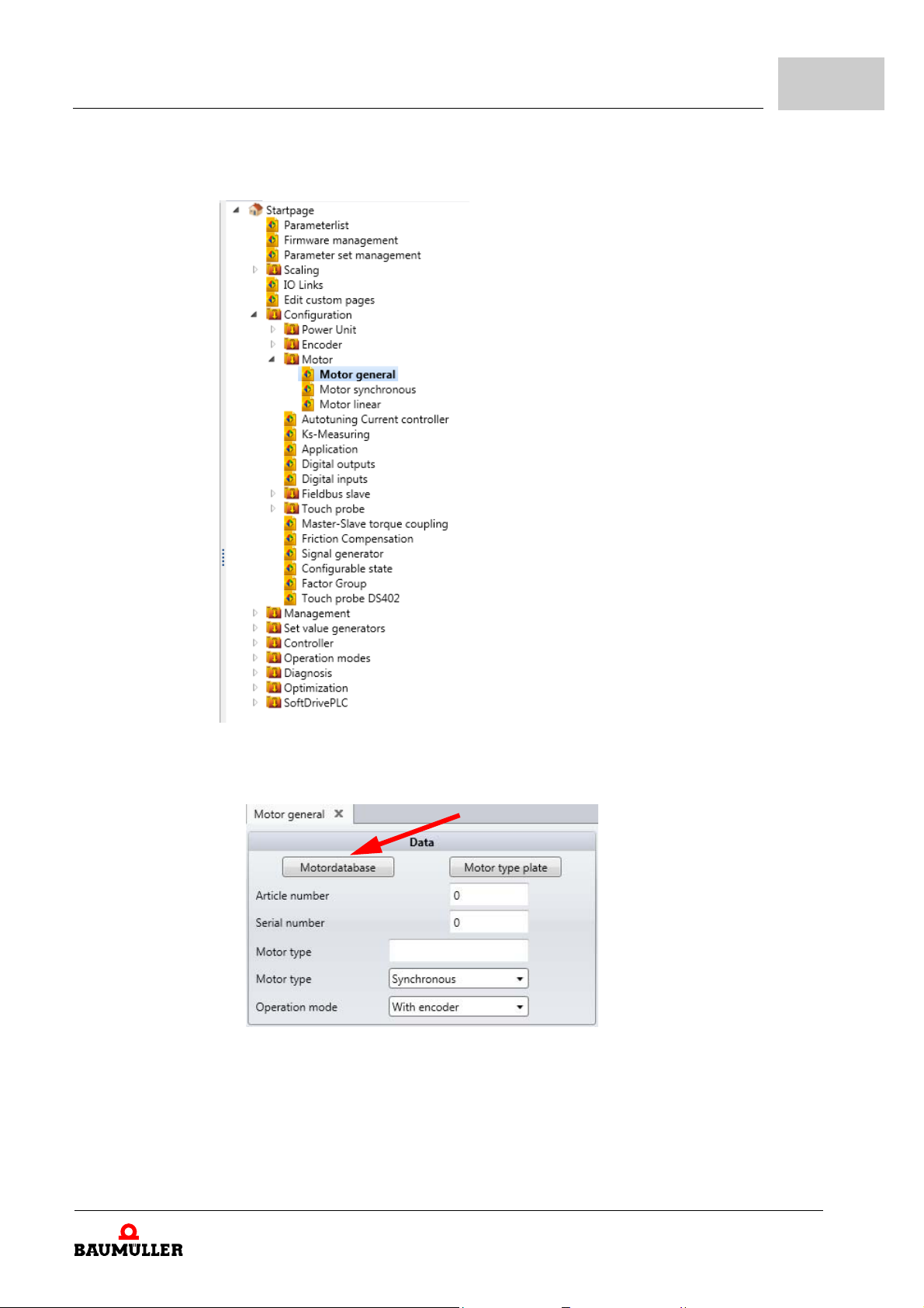
15 Change back to the navigation and click on "Motor general".
2
Using the motor
database
Figure 16: ProDrive: Navigation Motor general
16 Click on the "Motor database" button in the icon bar in the Motor window.
Figure 17: ProDrive: Motor database
17 The following window appears.
Parameter manual b maXX BM3000
Document no.: 5.12001.07
33
of 820

2.7
Performing the commissioning
Figure 18: ProDrive: Selecting the motor
18 Select the synchron motor "DS 56-S" with the following parameter in this window:
m the nominal voltage for the motor DC link: "540 V"
m the nominal speed: "6000 rpm"
m the maximum speed is automatically taken from the value for the nominal speed
NOTE
The values for nominal speed an d maximum speed are the same fo r synchronous
motors and are thus adopted for the maximum speed when selecting the nominal
speed.
With asynchronous motors, the two values must be selected separately. Software for
asynchronous motors: in preparatio n.
19 Click on the OK button.
At this point all the data will be transferred from the motor database to the corresponding
parameters and display fields.
20 Check all the values for the motor using the motor data sheets (This is only for check-
ing purposes if you are using the Baumüller motor database. If you are emp loying motors from third-party manufacturers, you must do this in any case).
34
of 820
NOTE
If you are using motors from third-party manufacturers, you can also include their
data in the motor database.
Parameter manual b maXX BM3000
Document no.: 5.12001.07 Baumüller Nürnberg GmbH
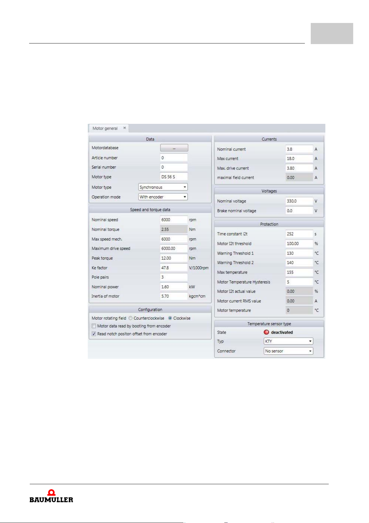
Commissioning BM25xx
2
Altering motor
data
Checking motor
data
When using the Baumüller motor database, you will not find any discrepancies between
the motor data sheet and the data taken automatically from the database.
21 Click on "Motor" in the navigation.
22 You will find all the important motor data or parameters displayed in the Motor window
and the Synchronous Motor sub-window.
Check all data.
Figure 19: ProDrive: Motor general
Parameter manual b maXX BM3000
Document no.: 5.12001.07
35
of 820

2.7
Performing the commissioning
Using the parameter list
Figure 20: ProDrive: Motor synchronous
If you are not using the Baumüller motor database, you can also enter all the motor parameters using the "Parameter list".
23 Click on the "Parameter list" in the navigation.
24 In the parameter list, click on "Motor Id".
36
of 820
Figure 21: ProDrive: Parameterlist - Motor Id
Parameter manual b maXX BM3000
Document no.: 5.12001.07 Baumüller Nürnberg GmbH

Commissioning BM25xx
The following motor parameters must be specified:
m Maximum speed, mech.(Z107.26– Maximum speed, mechanical)
m Number of pole pairs (Z107.19– Pole pairs)
m Phase sequence (Z107.38– Motor flags, Bit 0 = 0: counter-clockwise, Bit 0 = 1: clock-
wise)
Now save the entered data.
25 Click on "Parameter set management" in the navigation
2
Figure 22: ProDrive Navigation Dataset management
26 Click on the "Save all" button in the Dataset management.
Figure 23: ProDrive: Dataset management
Parameter manual b maXX BM3000
Document no.: 5.12001.07
37
of 820

2.7
Performing the commissioning
27 Wait until "Successful" is displayed under "Data Set Status"
28 At this point the data set is saved in Flash memory.
29 Disconnect the device from the main power and control voltage supplies.
30 Reconnect the power supplies to the b maXX®
(main power supply + control voltage).
By switching off and on again, you can check whether the settings you have made will
result in warnings or errors.
No errors may be present.
Autotuning of the
current controller
Now perform the autotuning of the current controller.
31 Go to the navigation and click on "Configuration", then click on "Autotuning Current
controller".
38
of 820
Figure 24: ProDrive: Navigation Autotuning Current controller
32 Activate pulse enable
33 Click on „Start“
34 Wait until „Self-optimization completed“ appears in field „Status“.
Parameter manual b maXX BM3000
Document no.: 5.12001.07 Baumüller Nürnberg GmbH

Commissioning BM25xx
2
Figure 25: ProDrive: Autotuning Current controller
Parameter manual b maXX BM3000
Document no.: 5.12001.07
39
of 820

2.7
Performing the commissioning
Searching for the
notch position
Searching for the notch position is not required at a newly delivered device. It was carried
out already.
Please check whether the measured value corresponds to the expected value
(With Baumüller motors: resolver: 330° + 5°, sine-cosine: 240° ± 5°).
If the values do not correspond to the expected values, please proceed as follows:
35 Go to the navigation and click on "Operating modes", then click on "Find notch posi-
tion".
Figure 26: ProDrive Navigation - Find notch position
36 Click on the "Drive Manager" icon.
40
of 820
Parameter manual b maXX BM3000
Document no.: 5.12001.07 Baumüller Nürnberg GmbH

Commissioning BM25xx
The "Drive Manager" window will also appear
2
Figure 27: ProDrive: Find notch position, Drive manager
37 For the method, select "fix current angle and rotating shaft".
38 Select "Find notch position" in the Drive Manager-Axis 1 window.
Parameter manual b maXX BM3000
Document no.: 5.12001.07
41
of 820

2.7
Performing the commissioning
WARNING!
Risk of injury due to moving components!
Rotating and/or linearly moving components can cause serious injuries.
If the motor is not rotating freely, the motor and parts connected to it may be damaged/destroyed.
Therefore:
m Make sure that the motor can rotate freely during commiss ion in g.
m Do not interfere with moving components during operation.
m Do not open covers during operation.
m The residual mechanical energy depends on the application. Driven components
will continue to rotate/move for a certain time, even after the energy supply has
been switched off. Provide appropriate safety devices.
39 Switch the pulse enabling to the active state.
40 Click on "Start".
41 Wait until "Successful" appears in the Status field.
42 Next click on "Stop/Off".
43 Check that the measured value corresponds to the value expected
(With Baumüller motors: resolver: 330° + 5°, sine-cosine: 240° ± 5°).
44 Switch the pulse enabling to the inactive state.
This completes all the parameter setting work for the specimen commissioning. You can
now satisfy yourself that the device is functioning correctly by having the motor rotate
briefly.
Initial rotation of
the motor
45 Go back to the navigation.
46 Click on: "Set value generators".
47 Click on: "Ramp function generator".
Figure 28: ProDrive: Navigation Ramp function generator
42
of 820
Parameter manual b maXX BM3000
Document no.: 5.12001.07 Baumüller Nürnberg GmbH

Commissioning BM25xx
2
Figure 29: ProDrive: Ramp function generator
48 Enter values in the following input fields:
m (Ramp function generator) Input
h Enter the value "10". Confirm with Enter.
49 Open the Drive manager dialog
Figure 30: ProDrive: Drive manager
Parameter manual b maXX BM3000
Document no.: 5.12001.07
43
of 820

2.7
Performing the commissioning
50 Select the "Speed control mode“ from the scroll list in the Drive Manager dialog.
51 Switch the pulse enabling to the active state.
52 Click on the "Start" button in the Drive Manager dialog.
53 The motor should now rotate at 10% of the maximum speed.
54 Click on the "Stop/Off" button in the Drive manager dialog.
55 The motor will then stop.
56 Switch the pulse enabling off.
Saving the data
set
This data set should now be saved.
57 Click on the "Dataset management" icon in the icon bar.
58 Click on the "Save All" button in the Dataset management.
Figure 31: ProDrive: Dataset management
59 Wait until "OK" is displayed under "Data Set State"
At this point the data set is saved in Flash memory.
Switching off the
drive
44
of 820
To conclude the commissioning, the drive is switched off.
60 Disconnect the device from the main power supply and the control voltage using the
appropriate switching elements.
This successfully completes the commissioning for Axis 1.
Parameter manual b maXX BM3000
Document no.: 5.12001.07 Baumüller Nürnberg GmbH

3COMMISSIONING BM3XXX
This chapter describes a specimen commissioning of a b maXX® axis unit BM3xxx in
conjunction with a Baumüller DS56-S motor.
Perform the commissioning to satisfy yourself that the supplied device is functioning properly.
This commissioning does not constitute a complete set-up of the device for your application.
Before the commissioning, make sure that the technical requirements are met:
1 All points, including the installation, in the b maXX® 3000 Operating Manual
(5.11018) have been followed.
2 Check of the requirements for the electrical supply.
3 Check of the requirements for the electrical cables and provision of appropriate ca-
bles.
4 Check of the characteristics of the connections and manufacture of the appropriate
cables.
Parameter manual b maXX BM3000
Document no.: 5.12001.07
45
of 820

3.1
Safety information
3.1 Safety information
NOTE!
The installation and initial commissioning are carried out exclusively by the manufacturer's employees or by qualified personn el.
Qualified personnel are persons who, due to their training, experience, instruction
and knowledge of the relevant standards and specifications, accident preventio n reg
ulations and operating condition s of the person responsible for the safety of the installation have been authorized to carr y out the activities required in each case and
in so doing are able to recognize and avoid potential dangers. The qualifications re
quired for working on the unit are, for example:
m Training or instruction or authorization to commission, ground and characterize
power circuits and devices in accordance with safety engineering standards.
m Training or instruction in accordance with safety engineering standar ds in the care
and use of appropriate safety equipment.
-
-
WARNING!
Danger due to incorrect installation and initial commissioning!
Installation and initial commissioning require qualified personnel with adequate expe-
rience. Errors during installation can lead to life-threatening situations or result in significant material damage.
Therefore:
m Have the installation and initial commissioning carried out exclusively by the man-
ufacturer's employees or by qualified personnel.
46
of 820
Parameter manual b maXX BM3000
Document no.: 5.12001.07 Baumüller Nürnberg GmbH

Commissioning BM3xxx
3300_0009 .cdr_rev01_int
DANGER!
Danger to life from electric current!
When this electrical unit is operated, certain parts of the unit are of necessity at a ha z-
ardous voltage.
Therefore:
m Pay attention to the areas on the device that could be dangerous during the elec-
trical installation.
3
Figure 32: Danger areas during electrical installation
3.2 Voltage test
DANGER!
Risk of fatal injury from electrical current!
During the routine test of these devices, a voltage test is performed by Baumüller
Nürnberg GmbH in accordance with EN
essary for the customer to do this.
Therefore:
m Subsequent tests of the devices using high voltages may only be performed by
Baumüller Nürnberg GmbH.
m Disconnect the converter from the system during high-voltage testin g!
3.3 Requirements for the electrical supply
61800-5-1, Section 5.2.3.2. It is thus unnec-
For all important data, see the Operating Manual for the b maXX 3300.
Small deviations in the electrical supply from the requirements can result in malfunctions
of the device. If the supply deviates greatly from the requirements, the device could be
destroyed.
Parameter manual b maXX BM3000
Document no.: 5.12001.07
47
of 820

3.4
Preparations
The device may only be operated in environments of the second type (i ndustr ial enviro nment).
The destruction of the device can cause personal injury.
3.4 Preparations
DANGER!
Danger to life from electric current!
If the requirements for the electrical supply are not complied with, the d evice may be
damaged/destroyed and consequently present a significant danger to persons.
Therefore:
m Before installation, make sure that the requirements for the electrical supply are
met.
Specimen installation of a BM3xxx axis unit with a Baumüller Motor DS 56-S motor
(SRS50 encoder, sine-cosine with Hiperface
The prerequisite for the commissioning is that assembly and installation have been carried out correctly.
1 Make sure that the assembly is carried out correctly and, in particular, that all safety
regulations have been observed (see Assembly in the Operating Manual for the
b
maXX® 3000 basic unit).
NOTE
Pictures for the next work steps can be found in the Operating Manual for the
b
maXX® 3000 basic unit and in the ZInstallation plan– on page 49.
2 Make sure that the installation is carried out correctly and, in particular, that all safety
regulations have been observed (see Installation in the Operating Manual for the
b
maXX® 3000 basic unit).
®
).
48
of 820
Parameter manual b maXX BM3000
Document no.: 5.12001.07 Baumüller Nürnberg GmbH

Commissioning BM3xxx
3
Figure 33: Installation plan
3 ProDrive must be installed on the PC/Laptop.
During commissioning you can, among other things, enter motor and encoder data in
the operating software or correct incorrect values. So that you can perform the com
missioning efficiently, it is advantageous to have all the data at hand for the commissioning. Data for Baumüller motors are available in the form of a "Motor Database"
within the operating software.
4 Make sure that all the necessary data are at hand.
Parameter manual b maXX BM3000
Document no.: 5.12001.07
-
49
of 820

3.4
Preparations
Motor data
(Identification
plate)
Motor data
(Data sheet)
These data can be found, e.g., on the identification plate for the motor that you are using
for the commissioning.
Name Value, e.g. Used for entering in the parameter list /parame-
ter
Motor type, designation DS 56-M Parameter list/Motor configuration
Z107.2– Motor type
Nominal voltage U
Nominal current I
Nominal speed n
N
N
N
330 V Parameter list/Motor configuration
Z107.8– Motor nominal voltage
4,0 A Parameter list/Motor configuration
Z107.9– Motor nominal current
3000 rpm Parameter list/Motor configuration
Z107.7– Motor nominal speed
The motor database is used in this example; the values in the table are provided only for
checking purposes.
These data can be found on the data sheet for the motor that you are using for the commissioning.
Name Value, e.g. Used for entering in the parameter list /parame-
ter
Max. current I
Number of pole pairs 3 Parameter list/Motor configuration
Max. speed n
Notch angle, if specified
1)
You can also have ProDrive determine the notch angle (see ZSearching for the notch position– on page 71).
mot,max
max.
1)
14,3 A Parameter list/Motor configuration
Z107.21– Maximum drive current
Z107.19– Pole pairs
6000 Parameter list/Motor configuration
Z107.26– Maximum speed mechanical
240° Parameter list/Motor configuration
Z127.8– Encoder Offset el.
Encoder data
(Data sheet)
These data can be found on the data sheet for the encoder that you are using for the commissioning.
Name Value, e.g. Used for entering in the parameter list /parame-
ter
Encoder type Stegmann SRS
50/60 SinCos
encoder
Number of pulses 1024 Parameter list/Encoder configuration/
With sine-cosine encoders with HIPERFACE® interface, the encoder type is read in automatically via
the HIPERFACE
Z137.1– Number of pulses
®
interface
5 Make sure that the motor meets the following conditions:
m provided with a suitable encoder, in this example: SRS50 SinCos encoder
m connected to b maXX® 3000
m ready for operation
m properly secured
m can rotate freely during commissioning
6 Make sure that switching elements for pulse enabling ar e connected to the b maXX
3000 (e.g. in a patch panel) and are functioning. Make sure that the switch is in the
rest position (inactive).
®
50
of 820
Parameter manual b maXX BM3000
Document no.: 5.12001.07 Baumüller Nürnberg GmbH
7 Make sure that all safety devices are connected on the supply and motor sides and
are ready for operation.
8 Make sure that the encoder for motor control (sine-cosine encoder) is connected to
the encoder evaluation module with the appropriate encoder cable.
9 Make sure that the PC/Laptop is connected to the controller.
3.4.1 Communication via the service cable
The service interface transmits controller parameters from a PC/laptop to the controller
via the parameterizing software ProDrive.
h Connect free USB-port of the PC/laptop with the controller
NOTE
The service cable BM5-K-USB-XXX must be used for the service interface X1, only.
Commissioning BM3xxx
3
The driver connection was installed on the PC/laptop with ProDrive, already. The settings
of the connection (baudrate etc.) are made in ProDrive. Refer to the online-help of
ProDrive.
Parameter manual b maXX BM3000
Document no.: 5.12001.07
51
of 820

3.4
3.4.2 Communication via EtherCAT
Preparations
BM3000 with EtherCAT® with the following type code is required:
BM3XXX-XXXX-XXXXX[-X]-1XXXX[-S0X]-XX[-XX][-EXX][-#XX]
For the communication via EtherCAT the following is required:
m EtherCAT Master BMC-M-ECT-02
m Controller BMC-M-PLC-02
m Power supply unit BMC-M-PSB-01
m Engineering Framework ProMaster
n Leave the base address on the EtherCAT Master un changed (192.168.1.1).
n Set the desired IP address on the BM3000 controller (here 192.168.1.2).
You will find further information about this in the b maXX BM3000, 5.11018 Operating
Manual, Art. No. 441839.
n Set a fixed IP address on the PC or use a second network card:
System Control Network Connections LAN Connection Properties
Internet Protocol (TCP/IP) Properties Assign fixed IP address
from the same address space (here, e.g. 192.168.1.254).
52
of 820
Figure 34: Setting fixed IP addresses
n Start ProMaster.
n Select b maXX controller PLC with EtherCAT Master from the catalog.
n Select b maXX 3300 Drive from the catalog.
n Open/activate the Workspace window.
Parameter manual b maXX BM3000
Document no.: 5.12001.07 Baumüller Nürnberg GmbH

Commissioning BM3xxx
n Click the Controller PLC in ProMaster.
n Click EtherCAT Master Configure Master Bus (ProEtherCAT) in the Worksp ace win-
dow.
n The window will open:
3
Figure 35: ProEtherCAT
n Click on Connect.
n Select the tab Download Update list Download
Figure 36: ProEtherCAT Download
n Click on Close.
n Select the tab Bus control click on Operational.
Parameter manual b maXX BM3000
Document no.: 5.12001.07
53
of 820

3.4
Preparations
n Start ProDrive and select "Find device".
Figure 37: ProDrive: Find device
n The PLC will appear here with 192.168.1.1 and the controller with 192.168.1.2.
n Click on OK
54
of 820
Parameter manual b maXX BM3000
Document no.: 5.12001.07 Baumüller Nürnberg GmbH

Commissioning BM3xxx
n Select the device: Button SELECT DEVICE
n Select the device type for which parameters are to be set: Button TYPE
(here: bmaXX52_TwoAxis_EtherCAT_Slave)
n Select the communication: Button TYPE (here: TCP/IP)
3
Figure 38: ProDrive: Device select with EtherCAT communication
10 Start the graphical user interface by clicking on "OK".
Parameter manual b maXX BM3000
Document no.: 5.12001.07
55
of 820
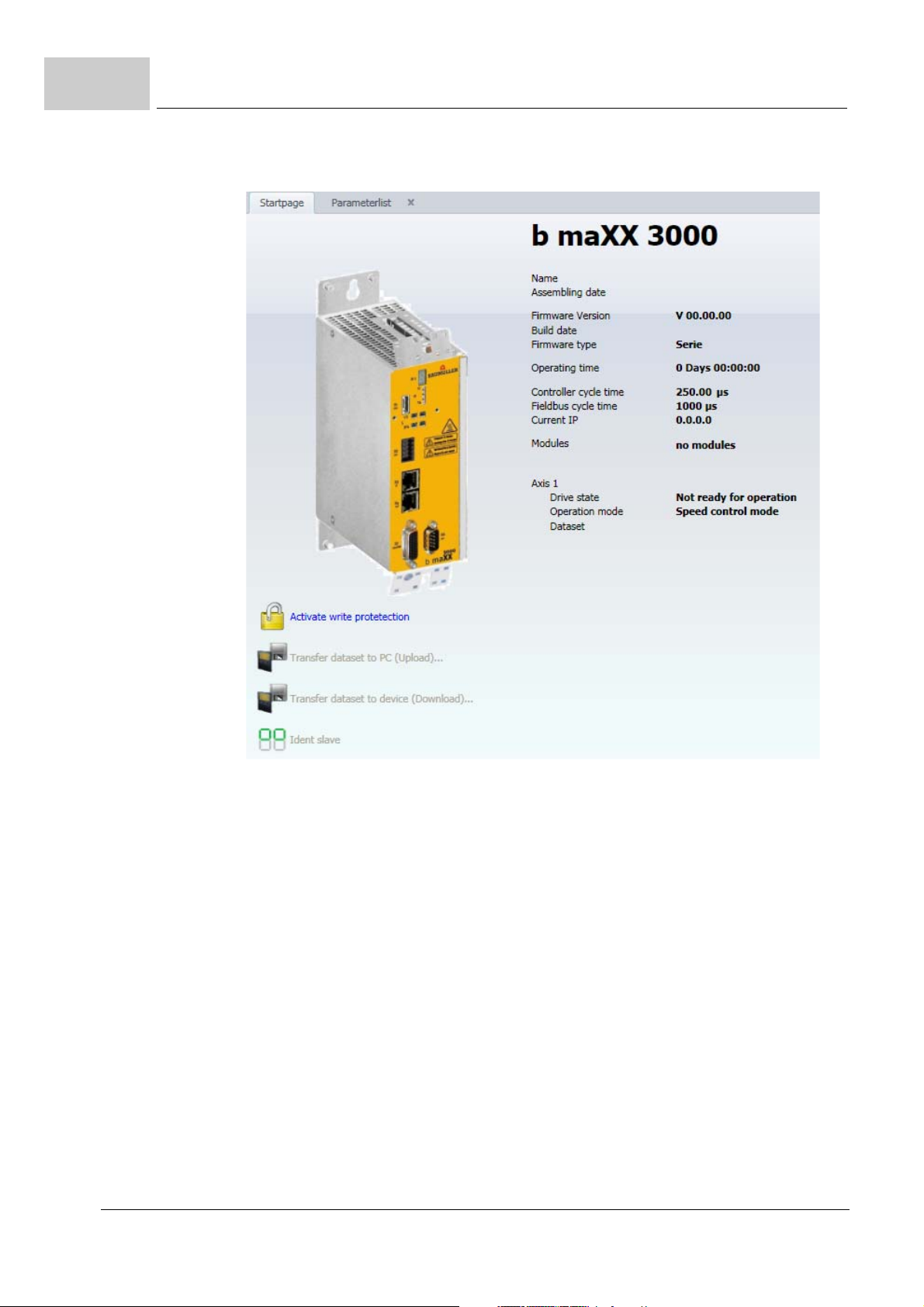
3.4
Preparations
11 Wait until the ProDrive start window appears.
Figure 39: ProDrive: Start window
12 Then press
"Connect".
13 This concludes the preparations. The remainder of the commissioning is described in
ZPerforming the commissioning– on page 58.
56
of 820
Parameter manual b maXX BM3000
Document no.: 5.12001.07 Baumüller Nürnberg GmbH

3.5 Switch-on sequence
The following overview shows the commissioning schematically. You will find the individual steps of the commissioning described in detail in ZPerforming the commissioning–
from page 58.
Commissioning BM3xxx
3
Figure 40: Switch-on sequence
Parameter manual b maXX BM3000
Document no.: 5.12001.07
57
of 820

3.6
Performing the commissioning
3.6 Performing the commissioning
Begin the commissioning after you have completed the preparations.
1 Connect the power supplies to the b maXX®
(main power supply + control voltage).
The device then starts up and indicates that it is ready for operation by lighting the
orange 'Power ON' LED H12.
m LED H12 must light up orange; this signifies Power ON and the device is ready for
operation.
m LED H12 must not light up green: when LED H12 lights up gr een , it me an s "Opera-
tion enabled"! The motor is supplied with current and can rotate! Override this immediately with the pulse enable switching element!
m LED H13; a red LED means that the current limit has been reached. Reduce the
loading on the motor. Continue with the parameter setting.
m LED H14; a red LED indicates a error condition. Rectify the error later using the
ProDrive operating program. Continue with the parameter setting.
2 Establish communication as described in ZPreparations– on page 48.
3 Start the ProDrive program (if it is not already running).
4 Then click on auf "Drive Manager" in ProDrive
Acknowledging
warnings/errors
58
of 820
Figure 41: ProDrive: Navigation Drive manager
5 "Acknowledge" any warnings/errors that may be present in the "Drive manager" win-
dow (press the "Reset errors" button several times if necessary).
NOTE
Any queued error messages may result from the as yet incomplete parameter setting.
These errors cannot be acknowledged.
Parameter manual b maXX BM3000
Document no.: 5.12001.07 Baumüller Nürnberg GmbH

Commissioning BM3xxx
.
3
Figure 42: ProDrive: Drive Manager
NOTE
Due to the numerous possible combinations of motors and encoders, it is only possible to give an example here. Enter your own motor and encoder data!
Parameter manual b maXX BM3000
Document no.: 5.12001.07
59
of 820

3.6
Performing the commissioning
6 Click on "Power unit".
Figure 43: ProDrive: Navigation for Power unit
7 In the "Maximum drive current" box, enter the current required for your application, at
most the limiting current of the motor (according to the data sheet): 2.5 A, at which
you wish to operate the motor and the power unit.
60
of 820
Parameter manual b maXX BM3000
Document no.: 5.12001.07 Baumüller Nürnberg GmbH

Commissioning BM3xxx
3
Figure 44: ProDrive: Power unit
Parameter manual b maXX BM3000
Document no.: 5.12001.07
61
of 820

3.6
Performing the commissioning
Setting encoder
parameters
The parameters for the encoder still have to be entered.
8 Go back to the navigation.
9 Click on „Scaling“
Figure 45: ProDrive: Navigation Scaling
The „Scaling“ window opens:
62
of 820
Figure 46: ProDrive: Scaling
10 Click on % at speed
Parameter manual b maXX BM3000
Document no.: 5.12001.07 Baumüller Nürnberg GmbH

11 Go back to the navigation.
12 Click on "Encoder 1".
Commissioning BM3xxx
3
Figure 47: ProDrive: Navigation Encoder
Parameter manual b maXX BM3000
Document no.: 5.12001.07
63
of 820

3.6
Performing the commissioning
The "Encoder 1 Configuration" window opens.
64
of 820
Figure 48: ProDrive: Encoder 1 configuration
13 Enter data when using a sine-cosine encoder without a HIPERFACE® interface. With
a sine-cosine encoder with a HIPERFACE
matically over the HIPERFACE® interface - do not alter the data.
m Sine-cosine without HIPERFACE® e.g. Number of Pulses = 512
m Sine-cosine without HIPERFACE® e.g. Revolutions = 1
14 Enter the overspeed limit manually in the parameter list in the diagnostic block
[FB:006]:
Parameter number 006.005 and 006.007: enter the value 115%,
Parameter number 006.006 and 006.008: enter the value -115%
Parameter manual b maXX BM3000
Document no.: 5.12001.07 Baumüller Nürnberg GmbH
®
interface, the data are transferred auto-

Commissioning BM3xxx
15 Change back to the navigation and click on "Motor general".
3
Using the motor
database
Figure 49: ProDrive: Navigation Motor general
16 Click on the "Motor database" button in the icon bar in the Motor window.
Figure 50: ProDrive: Motor database
17 The following window appears.
Parameter manual b maXX BM3000
Document no.: 5.12001.07
65
of 820
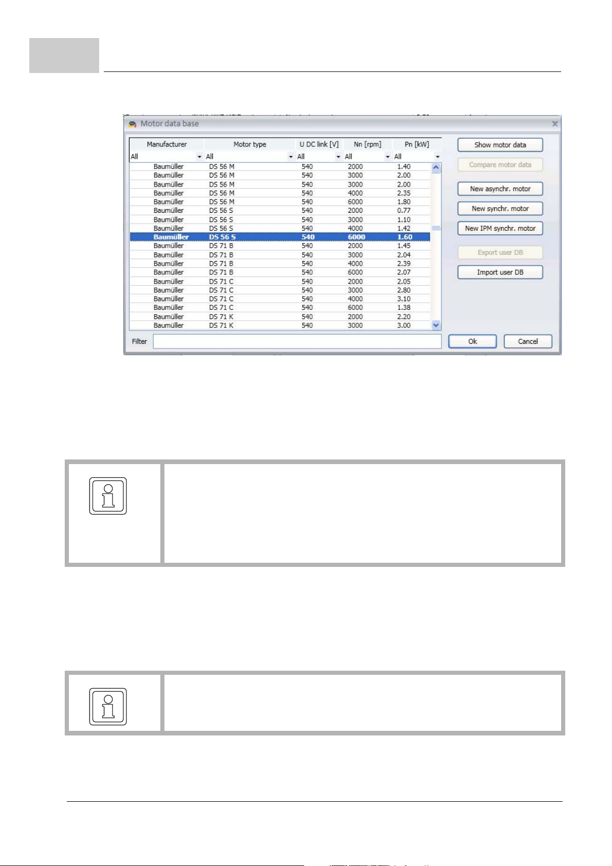
3.6
Performing the commissioning
Figure 51: ProDrive: Selecting the motor
18 Select the synchron motor "DS 56-S" with the following parameter in this window:
m the nominal voltage for the motor DC link: "540 V"
m the nominal speed: "6000 rpm"
m the maximum speed is automatically taken from the value for the nominal speed
NOTE
The values for nominal speed an d maximum speed are the same fo r synchronous
motors and are thus adopted for the maximum speed when selecting the nominal
speed.
With asynchronous motors, the two values must be selected separately. Software for
asynchronous motors: in preparatio n.
19 Click on the OK button.
At this point all the data will be transferred from the motor database to the corresponding
parameters and display fields.
20 Check all the values for the motor using the motor data sheets (This is only for check-
ing purposes if you are using the Baumüller motor database. If you are emp loying motors from third-party manufacturers, you must do this in any case).
Altering motor
data
66
of 820
NOTE
If you are using motors from third-party manufacturers, you can also include their
data in the motor database.
When using the Baumüller motor database, you will not find any discrepancies between
the motor data sheet and the data taken automatically from the database.
21 Click on "Motor" in the navigation.
Parameter manual b maXX BM3000
Document no.: 5.12001.07 Baumüller Nürnberg GmbH

Commissioning BM3xxx
3
Checking motor
data
22 You will find all the important motor data or parameters displayed in the Motor window
and the Synchronous Motor sub-window.
Check all data.
Figure 52: ProDrive: Motor general
Parameter manual b maXX BM3000
Document no.: 5.12001.07
67
of 820

3.6
Performing the commissioning
Using the parameter list
Figure 53: ProDrive: Motor synchronous
If you are not using the Baumüller motor database, you can also enter all the motor parameters using the "Parameter list".
23 Click on the "Parameter list" in the navigation.
24 In der parameter list, click on "Motor Id".
68
of 820
Figure 54: ProDrive: Parameterlist - Motor Id
The following motor parameters must be specified:
m Maximum speed, mech.(Z107.26– Maximum speed, mechanical)
m Number of pole pairs (Z107.19– Pole pairs)
Parameter manual b maXX BM3000
Document no.: 5.12001.07 Baumüller Nürnberg GmbH

Commissioning BM3xxx
m Phase sequence (Z107.38– Motor flags, Bit 0 = 0: counter-clockwise, Bit 0 = 1: clock-
wise)
Now save the entered data.
25 Click on "Dataset management" in the navigation
3
Figure 55: ProDrive Navigation Dataset management
26 Click on the "Save All" button in the Dataset management.
Figure 56: ProDrive: Dataset management
27 Wait until "Successful" is displayed under "Data Set Status"
28 At this point the data set is saved in Flash memory.
29 Disconnect the device from the main power and control voltage supplies.
30 Reconnect the power supplies to the b maXX®
(main power supply + control voltage).
Parameter manual b maXX BM3000
Document no.: 5.12001.07
69
of 820

3.6
Performing the commissioning
By switching off and on again, you can check whether the settings you have made will
result in warnings or errors.
No errors may be present.
Autotuning of the
current controller
Now perform the autotuning of the current controller.
31 Go to the navigation and click on "Configuration", then click on "Autotuning Current
controller".
70
of 820
Figure 57: ProDrive: Navigation Autotuning Current controller
32 Activate pulse enable
33 Click on „Start“
34 Wait until „Self-optimization completed“ appears in field „Status“.
Parameter manual b maXX BM3000
Document no.: 5.12001.07 Baumüller Nürnberg GmbH

Commissioning BM3xxx
3
Searching for the
notch position
Figure 58: ProDrive: Autotuning Current controller
It is now necessary to search for the notch position.
35 Go to the navigation and click on "Operating Modes", then click on "Find Notch Posi-
tion".
Parameter manual b maXX BM3000
Document no.: 5.12001.07
71
of 820

3.6
Performing the commissioning
Figure 59: ProDrive Navigation - Find notch position
36 Click on the "Drive Manager" icon.
72
of 820
Parameter manual b maXX BM3000
Document no.: 5.12001.07 Baumüller Nürnberg GmbH

Commissioning BM3xxx
The "Drive Manager" window will also appear
3
Figure 60: ProDrive: Rastlage suchen, Antriebsmanager
37 For the method, select "fix currentangle and rotating shaft".
38 Select "Find notch position" in the Drive Manager-Axis 1 window.
Parameter manual b maXX BM3000
Document no.: 5.12001.07
73
of 820

3.6
Performing the commissioning
WARNING!
Risk of injury due to moving components!
Rotating and/or linearly moving components can cause serious injuries.
If the motor is not rotating freely, the motor and parts connected to it may be damaged/destroyed.
Therefore:
m Make sure that the motor can rotate freely during commiss ion in g.
m Do not interfere with moving components during operation.
m Do not open covers during operation.
m The residual mechanical energy depends on the application. Driven components
will continue to rotate/move for a certain time, even after the energy supply has
been switched off. Provide appropriate safety devices.
39 Switch the pulse enabling to the active state.
40 Click on "Start".
41 Wait until "Successful" appears in the Status field.
42 Next click on "Stop/Off".
43 Check that the measured value corresponds to the value expected
(With Baumüller motors: resolver: 330° + 5°, sine-cosine: 240° ± 5°).
44 Switch the pulse enabling to the inactive state.
This completes all the parameter setting work for the specimen commissioning. You can
now satisfy yourself that the device is functioning correctly by having the motor rotate
briefly.
Initial rotation of
the motor
45 Go back to the navigation.
46 Click on: "Set value generators".
47 Click on: "Ramp function generator".
Figure 61: ProDrive: Navigation Ramp function generator
74
of 820
Parameter manual b maXX BM3000
Document no.: 5.12001.07 Baumüller Nürnberg GmbH

Commissioning BM3xxx
3
Figure 62: ProDrive: Ramp function generator
48 Enter values in the following input fields:
m (Ramp function generator) Input
h Enter the value "10". Confirm with Enter.
49 Open the Drive manager dialog
Figure 63: ProDrive: Drive manager
Parameter manual b maXX BM3000
Document no.: 5.12001.07
75
of 820

3.6
Performing the commissioning
50 Select the "Speed control mode“ from the scroll list in the Drive Manager dialog.
51 Switch the pulse enabling to the active state.
52 Click on the "Start" button in the Drive Manager dialog.
53 The motor should now rotate at 10% of the maximum speed.
54 Click on the "Stop/Off" button in the Drive manager dialog.
55 The motor will then stop.
56 Switch the pulse enabling off.
Saving the data
set
This data set should now be saved.
57 Click on the "Dataset management" icon in the icon bar.
58 Click on the "Save All" button in the Dataset management.
Figure 64: ProDrive: Dataset management
59 Wait until "OK" is displayed under "Data Set State"
At this point the data set is saved in Flash memory.
Switching off the
drive
76
of 820
To conclude the commissioning, the drive is switched off.
60 Disconnect the device from the main power supply and the control voltage using the
appropriate switching elements.
This successfully completes the commissioning for Axis 1.
Parameter manual b maXX BM3000
Document no.: 5.12001.07 Baumüller Nürnberg GmbH

4DESCRIPTION OF THE SOFTWARE
MODULES AND PARAMETERS
In this chapter, the parameters are described according to their use in the softwa re mod ules. The structure of this chapter corresponds to the structure of ProDri ve. Individual parameters which are used on various screens of ProDrive are described in their fun ctional
blocks and are linked.
4.1 Cycle times of the software modules
Software module Cycle time
Current controller 62,5 µs to 250 µs; depending on the preset PWM Frequency
Z130.15–; effective cycle time readable in Z47.65–
Speed controller, position controller
Two-level controller 1 ms
Operation modes of the
task RT1 *
Operation modes of the
fieldbus task *
Cam generator Adjustable in fieldbus cycle time Z131.18– and division ratio
Drive manager 1 ms
Ramp function generator Settable: RT1-cycle time (1 ms; default setting) or fieldbus
Set value generator 1 ms
Analogous inputs 125 µs, 250 µs, 500 µs or RT1-Cycle time
Analogous outputs Adjustable values: 62,5 µs, RT0-Cycle time or RT1-Cycle
Digital inputs 1 ms
62.5 µs to 1000 µs; adjustable in RT0-Cycle time Z1.8–
1 ms
Adjustable in fieldbus cycle time Z131.18– and division ratio
fieldbus task Z131.20–
fieldbus task Z131.20–
task cycle.
Effective cycle time can be read in Z110.22–
time
Parameter manual b maXX BM3000
Document no.: 5.12001.07
77
of 820

4.2
Structure of the parameter overviews
Digital outputs Remaining time
Configurable status word 1 ms
Oscilloscope function Adjustable from 62,5 µs to 100 s.
*) this mean s the cycle of the set value gene ration, the cycl e of the monitori ngs,
the cycle of the management and the cycle of the other functions of the preset
operation mode Z109.1–.
Z109.1– Operation mode Task
-12 Coupled operation Fieldbus
-7 Autotuning Remaining time (management)
-6 Spindle positioning RT1
-5 Synchronous operation with virtual master axis RT1
Synchronous operation with real master axis RT0 (set value), RT1
(Management)
-4 Position control with synchronous set of set-
points
-3 Speed control with ramp function generator RT1 (default setting) or
-2 Current control RT0
-1 Notch position search RT1
1 Target position setting RT1
2 Speed setting 1 with ramp function generator RT1 (default setting) or
5 Manual drive operation RT1
6 Reference run operation RT1
4.2 Structure of the parameter overviews
All parameter overviews are structured according to the following pattern:
Fieldbus
fieldbus
fieldbus
Number Name Type Min Max Default Value Unit Factor
1.1 System clock FLOAT 0 1000000000 0 sec 1:1 X
1.2 System ticks RT1 UDINT 0 0xFFFFFFFF 0 1:1 X
Number = Number of the parameter consisting of ID of the functional block (FB) and the
numbering within the FB
78
of 820
Parameter manual b maXX BM3000
Document no.: 5.12001.07 Baumüller Nürnberg GmbH
Read only
Storage
DS Support
Cyclic Write

Description of the Software Modules and Parameters
Name = Common parameter name for ProDrive and Parameter Manual
Type = Data type
INT Integer 16 bit
DINT Integer 32 bit
UINT Unsigned Integer 16 bit
UDINT Unsigned Integer 32 bit
WORD Word 16 bit
DWORD Double Word 32 bit
FLOAT Float 32 bit
STRING String (characters)
RECORD Composite data type (Struct, Array, etc.)
Min = Range of values of the parameter, minimum value at internal standardization
Max = Range of values of the parameter, maxi mum value at internal standa rdization
Default Value = Default value at internal standardization
Unit = Unit of the parameter for display in ProDrive
Factor = Conversion factor between display ProDrive and internal standardization
X in column „Read only“ = Parameter is read-only
4
X in column „Storage“ = Parameter will be stored in Flash
X in column „DS support“ = Parameter will be stored in data sets of the
Flash
X in column „Cyclic Write“ = Parameter may be written cyclic, e.g. using
process data of the fieldbus
Example:
Number Name Type Min Max Default Value Unit Factor
110.5 Input 16 bit INT -16384 16384 0 % 4000
100%
Number Z110.5– Functional block ramp function generator, parameter 5
Name Input 16 bit Name of parameter, display ProDrive english
Type INT Integer 16 bit
Min ... Max -16384 to 16384 Range of values
hex
Read only
:
Storage
DS Support
X X X
Cyclic Write
Default Value 0 Default value 0 at internal standardization
Unit % Unit % for ProDrive
Factor 4000
The parameter is writable, cyclic writable, it will be stored namely in all data sets.
: 100% 100% in ProDrive correspond to 16384 internal
hex
Parameter manual b maXX BM3000
Document no.: 5.12001.07
79
of 820

4.3
System
4.3 System
4.3.1 System control
4.3.1.1 Parameter overview
Functional blocks: System control 1 [1]
System control 2 [2]
FbVersion [102]
FbSystem [139]
FbSysPerformance[158]
Number Name Type Min Max Default Value Unit Factor
1.1 System clock UDINT 0 0xFFFFFFFF 0 s 1:1 X
1.2 System ticks RT1 UDINT 0 0xFFFFFFFF 0 1:1 X
1.3 System ticks RT2 UDINT 0 0xFFFFFFFF 0 1:1 X
1.8 RT0-cycle time FLOAT 62.50 1000.00 250.00 µs 1:1 X
1.10 Task fieldbus cycle time UDINT 125 8000 1000 µs 1:1 X
102.1 Firmware number UDINT 0 0xFFFFFFFF 0 1:1 X
102.2 Firmware version UDINT 0 0xFFFFFFFF 0 1:1 X
102.3 Firmware type UDINT 0 5 0 1:1 X
102.4 Firmware build number UDINT 0 0xFFFFFFFF 0 1:1 X
102.5 Firmware name STRING 1:1 X
102.6 Firmware version information STRING 1:1 X
102.7 Firmware time stamp STRING 1:1 X
102.8 Bootloader0 version STRING 1:1 X
102.9 Bootloader1 version STRING 1:1 X
102.10 Fpga Id UDINT 0 0xFFFFFFFF 0 1:1 X
102.11 Bootloader flags UDINT 0 0xFFFFFFFF 0 1:1 X
102.13 Expected system Fpga Id UDINT 0 0xFFFFFFFF 0 1:1 X
102.14 FPGA version UDINT 0 0xFFFFFFFF 0 1:1 X
102.15 FPGA firmware number UDINT 0 0xFFFFFFFF 0 1:1 X
102.18 Fieldbus controller firmware
number
102.19 Fieldbus controller firmware
version
102.20 Fieldbus controller firmware
version time stamp
102.21 Fieldbus controller firmware
type
102.22 Fieldbus controller firmware
build number
102.23 Board data command UINT 0 0x1000 0 1:1
UDINT 0 0xFFFFFFFF 0 1:1 X
UDINT 0 0xFFFFFFFF 0 1:1 X
STRING 1:1 X
UDINT 0 0xFFFFFFFF 0 1:1 X
UDINT 0 0xFFFFFFFF 0 1:1 X
Read only
Storage
DS Support
Cyclic Write
80
of 820
Parameter manual b maXX BM3000
Document no.: 5.12001.07 Baumüller Nürnberg GmbH

Description of the Software Modules and Parameters
102.24 Board data status UDINT 0 0xFFFF 0 1:1 X
102.25 Hardware board identification STRING 1:1
102.26 Circuit board assembly STRING 1:1
102.28 Hardware date STRING 1:1
102.30 Controller serial number UDINT 0 0xFFFFFFFF 0 1:1
102.31 Controller article number UDINT 0 0xFFFFFFFF 0 1:1
102.32 Device serial number UDINT 0 0xFFFFFFFF 0 1:1
102.33 Device article number UDINT 0 0xFFFFFFFF 0 1:1
102.35 Device type Code STRING 1:1
139.1 Password UINT 0 0xFFFF 0 1:1
139.2 Baudrate UDINT 9600 921600 38400 1:1
139.25 Switch-on time UDINT 0 0xFFFFFFFF 0 s 1:1 X
139.26 Shutdown delay UDINT 0 0xFFFFFFFF 0 ms 1:1 X X
158.1 Real time load FLOAT 0 1 0 % 1:1 X
158.2 Real time load average FLOAT 0 1 0 % 1:1 X
158.3 Max real time load FLOAT 0 1 0 % 1:1 X
158.4 Interrupt load FLOAT 0 1 0 % 1:1 X
158.5 Interrupt load average FLOAT 0 1 0 % 1:1 X
158.6 Interrupt load max FLOAT 0 1 0 % 1:1 X
4
4.3.1.2 Description of the Parameters
1.1 System clock
Operation time of the controller in seconds. System clock continues to count after voltage
(24
V) was turned on and off.
1.2 System ticks RT1
Display of the value of a counter which is incremented in TASK_RT1.
1.3 System ticks RT2
Display of the value of a counter which is incremented in TASK_RT2 by the ratio
TASK_RT2/TASK_RT1, so that System Ticks RT2 and System Ticks RT1 have approx
imately the same value.
-
Parameter manual b maXX BM3000
Document no.: 5.12001.07
81
of 820

4.3
System
1.8 RT0-cycle time
The parameter for the cycle time for the RT0 time slice (for position and speed controllers
and motor control) can be set here.
The value must be between 62.5 µs and 1 ms; the standard value is 250 µs.
The RT0-cycle time can be changed only when the drive is inhibited.
The RT0-cycle time must not fall below the preset current controller cycle time
Z47.65–. This is monitored and as the case may be the error 501 will be trigg ered wh ich
inhibits enabling of the drive.
1.10 Task fieldbus cycle time
The parameter displays the cycle time for the task fieldbus.
The task fieldbus cycle time must not fall below the RT0-Cycle time. In this case the task
fieldbus cycle time is limited to the RT0-Cycle time, the error 505 will be triggered and thus
the enabling of the drive will be inhibited.
102.1 Firmware number
Internal Baumüller firmware number
102.2 Firmware version
Display of the firmware version with accordingly 2 digits for main version (incompatible
version), sub-version (compatible version) and bugfix version.
102.3 Firmware type
Classification of the Firmware
Value Meaning
0 Production
1 Beta versio
2 Prototype
82
of 820
3 Nightly Build
4 Developer Build
5 Customers version
Parameter manual b maXX BM3000
Document no.: 5.12001.07 Baumüller Nürnberg GmbH

Description of the Software Modules and Parameters
102.4 Firmware build number
Internal build number.
102.5 Firmware name
Firmware term
102.6 Firmware version information
Summarized text information of the firmware version.
102.7 Firmware time stamp
4
Time stamp for the firmware generation.
102.8 Bootloader0 version
Version of Bootloader 0.
102.9 Bootloader1 version
Version of Bootloader 1.
102.10 Fpga version
Version of the FPGA.
Parameter manual b maXX BM3000
Document no.: 5.12001.07
83
of 820

4.3
System
102.11 Bootloader flags
Flags from the Bootloader / Bootfile Management:
Bit # Meaning
0 Current BL1 was faulty, fallback used
1 Current firmware was faulty, fallback used
2 Current FPGA was faulty, fallback used
3 Current communication firmware was faulty, fallback used
4 New BL1 file has been saved in Flash
5 New firmware file has been saved in Flash
6 New FPGA file has been saved in Flash
7 New communication firmware file has been saved in Flash
8 Fallback of the communication firmware was faulty, communication firm-
ware has not been downloaded
9 Error at download communication firmware (timeout), communication
firmware has not been downloaded
102.13 Expected system Fpga version
Expected version of the system FPGA.
102.14 FPGA version
Display of the FPGA version in the format Major[2] . Minor[2] . Fix[2]
102.15 FPGA firmware number
Baumüller internal FPGA Firmware number
102.18 Fieldbus controller firmware number
Baumüller internal fieldbus firmware number
84
of 820
Parameter manual b maXX BM3000
Document no.: 5.12001.07 Baumüller Nürnberg GmbH

Description of the Software Modules and Parameters
102.19 Fieldbus controller firmware version
Display of the Fieldbus controller firmware version in the format:
Major[2] . Minor[2] . Fix[2]
102.20 Fieldbus controller firmware version time stamp
102.21 Fieldbus controller firmware type
Firmware type: 0: Production
1: Beta
2: Prototype
4
102.22 Fieldbus controller firmware build number
Number for counting beta states, prototypes or even nightly builds.
102.23 Board data command
Value/
Command
0 No command or STOP command
1 Write current data set from the parameters to the serial EEPROM
2 Read data set from the serial EEPROM
3 Initialize serial EEPROM
Command 3 is provided with a key.
Meaning
Parameter manual b maXX BM3000
Document no.: 5.12001.07
85
of 820

4.3
System
102.24 Board data status
Status code:
Value Meaning
0 No error
1 Busy – command being executed
3 Done – command has completed without errors
All other values are error codes
102.25 Hardware board identification
The HW board identifier has the following format: 33.YY.NN.BB.AA.D1 where:
YY: Year of development
NN: Sequential number
BB: Assembly variant
AA: Revision number
D1: Technical status
Format of HW board identifier: 16-byte string
e.g. "33.0707B", i.e. format: 33.JJ.NN.AA
102.26 Circuit board assembly
Format: 16-byte string e.g. "01: Safe"
102.28 Hardware date
Format: 16-byte string e.g.: "01.04.2009"
102.30 Controller serial number
86
of 820
Serial number of the controller-PCB as a 32 bit numerical value.
Parameter manual b maXX BM3000
Document no.: 5.12001.07 Baumüller Nürnberg GmbH

Description of the Software Modules and Parameters
102.31 Controller article number
Article number of the controller-PCB as a 32 bit numerical value.
102.32 Device serial number
Serial number of the device as a 32 bit numerical value.
102.33 Device article number
Article number of the device as a 32 bit numerical value.
102.35 Device type code
4
Complete BM device type code including safety level of the form:
BM3XXX-XXXX-XXXXX[-X]-XXXXX[-S0X]-XX[-XX][-EXX][-#XX]
139.1 Password
Password for protecting access to system parameters. The value disp layed co rrespond s
to the password level.
NOTE!
The controller has several possible interfaces for accessing parameters (serial interface as well as up to three EOE channels).
The handling of the password-protected levels is not interface-oriented. If an interface channel switches to a password level, the corresponding access permission
also applies to all the other channels.
139.2 Baudrate
Baud rate for serial communication
Valid baud rates: 9600, 19200, 38400, 57600, 115200, 230400, 460800, 921600 Baud
Each time the controller is switched on, the baud rate is set to 38400.
Parameter manual b maXX BM3000
Document no.: 5.12001.07
of 820
87

4.3
System
139.25 Switch-on time
The value of the system clock parameter Z1.1– is saved with this parameter after the system was started.
139.26 Shutdown delay
Setting of the shutdown delay of the controller system. A reset is carried out at the end of
this time.
158.1 Real time load
Real computing time load by the real time tasks.
158.2 Real time load average
Average value of the computing time load by the real time tasks. The parameter is refreshed every second and shows the mean computing time load since the last update.
158.3 Max real time load
Maximum value of the computing time load by the real time tasks. The parameter can be
reset by writing a value.
158.4 Interrupt load
Computing time load by the interrupt routine.
158.5 Interrupt load average
Average value of the computing time load by the interrupt routine. The parameter is refreshed every second and shows the mean computing time load since the last update.
88
of 820
Parameter manual b maXX BM3000
Document no.: 5.12001.07 Baumüller Nürnberg GmbH

Description of the Software Modules and Parameters
158.6 Interrupt load max
Maximum value of the computing time load by the interrupt routine. The parameter can
be reset by writing a value.
4
Parameter manual b maXX BM3000
Document no.: 5.12001.07
89
of 820

4.3
4.3.2 Display
4.3.2.1 Parameter overview
System
Functional block: FbDisplay [135]
Number Name Type Min Max Default Value Unit Factor
135.1 Mode error display UDINT 0 0xFFFFFFFF 0x1010000 1:1 X
4.3.2.2 Description of the Parameters
135.1 Mode Error Display
Bit Value Meaning
15 ... 0 Reserved
23 ... 16 0 Only errors (with a response set in the parameters) are displayed:
the error-LED H14 (axis
If only warnings or errors without a response set in the parameters
are triggered, the error-LED flashes
1 All errors and warning s ar e disp la ye d; the er ro r- LED is on perma-
nently in case of error or warning.
1) or H24 (axis 2) is on in case of error.
Read only
Storage
DS Support
Cyclic Write
90
of 820
24 Activation of LED Power On (H12 (axis 1) or H22 (axis 2), if power
on
0 LED is on permanently
1 LED flashes (life signs)
31 ... 25 Reserved
Parameter manual b maXX BM3000
Document no.: 5.12001.07 Baumüller Nürnberg GmbH

Description of the Software Modules and Parameters
4.4 Configuration
4.4.1 Power unit
All the power unit related data are divided into two groups. The first group includes the
so-named power unit data which is shown in paramete r group 129 and cannot be written
to.
The power unit has a non-volatile memory which holds the power unit data. When the
controller is initialized, these data are read out and transf erred to the correspo nding pa
rameters in group 129.
The second group, parameter group 130, contains all the other power unit working data.
These parameters represent either constantly changing physical quantities or certain set
tings which generally can be altered.
Detection of a mains failure
The detection of mains failure at external supply is possibly not fast enough for specific
applications. Therefore a mains failure detection is optionally possible via the DC link volt
age (see Z130.35–).
4
-
-
-
Behavior at mains failure
The drive can be configured that operation is possible at a mains failure for a set time
(
Z130.25–). Different kinds of behavior can be set (see Z130.10–):
– Disable only motor operation ( generator ope ration is enabled, field cur rent is further
supplied). This behavior is only possible at external supply.
– Normal operation (motor an d generator o peration): Normally this optio n makes only
sense at a DC link combination if another axis feeds back power to the DC link. This
behavior is only possible at external supply.
– Disabling and automatic restart: The pulses are inhibited in case of detected mains
failure. The drive changes to "Switch-on inhibit (1)" state and coasts down. If the time
of the mains failure is shorter than the set Mains failure delay (Z130.25–), the drive
restarts automatically. The drive changes automatically in the "Operation enabled"
state again.
Parameter manual b maXX BM3000
Document no.: 5.12001.07
91
of 820

4.4
Configuration
4.4.1.1 ProDrive Power Unit
Figure 65: ProDrive Power unit
4.4.1.2 Parameter overview
Functional blocks: FbPsChars [129]
FbPower_Section [130]
FbPuTempModell [175]
For Parameter 6.27 seeZDiagnosis– from page 690
For Parameters 19.6 and 107.9 see ZMotor– from page 111
For Parameters 175.1, 175.2 and 175.15 see ZDiagnosis– from page 690
Number Name Type Min Max Default Value Unit Factor
129.3 Hardware id STRING 1:1
129.4 Hardware name STRING 1:1
129.5 Current scaling gain FLOAT 0 10000 1.1862 1:1
129.6 DC scaling gain FLOAT 0 10000 1.03885 1:1
129.7 Main voltage scaling gain FLOAT 0 10000 0 1:1
129.8 Current converter configuration
129.9 IGBT dead time FLOAT 2.0 10.0 4.0 µs 1:1
UDINT 0 0xFFFFFFFF 0 1:1
Read only
Storage
DS Support
Cyclic Write
92
of 820
Parameter manual b maXX BM3000
Document no.: 5.12001.07 Baumüller Nürnberg GmbH

Description of the Software Modules and Parameters
129.10 Min pulse suppression FLOAT 0 10 2 µs 1:1
129.11 Current sampling time offset UINT 0 0xFFFF 250 1:1
129.12 Nominal current 2 kHz FLOAT 0 1000.0 4.0 A 1:1
129.13 Nominal current 4 kHz FLOAT 0 1000.0 3 A 1:1
129.14 Nominal current 8 kHz FLOAT 0 1000.0 2.1 A 1:1
129.15 Nominal current 16 kHz FLOAT 0 1000.0 1.5 A 1:1
129.16 Peak current 2 kHz FLOAT 0 1000.0 10.0 A 1:1
129.17 Peak current 4 kHz FLOAT 9 1000.0 9.0 A 1:1
129.18 Peak current 8 kHz FLOAT 0 1000.0 6.3 A 1:1
129.19 Peak current 16 kHz FLOAT 0 1000.0 4.0 A 1:1
129.20 Overcurrent threshold FLOAT 0 2000.0 16.6 A 1:1
129.21 Max. DC-link voltage FLOAT 10 1000.0 835.0 V 1:1
129.22 Max peak current time UINT 0 0xFFFF 10,00 s 100:1
129.24 Max phase error delay time UINT 0 0xFFFF 0 ms 1:1
129.25 Current phase error FLOAT 0 1000.0 0 A 1:1
129.26 Max heat sink temperature UINT 0 0xFFFF 85 Grad C1:1
129.27 Max interior temperature UINT 0 0xFFFF 65 Grad C1:1
4
129.41 Max. ground current FLOAT 0.16 33.0 3.0 A 1:1
129.42 Min. DC link voltage FLOAT 10 1000.0 10.0 V 1:1
129.49 Amp article number UDINT 0 0xFFFFFFFF 0 1:1
129.50 Chopper resistance FLOAT 0 0xFFFFFFFF 100 Ohm 1:1
129.51 Chopper peak power FLOAT 0 0xFFFFFFFF 1200 W 1:1
129.52 Chopper PT1 model gain FLOAT 0 0xFFFFFFFF 1.4 1:1
129.53 Chopper PT1 model time
constant
129.55 Chopper maximum temperature
129.85 Charging blocking time UINT 0 0xFFFF 10 s 1:1
129.86 Peak current 2 kHz TM FLOAT 0 1000.00 10.00 A 1:1
129.87 Peak current 4 kHz TM FLOAT 0 1000.00 10.00 A 1:1
129.88 Peak current 8 kHz TM FLOAT 0 1000.00 10.00 A 1:1
130.1 Heat sink temperature FLOAT 0 1000 0 °C 1:1 X
130.2 Interior temperature FLOAT 0 1000 0 °C 1:1 X
130.3 DC link voltage FLOAT 10 1000 10 V 1:1 X
130.8 Mains voltage FLOAT 0.0e+0 1000 0.0e+0 V 1:1 X
130.9 Fan mode UINT 0x0000 0x0003 0x0001 1:1 X
130.10 Mode UINT 0x0000 0xFFFF 0x0000 1:1 X
130.12 Heatsink temperature warning threshold
130.13 Interior temperature warning
threshold
130.15 PWM frequency UINT 2 16 8 kHz 1:1 X X
130.18 I offset phase U FLOAT -2.56e+02 2.56e+02 0.0 A 1:1.414 X
130.19 I offset phase V FLOAT -2.56e+02 2.56e+02 0.0 A 1:1.414 X
130.20 I offset phase W FLOAT -2.56e+02 2.56e+02 0.0 A 1:1.414 X
130.24 Phase error delay time UINT 0 65535 0 ms 1:1 X
FLOAT 0 0xFFFFFFFF 7.5 1:1
FLOAT 0 0xFFFFFFFF 180 °C 1:1
UINT 0 0xFFFF 75 °C 1:1 X
UINT 0 0xFFFF 55 °C 1:1 X
Parameter manual b maXX BM3000
Document no.: 5.12001.07
93
of 820

4.4
130.25 Mains failure delay UINT 0 6000 0 ms 1:1 X
130.29 Chopper threshold FLOAT 400 780 780 V 1:1 X
130.34 Status STO module UINT 0 0xFFFF 0 1:1 X
130.35 Mains failure detection mode UDINT 0 0xFFFFFFFF 0 1:1 X
130.36 Relative Udc threshold for
130.37 Udc threshold for mains fail-
130.38 Udc hysteresis for mains fail-
130.39 Udc autodetect FLOAT 0 1000 0 V 1:1 X
130.41 Actual PWM fr equency UINT 2 16 8 kHz 1:1 X
175.3 Max. device control cabin
175.4 Max. device altitude UINT 0 5000 1000 m 1:1 X
175.5 Max. device mains voltage UINT 0 530 400 V 1:1 X
175.6 Max. device DC link voltage UINT 0 760 540 V 1:1 X
175.7 PU max.continuous current
175.8 PU I2t max. continuous cur-
Configuration
FLOAT 10 90 80 % 1:1 X
mains failure
FLOAT 10 1000 450 V 1:1 X
ure
FLOAT 10 500 50 V 1:1 X
ure
UINT 0 55 40 Grad C1:1 X
temperature
FLOAT 0 1000 4 A 1:1 X
actual value
FLOAT 0 1000 4 A 1:1 X
rent actual value
4.4.1.3 Description of the Parameters
129.3 Hardware Id
The hardware identifier has the format:
33.YYNN.[S]BB.A.01 Example: 33.1110.S01.C.01
Abbreviation Meaning
YY Year Example: 2011
NN Sequential number Example: 10
S STO module available
BB Assembly variant Example: 01
A Revision number Example: C
01 Technical status Example: 01
94
of 820
Parameter manual b maXX BM3000
Document no.: 5.12001.07 Baumüller Nürnberg GmbH

Description of the Software Modules and Parameters
129.4 Hardware name
Abbreviation Meaning
BM3201 BG0, without STO module
BM3211 BG1, without STO module
BM3301 BG0, with STO module
BM3311 BG1, with STO module
129.5 Current scaling gain
Standardization factor for current measurement, depends on the power unit.
4
129.6 DC scaling gain
Standardization factor for the DC link voltage, depends on the power unit.
129.7 Main voltage scaling gain
Standardization factor for the supply voltages, depends on the power unit.
129.8 Current converter configuration
Factory settings for the configuration
129.9 IGBT dead time
Dead time for the power unit transistors.
129.10 Min. pulse suppression
Minimum pulse suppression is used to prevent extremely short duty cycles for pulse width
modulation, such as may occur when outputting large voltages. Instead of gener ating ex
tremely short On/Off switching pulses, the switching state of the IGBTs is extended to the
next PWM period. This will further increase the maximum possible voltage setting. PWM
voltage pulses that are shorter than the parameter value will be suppressed.
Parameter manual b maXX BM3000
Document no.: 5.12001.07
-
95
of 820

4.4
Configuration
129.11 Current sampling time offset
This parameter determines the starting time of th e current measurement. For curr ent control, the fundamental of the motor currents should be measured if possib le. Th e harmo nics, which result from, among other things, the switching edges of the PWM, can distort
the measurement. The parameter can be used to take account of time-r elated influences
such as, e.g., the time constant of the analog current filter.
129.12 Nominal current 2 kHz
129.13 Nominal current 4 kHz
129.14 Nominal current 8 kHz
129.15 Nominal current 16 kHz
Nominal current of converter at the corresponding PWM switching frequency Z130.15–.
The value in this parameter applies to the required op erating conditions. See chapter
"Technical data" of the device's operating manual.
The instantaneous nominal current of the power unit dependent of the PWM frequency
entry
Z130.15– is displayed in parameter Z6.25–.
If operating conditions are changed and after current derating, the continuous current is
displayed in parameter
via temperature model. See "Status PU temperature model" Z175.2–.
Z175.7– provided that the PU-overload monitoring is executed
96
of 820
Parameter manual b maXX BM3000
Document no.: 5.12001.07 Baumüller Nürnberg GmbH

Description of the Software Modules and Parameters
129.16 Peak current 2 kHz
129.17 Peak current 4 kHz
129.18 Peak current 8 kHz
129.19 Peak current 16 kHz
The maximum accepted current of the power unit at the corresponding PWM switching
frequency
From firmware version 01.10 onwards the parameter is applicable only if the lxt model for
the PU overload monitoring is used (see status PU temperature model
Z130.15–.
4
Z175.2– Bit 0).
The value in this parameter applies to the required operating conditions: See chapter
"Technical data" of the device's operating manual.
The valid PU peak current dependent of the entered PWM frequency Z130.15–, is displayed in the parameter Z6.25–.
The value of the peak current (Z129.16– to Z129.19–, or parameter Z6.25–) corresponds to the maximum current by which the device may be operated at peak cu rrent processing time Z129.22– corresponding to the specifications in chapter "Technical data " of
the device's operating manual.
129.20 Overcurrent threshold
Monitoring the maximum converter current
129.21 Max DC-link voltage
Maximum DC link voltage
129.22 Max peak current time
The maximum time period, within the converter may be operated at peak current
Z129.16– to Z129.19–, or Z6.25– complying with the specifications in the chapter
"Technical data" of the device's operating manual.
If the PU overload monitoring model is operated by the temperatu re model (see status PU
temperature model
Z175.2–), this parameter is not important.
Parameter manual b maXX BM3000
Document no.: 5.12001.07
97
of 820

4.4
Configuration
129.24 Time phase error
Maximum time for which the drive can be operated at nominal cu rrent with a phase failure.
See also
Z130.24–.
129.25 Current phase error
If Bit 2 of the Supply Mode parameter (Z130.10–) is not set:
Maximum current at which the drive can be operated with a phase failure.
129.26 Max. heat sink temperature
Switch-off threshold for heat sink temperature
129.27 Max interior temperature
Switch-off threshold for the internal temperature of the power unit
129.41 Max. ground current
Monitoring the maximum ground current
129.42 Min. DC link voltage
Monitoring the minimum DC-Link Voltage
129.49 Amp article number
Article number of the power unit, not of the comple te unit.
98
of 820
Parameter manual b maXX BM3000
Document no.: 5.12001.07 Baumüller Nürnberg GmbH

Description of the Software Modules and Parameters
129.85 Peak current 2 kHz TM
129.86 Peak current 4 kHz TM
129.87 Peak current 8 kHz TM
129.88 Peak current 16 kHz TM
From controller firmware version V01.10 and up:
Maximum admitted current of the power unit at the accordant PWM freque ncy Z130.15–
The parameter is valid only if the temperature model for the PU overload monitoring is
used (see PU temperature model state
The value in this parameter is valid for the required operatin g require ments. See chapte r
"Technical data" in the Instruction Handbook.
The currently valid power unit peak current dependent of the entered PWM frequency
Z130.15–, is shown in parameter Z6.25–.
4
Z175.2– Bit 0)
There is no connection between the peak curren t (>129.85< to >129.88<) and the peak
current time
chapter "Technical data" of the Instruction Handbook of the device.
Z129.22–. The maximum permitted time for the peak current is specified in
130.1 Heat sink temperature
Power Unit Heat Sink Temperature
130.2 Interior temperature
Internal temperature of the device
130.3 DC link voltage
Actual value of the DC link voltage
Parameter manual b maXX BM3000
Document no.: 5.12001.07
99
of 820

4.4
Configuration
130.9 Fan mode
Bit 1...0 Meaning
00 Fan control dependent on heat sink and ambient temperature
01 Fan control dependent on the presence of main supply voltage
10 Fan is always switched off
11 Fan is always switched on
130.10 Mode
Settings for the mains rectifier unit.
The parameter is changeable only in locked status.
Bit no. Meaning
0 0: Supply from the mains via X202
1: Supply via X205
1 Behavior at mains failure:
0: The motorized operation is inhibited at mains failure
1: Motorized operation is possible if there is a mains failure
This setting is only permitted at external supply. A motorized operation is
not possible at internal supply.
2 0: Limitation of the motor current to Z129.25– Current phase error; no
shutdown
1: Limitation of the motor current to Z107.9– Nominal current, shutdown
of the drive after the duration in Z130.24– Phase error delay time
3 Reserved
4 0: Three-phase supply to X202
1: Single-phase supply to X202
If this bit is set, the message 1047 „Warning Phase Failure“ is sup-
pressed. Bit 2 may not be set at the same time!
5 Automatic restart after mains failure:
0: At mains failure the drive remains enabled for the time set in Z130.25–
Mains failure delay. According to the setting of bit 1 the motor operation
is disabled internallly.
1: At mains failure the pulses are inhibited at once and the drive changes
in the "Switch-on inhibit" state. If mains is available again within the set
time in Z130.25–, the drive is enabled automatically (automatic rest art).
It is essential generally: If the mains failure is longer than the set time in
Z130.25– an error message is generated.
100
of 820
15 ... 6 Reserved
Bit 1:
Parameter manual b maXX BM3000
Document no.: 5.12001.07 Baumüller Nürnberg GmbH
 Loading...