


Instruction handbook
Language English
Translation
Document No. 5.09021.17
Part No. 439683
Status 22-May-2019
E
5.09021.17
b maXX 5000
BM5000, BM5100
Mains rectifier/
Active mains rectifier
BM5300
Axis units safety
Read the Instruction handbook before starting any work!

Copyright This Instruction handbook may be copied by the owner in any quantity, but only for internal
use. This Instruction handbook may not be copied or reproduced, in whole or in part, for any
other purposes.
The use and disclosure of information contained in this Instruction handbook are not permitted.
Designations and company marks contained in this Instruction handbook could be trademarks, the use of which by third parties for their own purposes could violate the rights of the
rights holder.
Preliminary information
Warning Insofar as this document is identified as being preliminary information, the following
applies:
this version is regarded as providing advance technical information to users of the described
devices and their functions at an early enough time in order to adapt to any possible changes
or expanded functionality.
This information must be regarded as being preliminary, as it has not yet passed through
Baumüller's internal review process. In particular, this information is still subject to changes,
thus no legal liability can be derived from this preliminary information. Baumüller assumes no
liability for damages that might arise from this possibly faulty or incomplete version.
If you detect or suspect any content errors and/or major form errors in this preliminary information, we request that you notify the Baumüller support specialist responsible for you.
Please provide us, via this employee, with your insights and comments so that we can take
them into account and include them when transitioning from the preliminary information to
the final information (as reviewed by Baumüller).
The conditions stipulated in the following section under „Obligatory“ are invalid in case of preliminary information.
Obligatory This Instruction handbook are a part of the equipment/machine. This Instruction handbook
must be available to the operator at all times and must be in legible condition. If the equip
ment/machine is sold or moved another location, these Instruction handbook must be passed
on by the owner together with the equipment/machine.
After any sale of the equipment/machine, this original and all copies must be handed over to
the buyer. After disposal or any other end use, this original and all copies must be destroyed.
When the present Instruction handbook are handed over, corresponding sets of instruction
handbooks of a previous version are automatically invalidated.
Please note that the specifications/data/information are current values according to the
printing date. These statements are not legally binding with regard to measurements,
computation or calculations.
Baumüller Nürnberg GmbH reserves the right, in developing its products further, to change
the technical specifications and handling of it products concerned without prior notice.
No liability can be accepted concerning the correctness of these Instruction handbook unless
otherwise specified in the General Conditions of Sale and Delivery.
-
Baumüller Nürnberg GmbH
Ostendstr. 80 - 90
90482 Nuremberg
Germany
Tel. +49 9 11 54 32 - 0
Fax: +49 9 11 54 32 - 1 30
Email : mail@baumueller.de
Internet: www.baumueller.de

Table of Contents
1 General . . . . . . . . . . . . . . . . . . . . . . . . . . . . . . . . . . . . . . . . . . . . . . . . . . . . . . . . . . . . . . . . . . 9
1.1 Information on the instruction handbook . . . . . . . . . . . . . . . . . . . . . . . . . . . . . . . . . . . . 9
1.2 Key to symbols . . . . . . . . . . . . . . . . . . . . . . . . . . . . . . . . . . . . . . . . . . . . . . . . . . . . . . . 9
1.3 Limitation of liability . . . . . . . . . . . . . . . . . . . . . . . . . . . . . . . . . . . . . . . . . . . . . . . . . . . 10
1.4 Copyright protection. . . . . . . . . . . . . . . . . . . . . . . . . . . . . . . . . . . . . . . . . . . . . . . . . . . 11
1.5 Other applicable documents . . . . . . . . . . . . . . . . . . . . . . . . . . . . . . . . . . . . . . . . . . . . 11
1.6 Spare parts . . . . . . . . . . . . . . . . . . . . . . . . . . . . . . . . . . . . . . . . . . . . . . . . . . . . . . . . . 12
1.7 Disposal . . . . . . . . . . . . . . . . . . . . . . . . . . . . . . . . . . . . . . . . . . . . . . . . . . . . . . . . . . . . 12
1.8 Guarantee provisions. . . . . . . . . . . . . . . . . . . . . . . . . . . . . . . . . . . . . . . . . . . . . . . . . . 12
1.9 Customer service. . . . . . . . . . . . . . . . . . . . . . . . . . . . . . . . . . . . . . . . . . . . . . . . . . . . . 12
1.10 Terms used . . . . . . . . . . . . . . . . . . . . . . . . . . . . . . . . . . . . . . . . . . . . . . . . . . . . . . . . . 12
1.11 List of other applicable documents . . . . . . . . . . . . . . . . . . . . . . . . . . . . . . . . . . . . . . . 13
2 Safety . . . . . . . . . . . . . . . . . . . . . . . . . . . . . . . . . . . . . . . . . . . . . . . . . . . . . . . . . . . . . . . . . . 15
2.1 Contents of the Instruction handbook . . . . . . . . . . . . . . . . . . . . . . . . . . . . . . . . . . . . . 15
2.2 Changes and modifications to the device . . . . . . . . . . . . . . . . . . . . . . . . . . . . . . . . . . 15
2.3 Usage for the intended purpose . . . . . . . . . . . . . . . . . . . . . . . . . . . . . . . . . . . . . . . . . 15
2.4 Risk assessment according EU Directive . . . . . . . . . . . . . . . . . . . . . . . . . . . . . . . . . . 17
2.5 Responsibility of the operating company . . . . . . . . . . . . . . . . . . . . . . . . . . . . . . . . . . . 19
2.6 Protective devices . . . . . . . . . . . . . . . . . . . . . . . . . . . . . . . . . . . . . . . . . . . . . . . . . . . . 19
2.7 Training of the personnel . . . . . . . . . . . . . . . . . . . . . . . . . . . . . . . . . . . . . . . . . . . . . . . 20
2.8 Personal protective equipment . . . . . . . . . . . . . . . . . . . . . . . . . . . . . . . . . . . . . . . . . . 21
2.9 Special hazards . . . . . . . . . . . . . . . . . . . . . . . . . . . . . . . . . . . . . . . . . . . . . . . . . . . . . . 22
2.10 Fire fighting . . . . . . . . . . . . . . . . . . . . . . . . . . . . . . . . . . . . . . . . . . . . . . . . . . . . . . . . . 23
2.11 Safety equipment. . . . . . . . . . . . . . . . . . . . . . . . . . . . . . . . . . . . . . . . . . . . . . . . . . . . . 24
2.12 Conduct in case of danger or accidents . . . . . . . . . . . . . . . . . . . . . . . . . . . . . . . . . . . 24
2.13 Signs and labels . . . . . . . . . . . . . . . . . . . . . . . . . . . . . . . . . . . . . . . . . . . . . . . . . . . . . 25
3 Technical data . . . . . . . . . . . . . . . . . . . . . . . . . . . . . . . . . . . . . . . . . . . . . . . . . . . . . . . . . . . 29
3.1 Dimensions . . . . . . . . . . . . . . . . . . . . . . . . . . . . . . . . . . . . . . . . . . . . . . . . . . . . . . . . . 29
3.1.1 BM503X dimensions . . . . . . . . . . . . . . . . . . . . . . . . . . . . . . . . . . . . . . . . . . . . . . . . . 29
3.1.2 BM504X dimensions . . . . . . . . . . . . . . . . . . . . . . . . . . . . . . . . . . . . . . . . . . . . . . . . . 31
3.1.3 BM517X dimensions . . . . . . . . . . . . . . . . . . . . . . . . . . . . . . . . . . . . . . . . . . . . . . . . . 33
3.1.4 BM519X dimensions . . . . . . . . . . . . . . . . . . . . . . . . . . . . . . . . . . . . . . . . . . . . . . . . . 34
3.1.5 BM53XX dimensions. . . . . . . . . . . . . . . . . . . . . . . . . . . . . . . . . . . . . . . . . . . . . . . . . 36
3.2 Weight . . . . . . . . . . . . . . . . . . . . . . . . . . . . . . . . . . . . . . . . . . . . . . . . . . . . . . . . . . . . . 43
3.3 Operating conditions . . . . . . . . . . . . . . . . . . . . . . . . . . . . . . . . . . . . . . . . . . . . . . . . . . 44
3.3.1 Requirements for power supply / mains supply system . . . . . . . . . . . . . . . . . . . . . . 44
3.3.2 Requirements for control voltage / 24 V power supply . . . . . . . . . . . . . . . . . . . . . . . 45
3.3.3 Requirements for the motor. . . . . . . . . . . . . . . . . . . . . . . . . . . . . . . . . . . . . . . . . . . . 46
3.3.4 Required environmental conditions . . . . . . . . . . . . . . . . . . . . . . . . . . . . . . . . . . . . . . 47
3.3.5 Correction values at changed operating conditions . . . . . . . . . . . . . . . . . . . . . . . . . 48
3.3.5.1 Correction values for the output current of the mains inverter BM50XX, BM51XX . 49
3.3.5.2 Correction values for the output current of the axis units BM53XX . . . . . . . . . . . . . 50
3.3.5.3 Correction values input voltage . . . . . . . . . . . . . . . . . . . . . . . . . . . . . . . . . . . . . . . . 52
3.3.5.4 Correction values DC link voltage . . . . . . . . . . . . . . . . . . . . . . . . . . . . . . . . . . . . . . 55
3.3.6 Cooling . . . . . . . . . . . . . . . . . . . . . . . . . . . . . . . . . . . . . . . . . . . . . . . . . . . . . . . . . . . 56
3.4 Electrical data . . . . . . . . . . . . . . . . . . . . . . . . . . . . . . . . . . . . . . . . . . . . . . . . . . . . . . . 58
3.4.1 Electrical data BM50XX; BM51XX . . . . . . . . . . . . . . . . . . . . . . . . . . . . . . . . . . . . . . 58
3.4.2 Electrical data of the BM53XX. . . . . . . . . . . . . . . . . . . . . . . . . . . . . . . . . . . . . . . . . . 66
3.4.3 Output frequency-dependent current derating . . . . . . . . . . . . . . . . . . . . . . . . . . . . . 74
3.4.4 Load cycle according EN61800-6 . . . . . . . . . . . . . . . . . . . . . . . . . . . . . . . . . . . . . . . 75
3.4.5 Proposal for dimensioning. . . . . . . . . . . . . . . . . . . . . . . . . . . . . . . . . . . . . . . . . . . . . 79
Instruction handbook b maXX 5000
Document No.: 5.09021.16
3
of 328

Table of Contents
4 Design and Operation . . . . . . . . . . . . . . . . . . . . . . . . . . . . . . . . . . . . . . . . . . . . . . . . . . . . . 81
4.1 Design . . . . . . . . . . . . . . . . . . . . . . . . . . . . . . . . . . . . . . . . . . . . . . . . . . . . . . . . . . . . . 81
4.2 Identification of the device . . . . . . . . . . . . . . . . . . . . . . . . . . . . . . . . . . . . . . . . . . . . . . 82
4.2.1 Part number . . . . . . . . . . . . . . . . . . . . . . . . . . . . . . . . . . . . . . . . . . . . . . . . . . . . . . . . 82
4.2.2 Type plate . . . . . . . . . . . . . . . . . . . . . . . . . . . . . . . . . . . . . . . . . . . . . . . . . . . . . . . . . 83
4.2.3 Type code . . . . . . . . . . . . . . . . . . . . . . . . . . . . . . . . . . . . . . . . . . . . . . . . . . . . . . . . . 84
4.3 UL notes . . . . . . . . . . . . . . . . . . . . . . . . . . . . . . . . . . . . . . . . . . . . . . . . . . . . . . . . . . . . 88
4.4 Display and operating elements . . . . . . . . . . . . . . . . . . . . . . . . . . . . . . . . . . . . . . . . . . 90
4.4.1 LED display BM5XXX-XX0X-... without safety function. . . . . . . . . . . . . . . . . . . . . . . 90
4.4.2 Display and operating elements BM51XX . . . . . . . . . . . . . . . . . . . . . . . . . . . . . . . . . 92
4.4.2.1 7-segment display BM51XX. . . . . . . . . . . . . . . . . . . . . . . . . . . . . . . . . . . . . . . . . . . 93
4.4.2.2 LED display BM51XX. . . . . . . . . . . . . . . . . . . . . . . . . . . . . . . . . . . . . . . . . . . . . . . . 94
4.4.3 Display and operating elements BM53XX . . . . . . . . . . . . . . . . . . . . . . . . . . . . . . . . . 95
4.4.3.1 7-segment display controller . . . . . . . . . . . . . . . . . . . . . . . . . . . . . . . . . . . . . . . . . . 96
4.4.3.2 LED display controller . . . . . . . . . . . . . . . . . . . . . . . . . . . . . . . . . . . . . . . . . . . . . . . 97
4.4.4 LED display fieldbus . . . . . . . . . . . . . . . . . . . . . . . . . . . . . . . . . . . . . . . . . . . . . . . . . 98
4.4.5 Setting the IP address with address switches . . . . . . . . . . . . . . . . . . . . . . . . . . . . . 100
5 Transport and Packaging . . . . . . . . . . . . . . . . . . . . . . . . . . . . . . . . . . . . . . . . . . . . . . . . . 105
5.1 Safety notes for transport . . . . . . . . . . . . . . . . . . . . . . . . . . . . . . . . . . . . . . . . . . . . . . 105
5.2 What to observe when transporting . . . . . . . . . . . . . . . . . . . . . . . . . . . . . . . . . . . . . . 105
5.3 Transport inspection. . . . . . . . . . . . . . . . . . . . . . . . . . . . . . . . . . . . . . . . . . . . . . . . . . 106
5.4 Unpacking . . . . . . . . . . . . . . . . . . . . . . . . . . . . . . . . . . . . . . . . . . . . . . . . . . . . . . . . . 106
5.5 Disposal of the packaging . . . . . . . . . . . . . . . . . . . . . . . . . . . . . . . . . . . . . . . . . . . . . 106
6 Mounting . . . . . . . . . . . . . . . . . . . . . . . . . . . . . . . . . . . . . . . . . . . . . . . . . . . . . . . . . . . . . . . 107
6.1 Safety notes . . . . . . . . . . . . . . . . . . . . . . . . . . . . . . . . . . . . . . . . . . . . . . . . . . . . . . . . 107
6.2 Preparing for mounting. . . . . . . . . . . . . . . . . . . . . . . . . . . . . . . . . . . . . . . . . . . . . . . . 110
6.2.1 Drilling pattern . . . . . . . . . . . . . . . . . . . . . . . . . . . . . . . . . . . . . . . . . . . . . . . . . . . . . 111
6.2.2 Mechanical data of the mounting plate for cold plate. . . . . . . . . . . . . . . . . . . . . . . . 112
6.3 Mounting instructions . . . . . . . . . . . . . . . . . . . . . . . . . . . . . . . . . . . . . . . . . . . . . . . . . 113
6.3.1 Mounting with mounting rail . . . . . . . . . . . . . . . . . . . . . . . . . . . . . . . . . . . . . . . . . . . 114
6.3.2 Mounting without mounting rail . . . . . . . . . . . . . . . . . . . . . . . . . . . . . . . . . . . . . . . . 115
6.3.3 Mounting of the DC link bar . . . . . . . . . . . . . . . . . . . . . . . . . . . . . . . . . . . . . . . . . . . 116
6.3.4 Demounting . . . . . . . . . . . . . . . . . . . . . . . . . . . . . . . . . . . . . . . . . . . . . . . . . . . . . . . 117
6.3.5 Special DC link connection BM519X, BM537X . . . . . . . . . . . . . . . . . . . . . . . . . . . . 118
6.4 Mounting of toroidal cores . . . . . . . . . . . . . . . . . . . . . . . . . . . . . . . . . . . . . . . . . . . . . 119
6.4.1 Drilling pattern toroidal cores . . . . . . . . . . . . . . . . . . . . . . . . . . . . . . . . . . . . . . . . . . 119
6.4.2 Mounting the toroidal cores . . . . . . . . . . . . . . . . . . . . . . . . . . . . . . . . . . . . . . . . . . . 120
6.4.3 Connecting the water cooler . . . . . . . . . . . . . . . . . . . . . . . . . . . . . . . . . . . . . . . . . . 121
7 Installation. . . . . . . . . . . . . . . . . . . . . . . . . . . . . . . . . . . . . . . . . . . . . . . . . . . . . . . . . . . . . . 123
7.1 Safety notes . . . . . . . . . . . . . . . . . . . . . . . . . . . . . . . . . . . . . . . . . . . . . . . . . . . . . . . . 123
7.2 Voltage test . . . . . . . . . . . . . . . . . . . . . . . . . . . . . . . . . . . . . . . . . . . . . . . . . . . . . . . . 125
7.3 Demands on the electrical mains . . . . . . . . . . . . . . . . . . . . . . . . . . . . . . . . . . . . . . . . 126
7.3.1 Connection notes: IT-system or grounded phase conductor system with BM50XX 127
7.4 Requirements for the connection cables . . . . . . . . . . . . . . . . . . . . . . . . . . . . . . . . . . 128
7.5 Protection of the device and the cable . . . . . . . . . . . . . . . . . . . . . . . . . . . . . . . . . . . . 128
7.6 PE connection and RCD compatibility . . . . . . . . . . . . . . . . . . . . . . . . . . . . . . . . . . . . 129
7.7 Grounding concept of the side-by-side mounted system . . . . . . . . . . . . . . . . . . . . . . 130
7.8 Installation requirements with regard to EMC . . . . . . . . . . . . . . . . . . . . . . . . . . . . . . 132
7.9 Shielding plan side-by-side mounted system . . . . . . . . . . . . . . . . . . . . . . . . . . . . . . . 133
7.9.1 Shielding connection mounting plate. . . . . . . . . . . . . . . . . . . . . . . . . . . . . . . . . . . . 133
7.9.2 Shielding connection with shield sheet . . . . . . . . . . . . . . . . . . . . . . . . . . . . . . . . . . 134
7.9.2.1 Mounting shield sheet . . . . . . . . . . . . . . . . . . . . . . . . . . . . . . . . . . . . . . . . . . . . . . 134
7.9.2.2 Connecting the shield. . . . . . . . . . . . . . . . . . . . . . . . . . . . . . . . . . . . . . . . . . . . . . . 135
7.10 Avoid bearing currents . . . . . . . . . . . . . . . . . . . . . . . . . . . . . . . . . . . . . . . . . . . . . . . . 138
7.11 Requirements for the motor temperature sensors . . . . . . . . . . . . . . . . . . . . . . . . . . . 140
7.12 Installation procedure . . . . . . . . . . . . . . . . . . . . . . . . . . . . . . . . . . . . . . . . . . . . . . . . . 141
4
of 328
Instruction handbook b maXX 5000
Document No.: 5.09021.16 Baumüller Nürnberg GmbH

Table of Contents
7.13 Connection diagrams . . . . . . . . . . . . . . . . . . . . . . . . . . . . . . . . . . . . . . . . . . . . . . . . . 143
7.13.1 Connection diagram of BM50XX-XX0X-... mains rectifier without safety function. . 143
7.13.2 Connection diagram for the BM51XX active mains rectifier unit . . . . . . . . . . . . . . . 145
7.13.2.1 Connection proposal BM51XX . . . . . . . . . . . . . . . . . . . . . . . . . . . . . . . . . . . . . . . . 147
7.13.2.2 Connection proposal BM51XX pulse enable control . . . . . . . . . . . . . . . . . . . . . . . 148
7.13.2.3 Timing diagram for switching on BM51XX . . . . . . . . . . . . . . . . . . . . . . . . . . . . . . . 149
7.13.3 Connection diagram single axis unit . . . . . . . . . . . . . . . . . . . . . . . . . . . . . . . . . . . . 150
7.13.3.1 Connection diagram BM5326, BM5327, BM5328 . . . . . . . . . . . . . . . . . . . . . . . . . 150
7.13.3.2 Connection diagram BM5334, BM5335 . . . . . . . . . . . . . . . . . . . . . . . . . . . . . . . . . 151
7.13.3.3 Connection diagram BM537X . . . . . . . . . . . . . . . . . . . . . . . . . . . . . . . . . . . . . . . . 152
7.13.4 Connection diagram for the double axis unit . . . . . . . . . . . . . . . . . . . . . . . . . . . . . . 154
7.13.4.1 Connection diagram BM5323, BM5325 . . . . . . . . . . . . . . . . . . . . . . . . . . . . . . . . . 154
7.13.4.2 Connection diagram BM5331, BM5332, BM5333 . . . . . . . . . . . . . . . . . . . . . . . . . 155
7.14 Electrical connections. . . . . . . . . . . . . . . . . . . . . . . . . . . . . . . . . . . . . . . . . . . . . . . . . 157
7.14.1 Electrical connections of the BM50XX-XX0X-... without safety function . . . . . . . . . 157
7.14.2 Electrical connections of the BM51XX. . . . . . . . . . . . . . . . . . . . . . . . . . . . . . . . . . . 158
7.14.3 BM519X connections. . . . . . . . . . . . . . . . . . . . . . . . . . . . . . . . . . . . . . . . . . . . . . . . 159
7.14.4 Electrical connections of the single axis BM5326, BM5327, BM5328. . . . . . . . . . . 160
7.14.5 Electrical connections of the single axis BM5334, BM5335 . . . . . . . . . . . . . . . . . . 161
7.14.6 Electrical connections of the single axis BM537X . . . . . . . . . . . . . . . . . . . . . . . . . . 162
7.14.7 Electrical connections of the double axis BM5323, BM5325. . . . . . . . . . . . . . . . . . 164
7.14.8 Electrical connections of the double axis BM5331, BM5332, BM5333 . . . . . . . . . . 165
7.14.9 Connection data. . . . . . . . . . . . . . . . . . . . . . . . . . . . . . . . . . . . . . . . . . . . . . . . . . . . 166
7.15 Connections on the front side. . . . . . . . . . . . . . . . . . . . . . . . . . . . . . . . . . . . . . . . . . . 171
7.15.1 Front side of mains rectifier unit BM50XX-XX0X-... without safety function . . . . . . 171
7.15.2 Front side of active mains rectifier BM51XX . . . . . . . . . . . . . . . . . . . . . . . . . . . . . . 173
7.15.3 Front side axis units BM53XX . . . . . . . . . . . . . . . . . . . . . . . . . . . . . . . . . . . . . . . . . 175
8 Operation. . . . . . . . . . . . . . . . . . . . . . . . . . . . . . . . . . . . . . . . . . . . . . . . . . . . . . . . . . . . . . . 203
8.1 Operating concept . . . . . . . . . . . . . . . . . . . . . . . . . . . . . . . . . . . . . . . . . . . . . . . . . . . 204
8.1.1 Release signals . . . . . . . . . . . . . . . . . . . . . . . . . . . . . . . . . . . . . . . . . . . . . . . . . . . . 204
8.1.2 Service interface . . . . . . . . . . . . . . . . . . . . . . . . . . . . . . . . . . . . . . . . . . . . . . . . . . . 205
8.2 Timing diagrams BM50XX . . . . . . . . . . . . . . . . . . . . . . . . . . . . . . . . . . . . . . . . . . . . . 206
8.3 Monitoring. . . . . . . . . . . . . . . . . . . . . . . . . . . . . . . . . . . . . . . . . . . . . . . . . . . . . . . . . . 212
8.3.1 Monitoring BM50XX. . . . . . . . . . . . . . . . . . . . . . . . . . . . . . . . . . . . . . . . . . . . . . . . . 212
8.3.2 Monitoring BM51XX, BM53XX. . . . . . . . . . . . . . . . . . . . . . . . . . . . . . . . . . . . . . . . . 212
8.4 Fieldbus communication. . . . . . . . . . . . . . . . . . . . . . . . . . . . . . . . . . . . . . . . . . . . . . . 213
8.4.1 EtherCAT®. . . . . . . . . . . . . . . . . . . . . . . . . . . . . . . . . . . . . . . . . . . . . . . . . . . . . . . . 213
8.4.2 VARAN. . . . . . . . . . . . . . . . . . . . . . . . . . . . . . . . . . . . . . . . . . . . . . . . . . . . . . . . . . . 215
8.4.3 CANopen®. . . . . . . . . . . . . . . . . . . . . . . . . . . . . . . . . . . . . . . . . . . . . . . . . . . . . . . . 217
8.4.4 POWERLINK®. . . . . . . . . . . . . . . . . . . . . . . . . . . . . . . . . . . . . . . . . . . . . . . . . . . . . 219
9 Maintenance . . . . . . . . . . . . . . . . . . . . . . . . . . . . . . . . . . . . . . . . . . . . . . . . . . . . . . . . . . . . 221
9.1 Environmental condition . . . . . . . . . . . . . . . . . . . . . . . . . . . . . . . . . . . . . . . . . . . . . . . 222
9.2 Inspection intervals - maintenance notes . . . . . . . . . . . . . . . . . . . . . . . . . . . . . . . . . . 222
9.3 Repairs. . . . . . . . . . . . . . . . . . . . . . . . . . . . . . . . . . . . . . . . . . . . . . . . . . . . . . . . . . . . 226
10 Troubleshooting and Fault correction . . . . . . . . . . . . . . . . . . . . . . . . . . . . . . . . . . . . . . . 227
10.1 Behavior in case of malfunctions . . . . . . . . . . . . . . . . . . . . . . . . . . . . . . . . . . . . . . . . 227
10.2 Monitoring functions . . . . . . . . . . . . . . . . . . . . . . . . . . . . . . . . . . . . . . . . . . . . . . . . . . 228
10.2.1 Monitoring function - explanations BM50XX . . . . . . . . . . . . . . . . . . . . . . . . . . . . . . 231
10.2.2 Monitoring function - explanations BM51XX . . . . . . . . . . . . . . . . . . . . . . . . . . . . . . 232
10.2.3 Monitoring function - explanations BM53XX . . . . . . . . . . . . . . . . . . . . . . . . . . . . . . 234
10.3 Error detection . . . . . . . . . . . . . . . . . . . . . . . . . . . . . . . . . . . . . . . . . . . . . . . . . . . . . . 237
10.3.1 BM50XX error detection . . . . . . . . . . . . . . . . . . . . . . . . . . . . . . . . . . . . . . . . . . . . . 237
10.3.2 BM51XX and BM53XX error detection . . . . . . . . . . . . . . . . . . . . . . . . . . . . . . . . . . 237
10.4 Error handling. . . . . . . . . . . . . . . . . . . . . . . . . . . . . . . . . . . . . . . . . . . . . . . . . . . . . . . 238
10.4.1 Error acknowledgment of BM50XX . . . . . . . . . . . . . . . . . . . . . . . . . . . . . . . . . . . . . 238
10.4.2 Error acknowledgment of BM51XX and BM53XX . . . . . . . . . . . . . . . . . . . . . . . . . . 239
Instruction handbook b maXX 5000
Document No.: 5.09021.16
5
of 328

Table of Contents
11 Accessories and spare parts. . . . . . . . . . . . . . . . . . . . . . . . . . . . . . . . . . . . . . . . . . . . . . . 241
11.1 Cabling . . . . . . . . . . . . . . . . . . . . . . . . . . . . . . . . . . . . . . . . . . . . . . . . . . . . . . . . . . . . 241
11.1.1 Device - mains cabling. . . . . . . . . . . . . . . . . . . . . . . . . . . . . . . . . . . . . . . . . . . . . . . 241
11.1.2 Cable device - motor . . . . . . . . . . . . . . . . . . . . . . . . . . . . . . . . . . . . . . . . . . . . . . . . 242
11.1.3 Hybrid cable device-encoder-motor. . . . . . . . . . . . . . . . . . . . . . . . . . . . . . . . . . . . . 243
11.1.4 Control voltage supply/signal cable . . . . . . . . . . . . . . . . . . . . . . . . . . . . . . . . . . . . . 249
11.1.5 Signal bus cable . . . . . . . . . . . . . . . . . . . . . . . . . . . . . . . . . . . . . . . . . . . . . . . . . . . 249
11.1.6 EtherCAT®, VARAN, POWERLINK® cable . . . . . . . . . . . . . . . . . . . . . . . . . . . . . . . 249
11.1.7 Accessories - CANopen®. . . . . . . . . . . . . . . . . . . . . . . . . . . . . . . . . . . . . . . . . . . . . 250
11.1.8 Service interface cable . . . . . . . . . . . . . . . . . . . . . . . . . . . . . . . . . . . . . . . . . . . . . . 250
11.1.9 Encoder cables . . . . . . . . . . . . . . . . . . . . . . . . . . . . . . . . . . . . . . . . . . . . . . . . . . . . 251
11.1.9.1 Connecting cable for Resolver . . . . . . . . . . . . . . . . . . . . . . . . . . . . . . . . . . . . . . . . 253
11.1.9.2 Connecting cable for encoder with HIPERFACE® . . . . . . . . . . . . . . . . . . . . . . . . . 254
11.1.9.3 Connecting cable for encoder with EnDat® or SSI. . . . . . . . . . . . . . . . . . . . . . . . . 255
11.1.9.4 Connecting cable for encoder with EnDat® 2.2 . . . . . . . . . . . . . . . . . . . . . . . . . . . 256
11.1.9.5 Connecting cable for sine/square-wave incremental encoder . . . . . . . . . . . . . . . . 258
11.1.10 Connection cable add-on modules . . . . . . . . . . . . . . . . . . . . . . . . . . . . . . . . . . . . . 259
11.2 Fuses . . . . . . . . . . . . . . . . . . . . . . . . . . . . . . . . . . . . . . . . . . . . . . . . . . . . . . . . . . . . . 261
11.2.1 BM5030 . . . . . . . . . . . . . . . . . . . . . . . . . . . . . . . . . . . . . . . . . . . . . . . . . . . . . . . . . . 262
11.2.2 BM5031, BM5032 . . . . . . . . . . . . . . . . . . . . . . . . . . . . . . . . . . . . . . . . . . . . . . . . . . 262
11.2.3 BM5043, BM5044 . . . . . . . . . . . . . . . . . . . . . . . . . . . . . . . . . . . . . . . . . . . . . . . . . . 263
11.2.4 BM5173, BM5174 . . . . . . . . . . . . . . . . . . . . . . . . . . . . . . . . . . . . . . . . . . . . . . . . . . 263
11.2.5 BM5192, BM5193 . . . . . . . . . . . . . . . . . . . . . . . . . . . . . . . . . . . . . . . . . . . . . . . . . . 264
11.3 Brake resistors . . . . . . . . . . . . . . . . . . . . . . . . . . . . . . . . . . . . . . . . . . . . . . . . . . . . . . 265
11.3.1 Fixed tube resistors . . . . . . . . . . . . . . . . . . . . . . . . . . . . . . . . . . . . . . . . . . . . . . . . . 268
11.3.2 Fixed frame resistors . . . . . . . . . . . . . . . . . . . . . . . . . . . . . . . . . . . . . . . . . . . . . . . . 269
11.4 Line filters . . . . . . . . . . . . . . . . . . . . . . . . . . . . . . . . . . . . . . . . . . . . . . . . . . . . . . . . . . 270
11.4.1 Baumüller mains filter type code . . . . . . . . . . . . . . . . . . . . . . . . . . . . . . . . . . . . . . . 270
11.4.2 Selection of the mains filter . . . . . . . . . . . . . . . . . . . . . . . . . . . . . . . . . . . . . . . . . . . 271
11.5 Power chokes. . . . . . . . . . . . . . . . . . . . . . . . . . . . . . . . . . . . . . . . . . . . . . . . . . . . . . . 275
11.5.1 Power choke BM50XX. . . . . . . . . . . . . . . . . . . . . . . . . . . . . . . . . . . . . . . . . . . . . . . 275
11.5.2 Power chokes for BM51XX . . . . . . . . . . . . . . . . . . . . . . . . . . . . . . . . . . . . . . . . . . . 279
11.6 Spare parts. . . . . . . . . . . . . . . . . . . . . . . . . . . . . . . . . . . . . . . . . . . . . . . . . . . . . . . . . 282
11.6.1 Plug connectors . . . . . . . . . . . . . . . . . . . . . . . . . . . . . . . . . . . . . . . . . . . . . . . . . . . . 282
11.6.2 Accessories kit shielding . . . . . . . . . . . . . . . . . . . . . . . . . . . . . . . . . . . . . . . . . . . . . 286
11.7 Connection rails . . . . . . . . . . . . . . . . . . . . . . . . . . . . . . . . . . . . . . . . . . . . . . . . . . . . . 287
11.8 Toroidal cores. . . . . . . . . . . . . . . . . . . . . . . . . . . . . . . . . . . . . . . . . . . . . . . . . . . . . . . 287
12 Shutdown, Storage . . . . . . . . . . . . . . . . . . . . . . . . . . . . . . . . . . . . . . . . . . . . . . . . . . . . . . . 289
12.1 Safety instructions . . . . . . . . . . . . . . . . . . . . . . . . . . . . . . . . . . . . . . . . . . . . . . . . . . . 289
12.2 Requirements to the executing personnel . . . . . . . . . . . . . . . . . . . . . . . . . . . . . . . . . 290
12.3 Shutdown . . . . . . . . . . . . . . . . . . . . . . . . . . . . . . . . . . . . . . . . . . . . . . . . . . . . . . . . . . 290
12.4 Demounting . . . . . . . . . . . . . . . . . . . . . . . . . . . . . . . . . . . . . . . . . . . . . . . . . . . . . . . . 290
12.5 Storage conditions . . . . . . . . . . . . . . . . . . . . . . . . . . . . . . . . . . . . . . . . . . . . . . . . . . . 291
12.6 Recommissioning . . . . . . . . . . . . . . . . . . . . . . . . . . . . . . . . . . . . . . . . . . . . . . . . . . . . 292
13 Disposal. . . . . . . . . . . . . . . . . . . . . . . . . . . . . . . . . . . . . . . . . . . . . . . . . . . . . . . . . . . . . . . . 293
13.1 Safety regulations. . . . . . . . . . . . . . . . . . . . . . . . . . . . . . . . . . . . . . . . . . . . . . . . . . . . 293
13.2 Disposal facilities/authorities . . . . . . . . . . . . . . . . . . . . . . . . . . . . . . . . . . . . . . . . . . . 295
6
of 328
Instruction handbook b maXX 5000
Document No.: 5.09021.16 Baumüller Nürnberg GmbH

Table of Contents
Appendix A - Abbreviations . . . . . . . . . . . . . . . . . . . . . . . . . . . . . . . . . . . . . . . . . . . . . . . . . . . 297
Appendix B - Declaration of Conformity . . . . . . . . . . . . . . . . . . . . . . . . . . . . . . . . . . . . . . . . . 299
Appendix C - BM5030 with Safety Function . . . . . . . . . . . . . . . . . . . . . . . . . . . . . . . . . . . . . . 301
C.1 Approvals, directives and standards. . . . . . . . . . . . . . . . . . . . . . . . . . . . . . . . . . . . . . 301
C.2 Function . . . . . . . . . . . . . . . . . . . . . . . . . . . . . . . . . . . . . . . . . . . . . . . . . . . . . . . . . . . 302
C.3 Electrical data BM5030 with safety function . . . . . . . . . . . . . . . . . . . . . . . . . . . . . . . . 304
C.4 LED display BM5030 with safety function. . . . . . . . . . . . . . . . . . . . . . . . . . . . . . . . . . 306
C.5 Connection diagram BM5030 with safety function . . . . . . . . . . . . . . . . . . . . . . . . . . . 308
C.6 Electrical connections BM5030 with safety function . . . . . . . . . . . . . . . . . . . . . . . . . . 310
C.6.1 Connection data of BM5030 with safety function . . . . . . . . . . . . . . . . . . . . . . . . . . . 311
C.6.2 Connections front side BM5030 with safety function . . . . . . . . . . . . . . . . . . . . . . . . 313
C.7 Description of the safety function STO . . . . . . . . . . . . . . . . . . . . . . . . . . . . . . . . . . . . 317
C.7.1 Safety related characteristics of the STO function . . . . . . . . . . . . . . . . . . . . . . . . . . 317
C.7.2 Reaction time STO. . . . . . . . . . . . . . . . . . . . . . . . . . . . . . . . . . . . . . . . . . . . . . . . . . 318
C.7.3 Cycle time STO . . . . . . . . . . . . . . . . . . . . . . . . . . . . . . . . . . . . . . . . . . . . . . . . . . . . 319
C.7.4 Safety function STO im BM5030-XX2X-... . . . . . . . . . . . . . . . . . . . . . . . . . . . . . . . . 320
Table of Figures . . . . . . . . . . . . . . . . . . . . . . . . . . . . . . . . . . . . . . . . . . . . . . . . . . . . . . . . . . . . 321
Index . . . . . . . . . . . . . . . . . . . . . . . . . . . . . . . . . . . . . . . . . . . . . . . . . . . . . . . . . . . . . . . . . . . . . 325
Overview of Revisions. . . . . . . . . . . . . . . . . . . . . . . . . . . . . . . . . . . . . . . . . . . . . . . . . . . . . . . 327
Instruction handbook b maXX 5000
Document No.: 5.09021.16
7
of 328

Table of Contents
8
of 328
Instruction handbook b maXX 5000
Document No.: 5.09021.16 Baumüller Nürnberg GmbH
1.1 Information on the instruction handbook
These instruction handbook provides important information on handling the device. A prerequisite for safe work is compliance with a
structions.
Additionally, the valid accident prevention reg
plicable to the scope of application th
Read the instruction handbook, particularly th
beginning any work on the device. The instruction handbook is part of the product and
must be kept accessible to personnel at all times in the immediate vicinity of the device.
1.2 Key to symbols
Warning notes
1GENERAL
ll specified safety notes and procedural in-
ulations and general safety regulations ap-
e device must be complied with.
e safety notes chapter, completely before
Warning notes are identified by symbols in these
troduced by signal words that express the extent of the danger.
It is imperative that these notes be complied with and are conscientiously regarded in order to prevent accidents, personal injury and material damage.
DANGER!
....points out an immediately dangerous
death if not avoided.
WARNING!
....points out a potentially dangerous situation that could lead to severe injuries or
death if not avoided.
Instruction handbook b maXX 5000
instruction handbook. The notes are in-
situation that will lead to severe injuries or
Document No.: 5.09021.16
of 328
9
1.3
Recommendations
Limitation of liability
CAUTION!
....points out a potentially dangerous situation
ries if not avoided.
NOTICE!
....points out a potentially dangerous situation that could lead to material damage if
not avoided.
that could lead to minor or slight inju-
NOTE!
....highlights useful tips and recommendations, as well as information for efficient and
problem-free use.
1.3 Limitation of liability
All specifications and notes in these instruction handbook were compiled taking into account the applicable standards and regulation
and experience of many years.
The manufacturer ass
m n
on-compliance with the instruction handbook
m u
sage for other than the intended purpose
m usa
ge by untrained personnel
The actual scope of delivery can vary in case
tional order options, or on account of the latest te
representations described herein.
The user bears the responsibility for performing service and initial operation in
dance with the safety regulations of the applicab
ernmental or local regulations concerning the dim
grounding, disconnectors, overcurrent protection, etc.
The person who carried out the mounting or installation is liable for any damage incurred
en assembling or connecting the device.
wh
s, the state of the art and our knowledge
umes no liability for damages due to:
of optional equipment, laying claim to addi-
chnical changes to the explanations and
accor-
le standards and all other relevant gov-
ensioning and protection of conductors,
10
of 328
Instruction handbook b maXX 5000
Document No.: 5.09021.16 Baumüller Nürnberg GmbH

1.4 Copyright protection
The instruction handbook must be treated confidentially. It is to be used exclusively by
personnel who work with the device. The consignment of the instruction handbook to third
persons without the written permission of the manufacturer is prohibited.
NOTE!
The specific contents, text, drawings, images and other representations are copyrighted and subject to industrial property righ
by law.
General
ts. Any prohibited usage is punishable
1
CANopen
EnDat
EtherCAT
HIPERFACE
HIPERFACE DSL
PROFINET
speedtec
NOTE!
Please note, that BAUMÜLLER is not responsib
property) rights of third parties are infringed by the application-specific use of the
BAUMÜLLER products/components or the execution.
®
®
®
®
®
is a registered trademark of PROFIBUS International
®
1.5 Other applicable documents
is a registered trademark of CAN in Automation e. V.
is a registered trademark of Dr. Johannes Heidenhain GmbH,
83301 Traunreut, Germany
is a registered trademark of Beckhoff Automation GmbH,
33415 Verl, Germany
is a registered trademark of SICK STEGMANN GmbH,
78166 Donaueschingen, Germany
is a registered trademark of INTERCONTEC Produkt GmbH
94559 Niederwinkling, Germany
le to examine whether any (industrial
Components of other manufacturers are integrated into the device. For these purchased
parts, hazard assessments have been performed by the respective manufacturers. The
compliance of the design construction with the applicable European and national regulations has been declared for the components by th
Instruction handbook b maXX 5000
e respective manufacturers.
Document No.: 5.09021.16
11
of 328

1.6
Spare parts
1.6 Spare parts
WARNING!
False or flawed spare parts can lead to damage, malfunction or complete fail-
ure, thus endangering safety.
Therefore:
m Only
use original spare parts of the manufacturer.
Procure spare parts through an authorized deale
Refer to ZAc
1.7 Disposal
Insofar as no take-back or disposal agreement has been made, please disassemble units
correctly and properly recycle the constituent parts.
Refer to ZDisp
1.8 Guarantee provisions
The guarantee provisions are stated in a separate document of the sales documents.
The devices described herein may only be ope
methods, procedures and conditions. Anything else not presented here, including the operation of devices in mounted positions, is no
plant on a case-by-case basis. If the devices are operated in any other manner than as
described within these instruction handbook, then all guarantee and warranty rights are
rendered null and void.
1.9 Customer service
r or directly from the manufacturer.
cessories and spare parts– as from page 241.
osal– on page 293.
rated in accordance with the stipulated
t permitted and must be cleared with the
1.10 Terms used
12
of 328
Instruction handbook b maXX 5000
Document No.: 5.09021.16 Baumüller Nürnberg GmbH
Our customer service is available to provide you with technical information.
Info on the responsible contact persons is available at all times via telephone, fax, mail or
he Internet.
t
The term „device“ or the item designation BM5XXX are also used in this documentation
for the Baumüller product „b maXX 50
in ZAppe
ndix A - Abbreviations– as from page 297.
00“. A list of the abbreviations used can be found
1.11 List of other applicable documents
General
1
Instruction
handbook
Parameter manual
Instruction
handbook safety
les
modu
Instruction
handbook add-on
les
modu
Doc.-No. Part No.
Instruction handbook b maXX 5000, 5100, 5300 5.09021 439682 439682
Instruction handbook b maXX 5500, 5600, 5700 5.13008 446683 446684
Instruction handbook b maXX 5800 5.16027 464134 464136
Doc.-No. Part No.
Parameter manual b maXX 5000 5.09022 428331 431082
Parameter manual b maXX 5800 5.16029
Doc.-No. Part No.
Safety modules for b maXX 5000 BM5-O-SAF-000/-001 5.09013 428339 432449
Safety modules for b maXX 5000 BM5-O-SAF-002/-003 5.01046 354843 372666
Doc.-No. Part No.
Add-on module IEE / SIE 5.13030 448189 448190
German
German
German
German
Part No.
English
Part No.
English
Part No.
English
Part No.
English
Application
handbooks
Doc.-No. Part No.
German
CANopen, CoE, POWERLINK for b maXX 2500/3000/5000 5.14006 450924 450925
SoE-Slave for b maXX 2500/3000/5000 5.14010 452983 452984
PROFINET IRT device for b maXX 2500/3000/5000 5.15009 456326 456327
Servo pump function V1 for b maXX 5000 5.17002 - 466346
Part No.
English
Instruction handbook b maXX 5000
Document No.: 5.09021.16
13
of 328

1.11
List of other applicable documents
14
of 328
Instruction handbook b maXX 5000
Document No.: 5.09021.16 Baumüller Nürnberg GmbH

This section provides an overview of all of the important safety aspects for optimum protection of personnel as well as for the safe and problem-free operation.
2.1 Contents of the Instruction handbook
Each person who is tasked with performing work on or with the device must have read
and understood the instruction handbook before working with the device. This also ap
plies if the person involved with this kind of device or a similar one, or has been trained
by the manufacturer.
2.2 Changes and modifications to the device
In order to prevent hazards and to ensure optimum performance, no changes, additions
or modifications may be undertaken on the device that have not been explicitly approved
by the manufacturer.
2.3 Usage for the intended purpose
2SAFETY
-
The device is conceived and constructed exclusively for usage compliant with its intended
purpose described in these instruction handbook.
The devices of the model series b maXX 5000 are either mains rectifier or active mains
rectifier in combination with axis units with servo controller or decentralized drive solu
tions BM2500. Devices are also available in graduated design size and performance
classes.
The device b maXX 5000 is used exclusively as a converter for controlling a motor.
A device is considered as being used compliant with its intended purpose if all notes and
information of these instruction handbook are adhered to.
Instruction handbook b maXX 5000
Document No.: 5.09021.16
15
of 328
-

2.3
Usage for the intended purpose
WARNING!
Danger arising from usage for an unintended purpose!
Any usage that goes beyond the intended purpose and/or any non-compliant use of
e device can lead to dangerous situations.
th
Therefore:
m Only
m Obser
m En
m Whe
m M
m T
m Ens
m T
m Only op
m The dev
m T
use the device compliant with its intended purpose.
ve all specifications of these instruction handbook.
sure that only qualified personnel work with/on this device.
n configuring, ensure that the device is always operated within its specifica-
tions.
ount the device on a wall that can sufficiently bear the load.
he device must always be operated within a control cabinet.
ure that the power supply complies with the stipulated specifications.
he device may only be operated in a technically flawless condition.
erate the device in combination with components approved by Baumüller
Nürnberg GmbH.
ice has been developed in such a manner that it fulfills the requirements
of the category C3 according to IEC 61800-3:2012.
he device is not intended to be connected to the public mains. To operate the device in primary surroundings of the catego
mercial areas, directly on a pu
transformer), special measures to reduce the transient emissions (line-internal and
radiated) must be provided for and certifiable by the system builder. Otherwise,
EMC interference could occur without such additional measures.
ry C2/C1 (residential, business and com-
blic low-voltage mains without an intermediate
16
of 328
Instruction handbook b maXX 5000
Document No.: 5.09021.16 Baumüller Nürnberg GmbH

2.4 Risk assessment according EU Directive
Earth current Check the quality of the earth connection:
- before connecting the device to the power supply for the first time and
- within the recommended service intervals
Requirements:
m Cross section of the grounding cable according EN 61800-5-1
m Note the required torque of connection!
m Grounded mounting plate made of metal
m Mains filter, device and shielding of the motor cable are on the same HF potential
Safety
2
Stored
electric charge
Electromagnetic
fields
Burn injuries Please note that the surface of the device can heat up considerably.
Radiated emission The high-frequency electromagnetic fields within the operation environment must not ex-
Internal or
external
ignition source
Gas Toxic fumes can be released in case of failure.
Do not touch electrically live parts before the discharge time of 15 min runs up, check
zero-potential before touching.
The device causes electromagnetic fields when operating.
Any person with individual device for cardiac assistance (pacemaker, defibrillator) must
stay in sufficient distance to the operating device.
m Wear safety gloves!
ceed the field strength of the second environment according EN 61800-3.
Internal or external ignition sources are not allowed within the environment of the devices!
m Use ABC powder for extinguishing a fire!
No flammable fume or dust and no flammable/explosive gases are permitted within the
environment of the devices!
Transportation
and mounting
In order to avoid damage to persons because of explosions:
m ventilate the area and
m immediate evacuation.
Falling down of the device can cause damage to persons.
Note the weight of the device when selecting the mounting screws!
Select the fastening torques of the mounting screws according the specification of the
screw manufacturer!
m Wear safety helmets/shoes!
Instruction handbook b maXX 5000
Document No.: 5.09021.16
17
of 328
2.4
Device
Motor cable or
Device
power connection
Motor cable or
power connection
Mounting Unprotected hands can be injured at the sharp edges of the device.
Risk assessment according EU Directive
m We
ar safety gloves!
Unprotected eyes can be injured by thrown up metal particles c
cut-outs.
m Wear safety glasses!
aused by drilling or making
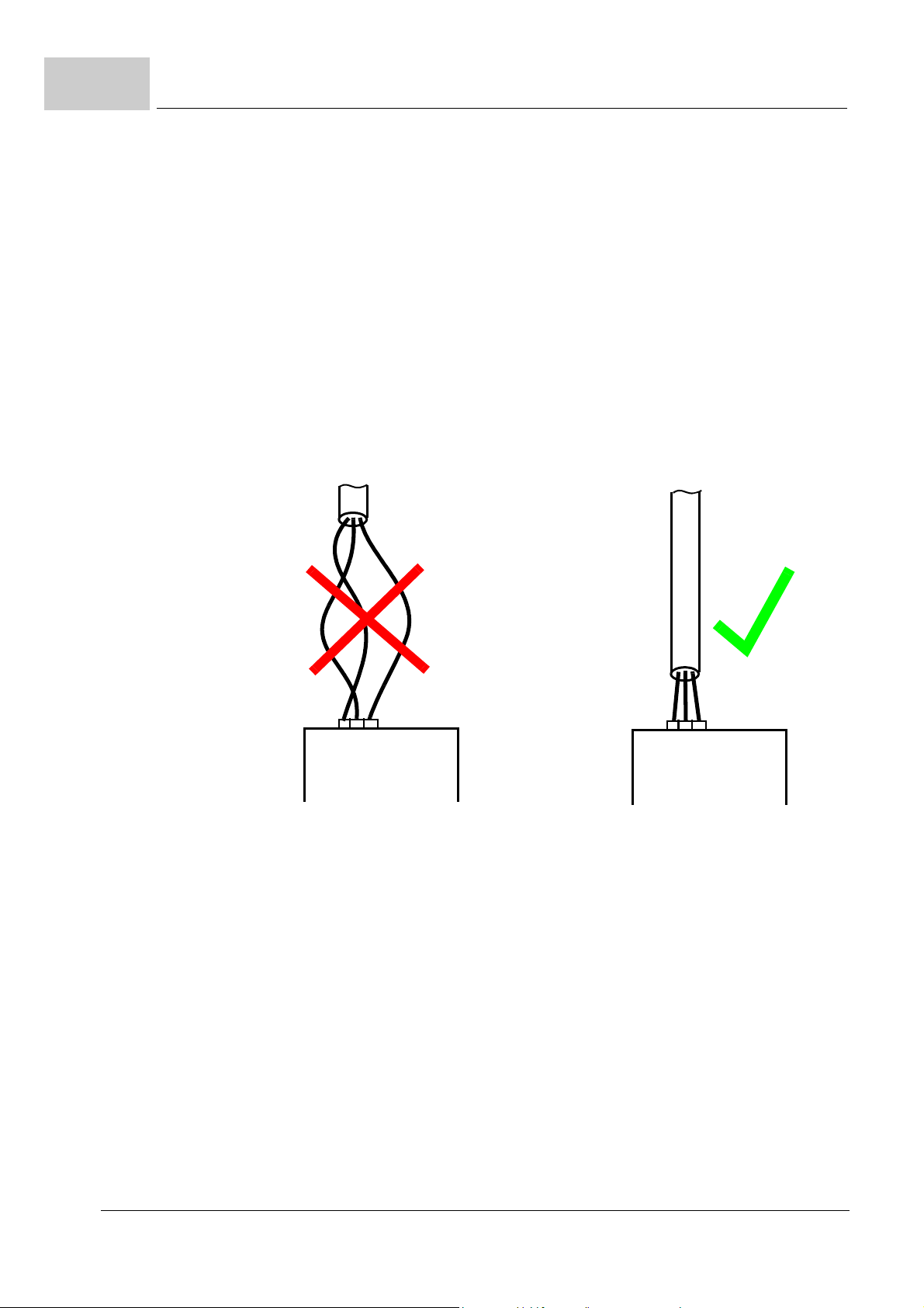
Short-circuit in
r cables
powe
In case of a short-circuit high current flows. This current induces a magnetic field in cable
loops. The magnetic field can cause failures of the device.
To avoid additional damage in case of a sh
n The co
must be laid without loop.
nnection between power supply and device or between device and motor
ort-circuit in power cables,
Figure 1: Wiring of the power cables
Installation If a shielded cable is connected unshielded and this causes failure of the device/danger
Brake resistor
ection
conn
Communication
errors
18
of 328
to persons, the system manufacturer is responsible for.
The dissipation of the heat loss of the external brake resistor must be ensured.
Ensure that a failure of the device w
The safety notes of all further chapters of this documentation need to be carefully observed!
Instruction handbook b maXX 5000
Document No.: 5.09021.16 Baumüller Nürnberg GmbH
ill cause no danger to persons.
2.5 Responsibility of the operating company
The device is used in commercial areas. Thus, the proprietor of the device is subject to
the legal work safety regulations.
Along with the notes on work safety in these in
prevention and environmental protection regulations valid for the area of application of
this device must be complied with. Whereby:
e operating company must inform himself about the applicable work health and safe-
m Th
ty regulations and ascertain, in a hazard ass
arise from the special working conditions in the use area of the device. These must
then be implemented in the form of instruction handbook for operation of the device.
ese instruction handbook must be kept accessible to personnel working with the de-
m Th
vice at all times in the immediate vicinity of the device.
e specifications of the instruction handbook must be adhered to completely and
m Th
without exception.
e device may only be operated in a technically faultless and operationally safe con-
m Th
dition.
Safety
struction handbook, the safety, accident
essment, any additional hazards that could
2
2.6 Protective devices
BM50XX IP 20
BM517X IP 20, with a contact-isolated con-
BM519X IP 00
BM5323, BM5325 IP 20
BM5326, BM5327, BM5328,
BM5331, BM5332, BM5333
BM5334, BM5335 IP 20, with a contact-isolated con-
BM537X IP 00
IP code
nection in accordance with IP 20,
ot
herwise IP 10.
IP 10
nection in accordance with IP 20,
ot
herwise IP 10.
DANGER!
Risk of fatal injury from elec
There is an immediate risk of fatal injury if live electrical parts are contacted.
Therefore:
device must be in operated inside of a control cabinet that provides protection
m The
against direct contact of the devices and at least meets the requirements of
EN 61800-5-1, Chapter 4.2.3.3.
trical current!
Instruction handbook b maXX 5000
Document No.: 5.09021.16
19
of 328
2.7
Training of the personnel
2.7 Training of the personnel
WARNING!
Risk of injury due to insufficient qual
Improper handling can lead to significant personal injury and material damage.
Therefore:
tain activities can only be performed by the persons stated in the respective
m Cer
chapters of these instruction handbook.
In these instruction handbook, the following qualifications are stipulated for various areas
tivity:
of ac
ifications!
m Oper
m Qualified
ating personnel
n The d
n Tro
n Initial operation
n Ele
n Qua
rive system may only be operated by persons who have been specially trained,
familiarized and authorized.
ubleshooting, maintenance, cleaning, maintenance and replacement may only
be performed by trained or familiarized personnel. These persons must be familiar
with the instruction handbook and act accordingly.
and familiarization may only be performed by qualified personnel.
personnel
ctrical engineers authorized by Baumüller Nürnberg GmbH, and qualified electri-
cians of the customer or a third party who have learned to install and maintain
umüller drive systems and are authorized to ground and identify electrical power
Ba
circuits and devices in accordance with the safety engineering standards of the company.
lified personnel have had occupational training or instruction in accordance with
the respective locally applicable safety engineering standards for the upkeep and
use of appropriate safety equipment.
20
of 328
Instruction handbook b maXX 5000
Document No.: 5.09021.16 Baumüller Nürnberg GmbH
2.8 Personal protective equipment
The wearing of personal protective equipment is required when working in order to minimize health and safety risks.
e protective equipment necessary for each respective type of work shall always be
m Th
worn during work.
e personal safety signs present in each working area must be observed.
m Th
Protective work clothing
should be snug-fitting work clothes, with
with no extending parts. It serves to primarily protect against...
No rings or chains should be worn.
Hard hat
to protect against falling down and flying around objects.
Safety
low tearing resistance, narrow sleeves and
2
Wear for special
rk.
wo
Safety shoes
to protect against heavy objects falling
Protective gloves
to protect hands against friction, abrasion, punctur
as contact with hot objects.
Protective eye wear
to protect the eyes against flying around objects and sprayed liquids.
down.
ing or more severe injuries, as well
Instruction handbook b maXX 5000
Document No.: 5.09021.16
21
of 328

2.9
Special hazards
2.9 Special hazards
In the following section, the remaining marginal risks will be stated that have been identified as a result of the hazard
Observe the safety notes listed here and the warning notes in the further chapters of this
truction handbook to reduce health risks and dangerous situations.
Ins
Electrical current
DANGER!
Risk of fatal injury from electrical current!
There is an immediate risk of fatal injury if live
to the insulation or individual components can be life-threatening.
Therefore:
m Switch
m Only
m Switch
analysis.
electrical parts are contacted. Damage
off the electrical power immediately in case of damage to the power supply
insulation.
allow work on the electrical system to be performed by qualified personnel.
off the current when any kind of work is being performed on the electrical
system and ensure safety before switching on again.
Danger from residual energy
DANGER!
Risk of fatal injury from electrical current!
Stored electric charge.
Discharge time of the rack system = discharge time
link discharge time in the rack system.
Refer to ZElec
Therefore:
m Do no
the capacitors.
y attention to the corresponding notes on the device.
m Pa
m If ad
ditional capacitors are connected to the DC link, the DC link discharge can
take a much longer time. In this case, the necessary waiting period must itself be
determined or a measurement made as to whether the equipment is de-energized.
This discharge time must be posted, together with an IEC 60417-5036 (2002-10)
warning symbol, on a clearly visible location of the control cabinet.
trical data– as from page 58.
t touch electrically live parts before taking into account the discharge time of
of the device with the longest DC
22
of 328
Instruction handbook b maXX 5000
Document No.: 5.09021.16 Baumüller Nürnberg GmbH

Moving components
2.10 Fire fighting
Safety
WARNING!
Risk of injury from moving components!
Rotating components and/or components moving linearly can result in severe injury.
Therefore:
not touch moving components during operation.
m Do
m Do
not open any covering during operation.
m The
amount of residual mechanical energy depends on the application. Powered
components still turn/move for a certain length of time even after the power supply
has been switched off. Ensure that adequate safety measures are taken.
2
DANGER!
Risk of fatal injury from electrical current!
There is a risk of electric shock if an electrically-c
is used.
Therefore:
the following fire-extinguishing agent:
m Use
ABC powder / CO
2
onductive, fire-extinguishing agent
Instruction handbook b maXX 5000
Document No.: 5.09021.16
23
of 328
2.11
Safety equipment
2.11 Safety equipment
WARNING!
Risk of fatal injury due to non-functional safety equipment!
Safety equipment provides for the highes
equipment makes work processes more awkward, under no circumstances may they
be circumvented. Safety can only be ensured by intact safety equipment.
Therefore:
fore starting to work, check whether the safety equipment in good working order
m Be
and properly installed.
2.12 Conduct in case of danger or accidents
t level of safety in a facility. Even if safety
Preventive
measures
And if something
happen:
does
respond properly.
m Always be prepared for accidents or fire!
m Keep first-aid equipment (e.g. firs
accessible.
m Familiarize personnel
m Stop operation of the device immediately with an EMERGENCY Stop.
m In
itiate first aid measures.
m Evacu
m No
m Ala
m Keep ac
ate persons from the danger zone.
tify the responsible persons at the scene of operations.
rm medical personnel and/or the fire department.
cess routes clear for rescue vehicles.
with accident alarm, first aid and rescue equipment.
t-aid kits, blankets, etc.) and fire extinguishers readily
24
of 328
Instruction handbook b maXX 5000
Document No.: 5.09021.16 Baumüller Nürnberg GmbH

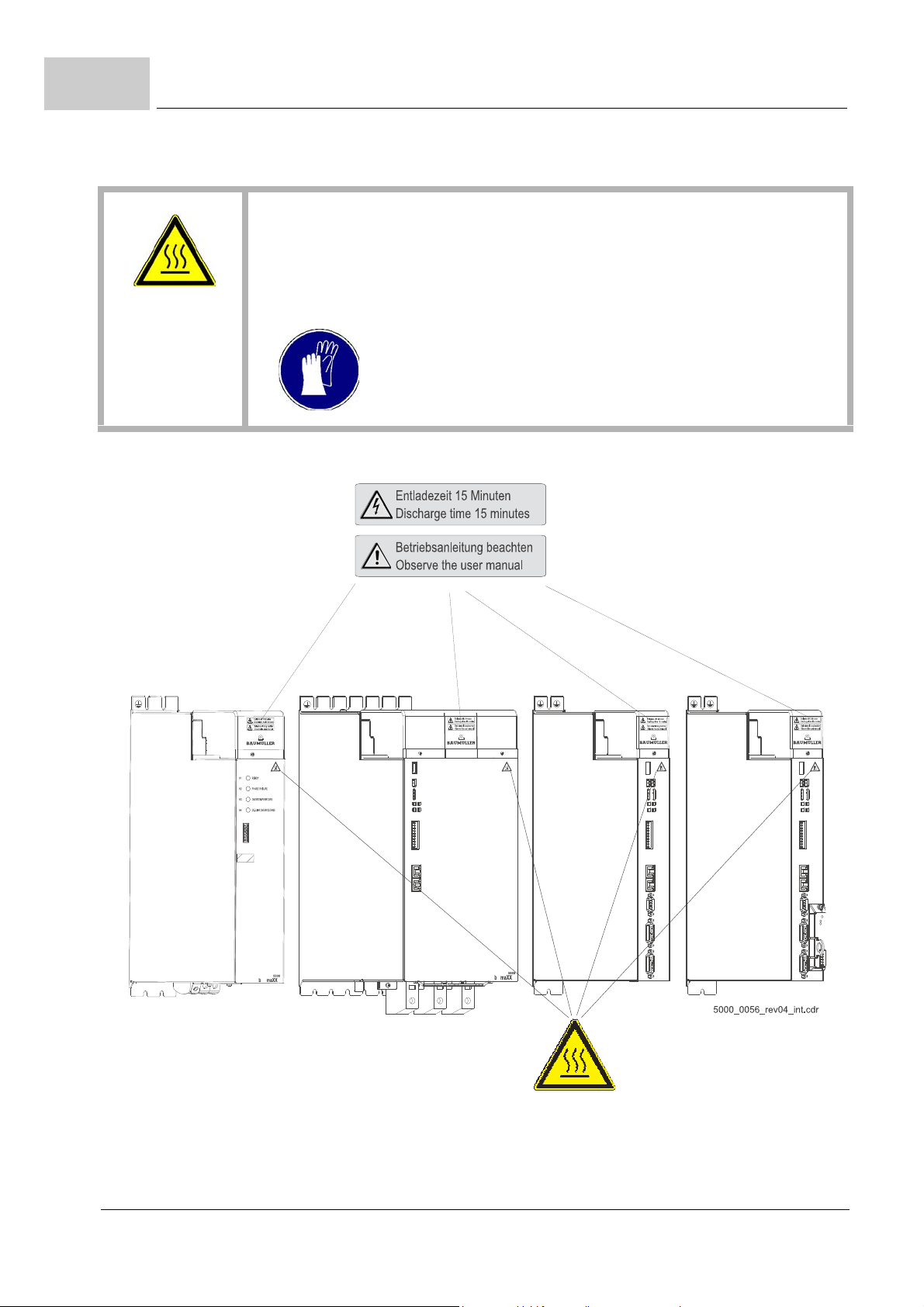
2.13 Signs and labels
The following symbols and information signs are located in the working area. They refer
to the immediate vicinity in which they are affixed.
WARNING!
Risk of injury due t
Over the course of time, stickers and symbols o
erwise unrecognizable.
Therefore:
m Main
condition.
Safety
o illegible symbols!
n the device can become dirty or oth-
tain all safety, warning and operating labels on the device in easily readable
2
Electrical voltage
Only qualified personnel may work in work areas that identified with this sign.
Unauthorized persons may not touch working ma
DANGER!
Risk of fatal injury from electrical current!
Stored electric charge.
Discharge time of the rack system = discharge t
link discharge time in the rack system.
Refer to ZElectrical da
Therefore:
o not touch before taking into account the discharge time of the capacitors and
m D
electrically live parts.
ed corresponding notes on the equipment.
m He
m If ad
ditional capacitors are connected to the DC link, the DC link discharge can
take a much longer time. In this case, the necessary waiting period must itself be
determined or a measurement made as to whether the equipment is de-energized.
This discharge time must be posted, together with an IEC 60417-5036 (2002-10)
warning symbol, on a clearly visible location of the control cabinet.
ta– as from page 58.
terials marked correspondingly.
ime of the device with the longest DC
Instruction handbook b maXX 5000
Document No.: 5.09021.16
25
of 328
2.13
Signs and labels
CAUTION!
Risk of injury due to hot surface!
When in operation, the top o
Therefore:
m Wea
r protective gloves
f the device can heat up to temperatures > 70 °C!
26
of 328
Figure 2: Signs and labels BM5XXX
Instruction handbook b maXX 5000
Document No.: 5.09021.16 Baumüller Nürnberg GmbH
Signs and labels
devices
with safety level
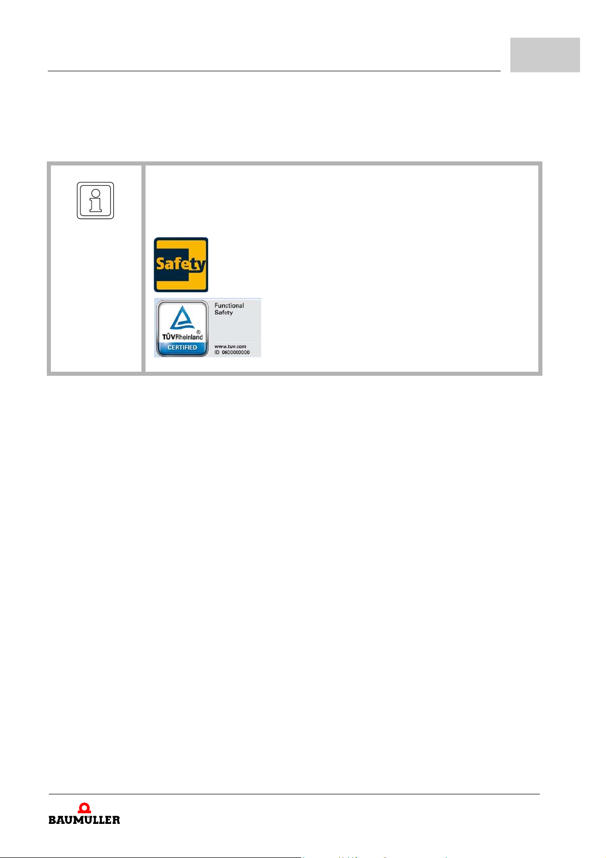
NOTE!
Safety
2
Only a device with built in Safety Module S
certification label and the safety label fulfills a certified safety function within the
meaning of PL classification according ISO 13849 or SIL according EN 61800.
AF XXX, marked with the TÜV Rheinland
Instruction handbook b maXX 5000
Document No.: 5.09021.16
27
of 328

2.13
Signs and labels
28
of 328
Instruction handbook b maXX 5000
Document No.: 5.09021.16 Baumüller Nürnberg GmbH
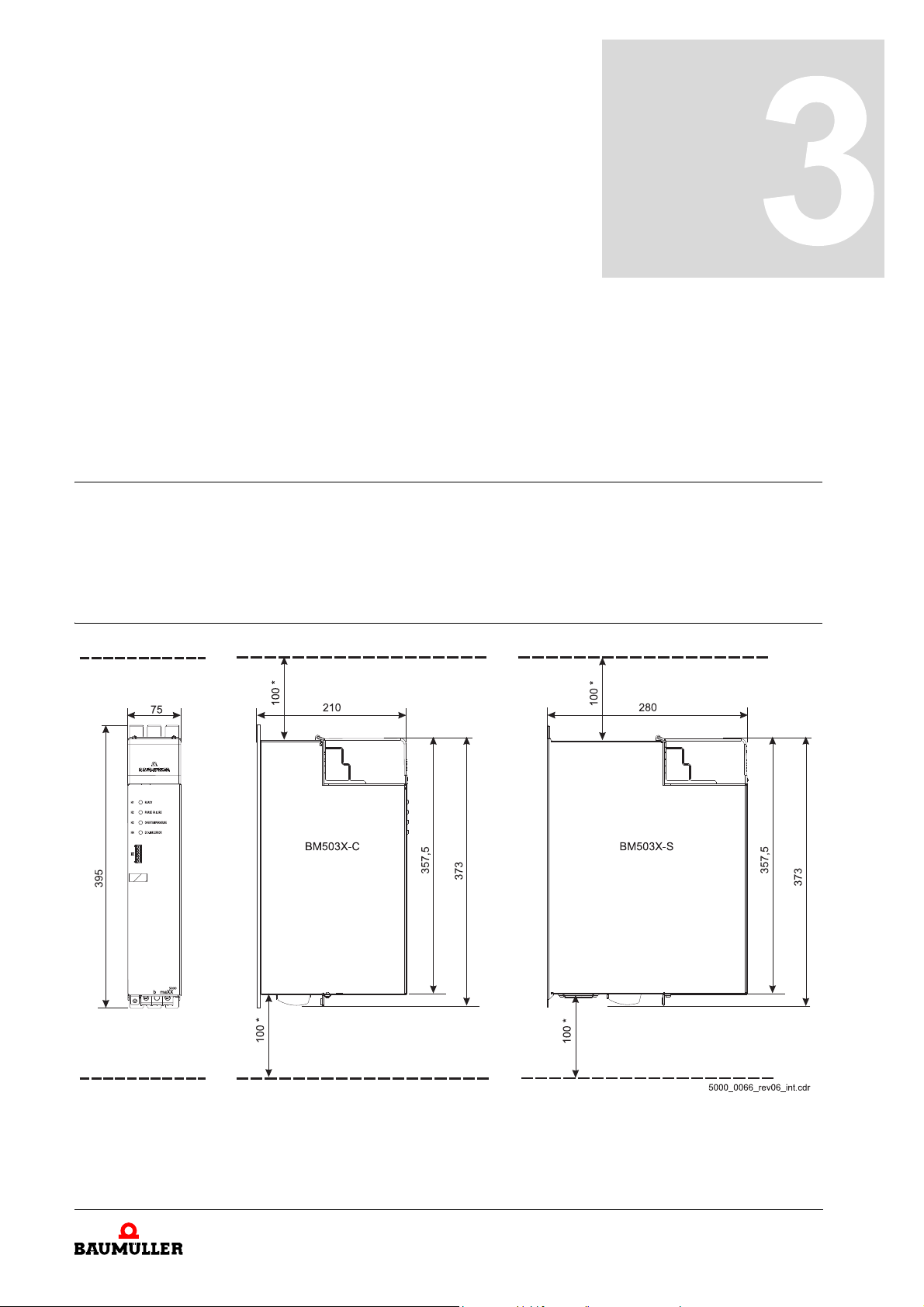
3.1 Dimensions
The following drawings show the main dimensions of the devices in millimeters [mm]. The
space requirements in the control cabinet are also determined based on these drawings.
To make the necessary drill holes/cutout sections, use the drawings in ZD
as from page 111.
3.1.1 BM503X dimensions
3TECHNICAL DATA
rilling pattern–
Figure 3: BM503X-C/-S dimensions
*: Observe minimum clearance.
Please follow the notes for mounting and
g– on page 56.
ZCoolin
Instruction handbook b maXX 5000
Document No.: 5.09021.16
29
of 328
395
373
357,5
100 *
100 *
75
210
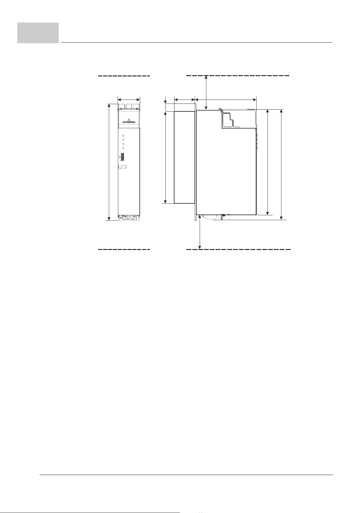
BM503X-A
READY
H1
H2
H3
H4
PHASEFAILURE
OVERTEMPERATURE
DC-LINKERROR
b maXX
5000
309 26
68
3.1
Dimensions
Figure 4: BM503X-A dimensions
*: Observe minimum clearance.
Please follow the notes for mounting and ZCooling– on
page 56.
30
of 328
Instruction handbook b maXX 5000
Document No.: 5.09021.16 Baumüller Nürnberg GmbH

3.1.2 BM504X dimensions
Technical data
3
Figure 5: BM504X-C/-S dimensions
*: Observe minimum clearance.
Please follow the notes for mounting and
g– on page 56.
ZCoolin
Instruction handbook b maXX 5000
Document No.: 5.09021.16
31
of 328

3.1
Dimensions
Figure 6: BM504X-A dimensions
*: Observe minimum clearance.
Please follow the notes for mounting and
ooling– on page 56.
ZC
32
of 328
Instruction handbook b maXX 5000
Document No.: 5.09021.16 Baumüller Nürnberg GmbH

3.1.3 BM517X dimensions
Technical data
3
Figure 7: BM517X-C/-S dimensions
*: Observe minimum clearance.
Please follow the notes for mounting and
ling– on page 56.
ZCoo
Instruction handbook b maXX 5000
Document No.: 5.09021.16
33
of 328

3.1
BM519X-S
3.1.4 BM519X dimensions
Dimensions
Figure 8: BM519X-S dimensions
*: Observe minimum clearance.
Please follow the notes for mounting and ZCooling– o
n page 56.
34
of 328
Instruction handbook b maXX 5000
Document No.: 5.09021.16 Baumüller Nürnberg GmbH

Connection tube G1/2“
flat sealing screw joint
with anti-twist protection
BM519X-F
Technical data
3
Figure 9: BM519X-F dimensions
*: Observe minimum clearance.
Please follow the notes for mounting and ZC
ooling– on page 56.
Instruction handbook b maXX 5000
Document No.: 5.09021.16
35
of 328

3.1
3.1.5 BM53XX dimensions
Dimensions
36
of 328
Figure 10: BM532X-C/-S dimensions
Instruction handbook b maXX 5000
Document No.: 5.09021.16 Baumüller Nürnberg GmbH
*: Observe minimum clearance.
Please follow the notes for mounting and
oling– on page 56.
ZCo

Technical data
3
Figure 11: BM532X-A dimensions
*: Observe minimum clearance.
Please follow the notes for mounting and
ling– on page 56.
ZCoo
Instruction handbook b maXX 5000
Document No.: 5.09021.16
37
of 328

3.1
Dimensions
Figure 12: BM533X-C/-S dimensions
*: Observe minimum clearance.
Please follow the notes for mounting and
oling– on page 56.
ZCo
38
of 328
Instruction handbook b maXX 5000
Document No.: 5.09021.16 Baumüller Nürnberg GmbH

Technical data
3
Figure 13: BM533X-A dimensions
*: Observe minimum clearance.
Please follow the notes for mounting and
ling– on page 56.
ZCoo
Instruction handbook b maXX 5000
Document No.: 5.09021.16
39
of 328

BM533X-F
3.1
Dimensions
Figure 14: BM533X-F dimensions
*: Observe minimum clearance.
Please follow the notes for mounting and
oling– on page 56.
ZCo
40
of 328
Instruction handbook b maXX 5000
Document No.: 5.09021.16 Baumüller Nürnberg GmbH

BM537X-S
Technical data
3
Figure 15: BM537X-S dimensions
*: Observe minimum clearance.
Please follow the notes for mounting and
ling– on page 56.
ZCoo
Instruction handbook b maXX 5000
Document No.: 5.09021.16
41
of 328

BM537X-F
3.1
Dimensions
Figure 16: BM537X-F dimensions
*: Observe minimum clearance.
Please follow the notes for mounting and
ZCooling– on page
56.
42
of 328
Instruction handbook b maXX 5000
Document No.: 5.09021.16 Baumüller Nürnberg GmbH

3.2 Weight
Device Weight, with controller
Technical data
3
BM503
BM504
BM517
BM517
BM519
BM532
BM533
BM533
BM537
BM533
X Approx. 6 kg
X Approx. 7 kg
X S
X C
X Approx. 25.0 kg
X Approx. 5.5 kg
X
X F
X
X F
Approx. 12.5 kg
Approx. 10.0 kg
Approx. 6.5 kg
Approx. 13 kg
Instruction handbook b maXX 5000
Document No.: 5.09021.16
43
of 328

3.3
Operating conditions
3.3 Operating conditions
3.3.1 Requirements for power supply / mains supply system
Power supply mains BM50XX - XTXX / - XRXX
BM51XX - XTXX / - XRXX
BM50XX - XIXX /
BM50XX - XGXX /
Inductance
(sum of mains inductance
and mains chok
Mains inductance
e inductance)
7)
BM50XX - XT...
BM51XX - XT...
BM503X - XR.../XS.../XW...
BM504X - XR...
Rated power supply voltage/frequency
1) 2)
- XSXX Industrial system with not grounded or with
- XWXX Industrial system, with direct or low
/XI.../XG...
/XI.../XG...
/XS.../XW...
(UAC) device
Power supply voltage
Absolute minimum
Absolute maximum
Absolute frequency minimum
Absolute frequency maximum
1) 2)
(UAC) device
1) 2)
(UAC) device
5)
5)
6)
6)
Industrial system, with direct or low
impedance grounded neutral point
(TN system or TT system)
high impedance grounded neutral point
(IT system)
in addition TN or TT system
impedance grounded junction of phases
(grounded delta wye)
in addition TN system, TT or IT system
u
= 2.4 %
k min
= 4 %
u
k max
u
= 0.5 %
k min
3 x 400 V
50
/60 Hz
BM50XX 3 x 207 V
3 x 528 V / 50/60 Hz
BM51XX 3 x 360 V
3 x 528 V / 50/60 Hz
47 Hz
63 Hz
/ 50/60 Hz
/ 50/60 Hz
Overvoltage category
EN 61800-5-1, chapter 4.3.6
Harmonic frequencies (power supply voltage)
EN 61800-3, chapter 5.2.1, class 3
Power supply voltage asymmetry
EN 61000-2-4, table 1, Class 3
Commutation notches
EN 61800-3, chapter 5.2.1, class 3
Voltage drops
EN 61800-3:2004 and A1:2012 10 % to 80 %
Voltage changes/fluctuation
EN 61200-2-4, class 3
Max. short circuit current power supply
Control voltage
according to EN 61131-2:2008
44
of 328
3)
(UDC)
Instruction handbook b maXX 5000
Document No.: 5.09021.16 Baumüller Nürnberg GmbH
4)
III
THDU b 12 %
Max. 3 %
Notch depth < 40 %,
area < 250 % x degree
1)
+/-10 %
+10 % to -15 %, for a duration of b 1 min
50 000 A
+ 24 V -15 % / +20 %

Technical data
1)
In case of power supply failure ((0.9 - 0) x UAC for t > 0.1 s), the error „Power unit not ready-to-operate“ is generated.
2)
The rated voltage is 400 V. At an power supply voltage of less than 400 V the output power of the device is reduced, refer to correction
values at changed operation conditions ZC
3)
The control voltage must correspond to PELV (EN 61800-5-1, chapter 3.21) or SELV (EN 61800, chapter 3.35). With a control voltage
< 24 V the fan output is reduced. Thus, it could be necessar
is limited to 4 A (with fuses, in accordance with UL 248) and to a voltage of max. 30 V
4)
Only necessary to comply with UL 508C, refer to ZUL notes– as from page 88.
5)
Change speed of the mains frequency max. 1 Hz/s (EN 61000-2-4, Class 3)
6)
The connection and/or operation of a device with the identifier BM5XXX-XTXX on IT mains or grounded delta mains is not allowed.
7)
NOTE!
The distortion factor of the input cur
BM50XX-XR /XS /XW ,, is at least twice as m
The user has to check with the local power supplier whether
3.3.2 Requirements for control voltage / 24 V power supply
orrection values input voltage– on page 52.
y to reduce the output current. If UL 508C is being considered, the current
rent of following devices
uch the factor at operation with power choke.
.
DC
an operation without power choke is allowed.
3
Figure 17: Control voltage / 24 V power supply
The power supply unit for the 24 V voltage supplied must provide at least the rated output
that corresponds to the total 24 V power consumption of all dev
Instruction handbook b maXX 5000
Document No.: 5.09021.16
ices of the rack system.
45
of 328

3.3
3.3.3 Requirements for the motor
Operating conditions
The b maXX 5000 is designed to operate three phase current motors with a motor terminal voltage of 3 x 350 V (typical for servo motors from Baumüller) or 3 x 400 V (typical for
standard asynchronous motors and for customer-specific special motors from
Baumüller). The motors must be operated in a star connection. The rated DC link voltage
is 540
VDC. It can be expected that the DC link voltage increases to up to 780 V or 800 V
in brake operation. The connected motor must be designed to handle these DC link volt
ages.
If b maXX 5000 axis units are operated with a voltage-controlled DC link (e.g. BM51XX),
then the DC link voltage will be permanently (not only in brake operation)
between 640 V and 760 V. The connected motor must be designed to be operated at
these voltages in continuous operation.
It is also possible to operate the devices at lower voltages, e.g. 3 x 230 V. A prerequisite,
however, is that the three phase current motors used for operation with converters rated
for an DC link voltage of up to 800
data– as from page 58) remains unchanged.
Thus, only three phase current motors with U
cases as well.
V, as the brake resistor voltage (refer to ZElectrical
DC link, rated
540 V may be used in these
-
46
of 328
Instruction handbook b maXX 5000
Document No.: 5.09021.16 Baumüller Nürnberg GmbH

Technical data
3.3.4 Required environmental conditions
Transport temperature range - 25 °C to + 70 °C
3
Transport climate class (K)
EN 60721-3-2
2 K 3
Storage temperature range - 25 °C to + 55 °C
Storage climate class
EN 60721-3-1
1 K 4
Operating environment
BM50XX
BM517X
refer to ZM
BM519X
Industrial supply network C2
Industrial supply network C3
ounting of toroidal cores– as from page 119
Industrial supply network C3
Operating temperature range Min. 5 °C to max. 55 °C
(with derating above 40 °C)
Operating climate class
EN 60721-3-3
3 K 3
Installation altitude Up to 4000 m above MSL
(with derating above 1000 m)
Humidity (operating)
EN 60721-3-3
Relative humidity: 5 % to 85 % non-condensed,
and
absolute humidity: 1 g/m
3
to 25 g/m
1)
,
2)
2)
3
Ionizing and non-ionized radiation < measurable range
Vibration, shock and continuous shock
EN 61800-5-1, chapter 5.2.6.4 vibration test
Degree of contamination
EN 61800-5-1, table 6, tab. 2
1)
If used in areas according to the category C2 of IEC 61800-3:2012, additional measures might be necessary. In this case the plant
manufacturer / user has to provide evidence these additional measures take effect and the in IEC 61800-3 required thresholds of the
category C2 are met.
2)
Refer to correction values at changed operation conditions at ZCorrection values at changed operating conditions– on page 48.
Max. 0.5 g when operating
2
NOTICE!
Normally only a non-conductive dirt buildup
occurs. Any conductive dirt buildup,
whether short-term or permanent, is prohibited and could lead to destruction of the
device. The customer is responsible for destruction resulting from dirt buildup of conductive materials or matter.
Instruction handbook b maXX 5000
Document No.: 5.09021.16
47
of 328

3.3
3.3.5 Correction values at changed operating conditions
Operating conditions
The correction values of the permitted output power and output current must be multiplied, if the devices b maXX 50
tion values.
The following correction values are to be considered if
„Electrical data“ of the device:
NOTE!
Baumüller devices that are intended for operation in grounded delta mains or IT
ains may only be operated in those types of mains up to an installation altitude of
m
2000 m above MSL. At an installation altitude of 2000 m and higher these devices are
operated in TN and TT mains. Power supply of this type can be accomplished
to be
by using an isolating transformer with a secondary-side grounded neutral point, for
example.
00 are used at operation conditions with different correc-
nothing other is specified at the
NOTE!
The temperature of the water cooler or the cold plate temperature must be higher or
equal to the surrounding temperature to prevent condensation.
48
of 328
Instruction handbook b maXX 5000
Document No.: 5.09021.16 Baumüller Nürnberg GmbH

Technical data
0%
20%
40%
60%
80%
100%
120%
0m 1.000m 2.000m 3.000m 4.000m 5.000m
Output current I
permitted
Output rated current I
rated
1,0
0,8
0,6
0,4
0,2
Installation altitude
k
H
Correction value installation altitude k
H
k
T
1
Coolant temperature - 40 °C
°C
---------------------------------------------------------------------------------
0,03
–=
I
permitted
I
rated
kTk
H
=
3.3.5.1 Correction values for the output current of the mains inverter BM50XX, BM51XX
3
Installation
altitude
If the devices BM50XX, BM51XX are operated above an absolute altitude of 1000 m,
then the permitted output current I
permitted
duced against the output rated current (see ZElec
(adjusted output rated current) must be re-
trical data BM50XX; BM51XX– as from
page 58) according to the following curve.
Figure 18: Correction value kH in dependence on the installation altitude H, BM50XX, BM51XX
Operating
temperature
The devices BM50XX, BM51XX were designed to be operated at an operating temperature of T
55 °C the permitted output current (I
= 40 °C. If the devices are operated at temperatures between 40 °C and
rated
permitted
) must be reduced:
The coolant temperature complies with the environmental temperature of air-cooled devices, with the water temperature of water-coo
led devices and the surface temperature of
the cold plate/mounting panel of devices with cold plate cooling.
The permitted output current I
permitted
(adjusted output rated current) is calculated accord-
ing following formula:
I
= Output rated current at 40 °C and up to 1000 m,,
rated
see ZElectrical
data BM50XX; BM51XX– as from page 58.
Instruction handbook b maXX 5000
Document No.: 5.09021.16
49
of 328

3.3
Operating temperature T
U
k
T
Correction value operating temperature
Air-cooled
Water-cooled/Cold plate
Installation altitude H
k
H
Correction value installation altitude
3.3.5.2 Correction values for the output current of the axis units BM53XX
Operating conditions
Figure 19: Correction value kT in dependence of the temperature TU, BM53XX
Figure 20: Correction value kH in dependence on the installation altitude H, BM53XX
50
of 328
Instruction handbook b maXX 5000
Document No.: 5.09021.16 Baumüller Nürnberg GmbH

Technical data
I
permitted
I
ratedkTkH
=
kTkH0,79
3
The permitted output current I
permitted
(adjusted output rated current) is calculated accord-
ing following formula:
I
= Output rated current at 40 °C and up to 1000 m,
rated
refer to ZElectr
. kH > 1, then I
If k
T
permitted
an output current higher than I
ical data of the BM53XX– as from page 66.
= I
,
rated
is not possible.
rated
NOTICE!
The following condition must always be met to prevent the device of overload:
Examples: k
If kT . kH > 1, the operation of the device is permitted and I
T (25 °C)
k
H (3000 m)
k
T (25 °C)
k
T (20 °C)
k
H (1500 m)
k
T (20 °C)
k
T (40 °C)
k
H (4000 m)
k
T (40 °C)
= 1.2
= 0.8
* k
H (3000 m)
= 1.27
= 0.95
* k
H (1500 m)
= 1
= 0.7
* k
H (4000 m)
= 0.96 0.79 Operation permitted
I
permitted
= I
= 1.20 0.79 Operation permitted
I
permitted
= I
= 0.7 < 0.79 Operation not permitted
rated
rated
permitted
. 0.96
is limited to I
rated
.
Instruction handbook b maXX 5000
Document No.: 5.09021.16
51
of 328

3.3
180 V 400 V 528 V
100 %
50 %
Operating conditions
3.3.5.3 Correction values input voltage
Above
rated power
supply voltage
m Mains rectifier units BM503X, BM504X, BM517X, BM519X
The rated power supply v
The output currents must be reduced accordingly
oltage is 3 x 400 V
when operating with a power supply
voltage higher than 400 V.
Output current
Power supply voltage
Figure 21: Derating: Output current as a function of the power supply voltage
The device draws the rated/peak current at rated supply voltage. The input current must
be reduced if power supply voltage is higher than 400 V and the DC link output power remains constant.
Peak current
Input current [%]
Max. continuous
rent
cur
Supply voltage [V]
Figure 22: Derating: Input current BM503X, BM504X, BM517X, BM519X
52
of 328
Instruction handbook b maXX 5000
Document No.: 5.09021.16 Baumüller Nürnberg GmbH

Technical data
207 V
400 V
528 V
100 %
51 %
3
Below
rated input
voltage
m Mains rectifier units BM503X, BM504X, BM517X, BM519X
The rated voltage is 3 x 400 V
The DC link voltage must be reduced when o
DC link voltage device
Figure 23: Derating: DC link voltage as a function of the power supply voltage
m Mains rectifier units BM503X, BM504X, BM517X BM519X
perating with input voltage lower than 400 V.
Power supply voltage
Output power
P
rated
Continuous operation
permitted
Output power device
Power supply voltage
Figure 24: Derating: Output power as a function of the power supply voltage
The output power of the device is calculated by multiplying the output current
and the output voltage.
S
= U
out
It is necessary to reduce the output current between 400 V and 528 V in order
to comply with the curve/area.
out
x I
out
x 3
Instruction handbook b maXX 5000
Document No.: 5.09021.16
53
of 328

3.3
207 V
400 V
528 V
100 %
51 %
Operating conditions
Below
rated input
voltage
m Mains rectifier units BM517X, BM519X
The rated voltage is 3 x 400 V
The DC link voltage must be reduced when op
erating with input voltage lower than 400 V.
DC link voltage device
Power supply voltage
Figure 25: Derating: DC link voltage as a function of the power supply voltage
P
rated
Continuous operation
permitted
Output power device
Power supply voltage
Figure 26: Derating: Output power as a function of the power supply voltage
The output power of the device is calculated by multiplying the output current
and the output voltage.
S
= U
x I
out
out
out
x 3
It is necessary to reduce the output current between 400 V and 528 V in order
to comply with the curve/area.
54
of 328
Instruction handbook b maXX 5000
Document No.: 5.09021.16 Baumüller Nürnberg GmbH

3.3.5.4 Correction values DC link voltage
400
480
--------- - 0 833=
Technical data
3
Mains rectifier
BM503X,
BM504X,
BM517X,
BM519X
With the permissible continuous DC link power, the power supply current, e.g. with a
power supply voltage of 480 V
(instead of 31 A
When selecting the connected axes ensure that the DC link power is not exceeded.
DC link power [%]
Figure 27: Derating: DC link power B503X, BM504X, BM517X, BM519X
the power supply current is then 25.8 AAC).
AC
, is less by a ratio
AC
Power supply voltage [V]
Axis units
BM53XX
Output current [%]
The axis units supply the rated/peak currents at rated DC link voltage. The output currents
must be reduced accordingly when operating with a DC link voltage is higher than 640 V
d output power remains constant.
an
DC link voltage [V]
Figure 28: Derating: Output current as function of the D
C link voltage axis units
Instruction handbook b maXX 5000
Document No.: 5.09021.16
55
of 328

3.3
14 35
l/min
kW
------------
K
power loss kW
coolant flow [l/min]
-------------------------------------------------
Operating conditions
3.3.6 Cooling
Cooling air temperature
1)
Min. 5 °C to max. 55 °C
(rated temperature: 40 °C),
ge 49–
Cooling air requirement
Coolant temperature
4)
refer to correction values temperature Zpa
2)
Depends on the device, refer to ZElectrical data– as from page 58
Min. surrounding temperature up to max. 55 °C
(rated temperature: 40 °C),
age 49–
Coolant flow
3)
Coolant pressure
refer to correction values temperature Zp
Min. 4 l/min. to max. 15 l/min
3)
Max. 6 bar
Coolant hysteresis Max. 5 K in static and dynamic operation
Water heating
(coolant in to coolant out)
Pressure drop
at the water cooling unit
Surface temperature
Cold plate / mounting base
3)
[K]
0.5 bar at 10 l/min
3)
4) 5)
Min. surrounding temperature up to max. 55 °C
(rated temperature: 40 °C),
refer to correction values temperature Zpa
ge 49–
1)
Air temperature in the entire intake area of the device.
2)
The cooling air requirement corresponds to at least that of a freely-blowing device. Freely-blowing means that the air flow in and out are
unobstructed. Therefore, when installing the device in a control cabinet, it could be necessary to make use of additional fans in order
that the necessary cooling air requirement is covered. If the necessary cooling air requirement of the passive cooling unit is not provided
for, then the output power of the device must be reduced.
Figure 29: Cooling air requirement
56
of 328
Instruction handbook b maXX 5000
Document No.: 5.09021.16 Baumüller Nürnberg GmbH

Technical data
3)
Rated flow rate = 10 l/min
For other coolant flow rates than the one stated above, please inq
The coolant must meet the following requirements:
pH value 6.5 ... 9.5 Manganese (Mn) < 0.05 ppm
Conductivity 50 ... 600 µS/cm Copper (Cu) < 0.1 ppm
Total water hardness (incl. CaCO
Suspended matter < 10 ppm Chloride (Cl
Particle size < 100 µm Sulfate (SO
Ryznar Stability Index (RSI) 5.0 ... 6.0
The corrosion resistance to other substances can be seen in the D
An anti-corrosion agent and a closed cooling circuit are prescribed.
4)
The surface temperature of the water cooler or cold plate must be higher or the same as the device interior temperature
to prevent condensation always.
In case of surface temperatures other than those specified, please
5)
Notes relating to cold plate
The cooling version cold plate is a particular efficient cooling alternative. The heat dissipation is done via 2 contact surfaces. The mounting platform within the control cabinet or
mounted there. High requirements e.g. to surface roughness and evenness for this surface are specified, to ensure an
optimal heat flow. Already a slight damage/pollution of the surface can cause a significant deterioration in heat dissipation
to the mounting plate.
For this reason while handle the units protect the sensitive fun
6)
By means of the thermal resistance of the cooling system and the thermal power loss, which is supplied to the cooling system, the surface temperature can be calculated.
) < 100 ppm Chlorine (Cl2) < 1 ppm
3
uire with Baumüller Nürnberg GmbH.
-
) < 500 ppm
2-
) < 500 ppm
4
ECHEMA material tables.
inquire with Baumüller Nürnberg GmbH.
on the machine base is one, the device, to be cooled is
ction surface to avoid damage and pollution.
3
Instruction handbook b maXX 5000
Document No.: 5.09021.16
57
of 328

3.4
Electrical data
3.4 Electrical data
3.4.1 Electrical data BM50XX; BM51XX
m BM5030 mains rectifier unit without safety function
BM5030
-XT0X-.. /-XI0X-..
without charge resistor
Input rated power
Input rated current (I
Distortion factor of the input current (THD
Input peak current (I
1)
eff
eff
1) 2) 3)
)
1) 2) 3)
)
6 kVA 6.9 kVA
8.5 A 10.4 A
1)
)
I
57 % ± 10 % 160 % ± 10 %
12.5 A for max. 150 s 15.6 A for max. 150 s
DC link voltage, power supply dependent/rated 540 V
Internal DC link capacitance (C
DC link discharge time (C
int
) 470 µF
int
9)
)
Waiting period between 2 charging processes
(no external DC link capacitance)
Total maximum connectable capacitance in the
D
C link
Waiting time between 2 charging processes
with maximum capacitance
Connection power at DC link
Peak power at DC link
1) 5)
4) 6)
/ -XG0X-..
-XR0X-.. /-XS0X-.. / -XW0X-..
with charge resistor
DC
at U
power supply
= 3 x 400 V
Approx. 450 s
36 s
7.8 mF
internal + external
13)
600 s
5 kW
7.5 kW for max. 150 s
BM5030
14)
Ready-to-operate after 7 s
Max. charge-up time 10 s
External brake resistor R
B
RB 33
External brake resistor continuous power 5 kW
Quick discharge resistor -
Power loss with regard to power supply
Power loss with regard to cont
supply
8)
rol voltage
Cooling air requirement power heat sink 40 m
7)
40 W
Max. 10 W
3
Cooling air velocity power heat sink -
Cooling air requirement internal space of device 8 m
Footnotes refer to Zpage 65–.
3
/h
/h
58
of 328
Instruction handbook b maXX 5000
Document No.: 5.09021.16 Baumüller Nürnberg GmbH

m BM5030 mains rectifier unit with safety function
NOTE!
Technical data
3
Description of BM5030 with safety function BM
refer to ZC.3
m BM50
Electrical data BM5030 with safety function– as from page 304.
3X mains rectifier unit without safety function
5030-XX2X-...
BM5031 BM5031-A BM5031 BM5031-A
-XT0X-..
/-XI0X-.. / -XG0X-..
-XR0X-.. /-XS0X-.. / -XW0X-..
without charge resistor
Input rated power
Input rated current (I
Distortion factor of the
Input peak current (I
DC link voltage
1)
1) 2) 3)
)
eff
input current (THDI)
1) 2) 3)
)
eff
12 kVA 17.5 kVA
17 A 25 A
1)
57 % ± 10 % 180 % ± 10 %
25 A for max. 150 s 37.5 A for max. 150 s
540 V
DC
at U
supply
power supply dependent/rated
DC link capacitance (internal) 940 µF
DC link discharge time
(internal DC link capacitance)
9)
Approx. 450 s
with charge resistor
14)
= 3 x 400 V
Total max. connectible capacitance in the
20 mF
DC link (internal + external)
4) 6)
1) 5)
10 kW 18 kW
15 kW for max. 150 s 27 kW for max. 150 s
Connection power at DC link
Peak power at DC link
Ready-to-operate after 7 s
Max. charge-up time 10 s
Quick discharge
External brake resistor R
10)
5 s
B
RB 33
External brake resistor continuous power 18 kW
Quick discharge resistor -
Power loss with regard to power supply
Power loss with regard to control voltage
supply
8)
Cooling air requirement power heat sink 40 m
7)
40 W 80 W
Max. 10 W
3
/h - 40 m3/h -
Cooling air velocity power heat sink - > 5 m/s - > 5 m/s
Cooling air requirement internal space of
de
vice
8 m3/h
Footnotes refer to Zpage 65–.
Instruction handbook b maXX 5000
Document No.: 5.09021.16
59
of 328

3.4
Electrical data
m BM503X mains rectifier unit without safety function
BM5032 BM5032
-XT0X-.
. /-XI0X-.. / -XG0X-..
without charge resistor
Input rated power
Input rated current (I
Distortion factor of the input current (THD
Input peak current (I
DC link voltage
1)
1) 2) 3)
)
eff
1)
)
I
1) 2) 3)
)
eff
540 V
21 kVA
31 A
57 % ± 10 %
46 A for max. 150 s
at U
DC
Supply
power supply dependent/rated
DC link capacitance (internal) 940 µF
DC link discharge time
(internal DC link capacitance)
9)
Total max. connectible capacitance in the
ca. 450 s
20 mF
DC link (internal + external)
4) 6)
1) 5)
18 kW
27 kW for max. 150 s
Connection power at DC link
Peak power at DC link
Ready-to-operate after 7 s
Max. charge-up time 10 s
Quick discharge
10)
5 s
-A
= 3 x 400 V
External brake resistor R
B
RB 33
External brake resistor continuous power 18 kW
Quick discharge resistor -
Power loss with regard to power supply
Power loss with regard to
control voltage supply
8)
Cooling air requirement power heat sink 40 m
7)
80 W
Max. 10 W
3
/h -
Cooling air velocity power heat sink - > 5 m/s
Cooling air requirement
8 m3/h
internal space of device
Footnotes refer to Zpage 65–.
60
of 328
Instruction handbook b maXX 5000
Document No.: 5.09021.16 Baumüller Nürnberg GmbH

m BM504X mains rectifier unit without safety function
Technical data
3
BM5043 BM5043
-XT0X-.. /-XI0X-.. / -XG0X-..
-A BM5043 BM5043-A
-XR0X-.. /-XS0X-..
without charge resistor
Input rated power
Input rated current (I
Distortion factor of the
Input peak current (I
DC link voltage
1)
1) 2) 3)
)
eff
input current (THDI)
1) 2) 3)
)
eff
45 kVA 61 kVA
65 A 88 A
1)
57 % ± 10 % 180 % ± 10 %
98 A for max. 150 s 132 A for max. 150 s
540 V
DC
at U
power supply
power supply dependent/rated
DC link capacitance (internal) 1000 µF
DC link discharge time
(internal DC link capacitance)
9)
Total max. connectable capacitance
Approx. 350 s
20 mF
in the DC link (internal + external)
4) 6)
1) 5)
36 kW
54 kW for max. 150 s
Connection power at DC link
Peak power at DC link
Ready-to-operate after 7 s
Max. charge-up time 10 s
Quick discharge
10)
5 s
/ -XW0X-..
with charge resistor
14)
= 3 x 400 V
External brake resistor R
B
RB 10.5
External brake resistor continuous power 58 kW
Quick discharge resistor -
Power loss with regard to power supply
Power loss with regard to control
voltage supply
8)
Cooling air requirement power heat sink 100 m
7)
190 W
Max. 25 W
3
/h - 100 m3/h -
Cooling air velocity power heat sink - > 5 m/s - > 5 m/s
Cooling air requirement
8 m
3
/h
internal space of device
Footnotes refer to Zpage 65–.
Instruction handbook b maXX 5000
Document No.: 5.09021.16
61
of 328

3.4
Electrical data
m BM504X mains rectifier unit without safety function
BM5044 BM5044
-XT0X-..
/-XI0X-.. / -XG0X-..
without charge resistor
Input rated power
Input rated current (I
Distortion factor of the input current (THD
Input peak current (I
DC link voltage
1)
1) 2) 3)
)
eff
1)
)
I
1) 2) 3)
)
eff
540 V
DC
90 kVA
130 A
57 % ± 10 %
No overload
at U
power supply
power supply dependent/rated
DC link capacitance (internal) 1000 µF
DC link discharge time
(internal DC link capacitance)
9)
Total max. connectable capacitance
Approx. 350 s
20 mF
in the DC link (internal + external)
4) 6)
1) 5)
70 kW
No overload
Connection power at DC link
Peak power at DC link
Ready-to-operate after 7 s
Max. charge-up time 10 s
Quick discharge
10)
5 s
-A
= 3 x 400 V
External brake resistor R
B
RB 10.5
External brake resistor continuous power 58 kW
Quick discharge resistor -
Power loss with regard to power supply
Power loss with regard to
control voltage supply
8)
Cooling air requirement power heat sink 100 m
7)
390 W
Max. 25 W
3
/h -
Cooling air velocity power heat sink - > 5 m/s
Cooling air requirement
8 m
3
/h
internal space of device
Footnotes refer to Zpage 65–.
62
of 328
Instruction handbook b maXX 5000
Document No.: 5.09021.16 Baumüller Nürnberg GmbH

m BM517X active mains rectifier unit
Technical data
3
3 BM5174
-XTXX-.
. /-XIXX-.. / -XGXX-..
39 kVA 69 kVA
56 A 100 A
6 %
84 A
11)
8 kHz
640 V
to 760 V
DC
Input rated power
Input rated current (I
Distortion factor of the
Input peak current (I
1)
1) 2) 3)
)
eff
input current (THDI)
1) 2) 3)
)
eff
PWM switching frequency
DC link voltage
BM517
1)
for max. 120 s
power supply dependent/rated
DC link capacitance (internal) 2.5 mF
DC link discharge time
(internal DC link capacitance)
9)
Total max. connectable capacitance
Approx. 600 s
20 mF
in the DC link (internal + external)
4) 6)
1) 5)
36 kW 64 kW
54 kW
for max. 120 s
11)
Connection power at DC link
Peak power at DC link
Power factor (inductive only) 0.9 bis 1.0
150 A
for max. 120 s
12)
DC
96 kW
for max. 120 s
11)
11)
Ready-to-operate after 50 s
Max. charge-up time 10 s
Quick discharge
External brake resistor R
10)
5 s
B
Quick discharge resistor 55 R 72
Power loss with regard to power supply
Power loss with regard to
control voltage supply
8)
Cooling air requirement power heat sink 175 m
7)
900 W 1600 W
Max. 60 W
3
/h
Cooling air velocity power heat sink Cooling air requirement
35 m
3
/h
internal space of device
Footnotes refer to Zpage 65–.
Instruction handbook b maXX 5000
Document No.: 5.09021.16
63
of 328

3.4
Electrical data
m BM519X active mains rectifier unit
BM519
2-S BM5192-F BM5193-F
-XTXX-.. /-XIXX-.. /
Input rated power
Input rated current (I
Distortion factor of the input current (THD
Input peak current (I
PWM switching frequency
DC link voltage
1)
1) 2) 3)
)
eff
1)
)
I
1) 2) 3)
)
eff
150 kVA 200 kVA
220 A 290 A
6 %
435 A
for max. 10 s
8 kHz
640 V
to 760 V
DC
power supply dependent/rated
DC link capacitance (internal) 7.5 mF
DC link discharge time
(internal DC link capacitance)
Total max. connectable cap
acitance in the DC link
9)
Approx. 600 s
100 mF
(internal + external)
4) 6)
1) 5)
150 kW 200 kW
300 kW
for max. 10 s
Connection power at DC link
Peak power at DC link
Power factor (inductive only) 0.9 bis 1.0
-XGXX-..
14)
DC
435 A
for max. 10 s
Ready-to-operate after 50 s
Max. charge-up time 10 s
Quick discharge
External brake resistor R
10)
5 s
B
Quick discharge resistor R 10
Power loss with regard to power supply
Power loss with regard to control voltage supply
Footnotes refer to Zpage 65–.
7)
8)
Max. 100 W Max. 60 W
2500 W 3300 W
64
of 328
Instruction handbook b maXX 5000
Document No.: 5.09021.16 Baumüller Nürnberg GmbH

Technical data
1)
All rated values are based on an power supply voltage of 400 V/50 Hz, a DC link voltage of 540 V (BM50XX)
or 640 V (BM51XX), a control voltage of 24 V and a surrounding temperature of 40 °C.
2)
The input current must be reduced between 40 °C and 55 °C, refer to correction values at changed operation
conditions, ZCor
3)
The mains rectifier draws the rated/peak current at rated supply voltage. The input current must be reduced
if power supply voltage is higher than 400 V and the DC link output power remains constant, refer to ZDer-
ating: Input current BM503X, BM504X, BM517X, BM519X– on pa
4)
The actual possible overload time depends on the preloading of the device and the heat sink temperature
and is detected by the overload monitoring of the device.
5)
With the permissible continuous DC link connected power, the power supply current is reduced. When selecting the connected axes ensure that the DC link conne
link power B503X, BM504X, BM517X, BM519X– on page 55.
6)
This power consumption is only permitted for a short period of time. This must be ensured by means of appropriate configuration of the connected axes.
7)
Including external power choke
8)
Without loads on the digital outputs
9)
Residual voltage < 60 V
10)
It is necessary to connect a quick discharge resistor or a brake resistor!
11)
Cold plate version max. 30 s
For details refer to ZLoad cycle
12)
For further information refer to parameter 141.8 DC link voltage set value at parameter manual b maXX 5000
13)
Between the min. waiting time (internal DC link capacitance only) and the max. waiting time (maximum DC
link capacitance) can be linearly interpolated depending on the total capacitance value.
14)
Mains inductance u
rection values for the output current of the mains inverter BM50XX, BM51XX– on page 49.
ge 52.
cted power is not exceeded, refer to ZDerating: DC
DC
according EN61800-6– as from page 75
= 0,5 %
k min
3
NOTE!
The distortion factor of the input cur
BM50XX-XR /XS /XW ,, is at least twice as m
The user has to check with the local power supplier whether
rent of following devices
uch the factor at operation with power choke.
an operation without power choke is allowed.
Instruction handbook b maXX 5000
Document No.: 5.09021.16
65
of 328

3.4
Electrical data
3.4.2 Electrical data of the BM53XX
m Double axis unit safety
3 BM5323-A BM5325 BM5325-A
3.5 kW 5.75 kW 7.0 kW 9.9 kW
60 V - 760 V
Input rated power
DC link voltage (U
1) 9)
DC
BM532
1)
)
DC link capacitance (internal) 235 µF
DC link discharge time
250 s
(internal DC link capacitance)
1) 3)
Output voltage
(UAC)
Output frequency at 4 kHz
Output rated current
(I
AC
Output rated current
(I
AC
Output rated current
(I
AC
Output peak current
(I
AC
Output peak current
(I
AC
Output peak current
(I
AC
RMS)
RMS)
RMS)
RMS)
RMS)
RMS)
1) 2) 5)11)
1) 2) 5)11)
1) 2) 5)11)
1) 5) 6)11)
1) 5) 6)11)
1) 5) 6)11)
4)
at
4 kHz
at
8 kHz
at
16 kHz
at
4 kHz
at
8 kHz
at
16 kHz
4)
4)
4)
4)
4)
4)
2 x 3 A 2 x 4.5 A 2 x 6 A 2 x 8.5 A
2 x 2.1 A 2 x 3.15 A 2 x 4.2 A 2 x 5.9 A
2 x 9 A 2 x 18 A
2 x 6.3 A 2 x 12.6 A
0 - 500 V
0 - 450 Hz
-
-
Short-time operation KB 300 % 200 % 300 %
Max. length of time peak current
6)
Refer to ZLoad cycle accor
ding EN61800-6– as from page 75
Power loss with regard to power supply Max. 55 W Max. 82.5 W Max. 100 W Max. 141 W
Power loss with regard to
(air-cooled)
7)
Power loss with regard to
(cold plate cooling)
Current of the integrated brake control
Cooling air requirement power heat sink 15 m
control voltage supply
control voltage supply
7)
(option)
Max. 35 W
Max. 35 W
8)
3
/h - 15 m3/h -
Max. 2 x 2.0 A
Cooling air velocity power heat sink - > 5 m/s - > 5 m/s
Cooling air requirement internal space of device - 10 m
Footnotes refer to Zpage 73–.
66
of 328
Instruction handbook b maXX 5000
Document No.: 5.09021.16 Baumüller Nürnberg GmbH
3
/h
with cold plate
-

Technical data
BM5331 BM5331-A BM5332 BM5332-A BM5333 BM5333-A
Input rated po
DC link voltage (U
DC link capacitance (internal) 330 µF 660 µF 1175 µF
DC link discharge time
(internal DC link capacitance)
Output voltage
Output frequency at 4 kHz
wer
(UAC)
1) 9)
DC
)
1) 3)
13.4 kW 22.4 kW 33.6 kW
1)
60 V - 760 V
240 s 480 s 900 s
0 - 500 V
4)
0 - 450 Hz
3
Output rated current
(I
AC
Output rated current
(I
AC
Output rated current
(I
AC
Output peak current
(I
AC
Output peak current
(I
AC
Output peak current
(I
AC
RMS)
RMS)
RMS)
RMS)
RMS)
RMS)
1) 2) 5)11)
1) 2) 5)11)
1) 2) 5)11)
1) 5) 6)11)
1) 5) 6)11)
1) 5) 6)11)
at
4 kHz
at
8 kHz
at
16 kHz
at
4 kHz
at
8 kHz
at
16 kHz
4)
4)
4)
4)
4)
4)
2 x 12 A 2 x 20 A 2 x 30 A
2 x 28 A with UL
2 x 8.4 A 2 x 14 A 2 x 21 A
2 x 4.8 A 2 x 8 A 2 x 12 A
2 x 24 A 2 x 40 A 2 x 60 A
2 x 16.8 A 2 x 28 A 2 x 42 A
2 x 9.6 A 2 x 16 A 2 x 24 A
Short-time operation KB 200 %
Max. length of tim
e peak current
6)
Refer to ZL
oad cycle according EN61800-6– as from page 75
Power loss with regard to power supply Max. 210 W Max. 310 W Max. 460 W
Power loss with regard to control voltage
supply (air-cooled)
Power loss with regard to control voltage
sup
ply (cold plate cooling)
7)
Max.
7)
39 W
Max. 42 W Max. 55 W
- Max.
39 W
- Max.
39 W
-
Current of the integrated
brake control
(option)
Cooling air requirement power heat sink 55 m
8)
3
/h - 55 m3/h - 100 m3/h -
Max. 2 x 2,0 A
Cooling air velocity power heat sink - > 5 m/s - > 5 m/s - > 5 m/s
Cooling air requirement internal space of
de
vice
Footnotes refer to Zpage 73–.
10 m3/h - 10 m3/h - 10 m3/h -
Instruction handbook b maXX 5000
Document No.: 5.09021.16
of 328
67

3.4
Electrical data
m Single axis unit safety
6 BM5326-A BM5327 BM5327-A
6.7 kW 11.2 kW
10.5 A 17.5 A
60 V - 760 V
Input rated power
1)
Input rated current (I
DC link voltage (U
DC
eff
BM532
1)
)
1)
)
DC link capacitance (internal) 165 µF 330 µF
DC link discharge time
300 s
(internal DC link capacitance)
1) 3)
Output voltage
(UAC)
Output frequency at 4 kHz
Output rated current
Output rated current (I
Output rated current (I
Output peak current
Output peak current
Output peak current
(I
AC
AC
AC
(I
RMS)
AC
(I
RMS)
AC
(I
RMS)
AC
4)
RMS)
RMS)
RMS)
1) 2) 5)11)
1) 2) 5)11)
1) 2) 5)11)
1) 5) 6)11)
1) 5) 6)11)
1) 5) 6)11)
at 4 kHz
at 8 kHz
at 16 kHz
at 4 kHz
at 8 kHz
at 16 kHz
4)
4)
4)
4)
4)
4)
12 A 20 A
8.4 A 14 A
4.8 A 8 A
24 A 40 A
16.8 A 28 A
9.6 A 16 A
0 - 500 V
0 - 450 Hz
Short-time operation KB 200 %
Max. length of time peak current
6) 10)
d cycle according EN61800-6– as from page 75
ZLoa
Refer to
Power loss with regard to power supply Max. 105 W Max. 155 W
Power loss with regard to
(air-cooled)
7)
Power loss with regard to
(cold plate cooling)
Current of the integrated brake control
Cooling air requirement power heat sink 10 m
control voltage supply
control voltage supply
7)
(option)
Max. 39 W Max. 41 W
Max.
37 W
8)
3
/h - 20 m3/h -
- Max.
37 W
Max. 4.0 A
-
Cooling air velocity power heat sink > 5 m/s > 5 m/s
Cooling air requirement internal space of device 10 m
Footnotes refer to Zpage 73–.
3
/h - 10 m3/h -
68
of 328
Instruction handbook b maXX 5000
Document No.: 5.09021.16 Baumüller Nürnberg GmbH

Technical data
BM5328 BM5328-A BM5334 BM5334-A
Input rated po
Input rated current (I
DC link voltage (U
DC link capacitance (internal) 495 µF 660 µF
DC link discharge time
(internal DC link capacitance)
Output voltage
Output frequency at 4 kHz
Output rated current
Output rated current (I
Output rated current (I
Output peak current
Output peak current
Output peak current
Short-time operation KB 200 % 150 %
Max. length of tim
1)
wer
)
eff
1)
)
DC
(UAC)
(I
(I
(I
1) 3)
(I
AC
AC
AC
AC
AC
AC
e peak current
1)
4)
RMS)
RMS)
RMS)
RMS)
RMS)
RMS)
1) 2) 5)11)
1) 2) 5)11)
1) 2) 5)11)
1) 5) 6)11)
1) 5) 6)11)
1) 5) 6)11)
6) 10)
at 4 kHz
at 8 kHz
at 16 kHz
at 4 kHz
at 8 kHz
at 16 kHz
4)
4)
4)
4)
4)
4)
Refer to ZLoad cycle accor
16.8 kW 22.4 kW
26.5 A 35.5 A
60 V - 760 V
300 s 480 s
0 - 500 V
0 - 450 Hz
30 A
28 A at UL
40 A
21 A 28 A
12 A 16 A
60 A 60 A
42 A 42 A
24 A 24 A
ding EN61800-6– as from page 75
3
Power loss with regard to power supply Max. 230 W Max. 310 W
Power loss with regard to control voltage supply
(air-cooled)
Power loss with regard to control voltage supply
(cold plate cooling)
Current of the integrated brake control
7)
7)
(option)
8)
Max. 37 W - Max. 35 W -
Cooling air requirement power heat sink 35 m
Max. 45 W Max. 40 W
Max. 4.0 A
3
/h 55 m3/h
Cooling air velocity power heat sink - > 5 m/s - > 5 m/s
Cooling air requirement internal space of device 10 m
Footnotes refer to Zpage 73–.
3
/h - 10 m3/h -
Instruction handbook b maXX 5000
Document No.: 5.09021.16
69
of 328

3.4
Electrical data
BM5335 BM5335-A BM5335-F
Input rated power
Input rated current (I
DC link voltage (U
1)
DC
eff
33.6 kW
1)
)
1)
)
53 A
60 V - 760 V
DC link capacitance (internal) 1175 µF
DC link discharge time (internal DC link capacitance)
Output voltage
Output frequency at 4 kHz
Output rated current
Output rated current (I
Output rated current (I
Output peak current
Output peak current
Output peak current
(UAC)
(I
(I
(I
(I
1) 3)
AC
AC
AC
AC
AC
AC
4)
RMS)
RMS)
RMS)
RMS)
RMS)
RMS)
1) 2) 5)11)
1) 2) 5)11)
1) 2) 5)11)
1) 5) 6)11)
1) 5) 6)11)
1) 5) 6)11)
at 4 kHz
at 8 kHz
at 16 kHz
at 4 kHz
at 8 kHz
at 16 kHz
4)
4)
4)
4)
4)
4)
900 s
0 - 500 V
0 - 450 Hz
60 A
42 A
24 A
120 A
84 A
48 A
Short-time operation KB 200 %
Max. length of time peak current
6) 10)
Refer to ZLoad cycle accor
ding EN61800-6– as from page
75
Power loss with regard to power supply Max. 460 W
Power loss with regard to
(air-cooled)
7)
Power loss with regard to
(cold plate cooling)
Current of the integrated brake control
Cooling air requirement power heat sink 100 m
control voltage supply
control voltage supply
7)
(option)
Max. 53 W -
Max. 37 W - Max. 37 W
8)
3
/h - -
Max. 4.0 A
Cooling air velocity power heat sink - > 5 m/s -
Cooling air requirement internal space of device 10 m
Requirements of the water cooling - -
Footnotes refer to Zpage 73–.
3
/h - -
Refer to ZCool-
ing– on page
56
70
of 328
Instruction handbook b maXX 5000
Document No.: 5.09021.16 Baumüller Nürnberg GmbH

Technical data
BM5372-S BM5373-S BM5374-S BM5376-S
Input rated po
Input rated current (I
DC link voltage (U
DC link capacitance (internal) 1230 µF 2050 µF
DC link discharge time
(internal DC link capacitance)
Output voltage
Output frequency at 4 kHz
Output rated current
Output rated current
Output rated current (I
Output rated current (I
Output peak current
Output peak current
Output peak current
Output peak current
wer
(UAC)
1)
DC
eff
(I
(I
(I
(I
)
1) 3)
(I
AC
(I
AC
AC
AC
AC
AC
AC
AC
1)
)
1)
4)
RMS)
RMS)
RMS)
RMS)
RMS)
RMS)
RMS)
RMS)
1) 2) 5)11)
1) 2) 5)11)
1) 2) 5)11)
1) 2) 5)11)
1) 5) 6)11)
1) 5) 6)11)
1) 5) 6)11)
1) 5) 6)11)
at
2 kHz
at
4 kHz
at
8 kHz
at
16 kHz
at
2 kHz
at
4 kHz
at
8 kHz
at
16 kHz
64 kW 80 kW 95 kW
100 A 125 A 150 A
60 V - 760 V
128 s 214 s
0 - 500 V
0 - 450 Hz
4)
4)
4)
4)
4)
4)
120 A 150 A 180 A
90 A 120 A 150 A
63 A 84 A 105 A
45 A 50 A
180 A 300 A 420 A
180 A 240 A 300 A 420 A
126 A 168 A 210 A 294 A
4)
90 A 100 A 140 A
4)
3
Short-time operation KB 150 % 200 % 166 % 233 %
Max. length of tim
e peak current
Power loss with regard to power supply Max.
Power loss with regard to control voltage supply
Footnotes refer to Zpage 73–.
6) 10)
According dynamic temperature model
Max.
65
0 W
7)
900 W
Max. 60 W
Max.
112 0 W
Max.
1300 W
Instruction handbook b maXX 5000
Document No.: 5.09021.16
71
of 328

3.4
Electrical data
BM5372-F BM5373-F BM5374-F BM5375-F BM5376-F
Input rated power
Input rated current (I
DC link voltage (U
1)
DC
eff
64 kW 80 kW 95 kW
1)
)
1)
)
100 A 125 A 150 A
60 V - 760 V
DC link capacitance (internal) 1230 µF 2050 µF
DC link discharge time
128 s 214 s
(internal DC link capacitance)
1) 3)
Output voltage
(UAC)
Output frequency at 4 kHz
Output rated current
1) 2) 5)11)
Output rated current
1) 2) 5)11)
(I
RMS)
AC
(I
RMS)
AC
4)
at
2 kHz
at
4 kHz
4)
4)
120 A 150 A 180 A
90 A 120 A 150 A 180 A
0 - 500 V
0 - 450 Hz
Output rated current (I
1) 2) 5)11)
Output rated current (I
1) 2) 5)11)
Output peak current
1) 5) 6)11)
Output peak current
1) 5) 6)11)
Output peak current
1) 5) 6)11)
Output peak current
1) 5) 6)11)
Short-time operation KB 150
Max. length of time peak current
Power loss with regard to power supply Max.
Power loss with regard to cont
supply
7)
RMS)
AC
RMS)
AC
(I
RMS)
AC
(I
RMS)
AC
(I
RMS)
AC
(I
RMS)
AC
at
8 kHz
at
16 kHz
at
2 kHz
at
4 kHz
at
8 kHz
at
16 kHz
4)
4)
4)
4)
63 A 84 A 105 A 130 A
45 A 60 A 75 A 90 A
180 A 300 A 300 A 300 A 420 A
180 A 240 A 300 A 300 A 420 A
126 A 168 A 210 A 260 A 300 A
4)
90 A 120 A 150 A 180 A 200 A
4)
% 200 % 166 % 233 %
6) 10)
650 W
rol voltage
According dynamic temperature model
Max.
90
0 W
Max.
1120 W
Max. 30 W
Requirements of the water cooling Refer to ZCooling– o
Max.
1300 W
n page 56
72
of 328
Footnotes refer to Zpage 73–.
Instruction handbook b maXX 5000
Document No.: 5.09021.16 Baumüller Nürnberg GmbH

Technical data
f
max
f
I-R
K
pf
------- -
, typical K
Pf
18=
1)
All rated values are based on an power supply voltage of 400 V/50 Hz, a DC link voltage of 640 V, a control
voltage of 24 V and a surrounding temperature of 40 °C and the switching frequency specified.
2)
The input current must be reduced between 40 °C and 55 °C, refer to correction values at changed operation
conditions, ZCor
3)
The output voltage is a pulsed direct voltage. The adjusting range is based on the RMS-value of the fundamental wave.
4)
The range of the output frequency is based on a stationary operation in the linear range of the PWM, i. e.
without overmodulation.
The quality of the generated output voltages depends on the ratio between output frequency and current controller frequency f
The maximum output frequency f
Furthermore the controller sets an upper limit for
sible Baumüller sales department, keyword: export restriction).
The range of the output frequency is defined as follows:
PWM frequency Current controller cycle time Range of the output frequency
8 / 16 kHz 62.5 µs 0 - 599 Hz (900 Hz
*)
900 Hz could be generated by the controller
The device is able to generate output voltages with frequencies between f
allows that, however the quality of this voltages cannot be guaranteed.
Typical the devices are marked with the max output frequency at 4 kHz switching frequency: 0 ... 450 kHz.
5)
The device draws the rated/peak current at rated supply voltage. The input current must be reduced if power
supply voltage is higher than 400 V and the DC link output power remains constant, refer to ZDer
put current as function of the DC link voltage axis units– on page
6)
The actual possible overload time depends on the preloading of the device and the heat sink temperature
and is detected by the overload monitoring of the device.
Assumption: initial conditions before the over
7)
Without loads on the digital outputs and motor brake.
8)
Short-circuit protected for a maximum of 1 minute.
9)
This power rating is the total power rating of both axes.
10)
120 s for BM53XX-SXXX
10 s for cold plate devices BM53XX-CXXX, refer to ZC
11)
The continuously permitted output current must be reduced complying with ZOutput frequency-dependent
current derating– on p
between 0 and 15 Hz for over 5 seconds.
rection values for the output current of the mains inverter BM50XX, BM51XX– on page 49.
( f
= 1/cycle time current controller).
I-R
I-R
, generated with high quality, is calculated as follows:
max
the output frequency of 599 Hz (please contact the respon-
2 kHz 250 µs 0 - 225 Hz
4 kHz 125 µs 0 - 450 Hz
and 599 Hz and the controller
max
55.
load occurrence: heat sink temperature 40 °C, I = 0 A,
ooling– as from page 56
age 74 if the statical output frequency is lower than 15 Hz and the frequency remains
*)
)
ating: Out-
3
Instruction handbook b maXX 5000
Document No.: 5.09021.16
73
of 328

3.4
Electrical data
3.4.3 Output frequency-dependent current derating
All Baumüller devices have been developed so that the rated output current, as stated,
are only continuously permitted (i. e. in S1 operation) with an electrical output frequency
5 Hz or higher. If the static inverter ou
of 1
frequency is between 0 and 15 Hz for more than 5 seconds, then the continuously permissible output current must be reduced accord
These are affected, for example, but not exclusively:
plications with rpm control but without positioning, or
n Ap
n Applications
n App
lications in which blocking of the mechanical parts can occur, e.g. when starting up
in which a current is required to assure a torque / a force at standstill or
cold extruders.
Thus, typically, the following applications are not affected:
n Generally, ty
n Applications
n Applications
pical positioning applications
with motors that use a service brake when at standstill.
in which the higher-level control unit has standstill and blocking monitor-
ing.
Insofar as the derating range has been cycled through with sufficient speed, the application of I
is permitted. Here, cycled through with sufficient speed means that the fre-
rated
quency change corresponds to 15 Hz/s.
Derating of the motor-side inverter output current I with respect to the rated output current
as a function of the static inverter output frequency f.
I
rated
tput frequency is smaller than 15 Hz and the
ing to the following characteristic curve.
74
of 328
I
I
rated
Static inverter output frequency f
Figure 30: Derating with a static inverter frequency < 15 Hz
Instruction handbook b maXX 5000
Document No.: 5.09021.16 Baumüller Nürnberg GmbH

3.4.4 Load cycle according EN61800-6
Operation with constant load
Figure 31: Typical current-time diagram: operation with constant load
BM503X
BM5031 10 kW (100 % P
BM5032 18 kW (100 % P
rated
rated
Technical data
)
)
3
BM51XX
BM53XX
I
b
BM5174 S (air-cooled)
BM5174 C (cold plate)
Ib at 2 kHz Ib at 4 kHz Ib at 8 kHz Ib at 16 kHz
BM5323 - 2 x 3 A (100 % I
BM5325 - 2 x 6 A (100 % I
BM5326 - 12 A (100 % I
BM5327 - 20 A (100 % I
BM5328 - 30 A (100 % I
BM5331 - 2 x 12 A (100 % I
BM5332 - 2 x 20 A (100 % I
BM5333 - 2 x 30 A (100 % I
BM5334 - 40 A (100 % I
BM5335 - 60 A (100 % IN) 42 A (70 % IN) 24 A (40 % IN)
BM5372-S 120 A (100 % I
BM5372-F
BM5373-S 150 A (100 % I
BM5373-F 60 A (40 %
BM5374-S 180 A (100 % I
BM5374-F 100 A (55 % I
BM5375-F 180 A (100 % I
BM5376-S 180 A (100 % I
BM5376-F 180 A (100 % I
N
N
N
N
N
100 A (100 % I
) 90 A (75 % IN) 63 A (52 % IN) 45 A (37 % IN)
) 120 A (80 % IN) 84 A (56 % IN) 50 A (33 % IN)
) 150 A (83 % IN) 105 A (58 % IN) 50 A (27 % IN)
) 180 A (100 % IN) 130 A (70 % IN) 90 A (50 % IN)
) 150 A (83 % IN) 105 A (58 % IN) 50 A (27 % IN)
)
rated
) 2 x 2.1 A (70 % IN) -
N
) 2 x 4.2 A (70 % IN) -
N
) 8.4 A (70 % IN) 4.8 A (40 % IN)
N
) 14 A (70 % IN) 8 A (40 % IN)
N
) 21 A (70 % IN) 12 A (40 % IN)
N
) 2 x 8.4 A (70 % IN) 2 x 4.8 A A (40 % IN)
N
) 2 x 14 A (70 % IN) 2 x 8 A (40 % IN)
N
) 2 x 21 A (70 % IN) 2 x 12 A (40 % IN)
N
) 28 A (70 % IN) 16 A (40 % IN)
N
) 75 A (41 % IN)
N
) 130 A (72 % IN) 90 A (50 % IN)
N
IN)
Instruction handbook b maXX 5000
Document No.: 5.09021.16
75
of 328

3.4
tpto+I
rated
2
tpI
p
2
=
Electrical data
NOTE!
Precondition for the following load cycles:
Output frequency 1
Intermittent load cycle with peak value
Figure 32: Typical current-time diagram: intermittent load cycle with peak value
This term is valid for possible load cycles:
00 Hz!
BM503X
BM51XX
BM5032 150 s with 150 % P
t
o
BM5174 S (air-cooled) 600 s 120 s
BM5174 C (cold plate) 30 s
(27 kW)
rated
tp with IP = 150 % I
rated
76
of 328
Instruction handbook b maXX 5000
Document No.: 5.09021.16 Baumüller Nürnberg GmbH

Technical data
tbto+I
rated
2
tpI
p
2
tbI
b
2
+=
BM53XX
t
o
BM5323 10 s - - 3.3 s (IP = 6 A) - 1.1 s (IP = 9 A)
BM5325 10 s - - 3.3 s (I
BM5326 18 s - - 6 s (I
BM5327
BM5328 18 s - - 6 s
BM5331 18 s - - 6 s
BM5332 18 s - - 6 s
BM5333 18 s - - 6 s
BM5334 16 s 7 s - Not allowed Not allowed Not allowed
BM5335 6 s - - 2 s Not allowed Not allowed
BM5372-S 30 s 24 s
BM5372 F 28 s
BM5373-S 30 s 24 s
BM5373 F
BM5374-S 30 s 24 s
BM5374 F
BM5375 F 30 s 24 s
BM5376-S 30 s 24 s
BM5376-F
18 s - - 6 s (IP = 24 A) Not allowed Not allowed
tp with
I
= 150 % I
P
N
(IP = 180 A) Not allowed Not allowed Not allowed Not allowed
(IP = 180 A)
(IP = 225 A) 16 s (IP = 250 A) 10 s (IP = 300 A) Not allowed Not allowed
(IP = 270 A) 16 s (IP = 300 A) Not allowed Not allowed Not allowed
(IP = 270 A) 16 s (IP = 300 A) Not allowed Not allowed Not allowed
(IP = 270 A) 16 s (IP = 300 A) 10 s (IP = 360 A) 6 s (IP = 420 A) Not allowed
tp with
I
= 166 % I
P
tp with IP = 200 % I
N
with IP = 233 % I
Ntp
= 12 A) - 1.1 s (IP = 18 A)
P
= 24 A) Not allowed Not allowed
P
(IP = 24 A) Not allowed Not allowed
(IP = 24 A) Not allowed Not allowed
(IP = 24 A) Not allowed Not allowed
(IP = 24 A) Not allowed Not allowed
N
I
P
tp with
= 300 % I
3
N
Intermittent load cycle with base load
Figure 33: Typical current-time diagram: Intermittent load cycle
This term is valid for possible load cycles:
BM503X
BM5032 600 s with 60 % P
300 s with 120 % P
rated
rated
(27 kW)
Instruction handbook b maXX 5000
Document No.: 5.09021.16
77
of 328

3.4
BM51XX
Electrical data
tb with IP = 100 % I
rated
tp with IP = 150 % I
rated
BM5174 S (air-cooled) 20 s 2 s
BM5174 C (cold plate) 0.5 s
BM53XX
tb with
I
= 60 % I
b
N
BM5323 60 s(Ib = 1.8 A) 4.8 s (IP = 9 A) 12.8 s (IP = 6 A) - 600 s (Ib = 1.8 A) 240 s (IP = 4.5 A)
BM5325 60 s(I
BM5326 60 s(I
BM5327 60 s(I
BM5328 60 s(I
BM5331 60
BM5332 60 s(I
BM5333 60 s(I
BM5334 150 s
50 s
BM5335 4.7 s (I
BM5372-S 60 s(I
= 3.6 A) 4.8 s (IP = 18 A) 12.8 s (IP = 12 A) - 600 s (Ib = 3.6 A) 240 s (IP = 9 A)
b
= 7.2 A) not allowed 10 s (IP = 24 A) - 600 s 1)(Ib = 7.2 A)
b
= 12 A) not allowed 10 s (IP = 40 A) - 600 s 1)(Ib = 12 A)
b
= 18 A) not allowed 10 s (IP = 60 A) - 600 s 1)Ib = 18 A)
b
s(Ib = 7.2 A) not allowed 10 s (IP = 24 A) - 600 s 1)(Ib = 7.2 A)
= 12 A) not allowed 10 s (IP = 40 A) - 600 s 1)(Ib = 12 A)
b
= 18 A) not allowed 10 s (IP = 60 A) - 600 s 1)Ib = 18 A)
b
1)
(Ib = 24 A)
2)
(Ib = 24 A)
= 36 A) not allowed 1 s (IP = 120 A) - 150 s 1)(Ib = 36 A)
b
= 72 A) not allowed not allowed 30 s (IP = 180 A) - -
b
BM5372-F
BM5373-S 60 s(I
= 90 A) not allowed 12 s (IP = 300 A) 30 s (IP = 225 A) - -
b
BM5373 F
BM5374-S 60 s(I
= 108 A) not allowed not allowed 30 s (IP = 270 A) - -
b
BM5374 F
BM5375 F 60 s(I
BM5376-S 60 s(I
= 108 A) not allowed not allowed 30 s (IP = 270 A) - -
b
= 108 A) not allowed 12 s (IP = 300 A) 30 s (IP = 270 A) - -
b
BM5376-F
tp with
I
= 300 % I
P
N
tp with
I
= 200% I
P
N
not allowed not allowed 30 s
10 s
tp with
I
= 150% I
P
1)
2)
N
(IP = 60 A)
(IP = 60 A)
I
40 s
40 s
40 s
40 s
40 s
40 s
150 s
50 s
50 s
tb with
= 60 % I
b
2)
(Ib = 7.2 A)
2)
(Ib = 12 A)
2)
(Ib = 18 A)
2)
(Ib = 7.2 A)
2)
(Ib = 12 A)
2)
(Ib = 18 A)
1)
(Ib = 24 A)
2)
(Ib = 24 A)
2)
(Ib = 36 A)
tp with
I
N
= 150 % I
P
1)
150 s
150 s
150 s
150 s
150 s
150 s
(IP = 18 A)
2)
(IP = 18 A)
10 s
1)
(IP = 30 A)
2)
(IP = 30 A)
10 s
1)
(IP = 45 A)
2)
(IP = 45 A)
10 s
1)
(IP = 18 A)
2)
(IP = 18 A)
10 s
1)
(IP = 30 A)
2)
(IP = 30 A)
10 s
1)
(IP = 45 A)
2)
(IP = 45 A)
10 s
30 s 1)(IP = 60 A)
2)
(IP = 60 A)
10 s
1)
30 s
(IP = 120 A)
2)
(IP = 120 A)
10 s
N
78
of 328
1)
Air-cooled
2)
Cooling by cold plate, refer to ZCooling– as from page 56.
Instruction handbook b maXX 5000
Document No.: 5.09021.16 Baumüller Nürnberg GmbH

Technical data
3.4.5 Proposal for dimensioning
Refer to ZAccessories and spare parts– as from page 241
Device Fuse Line filter Power choke Cable
3
BM5030
I
= 8.5 A
rated
I
= 12.5 A
max
Device limits
current to
rated current!
BM5031
I
= 17 A
rated
I
= 25 A
max
Device limits
current to
rated current!
BM5032
I
= 31 A
rated
I
= 46 A
max
Device limits
current to
rated current!
CE+UL
Class J Bussmann DFJ-25
(device is protected against short circuit)
CE
Semiconductor fuse aR
Siemens 3NC1 420 20 A, 14x51
(device is protected against short circuit)
CE+UL
Class J Bussmann DFJ-25
(device is protected against short circuit)
CE
Semiconductor fuse aR
Siemens 3NC1 425 25 A, 14x51
(device is protected against short circuit)
CE+UL
Class J Bussmann DFJ-35
(device is protected against short circuit)
CE
Semiconductor fuse aR
Siemens 3NC1 440 40 A 14x51
(device is protected against short circuit)
NFI-020
I
rated (50 °C)
I
rated (40 °C)
=18 A
=20 A
BFN3-1-0016
I
rated (50 °C)
I
rated (40 °C)
=16 A
=17,5 A
BFN3-1-0030
I
rated (50 °C)
I
rated (40 °C)
=30 A
=32.9 A
No 2.1 mm²
(AWG14)
BK3-0025/0030
I
rated (45°C)
= 25 A
BK3-0040/0050
I
rated (45°C)
= 41 A
5.3 mm²
(AWG10)
8.4 mm²
(AWG8)
BM5043
I
= 65 A
rated
I
= 98 A
max
Device limits
current to
rated current!
BM5044
I
= 130 A
rated
I
= 130 A
max
Device limits
current to
rated current!
CE+UL
Class J Bussmann DFJ-80
(device is protected against short circuit)
CE
Semiconductor fuse aR
Siemens 3NC2 280 80 A 14x51
(device is protected against short circuit)
CE+UL
Class J Bussmann DFJ-150
(device can be destroyed in case of
short circuit but CE+UL are assured)
CE
Semiconductor fuse aR, Gr. 00
Siemens 3NE8 024-1 160 A
(device is protected against short circuit)
BFN3-1-0075-001
I
rated (50 °C)
I
rated (40 °C)
= 75 A
= 82.2 A
BFN3-1-0130-001
I
rated (50 °C)
I
rated (40 °C)
= 130 A
= 142.4 A
BK3-0080/0100
I
rated (45°C)
= 82 A
BK3-0165/0200
I
rated (45°C)
= 164 A
21.2 mm
² (AWG4)
CE+UL
53.5 mm²
(AWG1/0)
CE
50 mm²
Instruction handbook b maXX 5000
Document No.: 5.09021.16
79
of 328

3.4
Electrical data
Device Fuse Line filter Power choke Cable
BM5173 CE+UL
Class J Bussmann DFJ-100
(device can be destroyed in case of
short circuit but CE+UL are assured)
CE
semiconductor fuse aR, Gr. 00
Siemens 3NE8 221 100 A
(device is protected against short circuit)
BM5174 CE+UL
Class J Bussmann DFJ-150
(device can be destroyed in case of
short circuit, CE+UL are assured)
CE
semiconductor fuse aR, Gr. 00
Siemens 3NE8 224 160 A
(device is protected against short circuit)
BM519X Semiconductor fuse aR
Siemens
3NB1234-3KK20 400 A, 900 V
Siba
2021120.400 400 A 690 V
Schaffner filter
FN 3120H-80-35
EPCOS filter
B84143A0150R410
Part No. 437618
LGF mains filter
FFU 3x295AB-SBM
Part No. 463278
BL-3-060-000
Part No. 388168
Part No. 415096
BL-3-100-001
Part No. 430926
TRAMAG choke
D400/110/
-20-D5-01
Part No. 463082
80
of 328
Instruction handbook b maXX 5000
Document No.: 5.09021.16 Baumüller Nürnberg GmbH

4.1 Design
The b maXX 5000 series consists of an (active) mains rectifier unit and one or more axis
units, decentralized drive solutions or multi-axis controllers. The possible number of devices, that can be connected depends on the connected load of the DC link of the mains
rectifier unit or
b maXX 50XX Mains rectifier unit
This is a mains rectifier unit fo
BM2500 via the DC link.
The applied AC voltage at the three phase power system is transformed by a rectifier on
the input s
b maXX 51XX Active mains rectifier unit
This is an active mains rectifier unit for supply
The applied AC voltage at the three phase power system is transformed by a rectifier on
the input
mains rectifier unit can feed back excess braking energy into the mains as sinusoidal
electrical current.
is limited by the signal bus to a maximum of 12.
ide into DC voltage. The DC link capacitors smooth this DC voltage.
side into DC voltage. The DC link capacitors smooth this DC voltage. The active
4DESIGN AND OPERATION
r supplying axis units or decentralized drive solutions
ing axis units via the DC link.
b maXX 53XX Single axis unit safety, double a
This is a motor inverter that is supplied from a mains rectifier unit or active mains
unit via the DC link.
From the DC voltage at the DC link, the inver
phase current system with variable frequency and voltage for operation of the connected
motor.
NOTE!
Correct operation of the b maXX ax
nation with Baumüller mains rectifier units BM50X
BM4XXX / BM5XXX.
Controller The controller unit controls the inver
by means of operating software or by means of a higher-level control unit.
xis unit safety
rectifier
ter on the output side produces a three-
is units BM53XX can only be ensured in combi-
X, BM51XX or basic units
ter of the power unit. The controller is operated either
Instruction handbook b maXX 5000
Document No.: 5.09021.16
of 328
81

4.2
Identification of the device
4.2 Identification of the device
4.2.1 Part number
82
of 328
Figure 34: Part number - front
Instruction handbook b maXX 5000
Document No.: 5.09021.16 Baumüller Nürnberg GmbH
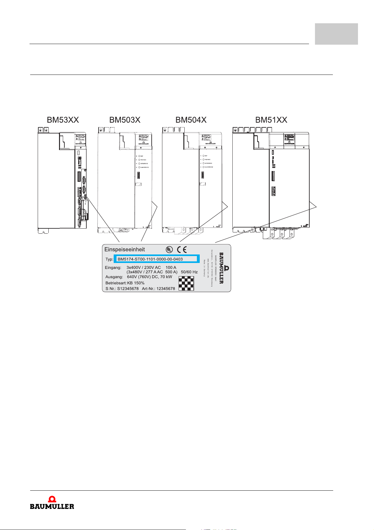
4.2.2 Type plate
Design and Operation
Examples of the locations where the type plate is affixed are shown in the figure.
Among other things, the type plate also sh
ows the type code of the device.
4
Figure 35: Affixing of the type plate
Instruction handbook b maXX 5000
Document No.: 5.09021.16
83
of 328

4.2
Identification of the device
4.2.3 Type code
The type code has the format: BM5XXX - XXXX - XXXX - XXXX - XX - XXXX.
The type code is explained in the following table.
BM5XXX-XXXX-XXXX-XXXX-XX-XXXX Device generation
BM5XXX-XXXX-XXXX-XXXX-XX-XXXX Device design
0: Mains rectifier
1: Active mains rectifier
3: Axis unit safety
5: Basic unit/power module safety
6: Basic unit/power module safety, optimized for peak current
7: Basic unit/power module safety, optimized for rated current, water-cooled
8: Multi-axis controller safety
BM5XXX-XXXX-XXXX-XXXX-XX-XXXX Housing size
1 to 9,
refer to ZDimensions– as from page 29.
BM5XXX-XXXX-XXXX-XXXX-XX-XXXX Current grading (output rated current)
2 to 8 (current value dependent on the housing size),
refer to ZElectrical data– as from page 58.
BM5XXX-XXXX-XXXX-XXXX-XX-XXXX Type of cooling
S: Air-cooled with air supply and with air outlet in the control cabinet
A: Air-cooled with air supply and with air outlet outside the control cabinet
Z: Water-cooled with water cooler in the control cabinet
F: Water-cooled with water cooler outside the control cabinet
C: Cold plate cooling via mounting wall of the control cabinet
BM5XXX-XXXX-XXXX-XXXX-XX-XXXX Type of power supply system
T: BM50XX, BM51XX: grounded TN or TT systems
I: BM50XX: IT systems, grounded TN or TT systems
G: BM50XX: Grounded delta systems, IT systems, grounded TN or TT systems
R: BM50XX with charge resistor: Grounded TN or TT systems
S: BM50XX with charge resistor: IT systems, grounded TN or TT systems
W: BM50XX with charge resistor: Grounded delta, IT systems,
grounded TN or TT systems
84
of 328
Instruction handbook b maXX 5000
Document No.: 5.09021.16 Baumüller Nürnberg GmbH

Design and Operation
BM5XXX-XXXX-XXXX-XXXX-XX-XXXX SAF modules (BM53XX only) / STO function (BM5030 only)
0: No SAF module / no STO function
1: BM5030 with STO function, basic type with feedback outputs
2: BM5030 with STO function, automatic locking function
refer to ZAppendix C - BM5030 with Safety Function– as from page 301
BM5-O-SAF
A: -000-000-001 SAF module standard without parameter memory
B: -000-000-000 SAF module with parameter memory
C: -001-000-000 STO controllable via I/O, with parameter memory,
without automatic restart
D: -001-000-002 STO controllable via I/O, with parameter memory,
with automatic restart
E: -002-000-000 STO controllable via I/O and FSoE, with parameter
memory, with daisy-chain inputs, without separated grounds,
with 12h encoder test
F: -002-001-000 STO controllable via I/O and FSoE, with parameter
memory, without daisy-chain inputs,
without separated grounds, with 12h encoder test
G: -003-000-000 STO controllable via I/O and FSoE, with parameter
memory, with daisy-chain inputs, without separated grounds,
with 12h encoder test
H: -003-001-000 STO controllable via I/O and FSoE, with parameter
memory, without daisy-chain inputs,
without separated grounds, with 12h encoder test
I: -001-001-000 STO controllable via I/O, without parameter memory,
with automatic restart, with short-circuit test
K: -001-001-001 SS1 controllable via I/O (SS1 time is a fixed set value),
without parameter memory, with automatic restart,
with short-circuit test
4
BM5XXX-XXXX-XXXX-XXXX-XX-XXXX Power unit design
BM50XX, BM51XX
0: X1 inhibit input expects NO contact, refer to ZFigure 64– on page 143
1: X1 inhibit input expects NC contact, refer to ZFigure 65– on page 144,
error reset via power supply off power supply on, refer to ZPage 238–
BM532X
2: With motor brake, instruction handbook 5.09021.03 is valid
3: Without motor brake, instruction handbook 5.09021.03 is valid
4: With motor brake, 3-pole motor connector, PE screw terminals
5: Without motor brake, 3-pole motor connector, PE screw terminals
BM533X to BM537X
2: With motor brake
3: Without motor brake
BM5XXX-XXXX-XXXX-XXXX-XX-XXXX Encoder evaluation
00: None
01: Encoder 1 and Encoder 2:
HIPERFACE®, EnDat® 2.1, SSI, square and sine incremental encoder, resolver
02: Encoder 1 and Encoder 2: EnDat® 2.2
03: Encoder 1 and Encoder 2: HIPERFCACE DSL
06: Encoder 1: refer to 01, Encoder 2: EnDat® 2.2
07: Encoder 1: refer to 01, Encoder 2: HIPERFCACE DSL
08: Encoder 1: EnDat® 2.2, Encoder 2: refer to 01
®
®
Instruction handbook b maXX 5000
Document No.: 5.09021.16
85
of 328

4.2
Identification of the device
BM5XXX-XXXX-XXXX-XXXX-XX-XXXX Add-on module
00: Without module
01: With option module IEE with external supply
03: With option module SIE with internal supply
04: With option module SVP-001-001, 4 analog inputs (for voltage),
4 analog outputs (voltage)
05: With option module SVP-001-002, 4 analog inputs (2 for voltage,
2 for current), 4 analog outputs (voltage)
06: With option module SVP-001-003, 4 analog inputs (for current)
4 analog outputs (voltage)
07: With option module EIP-001-001 EthernetIP incl. IEE with external supply
08: With option module MOD-001-001 Modbus/TCP incl. IEE with external supply
BM5XXX-XXXX-XXXX-XXXX-XX-XXXX Fieldbus configuration
01: EtherCAT® CoE
02: VARAN
03: CANopen
04: POWERLINK
05: ProfiNET RT/IRT
07: EtherCAT
®
®
®
SoE
BM5XXX-XXXX-XXXX-XXXX-XX-XXXX Hardware configuration controller
See ZPage 87–.
BM5XXX-XXXX-XXXX-XXXX-XX-XXXX Version
00: Standard
01: PCB with protective lacquer
02: Special version for customer
03: PCB with protective lacquer, without accesso
04: Without accessories kit, without DC link rails
05: Special version for customer
BM5XXX-XXXX-XXXX-XXXX-XX-XXXX Controller software version
NOTE!
Only devices with type code BM5XXX-XXXX-X
X01/03 and -XX04/05/06 provide an
add-on module!
The add-on modules are built-in and cannot be changed.
It is forbidden to remove the yellow front cover.
ries kit, without DC link rails
86
of 328
Instruction handbook b maXX 5000
Document No.: 5.09021.16 Baumüller Nürnberg GmbH

Design and Operation
4
Hardware configuration controller
BM5XXX - XXXX - XXXX - XXXX - XX - XXXX - EXX
01: BSCsafe Step 1 V.1 (for single and double axis),
with AIO, DIO, encoder, EtherCAT® (RJ45)
02: BSCsafe Step 1 V.2 (for single axis),
with AIO, DIO, encoder, EtherCAT® (RJ45)
04: BSCsafe Step 1 V.4 (for active mains converter),
without AIO, without encoder evaluation, without add-on module
05: Reserved
06: BSCsafe Step 1 V.1 (for single and double axis),
with AIO, DIO, encoder, EtherCAT® (RJ45), with additional +24 V supply for DIO and motor brake
07: BSCsafe Step 1 V.4 (for active mains converter),
without AIO, without encoder evaluation, without add-on module, with additional +24 V supply for DIO
08: BSCsafe Step 2 (for BM53XX, BM55XX, BM56XX, BM57XX), with AIO, DIO, encoder, fieldbus (RJ45)
09: BSCsafe Step 2 (for BM53XX, BM55XX, BM56XX, BM57XX),
with AIO, encoder, fieldbus (RJ45), without DIO
10: BSCsafe Step 2 (for BM53XX, BM55XX, BM56XX, BM57XX)
with AIO, DIO, encoder, fieldbus (RJ45), both pulse enables are switched-on permanently
28: BSCsafe Step 2 (for BM53XX, BM55XX, BM56XX, BM57XX),
with AIO, DIO, encoder, fieldbus (RJ45), 450 MHz
29: BSCsafe Step 2 (for BM53XX, BM55XX, BM56XX, BM57XX),
with AIO, encoder, fieldbus (RJ45), without DIO, 450 MHz
30: BSCsafe Step 2 (for BM53XX, BM55XX, BM56XX, BM57XX),
with AIO, DIO, encoder, fieldbus (RJ45), 450 MHz, both pulse enables are switched-on permanently
31: Reserved
58: BSCsafe Step 2 (for BM53XX, BM55XX, BM56XX, BM57XX), with AIO, DIO, encoder, fieldbus (M8)
59: BSCsafe Step 2 (for BM53XX, BM55XX, BM56XX, BM57XX),
with AIO, encoder, fieldbus (M8), without DIO
60: BSCsafe Step 2 (for BM53XX, BM55XX, BM56XX, BM57XX),
with AIO, DIO, encoder, fieldbus (M8), both pulse enables are switched-on permanently
61: BSCsafe Step 2 (for BM53XX, BM55XX, BM56XX, BM57XX),
with fieldbus (M8), DIO (but 4 normal digital inputs only, 2 of them for pulse enable),
without AIO, without 2nd encoder
62: BSCsafe Step 2 (for BM53XX, BM55XX, BM56XX, BM57XX),
with fieldbus (M8), without AIO, without DIO, without 2nd encoder
80: BSCsafe Step 2 (for BM53XX, BM55XX, BM56XX, BM57XX),
with AIO, DIO, encoder, fieldbus (M8), 450 MHz, both pulse enables are switched-on permanently
81: BSCsafe Step 2 (for BM53XX, BM55XX, BM56XX, BM57XX),
with fieldbus (M8), DIO (DIO (but 4 normal digital inputs only, 2 of them for pulse enable), 450 MHz,
without AIO, without 2nd encoder
82: BSCsafe Step 2 (for BM53XX, BM55XX, BM56XX, BM57XX),
with fieldbus (M8), 450 MHz, without AIO, without DIO, without 2nd encoder
Software option SoftDrivePLC
BM5XXX - XXXX - XXXX - XXXX - XX - XXXX - EXX,
and XX > 01
Safety Level
BM5XXX - XXXX - XXXX - XXXX - XX - XXXX - [EXX] - #XX
Mounting position of b maXX 5000
BM5XXX - XXXX - XXXX - XXXX - XX - XXXX - [EXX] - #XX - [M0],
M0: Mounting position turned by 180°
Instruction handbook b maXX 5000
Document No.: 5.09021.16
87
of 328

4.3
UL notes
4.3 UL notes
The notes below must be observed in case you consider UL 508 C.
quired environmental conditions– on page 47
ZRe
n Note the maximum s
n Use in a pollution
ZDe
sign– on page 81
n Axis units (BM5X23
BM5X35)are allowed to be used only in combination with mains rectifiers
(BM5031, BM5032, BM5043, BM5044, BM5174).
stallation procedure– on page 141
ZIn
n Internal overload protecti
load.
ZElectr
ical connections– as from page 157
n Position of
supply, load, control circuit, and similar devices refer to ZPage
wiring terminals to indicate the proper connections for the power
urrounding air temperature.
degree 2 environment only.
, BM5X26, BM5X27, BM5X28, BM5X31, BM5X32, BM5X33, BM5X34,
on operates after exceeding 200 % of the motor full
157–.
Connections of ZPa
n Note tightening to
ZRe
quirements for the connection cables– on page 128
n Use 60°/75°copper
ZRe
quirements for the motor temperature sensors– on page 140
n Drives do not prov
88
of 328
ge 166– to ZPage 167–
rque values marked for field terminals.
wires only.
ide motor overtemperature sensing.
Instruction handbook b maXX 5000
Document No.: 5.09021.16 Baumüller Nürnberg GmbH

ZFuses– as from page 261
Design and Operation
4
n Devices are suit
50000 rms symmetrical amperes, 480 Volt maximum, when protected by J Class
fuses rated
n BM5031/B
branch circuit protection fuse rating: 600 V / max. 60 A
n BM5043/B
branch circuit protection fuse rating: 600 V / max. 150 A
n Fuses mu
BM51XX)
n Integral so
protection. Branch circuit protection must be provided in accordance with the
Manufacturer Instructions, National Electrical Code and any additional local
codes.
ZElectrical data BM50X
n Mains rect
loading. Total capacity of all axis units BM53XX connected to the mains rectifier shall not exceed the rectifiers rating.
M5032:
M5044/BM5174
st be installed on the line side of the mains rectifier (BM50XX,
lid state short circuit protection does not provide branch circuit
ifiers BM50XX, BM51XX are not provided with DC link preventing over-
able for use on a circuit capable of delivering not more than
X; BM51XX– as from page 58
unting of the DC link bar– as from page 116 and ZDC link bar– on page 287
ZMo
n Proper installa
page 116 and prop
tion of the DC link bar, refer to ZMounting of the DC link bar– as from
er DC link bar refer to ZDC link bar– on page 287.
Instruction handbook b maXX 5000
Document No.: 5.09021.16
89
of 328

4.4
Display and operating elements
4.4 Display and operating elements
NOTE!
Description of BM5030 with safety function BM5030-XX2X-...
refer to ZC.4
4.4.1 LED display BM5XXX-XX0X-... without safety function
LED display BM5030 with safety function– as from page 306.
LED
H1
LED
H2
LED
H3
LED
H4
Figure 36: Display/operating elements BM50XX without safety function
Mains rectifier unit ready-to-operate
green:
red:
blinking red: Pow
Phase failure
red:
red:
Over temperature
red:
DC link error:
U
DC link
U
DC link
Inhibit input active
Power supply and DC link voltage available,
internally OK
Power supply failure - automatically restart
when power supply returns.
er supply failure longer than 10 s - restart
after Power supply return has to be acknowledged (X1:4).
Refer to ZEr
on page 238.
overvoltage or
overcurrent or
ror acknowledgment of BM50XX–
90
of 328
Instruction handbook b maXX 5000
Document No.: 5.09021.16 Baumüller Nürnberg GmbH

Design and Operation
4
Naming on the
front plate
H1 (green) Ready-to-operate no error LED lights up
H1 (red) Mains failure power supply failure - automatically restart
H2 (red) Phase failure warning: phase failure or asymmetric three
H3 (red) Over temperature over temperature of heat sink LED lights up
H4 (red) DC link error overvoltage DC link LED lights up
Meaning Error Blinking pattern
LED lights up
power supply returns.
when
power supply failure longer than 10 s - restart
after power
edged (X1:4).
ph
ase power supply
temperature of heat sink < - 5 °C LED lights up
overcurrent DC link LED lights up
rising edge (low-high) on inhibit input LED lights up
supply return has to be acknowl-
LED blinking
LED lights up
Instruction handbook b maXX 5000
Document No.: 5.09021.16
91
of 328

4.4
4.4.2 Display and operating elements BM51XX
Display and operating elements
X1 Service interface
H1 7 segment display
refer to Z7-
segment display BM51XX– on page 93
LED
H11 - H14
Address switch
S1 - S4
LED
H31
H32
H41
H42
Meaning: refer to ZLED dis
Setting: refer to ZSetting
switches– a
Fieldbus, depending on type
(refer to ZType code– as fr
Meaning:
BM51XX-XXXX-XXXX-00XX
no function
BM51XX-XXXX-XXXX-01XX
D EtherCAT® .– on page 98
ZLE
s from page 100.
play BM51XX– on page 94.
the IP address with address
om page 84)
92
of 328
BM51XX-XXXX-XXXX-02XX
D VARAN– on page 98
ZLE
BM51XX-XXXX-XXXX-04XX
D POWERLINK® .– on page 99
ZLE
Figure 37: Display/operating elements BM51XX
NOTE!
Only the service cable BM5-K-USB-XXX is allowed to be used for the service interface X1, refer to ZService interfac
page 250.
Instruction handbook b maXX 5000
Document No.: 5.09021.16 Baumüller Nürnberg GmbH
e– on page 205 and ZService interface cable– on

4.4.2.1 7-segment display BM51XX
Refer to parameter manual for detailed description of drive states and state transitions.
0: Low, 1: High
Design and Operation
4
Display
0
1
2
3
4
6
7
F
State
e manager
driv
NOT READY TO SWITCH ON Device message „Not ready for switching power on“
SWITCH-ON INHIBIT Device disabled
READY TO SWITCH ON Device shutdown
SWITCHED ON Control word: xxxx x111
OPERATION ENABLED Control word: xxxx 1111
OPERATION DISABLED Pulse enable = 0
QUICK DISCHARGE ACTIVE Quick discharge = 1 (high active)
ERROR Error message
Meaning
Control word: xxxx x110
Pulse enable = 0
Quick discharge = 0
Pulse enable = 1
Quick discharge = 0
Pulse enable = 1
Quick discharge = 0
Reset via control word 0xxx
or hardware input reset stored errors 0
xxxx
➝ 1
NOTE!
In addition the error No. is displayed, refer to ZBM51XX
tion– as
from page 237.
Instruction handbook b maXX 5000
Document No.: 5.09021.16
and BM53XX error detec-
93
of 328

4.4
4.4.2.2 LED display BM51XX
Display and operating elements
Naming on the
front plate
H11
H12
H13
H14
Internal identification Meaning
Power direction
1.1 green,
1.1 red
1.2 green,
1.2 red
1.3
1.4
H11 green: supply power
H11 red: regenerative braking
Power on / pulse enable 24 V available
H12 green: power ON
H12 red
Current limit
H13 red: device operates on current limit
Error display
H14 red: device error message
94
of 328
Instruction handbook b maXX 5000
Document No.: 5.09021.16 Baumüller Nürnberg GmbH

4.4.3 Display and operating elements BM53XX
X1 Service interface
Design and Operation
4
H1
H2
LED
H11 - H14
H21 - H24
Address switch
S1 - S4
LED
H31
H32
H41
H42
7 segment display axis 1
7 segment display axis 2 (double axis unit)
Display controller state
Meaning refer to: Z7-
LED axis 1
LED axis 2 (double axis unit)
Meaning: refer to ZLED dis
Setting: refer to ZSetting
switches– a
Fieldbus, depending on type
(refer to ZType cod
Meaning:
BM53XX-XXXX-XXXX-01XX
BM53XX-XXXX-XXXX-07XX
D EtherCAT® .– on page 98
ZLE
s from page 100.
segment display controller– on page 96
play controller– on page 97.
the IP address with address
e– as from page 84)
BM53XX-XXXX-XXXX-02XX
D VARAN– on page 98
ZLE
BM53XX-XXXX-XXXX-04XX
D POWERLINK® .– on page 99
ZLE
Figure 38: Display/operating elements controller BM53XX
NOTE!
Only the service cable BM5-K-USB-XXX is allowed to be used for the service interface X1, refer to ZServic
page 250.
e interface– on page 205 and ZService interface cable– on
Instruction handbook b maXX 5000
Document No.: 5.09021.16
95
of 328

4.4
4.4.3.1 7-segment display controller
Display and operating elements
Refer to parameter manual for detailed description of drive states and state transitions.
0: Low, 1: High
Display State
drive man
0
1
2
3
4
5
6
7
NOT READY TO SWITCH ON Drive message „Not ready for switching power on“
SWITCH-ON INHIBIT Inhibit voltage, e.g. quick stop active
READY TO SWITCH ON Drive shutdown
SWITCHED ON Control word: xxxx x111
OPERATION ENABLED Control word: xxxx 1111
BETRIEB SPERREN AKTIV
OPERATION INHIBIT ACTIVE Pulse enable = 0
QUICK STOP ACTIVE Quick stop = 0 (low active)
Meaning
ager
Control word: xxxx x110
Pulse enable = 0
Quick stop = 1 (low active)
Pulse enable = 1
Quick stop = 1
Pulse enable = 1
Quick stop = 1
E
F
P
ERROR RESPONSE ACTIVE
ERROR Error message
Reset via control word 0xxx xxxx
or reset stored errors 0
Parking axis
NOTE!
In addition the error No. is displayed, refer to ZBM5
tion– as
from page 237.
➝ 1
1XX and BM53XX error detec-
96
of 328
Instruction handbook b maXX 5000
Document No.: 5.09021.16 Baumüller Nürnberg GmbH

4.4.3.2 LED display controller
Design and Operation
4
Naming on the
front plate
H11 1.1 green,
H12 1.2 green,
H13 1.3 Axis 1: Current limit
H14 1.4 Axis 1: Error display
H21 2.1 green,
H22 2.2 green,
H23 2.3 Axis 2: Current limit
Internal identification Meaning
Axis 1: Torque direction
1.1 red
Axis 1: Power on / pulse enable 24 V available
1.2 red
Axis 2: Torque direction
2.1 red
Axis 2: Power on / pulse enable 24 V available
2.2 red
H11 green: Positive torque direction
H11 red: Negative torque direction
H12 green: Power ON
H12 red:
H13 red: Device operates on current limit
H14 red: Device error message
H21 green: Positive torque direction
H21 red: Negative torque direction
H22 green: Power ON
H22 red:
H23 red: Device operates on current limit
H24 2.4 Axis 2: Error display
H24 red: Device error message
Instruction handbook b maXX 5000
Document No.: 5.09021.16
97
of 328

4.4
4.4.4 LED display fieldbus
LED EtherCAT® . Type code
Display and operating elements
BM5XXX-XXXX-XXXX-01XX
BM5XXX-XXXX-XXXX-07XX
Naming on the
front plate
H31 (green) X3 Link / Act Off: No connection
H32 (yellow) ERROR On: ERROR (receiver error Phy1/Phy2)
H41 (green) X4 Link / Act Off: No connection
H42 (yellow) RUN Off: ERROR/INIT
Meaning Blinking pattern
On: Connection
Blinking: Data transfer
On: Connection
Blinking: Data transfer
500 ms on /
500 ms off: PREOPERATIONAL
200 ms on /
1 s off: SAFEOPERATIONAL
On: OPERATIONAL
LED VARAN Type code
BM5XXX-XXXX-XXXX-02XX
Naming on the
front plate
H31 (green)
H41 (green)
H32 (yellow)
H42 (yellow)
LED CANopen
98
of 328
®
Instruction handbook b maXX 5000
Document No.: 5.09021.16 Baumüller Nürnberg GmbH
Meaning Blinking pattern
LINK On: Connection between 2 PHYs
ACTIVE On: Data is received or transmitted
Type code
BM5XXX-XXXX-XXXX-03XX
No function
(physical interfaces) is established

Design and Operation
4
LED
POWERLINK
Naming on the
front plate
H31 (green) X3 Link / Act Off: No connection
H32 (yellow) ERROR Off: NMT_CT3, NMT_CT7, NMT_GT2
H41 (green) X4 Link / Act Off: No connection
H42 (green) STATUS Off: NMT_GS_OFF, NMT_GS_INITIALISATION,
®
Type code
.
BM5XXX-XXXX-XXXX-04XX
Meaning Blinking pattern
On: Connection
Blinking: Data transfer
On: NMT_CT11, NMT_GT6
Blinking: Configuration error (e.g. address seting)
On: Connection
Blinking: Data transfer
NMT_CS_NOT_ACTIVE
50 ms off /
50 ms on: NMT_CS_BASIC_ETHERNET
200 ms on /
1 s off: NMT_CS_PRE_OPERATIONAL_1
2 x 200 ms on /
1 s off: NMT_CS_PRE_OPERATIONAL_2
3 x 200 ms on /
1 s off: NMT_CS_READY_TO_OPERATE
On: NMT_CS_OPERATIONAL
200 ms on /
200 ms off: NMT_CS_STOPPED
Instruction handbook b maXX 5000
Document No.: 5.09021.16
99
of 328

4.4
EtherCAT® or VARAN profile:
POWERLINK® profile
Switch setting up
Switch setting down
Switch setting up
Switch setting down
Display and operating elements
4.4.5 Setting the IP address with address switches
EtherCAT® CoE
EtherCAT
®
SoE
BM5XXX-XXXX-XXXX-01XX
BM5XXX-XXXX-XXXX-07XX
VARAN BM5XXX-XXXX-XXXX-02XX
POWERLINK
IP-Address
S1 to S4
®
BM5XXX-XXXX-XXXX-04XX
The IP address of the controller consists of 32
®
Controller with EtherCAT
or VARAN profile: Both of the first bytes are set with the base
address (192.168.) at the factory. Both of the last bytes are set by means of the address
switches S1, S2, S3 and S4. In the process, S1 and S2 as well as S3 and S4 each represent an 8 bit value.
Controller with POWERLINK
(192.168.100) at the factory. The last byte is set by means of the address switches S3
and S4. In the process, S3 and S4 each represent an 8 bit value.
The IP address 192.168.0.0 or 192.168.100.0 is not permitted/reserved.
For information on changing the base address, refer to the parameter manual.
bits or 4 bytes (e.g. 192.168.125.203).
®
-profile: The first three bytes are set with the base address
100
of 328
Instruction handbook b maXX 5000
Document No.: 5.09021.16 Baumüller Nürnberg GmbH
 Loading...