

Page 1

Manual
Programming Software ProCam 1.10
for Absolute Switching Cam Encoders
Baumer IVO GmbH & Co. KG
Dauchinger Strasse 58-62
DE-78056 Villingen-Schwenningen
Phone +49 (0)7720 942-0
Fax +49 (0)7720 942-900 05.11 · 174.02.034/3
info.de@baumerivo.com Subject to modification in technic and design.
www.baumer.com Errors and omissions excepted.
Page 2

Content
Introduction 4
1
1.1 Product assignment 4
2 General Information 5
2.1 System requirements 5
2.2 Installation 5
2.3 Software version 5
2.4 Information on commissioning 5
3 ProCam Program 6
3.1 Basics 6
3.2 Program procedure 6
3.2.1 Selecting encoder type 7
3.2.2 Encoder connected to PC - "Automatic selection" 8
3.2.3 Selecting encoder type from table - "Manual selection" 9
3.2.4 Starting encoder programming 10
4 Program Encoder 11
4.1 Menu and icon bar 12
4.1.1 File 12
4.1.2 Settings 13
4.1.3 Extras 14
4.1.4 Info 15
4.1.5 Reprogramming 15
4.1.6 Open file 15
4.1.7 Save file 15
4.1.8 Print 15
4.1.9 Request data from encoder 15
4.1.10 Send data to encoder (save) 15
4.1.11 Display position/activate cam program 15
4.2 "Resolution" programming mask 16
4.2.1 Code (steps) 17
4.2.2 Counting direction 17
4.2.3 Speed scaling 17
4.2.4 Revolutions 18
4.2.5 Steps/revolutions 18
4.2.6 Total resolution 18
4.2.7 Back to main menu 18
4.2.8 Dialog window 18
4.2.9 Display of encoder type 18
4.2.10 Read encoder data 19
4.2.11 Send encoder data 19
4.3 "Outputs" programming mask 20
4.3.1 Output 21
4.3.2 Data Valid 21
4.3.3 Speed 21
4.3.4 Still 21
4.3.5 Run Control 21
4.3.6 Inverted 21
Manual_ProCam_V1-10_EN.doc 2/35 Baumer IVO GmbH & Co. KG
10.05.11 Villingen-Schwenningen, Germany
Page 3

4.3.7 Speed monitoring 21
4.4 "Program encoder" programming mask 22
4.4.1 Edit cam program 23
4.4.2 Send cam program 25
4.4.3 Activate cam program 25
4.4.4 Dialog window 25
4.4.5 Program status 25
4.5 "Cam" programming mask 26
4.5.1 Program 26
4.5.2 Cam memory 27
4.5.3 Cam No. 27
4.5.4 Output 27
4.5.5 Name 27
4.5.6 ON/OFF 27
4.5.7 DTC ON/DTC OFF 27
4.5.8 Lock 27
4.5.9 Status 28
4.5.10 Name outputs 28
4.5.11 Enter DTC values 29
4.5.12 Lock outputs 29
4.6 "Display position" and "Activate cam program" mask 30
4.7 "Set position" mask 32
5 Connecting Encoder 34
5.1 Connection between PC and encoder 34
5.1.1 Encoder programming connection 34
6 Index 35
Manual_ProCam_V1-10_EN.doc 3/35 Baumer IVO GmbH & Co. KG
10.05.11 Villingen-Schwenningen, Germany
Page 4

1 Introduction
1.1 Product assignment
This ProCam software is suitable for the following types:
Hollow shaft encoders
Product Product Family interface
RXA1H Cam-operated switchgroup RS232 or RS485
Manual_ProCam_V1-10_EN.doc 4/35 Baumer IVO GmbH & Co. KG
10.05.11 Villingen-Schwenningen, Germany
Page 5

2 General Information
2.1 System requirements
A PC with the operating system Windows 95/98/NT/2000/XP with one free RS232 serial port.
An RS485/RS232 interface converter with automatic directional switchover is required for
encoders with an RS485 interface.
2.2 Installation
The installation is menu-guided.
Please read the file "Readme.txt" on the included CD.
Note: Under Windows NT/2000 and Windows XP, the installation can only be carried out with
Administrator rights.
2.3 Software version
The version ProCam 1.10 replaces the earlier ProCam versions and is downward compatible.
2.4 Information on commissioning
- Wiring work on the encoder plug or in the switch cabinet may only be carried
out in the deenergized state. Do not connect or disconnect encoder plugs
while energized.
- Before switching on, please check and connect all connectors.
- Caution!
Incorrect encoder programming can lead to system failure.
Product information
The content or scope of this documentation can be changed at any time without prior notice.
The contents of this documentation does not represent the assurance of a certain property or
function by Baumer IVO GmbH & Co. KG.
Manual_ProCam_V1-10_EN.doc 5/35 Baumer IVO GmbH & Co. KG
10.05.11 Villingen-Schwenningen, Germany
Page 6
3 ProCam Program
3.1 Basics
The ProCam program is a software for programming Baumer IVO cam encoders. It can be
used to read out, change, program and display the encoder data. To make programming as
simple as possible, the user can select only the fields valid for the respective state. Fields
which cannot be selected in the current state have a gray background. Before the encoder can
be programmed, the encoder type must be selected. This results in a logical procedure
following the program start:
1. Step Select language with country flags
2. Step Select encoder type with "Select encoder" button
3. Step Programming can be started
If your encoder is not automatically detected, or is not contained in the selection list, please
contact Baumer IVO.
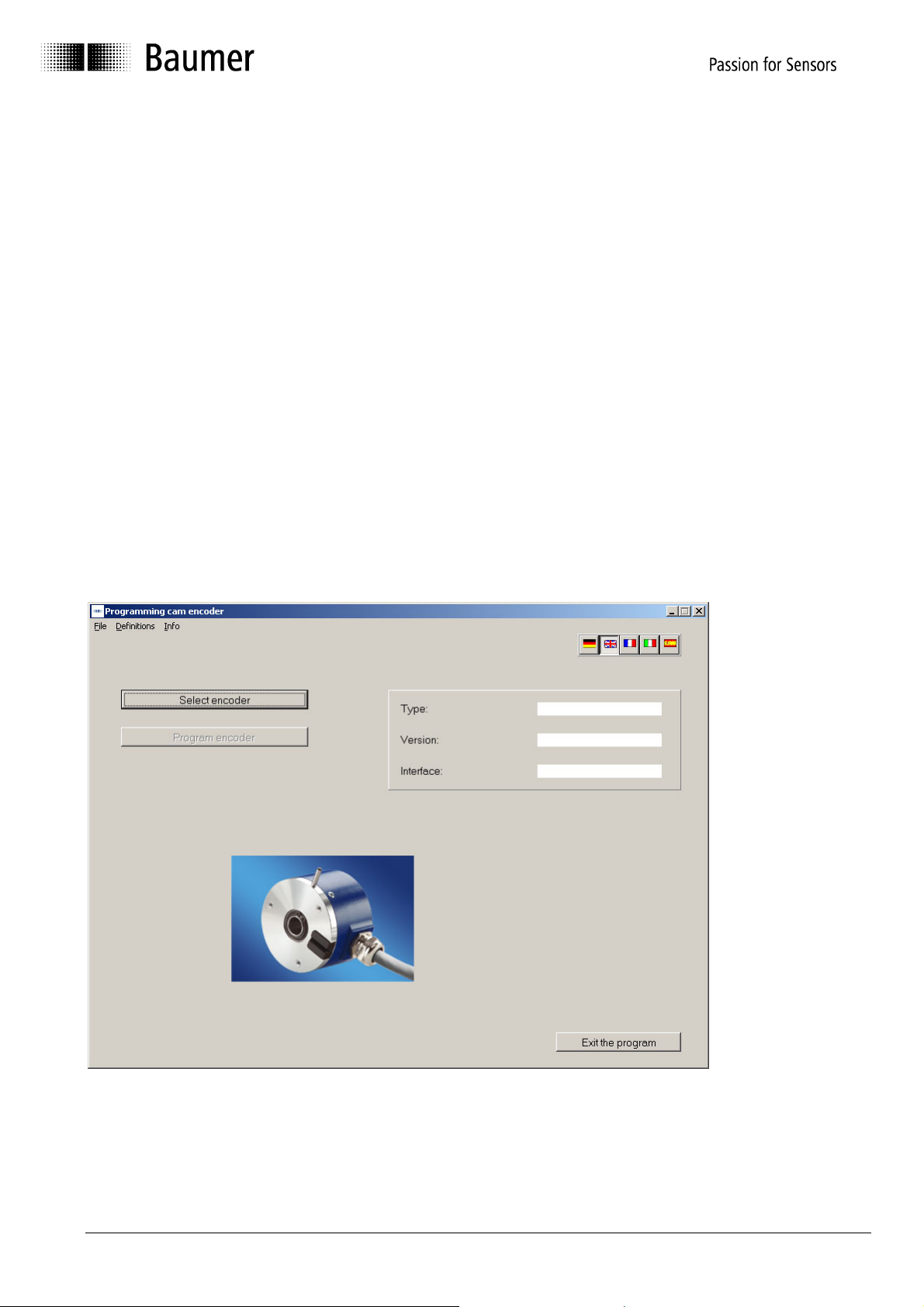
3.2 Program procedure
After the Start screen has run, the following mask appears:
Programming cannot begin until an encoder type has been selected.
Encoder selection is described in the chapters "Encoder connected to PC ⇒ Automatic
selection" and "Select encoder type from table ⇒ Manual selection".
Manual_ProCam_V1-10_EN.doc 6/35 Baumer IVO GmbH & Co. KG
10.05.11 Villingen-Schwenningen, Germany
Page 7
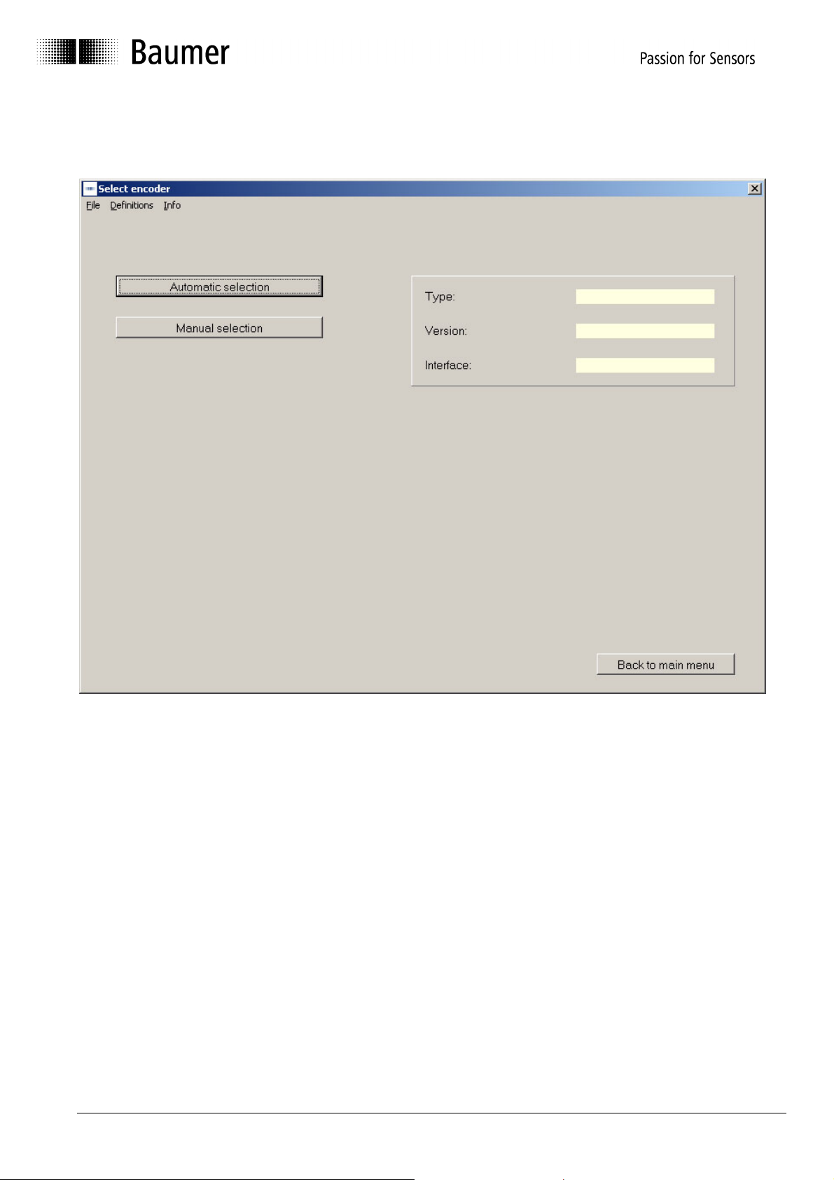
3.2.1 Selecting encoder type
The encoder can be selected in the first step.
The program offers automatic selection when an encoder is connected to the interface.
If there is no connection to the encoder, a desired encoder type can be selected from the list
with "Manual selection".
Manual_ProCam_V1-10_EN.doc 7/35 Baumer IVO GmbH & Co. KG
10.05.11 Villingen-Schwenningen, Germany
Page 8
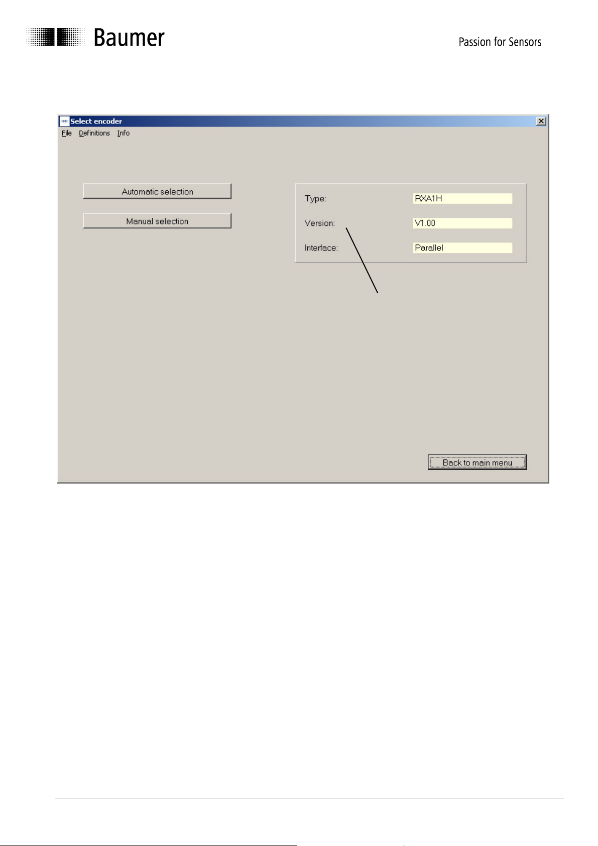
3.2.2 Encoder connected to PC - "Automatic selection"
A
utomatically
detected
encoder model
With an encoder selected, the encoder type can be read out (Automatic selection).
This information is necessary to provide the corresponding parameters for
programming. If the encoder or the cable connection is not properly connected, an
error message is displayed. If the automatically detected encoder does not match the
encoder rating plate, please contact Baumer IVO.
Manual_ProCam_V1-10_EN.doc 8/35 Baumer IVO GmbH & Co. KG
10.05.11 Villingen-Schwenningen, Germany
Page 9
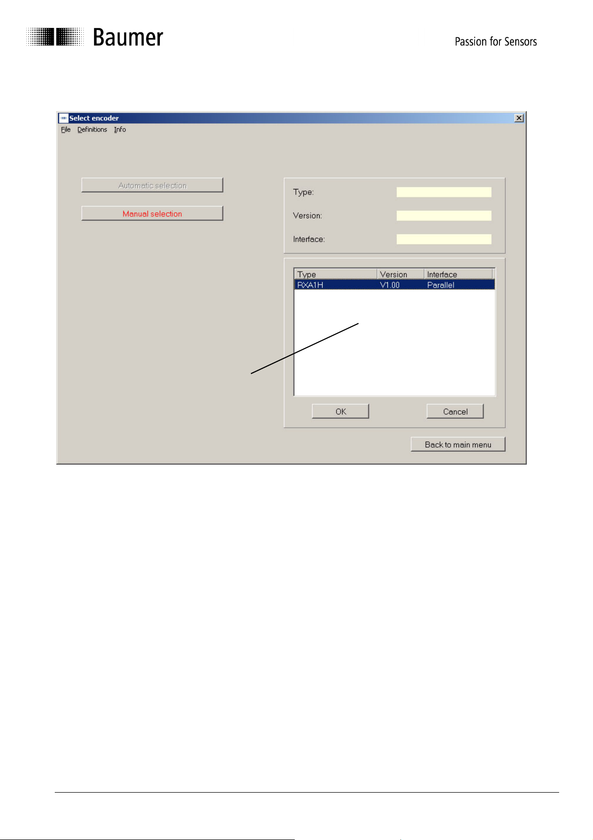
3.2.3 Selecting encoder type from table - "Manual selection"
Table for
selecting
encoder model
If no encoder is connected to the PC, the encoder type can be selected from the table
(Manual selection). The most common types are contained in the table. Not only the type,
but also the version is important. If your type is not included, please contact Baumer IVO.
The type and version can be read off the encoder rating plate.
Manual_ProCam_V1-10_EN.doc 9/35 Baumer IVO GmbH & Co. KG
10.05.11 Villingen-Schwenningen, Germany
Page 10
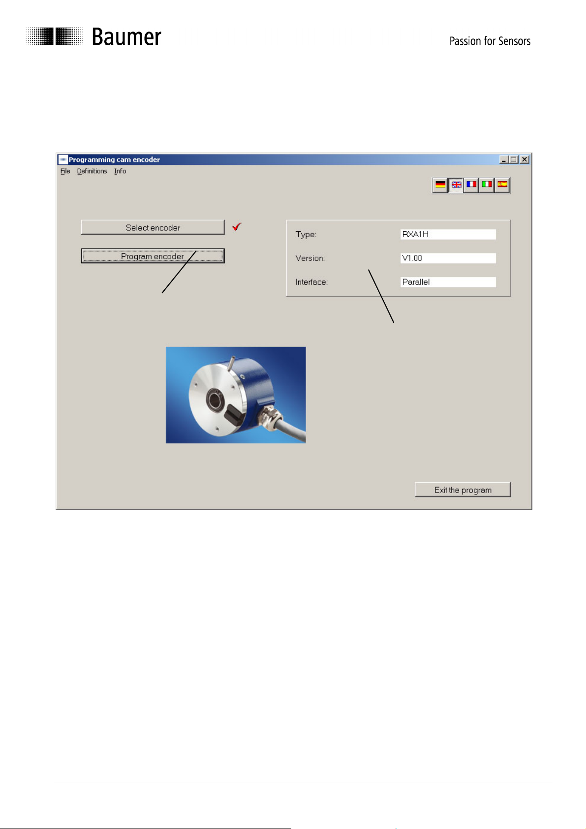
3.2.4 Starting encoder programming
After successfully selecting the encoder, programming can be started. The "Program
encoder" button is now active. The selected encoder is shown again in the right-hand
mask.
Encoder
programming
is active
Selected
encoder
Manual_ProCam_V1-10_EN.doc 10/35 Baumer IVO GmbH & Co. KG
10.05.11 Villingen-Schwenningen, Germany
Page 11
4 Program Encoder
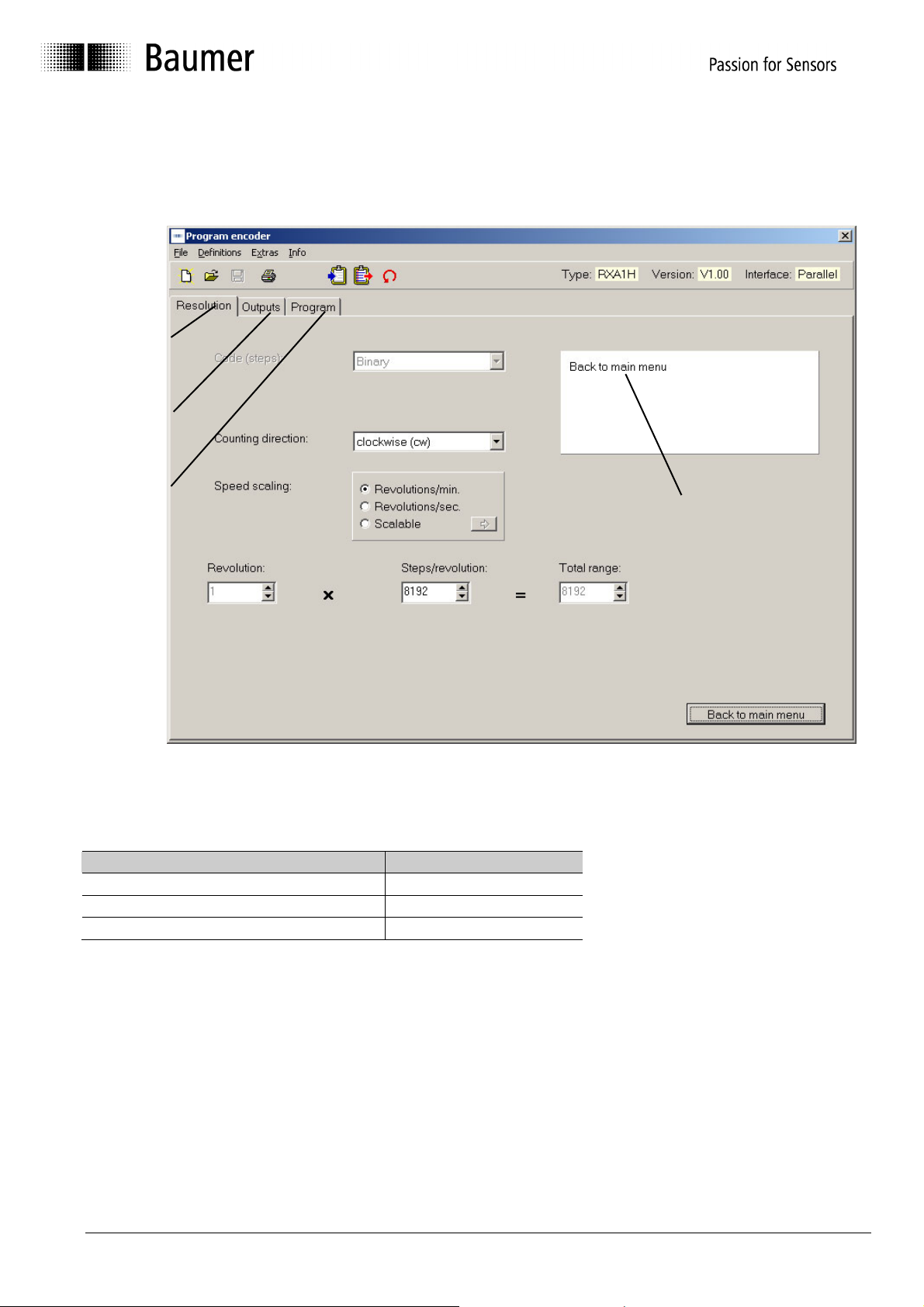
The "Program encoder" mask now enables the programming of all parameters possible for this
encoder.
Resolution
tab
Outputs
tab
Program
Dialog window
tab
The parameters for the encoder can be set with the tabs "Resolution", "Outputs" and
"Program". The dialog window offers additional support and explanations for the selected
window.
Tab Explanations
"Resolution" tab See Chapter 4.2
"Outputs" tab See Chapter 4.3
"Program" tab See Chapter 4.4
Manual_ProCam_V1-10_EN.doc 11/35 Baumer IVO GmbH & Co. KG
10.05.11 Villingen-Schwenningen, Germany
Page 12
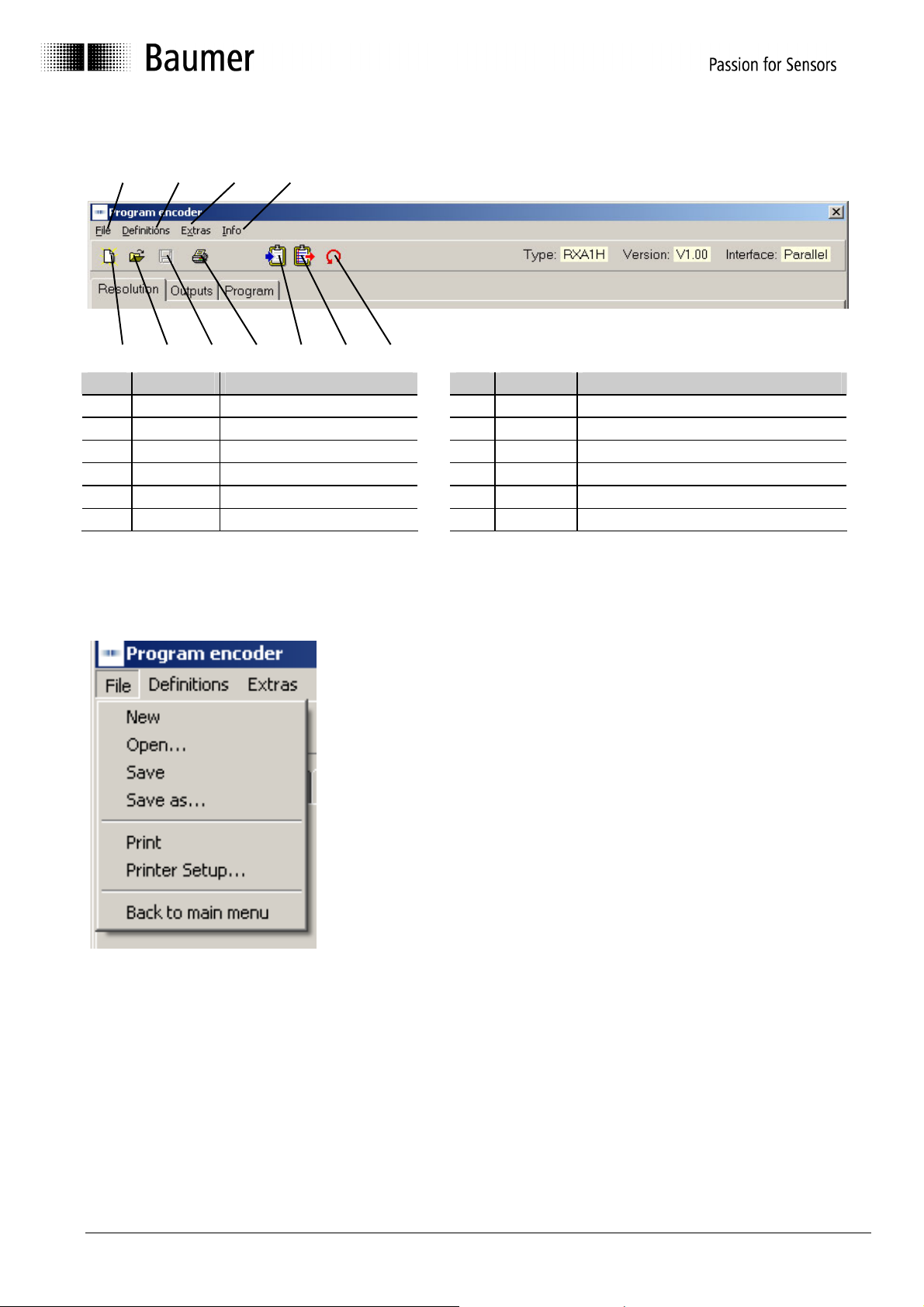
4.1 Menu and icon bar
1
5
No. Chapter Buttons No. Chapter Buttons
1 4.1.1 File 7 4.1.7 Save file
2 4.1.2 Definitions 8 4.1.8 Print
3 4.1.3 Extras 9 4.1.9 Load data from encoder
4 4.1.4 Info 10 4.1.10 Save data in encoder
5 4.1.5 Reprogramming 11 4.1.11 Display position
6 4.1.6 Open file
2 3 4
6 7 8 9 10 11
4.1.1 File
In the "File" menu item the following items can be selected:
New: A programming mask with the
Open: A saved program can be loaded.
Save: The current data can be saved.
Save as: The current data can be saved
freely selectable directory.
Print: The current data can be printed for
Printer setup: A printer can be selected.
Back to main menu: The programming mask is exited.
basic setting is loaded.
under any desired name in a
archiving.
Manual_ProCam_V1-10_EN.doc 12/35 Baumer IVO GmbH & Co. KG
10.05.11 Villingen-Schwenningen, Germany
Page 13

4.1.2 Settings
In the "Settings" menu item the COM 1 to COM 6 serial port
to which the encoder is connected can be selected. In
addition, the baud rate and the address of the encoder can be
set. The other parameters such as Parity, Stop bits and Data
bits can be checked here.
The port parameters are permanently set for the RXA1H series.
- Baud rate: 38400
- Parity: Even
- Stop bits: 1
- Data bits: 8
Manual_ProCam_V1-10_EN.doc 13/35 Baumer IVO GmbH & Co. KG
10.05.11 Villingen-Schwenningen, Germany
Page 14
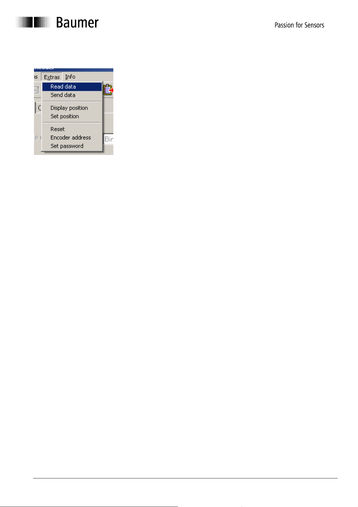
4.1.3 Extras
Read data: The data are requested from the connected encoder
Send data: The current programming is saved in the encoder
Display position: The "Display position" screen mask is opened (see Chapter 4.6)
Set position: The mask for assigning a position value is opened (see Chapter 4.7)
Reset: The encoder receives a reset command. The effect is identical to
switching the supply voltage off and then on again. No cam programs or
stored settings are deleted or changed.
Encoder address: The address set for the connected encoder can be requested or set.
Set password: A four-place password can be saved in the encoder. ProCam requests
the password during certain actions and compares it with the password
stored in the encoder. Among other things, this concerns the "locked
outputs" and prevents accidental changes. The default password on
delivery is "0000". Permissible characters are 0 - 9 and A - Z, as well as
blank spaces. It must especially be noted that a password can only be
deleted or changed when the password used up until that point is known.
Manual_ProCam_V1-10_EN.doc 14/35 Baumer IVO GmbH & Co. KG
10.05.11 Villingen-Schwenningen, Germany
Page 15

4.1.4 Info
With Info the version of the ProCam and encoder software can be displayed.
4.1.5 Reprogramming
The display mask is reset to the basic setting. The same function can also be run
with "File ⇒ New".
4.1.6 Open file
Programming stored in the PC can be loaded. The same function can also be run
with "File ⇒ Open".
4.1.7 Save file
The current data are saved in the PC. The same function can also be run with "File
⇒ Save".
4.1.8 Print
The current encoder data are printed out. The printout can be used for archiving.
The same function can also be run with "File ⇒ Print".
4.1.9 Request data from encoder
The data are requested from the connected encoder. The same function can also be
run with "Extras ⇒ Read data".
4.1.10 Send data to encoder (save)
The current programming is saved in the encoder. The same function can also be
run with "Extras ⇒ Send data".
4.1.11 Display position/activate cam program
The current position and the status of the special outputs are shown. The same
function can also be run with "Extras ⇒ Display position".
Manual_ProCam_V1-10_EN.doc 15/35 Baumer IVO GmbH & Co. KG
10.05.11 Villingen-Schwenningen, Germany
Page 16

4.2 "Resolution" programming mask
The resolution and other basic parameters of the encoder can be set with this programming
mask. The picture below shows the maximum possible settings. However, only those
parameters are shown which are supported by the selected encoder.
12
11 10
1
9
2
8
3
654
7
No. Chapter Field No. Chapter Field
1 4.2.1 Code (steps) 7 4.2.7 Back to main menu
2 4.2.2 Counting direction 8 4.2.8 Dialog window
3 4.2.3 Speed scaling 9 4.2.9 Display of encoder type
4 4.2.4 Revolutions 10 4.2.10 Read encoder data
5 4.2.5 Steps/revolution 11 4.2.11 Send encoder data
6 4.2.6 Total range 12 4.5 Display position
Manual_ProCam_V1-10_EN.doc 16/35 Baumer IVO GmbH & Co. KG
10.05.11 Villingen-Schwenningen, Germany
Page 17

4.2.1 Code (steps)
The code (steps) is permanently set to binary.
4.2.2 Counting direction
With the counting direction it is possible to choose between "increasing clockwise"and
"decreasing clockwise". "Increasing clockwise" means that with clockwise rotation (looking
from the front at the encoder shaft), the position values increase, and with "decreasing
clockwise" these decrease accordingly.
4.2.3 Speed scaling
You can select from three settable functions (Revolutions/min, Revolutions/s or Scaleable) for
the display of the speed in the "Display position" window (Chapter 4.6).
Revolutions/min.
The display is shown in revolutions per minute.
Revolutions/sec.
The display is shown in revolutions per second.
Scaleable
Enter the value in the range from 1 - 6,5000 here which is to be
displayed at a speed of 6,000 revolutions/minute in the
"Display position" window (see Chapter 4.6).
Example:
The cam encoder is attached to a downstream gear unit that
reduces the motor speed in a ratio of 1:3. However, the motor
speed (in rpm) is to be displayed. Enter the value 18,000 in the
"Speed scaling" window. For an encoder shaft speed of 2,000
rpm, the display is now "6000".
Manual_ProCam_V1-10_EN.doc 17/35 Baumer IVO GmbH & Co. KG
10.05.11 Villingen-Schwenningen, Germany
Page 18

4.2.4 Revolutions
With singleturn encoders, the value for the rotations cannot be set. It is always set to 1.
4.2.5 Steps/revolutions
Number of steps with which a rotation of the encoder axis is to be resolved. The possible value
range lies between 2 and 8192 steps/rotation.
4.2.6 Total resolution
The total resolution is the product of steps/rotation multiplied by the number of rotations.
Calculation formula for the total resolution:
1. Singleturn encoder
1 X Steps/revolutions = Total Resolution
2. Multiturn encoder
Revolutions X Steps/revolutions = Total Resolution
e.g. For 100 steps/rotation and a desired number of rotations of 10
the total resolution is 1000.
Depending on the encoder type, either the number of rotations or the total resolution can be
set. The other value is highlighted in gray, and can therefore not be changed. However, the
value is calculated and displayed.
Information:
This revolution can also be used for movements which run through the zero point several
times in the same direction (endless operation).
4.2.7 Back to main menu
The "Return to main menu" button exits the programming mask. If parameters have been
changed, these can still be saved.
4.2.8 Dialog window
Information texts on the parameter currently selected are shown in the dialog window.
The information texts describe the respective parameter with brief explanations.
4.2.9 Display of encoder type
The encoder which was selected manually or automatically after the program start is
permanently displayed in the programming mask. This makes it possible to monitor whether
the selected and the existing encoder are identical.
Manual_ProCam_V1-10_EN.doc 18/35 Baumer IVO GmbH & Co. KG
10.05.11 Villingen-Schwenningen, Germany
Page 19

4.2.10 Read encoder data
The connected encoder is read out. Before the tabs "Resolution", "Outputs" and "Program" are
overwritten, they can be saved. If the connected encoder type does not match the one
selected, the following error message appears:
If the set encoder and connected encoder types are identical, the data are read in and
displayed.
4.2.11 Send encoder data
The encoder connected to the interface is programmed with the set parameters. If the
connected encoder type does not match the one selected, the following error message
appears:
During transfer the data in the encoder are saved in a non-volatile manner. The transfer can
take several seconds and is displayed as follows:
Manual_ProCam_V1-10_EN.doc 19/35 Baumer IVO GmbH & Co. KG
10.05.11 Villingen-Schwenningen, Germany
Page 20

4.3 "Outputs" programming mask
Each of the 16 outputs can either switch cams or assume a special task as a special output.
This window controls the properties of each individual output. Each special function carried
out (No. 2 - 5) can be assigned to exactly one output. On the other hand, the property
"Inverted" (No. 6) can be assigned to any output, regardless of whether it is defined as a
cam output or as a special output.
1 72 3 4 5 6
No. Chapter Field
1 4.3.1 Output
2 4.3.2 Data Valid
3 4.3.3 Speed
4 4.3.4 Still
5 4.3.5 Run Control
6 4.3.6 Inverted
7 4.3.7 Speed monitoring
Manual_ProCam_V1-10_EN.doc 20/35 Baumer IVO GmbH & Co. KG
10.05.11 Villingen-Schwenningen, Germany
Page 21

4.3.1 Output
The outputs are marked No.1 to No.16. This numbering cannot be changed. However, each
output can be assigned an additional plain text designation (see Section 4.6.10)
4.3.2 Data Valid
The output is assigned the special function "Data Valid". It becomes active when the
continuous internal self-monitoring function of the encoder has detected a problem, e.g. an
overloading of the output driver or an impermissible position value. The output remains active
as long as the problem continues, however for at least 2 seconds.
4.3.3 Speed
The output is assigned the special function "Speed monitoring". It becomes active when the
set upper speed limit is exceeded. See the explanation No. 7 for this window.
4.3.4 Still
The output is assigned the special function "Still display". It becomes active as soon as the
encoder speed has dropped below approx. 1 rotation/minute.
Attention:
No safety-relevant functions may be linked to this function, as the shaft
can also turn with the "Standstill display" signal active!
4.3.5 Run Control
The output is assigned the special function "Run Control". The output continuously outputs a
slow rectangular signal (approx. 1 Hz) which enables external monitoring of the cam encoder.
4.3.6 Inverted
The output outputs its signal inverted. In the active state, it is at Low level, in the inactive state
at High level.
4.3.7 Speed monitoring
Limit value for the output with the special function "Speed monitoring". An input in this window
is always made in rpm, regardless of a different scaling of the displayed speed which may be
selected. The permissible range for entry is product-specific and is specified in the
corresponding product information.
Manual_ProCam_V1-10_EN.doc 21/35 Baumer IVO GmbH & Co. KG
10.05.11 Villingen-Schwenningen, Germany
Page 22

4.4 "Program encoder" programming mask
The programmable cam-operated switchgroup permits the execution of switching processes.
Here a total of 1,024 cam switching points distributed over a maximum of 16 cam programs
can be set. Each of the 1,024 cams can be assigned to one of the 16 switching outputs.
After the "Program encoder" tab is selected, the following window appears:
1
4
No. Chapter Field
1 4.4.1 Edit cam program
2 4.4.2 Send cam program
3 4.4.3 Activate cam program
4 4.4.4 Dialog window
5 4.4.5 Program status
5
2
3
Manual_ProCam_V1-10_EN.doc 22/35 Baumer IVO GmbH & Co. KG
10.05.11 Villingen-Schwenningen, Germany
Page 23

4.4.1 Edit cam program
Create:
Clicking on the "Create" button starts the
entry of a new cam program in ProCam.
In the process, the next free program
number is automatically assigned.
Then the program name and the number
of cams can be entered.
"Continue" opens the "Edit cam program" mask (see Chapter 4.5).
Change:
By clicking the "Change" button, the data of the selected
cam program can be changed.
Clicking on "OK" opens the "Change cam program"
window. Here the program name and the number of cams
can be changed.
"Continue" opens the "Edit cam program" mask (see Chapter 4.5).
Manual_ProCam_V1-10_EN.doc 23/35 Baumer IVO GmbH & Co. KG
10.05.11 Villingen-Schwenningen, Germany
Page 24

Copy:
Clicking on the "Copy" button copies the data of the
selected cam program to a new cam program to be
selected in ProCam.
The program automatically suggests the next free
Program No., whereby a free Program No. and a new
program name can also be assigned.
Information: It is not possible to overwrite an existing cam
program.
Delete:
.
By clicking on the "Delete" button, the data of the selected
cam program can be deleted in ProCam.
Manual_ProCam_V1-10_EN.doc 24/35 Baumer IVO GmbH & Co. KG
10.05.11 Villingen-Schwenningen, Germany
Page 25

Save file:
The current data are saved in the PC. The same function can also be run with "File ⇒ Save".
Open file:
Programming stored in the PC can be loaded. The same function can also be run with "File ⇒
Open".
4.4.2 Send cam program
Send data
The current programming is saved in the encoder. The same function can also be run with
"Extras ⇒ Send data".
Request data
The data are requested from the connected encoder. The same function can also be run with
"Extras ⇒ Data".
4.4.3 Activate cam program
See Chapter 4.6
4.4.4 Dialog window
Information texts on the parameter currently selected are shown in the dialog window.
The information texts describe the respective parameter with brief explanations.
4.4.5 Program status
The current programs are displayed in this window.
Manual_ProCam_V1-10_EN.doc 25/35 Baumer IVO GmbH & Co. KG
10.05.11 Villingen-Schwenningen, Germany
Page 26

4.5 "Cam" programming mask
After selection the following window appears:
1
3
4 6
5 7 8 9
10 11 12
2
No. Chapter Buttons No. Chapter Buttons
1 4.5.1 Program 7 4.5.7 DTC ON/DTC OFF
2 4.5.2 Cam memory 8 4.5.8 Lock
3 4.5.3 Cam No. 9 4.5.9 Status
4 4.5.4 Output 10 4.5.10 Name outputs
5 4.5.5 Name 11 4.5.11 Enter DTC values
6 4.5.6 ON/OFF 12 4.5.12 Lock outputs
Context messages appear on the mouse pointer which refer to the respective permissible
value range in the table column.
The fields with a colored background cannot be changed directly here. These fields are
automatically displayed depending on the programming of the outputs.
4.5.1 Program
The program number and, if set, the related program name is displayed via the cam table in
the "Program" information line.
Manual_ProCam_V1-10_EN.doc 26/35 Baumer IVO GmbH & Co. KG
10.05.11 Villingen-Schwenningen, Germany
Page 27

4.5.2 Cam memory
The "Cam memory" display shows how many of the total number of available cams have
already been used for switching processes (in the picture 30 of 1,024).
4.5.3 Cam No.
The cam number is permanently specified in each case and cannot be changed.
4.5.4 Output
Enter the number of the output this cam is to act on here. The value range is 1 - 16. If you
enter a "0", the cam remains inactive.
4.5.5 Name
The field shows the plain text name of the output, provided one has been entered (see Section
4.5.10)
4.5.6 ON/OFF
The information in the fields "ON" and "OFF" determine the switching points of the cam.
The values are the position of the encoder in the previously selected resolution (also see the
"Resolution" tab).
If a time cam is to be programmed, the "OFF" field is the switching time of the time cam in ms
(1-65000 milliseconds).
4.5.7 DTC ON/DTC OFF
The fields "DTC ON" and "DTC OFF" show the programmed dead-time compensation for the
output this cam acts on. To program the dead time itself, see 4.5.11.
4.5.8 Lock
The "Locked" field indicates the locking status of the output on which this cam acts. To set or
delete the locking function itself, see 4.5.12.
Manual_ProCam_V1-10_EN.doc 27/35 Baumer IVO GmbH & Co. KG
10.05.11 Villingen-Schwenningen, Germany
Page 28
4.5.9 Status
Input parameters for status:
0 = Default cam bidir (bidirectional, acting in both rotating directions)
1 = Time cam bidir (bidirectional, acting in both rotating directions)
2 = Default cam pos (only acting in the positive rotating direction)
3 = Default cam neg (only acting in the negative rotating direction)
4 = Time cam pos (only acting in the positive rotating direction)
5 = Time cam neg (only acting in the negative rotating direction)
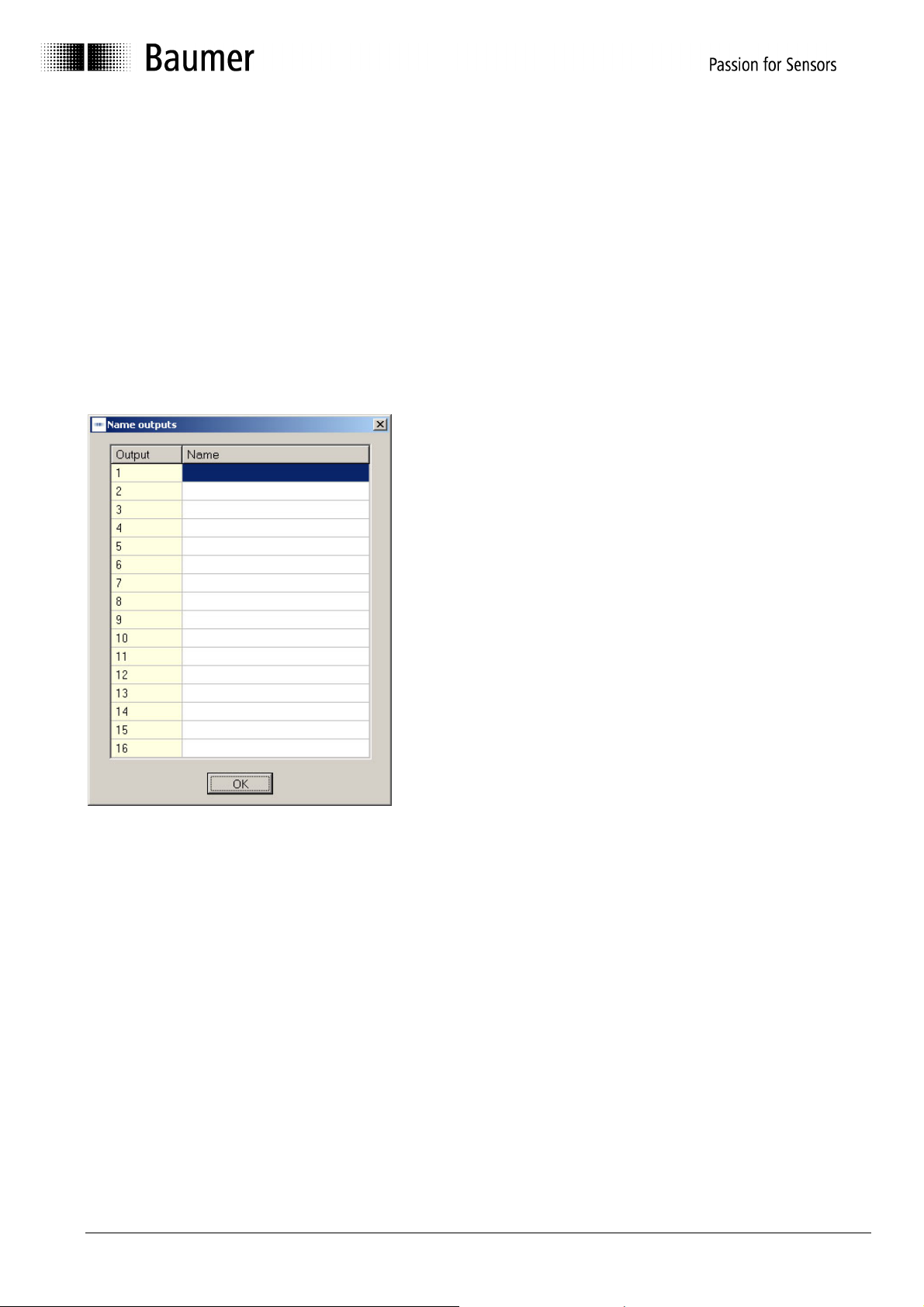
4.5.10 Name outputs
It is possible here to enter a name consisting of up to 16
characters for each output. The names are constantly
visible in the cam tables during programming and
simplify the entry of the switching points in this way.
As the names of the outputs are saved in the encoder
together with the cams, they are not only available on
the PC, but also on any connected display and operating
device.
Manual_ProCam_V1-10_EN.doc 28/35 Baumer IVO GmbH & Co. KG
10.05.11 Villingen-Schwenningen, Germany
Page 29

4.5.11 Enter DTC values
Compensation times can be entered here to compensate
delay times with connected devices and processes.
Regardless of the current speed, the outputs are
switched earlier by the entered time.
The time unit in this window is milliseconds, and up to
1,000 ms are possible.
The entry is made separately for each output, i.e. always
"path-by-path". In addition, different values can be
specified for the switch-on and switch-off time.
4.5.12 Lock outputs
Each output can be locked individually, i.e. protected
against accidental changes.
If cams are entered which act on a locked output, the
password is requested. The password is also required to
release locked outputs for changes again later.
The password set at the factory is "0000" (also see
Chapter 4.1.3).
Permissible parameters for the entry are "0" (free) or
"1" (locked). During the entry of the cam tables, the
locking status is always visible as a lock symbol.
Manual_ProCam_V1-10_EN.doc 29/35 Baumer IVO GmbH & Co. KG
10.05.11 Villingen-Schwenningen, Germany
Page 30

4.6 "Display position" and "Activate cam program" mask
The display module can display the position and the special outputs
of the connected encoder.
This can be selected under "Extras ⇒ Display position".
After the display module starts, the following mask appears.
4
1
2
5
3
7
6
No. Field
1 Total range
2 Total resolution bar display
3 Display of mechanical shaft position
4 Display of speed (scaled)
5 Display of switching state of outputs
6 Display of active program
7 Start or stop cam program
Manual_ProCam_V1-10_EN.doc 30/35 Baumer IVO GmbH & Co. KG
10.05.11 Villingen-Schwenningen, Germany
Page 31

Start cam program
Clicking on the "Start" button starts the selected program. All
outputs programmed as cam outputs assume the state
corresponding to the cam position.
Time cams are treated as "Time
expired" during the program start.
Direction cams are set during the
program start with the encoder stopped
as if the encoder had last run in the
positive direction. Positive is the rotating
direction in which the position values
increase. (See Chapter 4.2.2 "Counting
direction" for setting).
Information window during
start
Stop cam program
Clicking on the "Stop" button stops the running program. All cam outputs assume the inactive
state. The inactive state is de-energized for non-inverted outputs, and +UB for inverted
outputs.
The outputs programmed with a special function (e.g. run control, speed monitoring) are
always active.
Manual_ProCam_V1-10_EN.doc 31/35 Baumer IVO GmbH & Co. KG
10.05.11 Villingen-Schwenningen, Germany
Page 32

4.7 "Set position" mask
With this function the cam encoder is assigned a position value
("Preset value").
In the simplest case, the encoder could be set to "0000" in this way to calibrate the mechanical
zero position of the shaft with the display "0000". However, any other position value within the
set encoder resolution can also be transferred here.
To check this, the current position shown continually updated at the top of the window. After
the preset value is transferred with the "Assign position" button, this appears as the current
position at the top of the window.
Example: The encoder resolution has been set to 360 steps/revolution.
The permissible value range for the "Set position" function is 0 - 359 in this case.
Please observe the following note on dependence of the counting direction in the
"Set position" function.
Manual_ProCam_V1-10_EN.doc 32/35 Baumer IVO GmbH & Co. KG
10.05.11 Villingen-Schwenningen, Germany
Page 33

Before assigning a position value, the encoder rotating direction (positive in
clockwise direction or opposite) must be specified and programmed in the encoder.
This information is transmitted to the encoder together with cam tables and other
data as part of the "Send data" function. The "Send data" function should therefore
be carried out once with the final rotating direction before the encoder is assigned a
position value.
The assignment of a position value may lead to a considerable position jump.
This position jump is not reported via the "Data Valid" special output, as it has been
purposely caused. Any running cam program also stops immediately for safety
reasons when a position value is assigned.
Manual_ProCam_V1-10_EN.doc 33/35 Baumer IVO GmbH & Co. KG
10.05.11 Villingen-Schwenningen, Germany
Page 34

5 Connecting Encoder
5.1 Connection between PC and encoder
To realize the simplest possible connection to the PC, the encoder is equipped with an RS232
interface. With this the encoder can be connected directly to the PC. If the transfer distance is
greater than 30 m, it is advisable to use the RS485 interface. In this case an interface
converter with an automatic directional switchover function is required on the PC (not included
in the delivery scope).
5.1.1 Encoder programming connection
To program the encoder via a PC, the wires TxD, RxD and GND must be connected as
follows.
Connection assignment
Encoder
Function
UB Pin 36 RxD Pin 35 Pin 3
GND Pin 37 Pin 5
TxD Pin 34 Pin 2
Jumper 4-6 and
Jumper 7-8
The encoder must also be connected to the power supply (UB/red and GND/blue) via the
device plug.
Accessories: Z 139.009 Programming cable
ProCam programming software
Manual on CD
D-SUB connector,
37-pin
PC Connection
D-SUB, 9-pin
Manual_ProCam_V1-10_EN.doc 34/35 Baumer IVO GmbH & Co. KG
10.05.11 Villingen-Schwenningen, Germany
Page 35

6 Index
Installation · 5
A
Automatic selection · 8
B
Back to main menu · 12
C
Code (steps) · 17
D
Decreasing clockwise · 17
Display module · 30
I
Increasing clockwise · 17
M
Manual selection · 9
N
New · 12
O
Open · 12
Operating system · 5
P
Print · 12
Print setup · 12
Programming mask · 16
R
Request data · 14
Reset · 14
RS232 · 34
RXD · 34
S
Save · 12
Save as · 12
Send data · 14
Steps · 18
T
Tabs · 11
Total resolution · 18
TxD · 34
Manual_ProCam_V1-10_EN.doc 35/35 Baumer IVO GmbH & Co. KG
10.05.11 Villingen-Schwenningen, Germany
 Loading...