

Page 1
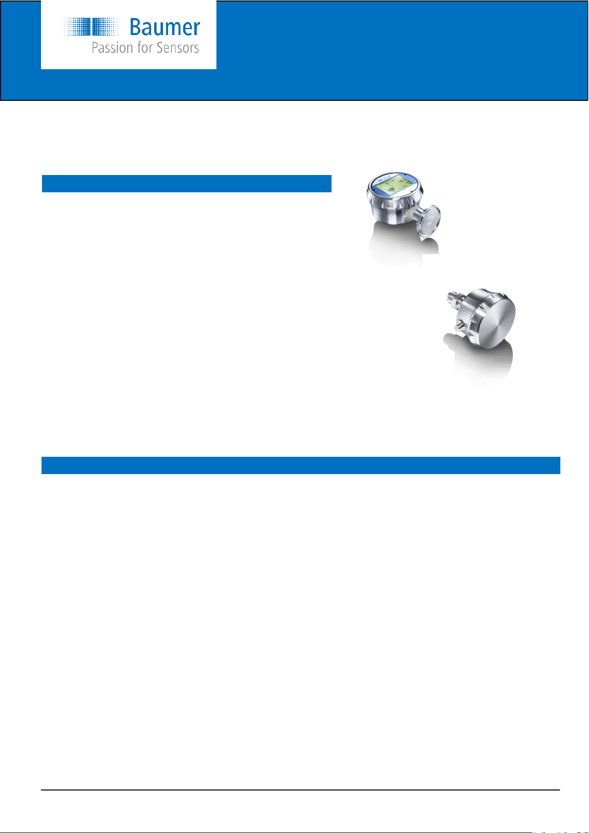
Operators instructions
CombiPress™, type PFMx
CombiPress™ PFMx high end pressure transmitter is made for
measuring pressure in all gaseous and liquid processes, within
ranges from full vacuum (-1 bar) to 400 bar gauge.
Safety instructions
This instrument is built and tested according to the current EUdirectives and packed in a technically safe condition. In order to maintain this condition and to ensure safe operation, the user must follow the
hints and warnings given in this instruction.
During the installation the valid national rules have to be observed. Ignoring the warnings may lead to severe personal injury or substantial
damage to property.
The product must be operated by trained staff. Correct and safe operation of this equipment is dependent on proper transport, storage, installation and operation.
All electrical wiring must conform to local standards. In order to prevent
stray electrical radiation, we recommend twisted and shielded input
cables, as also to keep power supply cables separated from the input
cables. The connection must be made according to the connection diagrams.
Before switching on or off the power supply take care that other equipment is not effected. Ensure that the supply voltage and the conditions
in the environment comply with the specification of the device.
Description
The CombiPress™ PFMN industrial and PFMH hygienic version pressure transmitter is a high end programmable instrument for
measuring pressure from full vacuum to 400 bar gauge pressure or 0 to 400 bar absolute pressure.
CombiPress™ series are supplied to industrial applications with threaded connections or with hygienic connections for hygienic
applications. All wetted parts are in stainless steel AISI 316L (or better). The connection can be mounted as bottom connection or
as rear connection.
PFMx is powered by a 10…35 VDC power supply, featuring an analogue 4...20 mA output signal. A version with 4...20 mA signal
with HART® and an ATEX-version is available.
The CombiPress™ can be mounted with or without a display. The version with display utilizes the Baumer CombiView™ DFON
display, which is connected to the transmitter via the internal UnitCom ribbon cable. The DFON is supplied with power and a digital
signal for measured value, programming etc., which is more reliable and with better accuracy, than using a 4…20 mA loop. In
instruments with UnitCom both the transmitter and display can be programmed at the same time or separate programming of each
device can be selected.
The DFON has a unique background colour setting. Three colours are available – White / Red / Green and further the red and
green colour can be set as flashing as a warning.
The DFON has two integrated galvanic separated relays. The instrument can be delivered with or without activated relays. If supplied without activated relays, those can be activated by purchasing a license code from Baumer. By entering the code to the instrument via the FlexProgrammer the relays are enabled.
The DFON can be programmed by the touch screen on the display or by the FlexProgrammer 9701 Baumer programming unit with
the Baumer FlexProgram installed on a PC.
www.baumer.com
Operators instructions: 11120948 PFMx Page 1 / 12
EN/20131117 Design and specifications subject to change without notice
Page 2
Operators instructions
CombiPress™, type PFMx
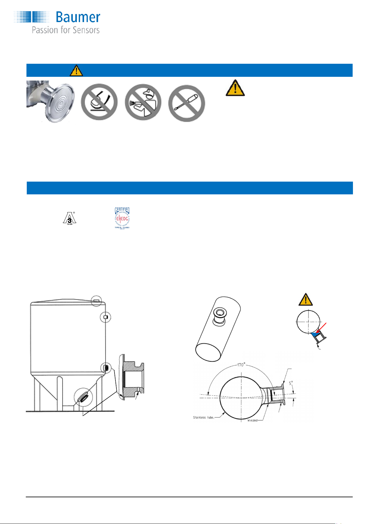
Warning
The diaphragm Don’t No high Use no
is very sensible toutch pressure tools
and easy to destroy cleaning
Mounting
Factory guarantee is void on mechanical damage
of the diaphragm
Don’t touch the diaphragm
Always put on the protection cap if removing
the instrument from the application
Don’t use a high pressure cleaner on the dia-
phragm
Don’t use any tools on the diaphragm, only a
soft brush may be used.
Installation of 3A approved and EHEDG certified products:
1) Use only a 3A approved counter part.
2) The inspection hole should be visible and drained.
3) Mount the instrument in a self drained position.
4) Level the inner surface of the pipe with the counter part.
5) Welding's should be grinded to Ra= 0.8
Tighten the connection with a torque of:
PFMN G½A/G1A 20 Nm
WARNING
Cannot be
drained
Fitted
incorrect
Example
with 8126928
Example
with 8126916
After installation and configuration
Check the leak tightness between the welding
sleeve and the instrument
Check the tightness of glands or M12 plugs.
Check the tightness of the instrument cover
www.baumer.com
Leakage indication hole
must be placed downwards
Operators instructions: 11120948 PFMx Page 2 / 12
Page 3
Operators instructions
CombiPress™, type PFMx
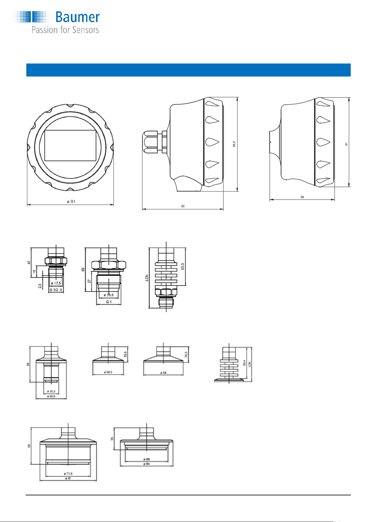
Dimensions
Housing Housing Housing
Diameter Bottom connection Rear connection
Connections for industrial pressure transmitter PFMN
Connection 41 Connection 44 Connection with
G½A G1 conical cooling neck
High temperature types
Standard High temp. LCN:
Code 41 → Code 71 77 mm
Code 44 → Code 74 89 mm
Connections for hygienic pressure transmitter PFMH
Connection 50 Connection 51 Connection 54 Connection with
3A DN 38 ISO 2852 DN 38 ISO 2852 DN 51 cooling neck
High temperature types
Standard High temp. LCN:
Code 51 → Code 81 51 mm
Code 54 → Code 84 51 mm
Connection 56 Connection 61
3A DN 76 Variline® type N
www.baumer.com
Operators instructions: 11120948 PFMx Page 3 / 12
Page 4
Installation
Operators instructions
CombiPress™, type PFMx
If the transmitter is visibly damaged, it should not be put into
operation.
The pressure diaphragm must not be touched during installation. Cleaning with high pressure cleaners and tools may damage the diaphragm.
If the transmitter has a G½A connection, check before mounting that the depth of the hole is at least 20 mm.
For correct installation in 3A connections please see page 2.
Mounting the pressure transmitter in a closed system (e.g. a
valve) may create overpressure higher than permitted, which
can deform and damage the diaphragm.
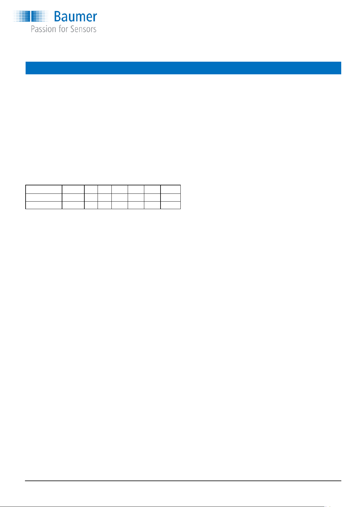
Measuring ranges and over pressure safety
Cell range, bar 0...0,345 -1...1 -1...5 -1...20 -1...34 -1...68 -1...400
Over pressure 1 3 15 60 70 135 690
Burst pressure 2 6 30 120 170 270 1.350
The freezing point of the filling liquid must not be exceeded
White oil -10°C
Silicone oil -40°C
The maximum temperature for the filling liquid is 200°C.
Though the maximum temperature is limited by the mechanical
construction for standard connection to 125°C.
During CIP the temperature may reach 150°C for max. 1 hour.
Installation procedure
The pressure transmitter can change zero point slightly, owing to
mechanical tension and the fitting direction selected for the pressure diaphragm. Optimal results are therefore achieved if the
zero point is adjusted after the pressure transmitter has been
mounted in place in the application.
Electrical installation
Suitable cables should be used to secure maximum tightness in
the gland. For models having a plug for electrical connection the
inner part of the plug must be oriented in a way so that the opening is turning downwards.
To avoid measuring errors resulting from insufficient supply voltage, the transmitter must be supplied with min. 10 VDC at 23
mA. When mounted with DFON display the minimum voltage will
be 14,5 or 16,5 VDC, depending on the setting of the background light.
The transmitter has a high immunity against high-frequency interference. In environments with a high radiation it is recommended to use screened and twisted cable.
Accuracy, turn down
The specifications for accuracy apply to full scale (FS). at 20°C
However the below results are tested and will under normal conditions apply
Accuracy: 0,10%/FS@20°C will apply for up to 2:1 turn down
0,25%/FS@20°C will apply for up to 4:1 turn down
a) Remove protection-cap.
b) Install CombiPress™ in the application
c) Connect the power supply
d) If needed, configure span by the touch screen, FlexPro-
grammer or a HART configurator.
e) If needed, configure the 0-point (4 mA) by pressing the
0-botton for about 5 second (slow blinking diode in app.
5 sec after which the diode will blink fast and the 0-point is
set) or use the facility in the FlexProgrammer or the HART
configurator.
The electronic zero point can be adjusted from -10...10% of the
measuring range.
The correct zero point pressure must be established prior to
adjusting the zero point. Tank and pressure transmitter must
have the same temperature. If the pressure transmitter has a
relative measuring cell from 0 bar, the zero point pressure is the
same as the atmospheric pressure or the level in a tank selected as zero point level. A pressure transmitter measuring absolute pressure has a zero point lower than 1 mbar abs.
You can revert to the factory set zero point correction by recon-
figuring the CombiPress™ with the FlexProgrammer and select-
ing factory setting.
www.baumer.com
Operators instructions: 11120948 PFMx Page 4 / 12
Page 5

Operators instructions
CombiPress™, type PFMx
CombiView™ DFON display
There are 9 different display modes available
Digital Analogue Bar graph Tank
small analogue horizontal tank illustration
large same w. bar graph vertical bottle illustration
same w. value
Electrical connection
Electrical connection
M12, 5-wire M12, 8-wire
1 + supply, 4...20 mA 1 n.c.
2 Common for relays 2 + supply, 4...20 mA
3 - supply, 4...20 mA 3 Relay 1
4 Relay 1 4 Relay 1
5 Relay 2 5 Relay 2
6 Relay 2
7 - supply, 4...20 mA
8 n.c.
Electrical connection
Pin 1 + 4…20 mA (not connected)
Pin 2 - 4…20 mA (not connected)
Pin 3 Relay 1
Pin 4 Relay 1
Pin 5 Relay 2
Pin 6 Relay 2
Com 1 FlexProgrammer ① red
Com 2 FlexProgrammer ② black
The PFMx with DFON display is delivered with terminal 1 and 2 not connected. The DFON is powered and will have data direct
through a special ribbon cable (UnitCom). Via UnitCom the DFON and PFMx transmitter can be programmed together when connecting the FlexProgrammer to Com 1 and COM 2 on the back of the display.
Cable gland
Transmitter
- - supply, 4...20 mA
+ + supply, 4...20 mA
Com 1 Red clip (FlexProgrammer)
Com 2 Black clip (FlexProgrammer)
Display
1 n.c.
2 n.c.
3 Relay 1
4 Relay 1
5 Relay 2
6 Relay 2
Com 1 Red clip (FlexProgrammer)
Com 2 Black clip (FlexProgrammer)
UnitCom
Pin 3 and 5 can be jumpered together if common supply is used for the two relays, e.g. via a M12 5-pin connector. Two galvanic
separated relay outputs will require a 8-pin M12 connector if plug connection is required. If cable glands is used the terminals 4...6
is connected via the screw terminals.
www.baumer.com
Operators instructions: 11120948 PFMx Page 5 / 12
Page 6

Operators instructions
CombiPress™, type PFMx
Touch screen programming the CombiView™, type DFON
Programming CombiView™, type DFON using the touch screen on the display
Tap on the display screen and the button will appear in the bottom.
Press and the display will start with the below menu.
With a transmitter communicating with the DFON via UnitCom ribbon cable
Instrument name menu
transmitter will automatically be uploaded in the display.
Display menu
in the display and also if a level measurement is wanted e.g. a volume or weight acc. to the pressure.
Data display mode
In this mode the display will communicate directly with the transmitter digitally, which is more accurate than using
the 4…20 mA communication.
For programming configuration please see page ?
For programming Display setup and Diagnostics please see page ?
MENU
Display menu
Enabling to the user to programme the connected transmitter through the DFON display. All data programmed into the
Enabling to the user to programme the DFON display only. This is necessary for programming the ColourView and relays
Enabling to the user to programme the connected transmitter and the programmed values will also be valid for the DFON
display. (Ignoring whatever setup already set on the display)
Only programming of background colours and relays must be done under “Display menu” / “Configuration”.
Instrument name menu
MENU
Display setup
Data display mode
Instrument name menu
Instrument name menu
Instrument name menu
Instrument name menu
Instrument name menu
Programming the PFMx/DFON mounted on the application on site using either the touch screen or the FlexProgrammer .
If mounted with DFON the ribbon cable (UnitCom) must not be disconnected after installation and power up of the PFMx. If this
happens the transmitter cannot “see” the display. To enable the PFMx to “see” the DFON again, please disconnect the power
supply to the transmitter, reconnect the ribbon cable (UnitCom) and connect the power supply again.
Programming the CombiPress™, type PFMx with the FlexProgram and FlexProgrammer
Guidance on programming of CombiPress™ PFMx with the DFON display using FlexProgram on your PC and the FlexProgram-
mer hardware tool will not be described here. A full manual for this is available on Baumer home page.
Please see or download the instruction from below internet address:
www.baumer.com → download → product documentation → assembly instructions/Operation instructions/Manuals → Programming the DFON
www.baumer.com
Operators instructions: 11120948 PFMx Page 6 / 12
Page 7

Operators instructions
CombiPress™, type PFMx
Touch screen programming the CombiView™, type DFON
Identification
TAG No. / Serial No. / Date / Prod. date
Display menu
Configuration
Input
Display output
Error/warning
Relay setup
Input 100%
Input 0%
Damping
Linearization
Display 100%
Display 0%
Decimals
Units
Rel. / Abs.
High error
High warning
Low error
Low warning
Relay 1 mode
Rel. 1 set point
Rel. 1 reset point
Relay 1 mode
Rel. 1 set point
Rel. 1 reset point
This menu section is only available when the relays are activated
Current at 100% (20 mA)
Current at 0% (4 mA)
0 = off / 1...30 sec.
Enable / Disable
Display value at 100%
Display value at 0%
Number of digits point
Select from list
Select CUSTOM / create
Select, when pressure
High error limit
High error indication
High error back light
See High error
See High error
See High error
AO / AC / NO / NC
Point at relay ON
Point at relay OFF
AO / AC / NO / NC
Point at relay ON
Point at relay OFF
Display setup
Diagnostics
www.baumer.com
Screen layout
Back light
Password
Attached
Statistics
Demo setup
Standard screen
Specific screen
This menu section is only available when synchronized via UnitCom
Colour
Intensity
Password enable
New password
Attached instr.
Att. Instr. menu
Min. / Max. value
High / Low errors
Demo mode Disabled / Static / Cyclic
Static value
Factory setting
Service menu
Operators instructions: 11120948 PFMx Page 7 / 12
Select display design
Select display design
Point at relay OFF
Point at relay OFF
Enable / Disable
Create new password
Display name of A.I.
Instr. Specific menu
Insert value
Load factory setting
For service personnel
Page 8

Operators instructions
CombiPress™, type PFMx
CombiPresS™ w./w.o. DFON - ATEX specifications and instruction
PFMx Zone 0 Gas: II 1 G, Ex ia IIC T5 Ga
Zone 20 Dust: II 1D, Ex ia IIIC T100°C Da
Zone 2 Gas: II 3G, Ex nA II T5
Please ensure that special requirements for installation in the specific environment is followed, as described below.
Safety instructions
This instrument is constructed and tested according to the current EU directives and packed in a technically safe condition. In
order to ensure safe conditions and operation, the user must follow the instructions and warnings given in this instruction and the
standard operation instruction.
During the installation the valid national rules have to be observed. Ignoring the instructions may lead to severe personal injury or
substantial damage to property.
The product must be installed and operated by trained staff. Correct and safe operation of this equipment is dependent on proper
installation and operation.
All electrical wiring must conform to local standards and the connection must be made according to the connection diagrams on
the following pages.
Before switching on the power supply take care that other equipment is not affected. Ensure that the supply voltage and conditions in the environment comply with the specification of the device.
Before switching off the supply voltage check the possible effects on other equipment and processing system.
To obtain the specified ingress protection degree, the CombiPress™, type PFMx must be mounted with a compliant cable.
Warning
This product is allowed to be operated in an explosion hazardous atmosphere of zone 0 only if atmospheric conditions exists
(temperature –20°C…+60°C and pressure from 0,8...1,1 bar). Under other atmospheric conditions the certificate may be used as a
guide.
Use of FlexProgrammer 9701 is only allowed in the safe area, not in the hazardous area.
Impact test of the display cover is performed according to EN 60079-0, with low impact energy of 2J and does not create a crack or
other intrusion into the housing. However the display, which is mounted close to the front cover may be damaged, but this will not
create any external sparking. The housing is impact texted also according to EN 60079-0, with low impact energy of 4J on housing,
connectors and cable gland.
This product contains no replaceable parts. In case of malfunction the products must be shipped to Baumer for repair.
www.baumer.com
Operators instructions: 11120948 PFMx Page 8 / 12
Page 9

Operators instructions
CombiPress™, type PFMx
ATEX Gas ia and for ATEX Dust ia
For ATEX ia Gas zone 0 and ATEX ia Dust zone 20 a zener barrier must separate the hazardous and safe area and must be installed in accordance with prevailing guidelines for zone 0 / zone 20.
ATEX ia Gas / Dust data:
Approval: Gas Zone 0/1 II 1 G, Ex ia IIC T5 Ga
Dust Zone 20/21 II 1 D, Ex ia IIIC T100°C Da
Voltage drop U
Temperature class T1…T5 Zone 0 and 20 -20°C…60°C
Zone 1/2 and 21/22 -40°C…65°C
Internal inductivity Li <10 µH
Internal capacity Ci <15 nF
Barrier data Ui <30 VDC
Ii <0,1 A
Pi <0,75 W
Suitable barrier e.g.: Pepperl+Fuchs, Z728
4,5 or 6,5 VDC
Disp
The display is supplied via the UnitCom from the transmitter. However to make the transmitter/display intrinsic safe a zener barrier
must be inserted before the PFMx/DFON. As the CombiView™, type DFON is attached to a Baumer PFMx transmitter using the
UnitCom ribbon cable, it is considered to be an integrated part of the instrument.
If the relays are enabled, each relay must be protected by a zener barrier. Use a barrier for each relay or a barrier with multiple
channels. However the two relays must have each a barrier.
Barrier data U <30 VDC
I <75 mA
P <0,75 W
Suitable barrier e.g.: Pepperl+Fuchs, Z779
Electrical connection
PFMx without relay output PFMx with relay output
1 +
1 +
2 -
Zener
barrier
15…30 VDC
2 -
3
Relay 1
4
5
Relay 2
6
Zener
barrier
Zener
barrier
Zener
barrier
15…30 VDC
0…30 VDC
75 mA
0…30 VDC
75 mA
www.baumer.com
Operators instructions: 11120948 PFMx Page 9 / 12
Page 10

Operators instructions
CombiPress™, type PFMx
ATEX Gas nA
For ATEX nA zone 2 is approved without using zener barrier to separate the hazardous and safe area and must be installed in
accordance with prevailing guidelines for zone 0.
ATEX data:
Approval: Gas Zone 2 II 3 G, Ex nA II T5
Voltage drop U
Temperature class T1…T5 -30 < T
4,5 or 6,5 VDC
Disp
amb
<65°C
Internal inductivity Li <10 µH
Internal capacity Ci <15 nF
Maximum voltage U
Maximum current I
Display without relay output Display with relay output
<35 VDC
max
<0,1 A
max
1 +
2 -
4…20 mA
1 +
2 -
3
4
5
4…20 mA
Relay 1
Relay 2
6
Programming the CombiPress™ w./w.o. DFON in ATEX area
Programming the CombiPress™ and the CombiView™, in hazardous area with the FlexProgrammer is not allowed, as the FlexProgrammer (and/or the PC) is not ATEX approved for use in hazardous area.
Follow below procedure to programme the instrument:
a Disconnect mains from the 4…20 mA loop circuit
b Disconnect the instrument from the circuit within the hazardous area
c Uninstall the instrument and bring it to safe area
d Connect the FlexProgrammer and perform the configuration session.
e Re-install the instrument in the hazardous area
f Connect the instrument to the circuit
g Connect mains from the 4…20 mA loop circuit
www.baumer.com
Operators instructions: 11120948 PFMx Page 10 / 12
Page 11

Operators instructions
CombiPress™, type PFMx
www.baumer.com
Operators instructions: 11120948 PFMx Page 11 / 12
Page 12

Operators instructions
CombiPress™, type PFMx
Baumer AG
Hummelstrasse 17
8501 Frauenfeld
Switzerland
+41 51 / 75 81 122
+41 52 / 72 81 144
sales.ch@baumer.com
www.baumer.com
Baumer A/S
Runetoften 19
8210 Aarhus V
Denmark
+45 8931 7611
+45 8931 7610
sales.cc-lct@baumer.com
Contact your local Baumer company
or Baumer distributor.
Please see:
www.baumer.com/worldwide
Select your country
Select your contact
Operators instructions: 11120948 PFMx Page 12 / 12
 Loading...