

Page 1
Betriebsanleitung
Prozessanzeigen
PA201
Operating
Instructions
Process displays
PA201
Guide
utilisateur
Afficheur de process
PA201
Inhalt Seite
Allgemeines /
1
Sicherheitshinweise 2
Beschreibung 4
2
Systembeschreibung 4
2.1
Gerät anschliessen 4
3
Anschlussbelegung 4
3.1
Ein- und Ausgänge 5
3.2
Betriebsspannung anschl. 5
3.3
Anschlussbeispiele 5
3.4
Bedienerebene -
4
Programmierebene 6
Eingangskonfiguration 7
4.1
Anzeigen-Konfiguration 7
4.2
Programmierung sperren 7
4.3
Technische Daten 8
5
Abmessungen 9
5.1
Bestellbezeichnung 9
6
Baumer IVO GmbH & Co. KG
Content Page
General /
Safety instructions 12
Description 14
System description 14
Connecting the device 14
Terminal assignment 14
Inputs and outputs 15
Voltage supply connection 15
Wiring examples 15
Operating mode -
Programming mode 16
Input configuration 17
Display configuration 17
Programming lock 17
Technical data 18
Dimensions 19
Part number 19
Dauchinger Strasse 58-62 • DE-78056 Villingen-Schwenningen
Phone +49 7720 942-0 • Fax +49 7720 942-900
www.baumer.com • info.de@baumerivo.com
Subject to modifcation in technic & design.
Contenu Page
Consignes de
sécurité 22
Description 24
Caractéristiques principales 24
Raccorder l‘appareil 24
Raccordement des conn. 24
Entrées / sorties 25
Alimentation 25
Exemples de raccordements 25
Mode consultation et
programmation 26
Configuration de l‘entrée 27
Configuration de l‘affichage 27
Verrouillage de la program. 27
Caractéristiques techniques
Dimensions 29
Références de commande 29
28
03.13 • 171.55.332/1 • 81072483
Irrtum sowie Änderungen in
Technik und Design vorbehalten.
Sauf erreurs et sous réserve de
modifications techniques et design.
Page 2
PA201
Allgemeines
Nachfolgend finden Sie die Erklärungen der verwendeten Symbole
dieser Betriebsanleitung.
Zeichenerklärung
Kursivschrift Zum schnellen Auffinden von Informationen sind wichtige Begriffe in
der linken Textspalte kursiv wiedergegeben.
Dieses Zeichen bedeutet ausführende Tätigkeiten.
● Dieses Zeichen steht für ergänzende technische Informationen.
Dieses Symbol steht vor jenen Textstellen, die besonders zu
beachten sind, damit der ordnungsgemässe Einsatz des Gerätes
gewährleistet ist.
Dieses Symbol steht vor jenen Textstellen, die zusätzliche wichtige
Informationen liefern.
1 Sicherheitshinweise
Allgemeine Hinweise
Das Gerät ist nach den anerkannten Regeln der Technik entwickelt
und gebaut worden. Das Gerät hat das Herstellerwerk betriebsbereit
und in sicherheitstechnisch einwandfreiem Zustand verlassen!
Um diesen Geräte-Status zu erhalten, ist es erforderlich, dass Sie
das Gerät
- bestimmungsgemäss,
- sicherheits- und gefahrenbewusst,
- unter Beachtung dieser Betriebsanleitung und insbesondere dieser
Sicherheitshinweise installieren/betreiben!
Stellen Sie sicher, dass das Personal die Betriebsanleitung, und hier
be sonders das Kapitel „Sicherheitshinweise“, gelesen und verstanden hat. Ergänzend zur Betriebsanleitung sind allgemeingültige gesetzliche und sonstige verbindliche Regelungen zur Unfallverhütung
und zum Umweltschutz zu beachten und sicherzustellen.
Diese Anleitung ist eine Ergänzung zu bereits vorhandenen Dokumentationen (Datenblatt, Montageanleitung, Katalog).
Bestimmungsgemässe Verwendung
Das Einsatzgebiet des Gerätes umfasst das Steuern und Überwachen von industriellen Prozessen in der Metall-, Holz-, Kunststoff-,
Papier-, Glas-, Textilindustrie u. ä.
Das Gerät darf nur
- in ordnungsgemäss eingebautem Zustand und den
- entsprechenden Angaben der Technischen Daten betrieben werden
2
www.baumer.com
Page 3
PA201
Der Betrieb ausserhalb der angegebenen Beschreibungen/Parameter
ist nicht bestimmungsgemäss und kann in Verbindung mit den zu
steuernden/überwachenden Anlagen/Maschinen/Prozessen zu
- tödlichen Verletzungen,
- schweren Gesundheitsschäden,
- Sachschäden oder
- Schäden an den Geräten führen!
Die Überspannungen, denen das Gerät an den Anschlussklemmen
ausgesetzt wird, müssen auf den Wert der Überspannungskategorie II
(siehe Technische Daten) begrenzt sein!
Das Gerät darf nicht
- in explosionsgefährdeten Bereichen,
- als Medizingeräte,
- in Einsatzbereichen, die nach EN 61010 ausdrücklich genannt sind,
betrieben werden!
Wird das Gerät zur Steuerung/Überwachung von Maschinen oder
Prozessen benutzt, bei denen infolge Ausfall/Fehlfunktion oder Fehlbedienung des Gerätes
- eine lebensbedrohende Gefahr,
- gesundheitliche Risiken oder
- die Gefahr von Sach- oder Umweltschäden entstehen könnte(n),
dann müssen entsprechende Sicherheitsvorkehrungen getroffen
werden!
Manipulationen am Gerät können dessen Funktionssicherheit negativ
beeinflussen und somit Gefahren hervorrufen!
Führen Sie keine Reparaturen am Gerät durch! Schicken Sie defekte
Geräte an den Hersteller zurück!
Installation/Inbetriebnahme
Bei Veränderungen (einschliesslich des Betriebsverhaltens), die die
Sicherheit beeinträchtigen, ist das Gerät sofort ausser Betrieb zu setzen. Bei Installationsarbeiten an den Geräten ist die Stromversorgung unbedingt abzuschalten. Installationsarbeiten dürfen nur von
entsprechend ausgebildeten Fachkräften ausgeführt werden.
Nach korrekter Montage und Installation ist das Gerät betriebsbereit.
Wartung/Instandsetzung
Stromversorgung aller beteiligten Geräte unbedingt abschalten.
Wartungs- und Instandsetzungsarbeiten dürfen nur von entsprechend ausgebildeten Fachkräften ausgeführt werden.
Bei erfolgloser Störungssuche darf das Gerät nicht weiter eingesetzt
werden. Setzen Sie sich bitte mit dem Hersteller in Verbindung.
www.baumer.com
3
Page 4
PA201
2 Beschreibung
2.1 Systembeschreibung
Die Prozessanzeige eignet sich zu Darstellung von Temperaturen in
industriellen Einsatzgebieten.
- Eingang für Thermoelemente J, K, T und Pt100
- Anzeige in °C (1/10 °C) oder °F (1/10 °F)
- LED-Anzeige, 4-stellig und programmierbar
- DIN-Gehäuse 48 x 24 mm
Anzeige
4-stellige Anzeige
Fläche für Einheitenaufkleber
3 Gerät anschliessen
In diesem Kapitel werden zuerst die Anschlussbelegung sowie einige Anschlussbeispiele vorgestellt.
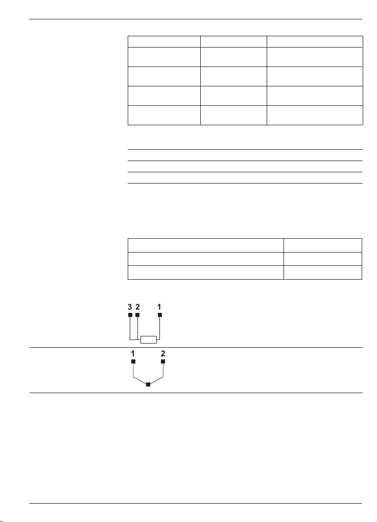
3.1 Anschlussbelegung
$QDORJHLQJlQJH
3W7KHUPRHOHPHQW
3W7KHUPRHOHPHQW
%HWULHEVVSDQQXQJ
3W&RPPRQ
Litzenanschluss aus Gründen des Berührungsschutzes nach
EN61010 nur mittels Aderendhülsen mit Isolierstoffkappen. Vom
Werk unbelegte Anschlüsse nicht anderweitig belegen. Es wird
empfohlen, alle Sensor-Anschlussleitungen abzuschirmen und die
Abschirmung einseitig zu erden. Beidseitige Erdung wird empfohlen
bei HF-Störung und falls bei grösseren Entfernungen PotentialAusgleichsleitungen installiert sind. Die Sensor-Anschlussleitungen
sollen nicht im gleichen Kabelstrang mit der Netzversorgung und den
Ausgangs-Kontaktleitungen geführt werden.
4
www.baumer.com
Page 5
Anschluss Pt100
PA201
3.2 Ein- und Ausgänge
Thermoelement Auflösung (°) Auflösung (0,1°)
Pt100 -200...+800 °C
-328...+1472 °F
-100,0...+200,0 °C
-148,0...+392,0 °F
Thermoelement J -50...+850 °C
-58...+1562 °F
Thermoelement K -50...+1250 °C
-58...+2282 °F
Thermoelement T -200...+400 °C
-328...+752 °F
Analogeingang
Vergleichstellenkompensation -10...60 °C
Messstrom Pt100 <1,3 mA
Leitungswiderstand Max. 40 Ω
3.3 Betriebsspannung anschliessen
Es stehen verschiedene Betriebsspannungen zur Verfügung.
Das Gerät muss netzseitig über die empfohlene externe Sicherung
betrieben werden.
Betriebsspannung externe Absicherung
85...265 VAC, (50/60 Hz) und 100...300 VDC
M 100 mA
21...53 VAC, (50/60 Hz) und 10,5...70 VDC M 500 mA
3.4 Anschlussbeispiel
Anschluss
Thermoelement
Pt100
-
+
Thermoelement
www.baumer.com
5
Page 6
PA201
4 Bedienerebene - Programmierebene
Bedienerebene
Das Gerät befindet sich nach dem Einschalten der Betriebsspannung
automatisch in der Bedienerebene. Es wird der aktuelle Wert angezeigt.
Programmierebene
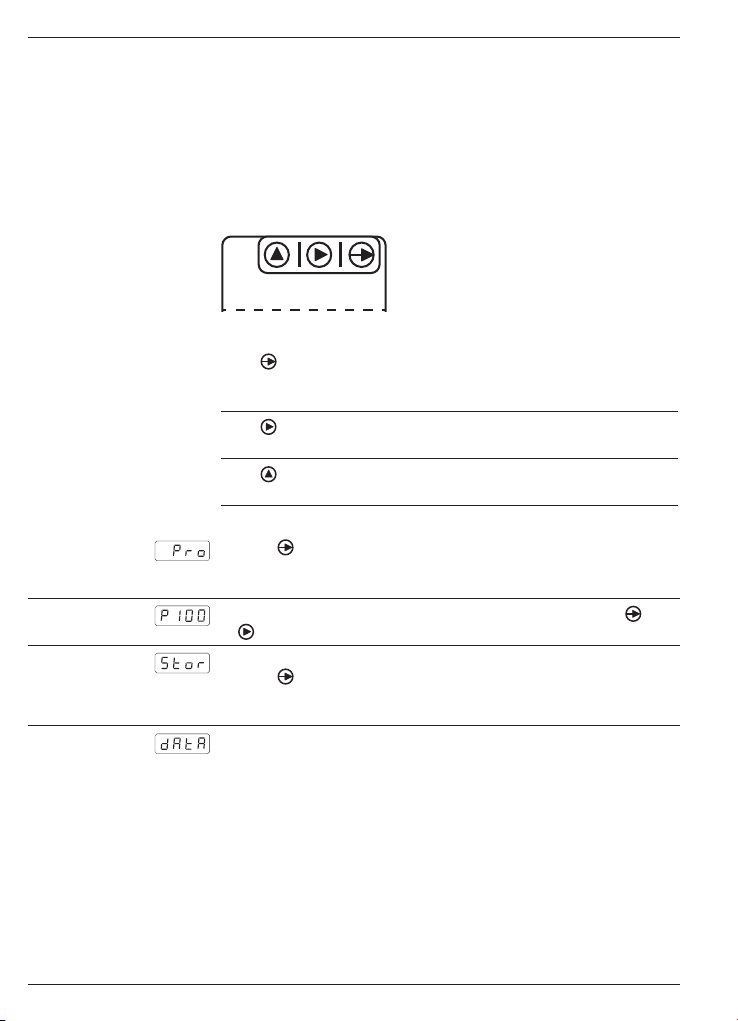
Das Gerät wird mittels drei Tasten parametriert. Diese befinden sich
auf der unteren Seite des Frontrahmens.
Tastatur
(Sicht von unten)
Tastenfunktion
Taste
Dient zum Einstieg in die Programmierebene und zur Auswahl der
Programmierzeile.
Taste
Dient zur Funktionsauswahl in der Programmierzeile.
Taste
Ohne Funktion.
Programmiervorgang
1. Taste drücken, [Pro] wird angezeigt für Einstieg in die Programmierung. Nach wiederholtem Tastendruck erscheint die erste
Programmierzeile (Auswahl Eingangsignal).
2. Die benötigten Programmierzeilen mittels der zwei Tasten und
parametrieren.
3. Nach der letzten Programmierzeile werden, durch Drücken der
Taste , die Parameter automatisch gespeichert und kurz [Stor]
angezeigt bevor das Gerät selbstständig die Programmierebene
verlässt.
4. Der Einstieg in die Programmierung kann in der Programmierebene gesperrt werden. Die verschiedenen Programmierzeilen
können dann nur visualisiert aber nicht geändert werden. Beim
Einstieg in die Programmierebene erscheint dann [dAtA] anstelle
von [Pro].
6
www.baumer.com
Page 7
PA201
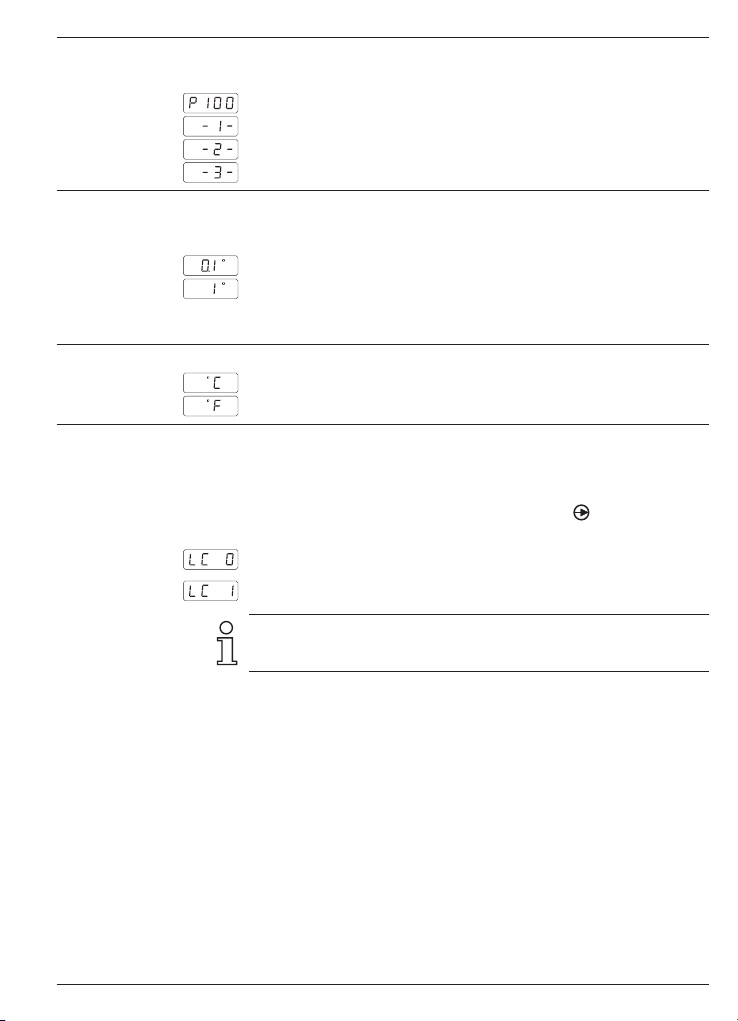
4.1 Eingangskonfiguration
Auswahl Eingangsignal
Pt100
Thermoelement J
Thermoelement K
Thermoelement T
4.2 Anzeige-Konfiguration
Auflösung (*)
Auflösung in 1/10 Grad
Auflösung in Grad
(*) Die Auflösung ist bei Thermoelementen nicht programmierbar,
die Anzeige erfolgt immer in Grad.
Anzeige-Einheit
Grad Celsius
Grad Fahrenheit
4.3 Programmierung sperren
Der Zutritt zur Programmierzeile „Programmierung sperren“
erfolgt am Ende der Anzeige-Konfiguration wie folgt:
Nach Auswahl Anzeige-Einheit (°C oder °F Taste)
halten. Ziffer 0 oder 1 bei “LC“ eingeben.
Programmiersperre inaktiv
Programmiersperre aktiv
Wenn die Programmierung gesperrt ist können die Programmierzeilen nur noch visualisiert, aber nicht geändert werden. Beim Einstieg
in die Programmierebene erscheint dann [dAtA] anstelle von [Pro].
5 s gedrückt
www.baumer.com
7
Page 8

PA201
5 Technische Daten
Technische Daten - elektrisch
Betriebsspannung 21...53 VAC (50/60 Hz) oder
10,5...70 VDC
85...265 VAC (50/60 Hz) oder
100...300 VDC
Leistungsaufnahme 1,8 W
Anzeige LED, 7-Segment Anzeige (mit 60
Einheitenaufkleber für Front)
Stellenzahl 4-stellig
Ziffernhöhe 10 mm
Anzeigenbereich -1999...9999 („OuE“ als overflow
Anzeige)
Anzeigenrefresh 250 ms
A/D-Wandler Prinzip ∑∆
Auflösung 16 Bit
Messrate 25/s
Messgenauigkeit:
Pt100 1° ±(0,2%+1Digit)
Pt100 0,1° ±(0,2%+4Digit)
Temperaturkoeff. 100ppm/°C
Thermoelement ±(0,4 % +2 Digit)
Analogeingang Temperatur: Pt100,
Thermoelemente J,K,T
Programmierbare Messbereich
Parameter Auflösung 0,1 oder 1 °C/°F
Einheit °C/°F
Datenspeicherung >10 Jahre im EEPROM
Auslegung Schutzklasse II
DIN EN 61010-1 Überspannungskategorie II
Verschmutzungsgrad 2
Störaussendung DIN EN 61000-6-3
Störfestigkeit DIN EN 61000-6-2
8
www.baumer.com
Page 9
PA201
Technische Daten - mechanisch
Umgebungstemperatur -10...+60 °C
Lagertemperatur -25...+85 °C
Relative Luftfeuchte 95 % nicht betauend
Anschluss Federkraftklemme steckbar
Aderquerschnitt 1 mm² (Raster 2,54)
2,5 mm
2
(Raster 7,62)
Schutzart DIN EN 60529 IP 65 (frontseitig)
Bedienung / Tastatur 3 Kurzhubtasten unter Frontrahmen
Gehäuseart Einbaugehäuse
Abmessungen B x H x L 48 x 24 x 106 mm
Montageart Frontplatteneinbau mit Spannrahmen
Werkstoffe Gehäuse: Polycarbonat UL 94V-0
Masse ca. 50 g
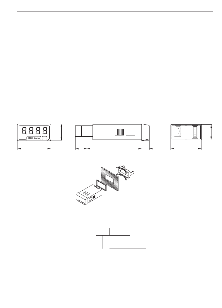
5.1 Abmessungen
PA201 - ohne Spannrahmen
PA201 - Spannrahmenmontage
6 Bestellbezeichnung
PA201.00 AX01
4 85...265 VAC und 100...300 VDC
5 21...53 VAC und 10,5...70 VDC
Betriebsspannung
www.baumer.com
9
Page 10

PA201
10
www.baumer.com
Page 11

Operating
Instructions
Process displays
PA201
Content Pa ge
General / Safety instructions 12
1
Description 14
2
System description 14
2.1
Connecting 14
3
Terminal assignment 14
3.1
Inputs and outputs 15
3.2
Voltage supply connection 15
3.3
Wiring examples 15
3.4
Operating mode - Programming mode 16
4
Input configuration 17
4.1
Display configuration 17
4.2
Programming lock 17
4.3
Technical data 18
5
Dimensions 19
5.1
Part number 19
6
PA201
www.baumer.com
11
Page 12

PA201
General Information
In the following you will find the explanations of the symbols used
in this operating manual.
Explanation of symbols ➜ This symbol indicates activities to be carried out.
● This symbol indicates supplementary technical information.
This symbol is located before texts to which particular attention is to
be paid to ensure proper use of the product.
This symbol is located before texts that provide important additional
information.
Italics Important terms in the left text column are printed in italics to help
you find information more quickly.
1 Safety instructions
General information
The products has been developed and built in accordance with the
recognized rules of technology. The units have left the manufacturing
plant ready to operate and in safe condition.
To keep the units in this condition, it is necessary that the units be
- installed and operated
- properly,
- in a safety and hazard-conscious manner,
- under observance of this operating manual and in particular of
these safety precautions!
Make sure that the personnel has read and understood the operating
manual, and in particular the „Safety Instructions“ chapter.
In addition to the operating manual, the generally applicable legal and
other binding regulations for accident prevention and environmental
protection must be observed and ensured.
This manual is intended as a supplement to already existing documentation (catalogues, data sheets or assembly instructions).
Proper use
The application of the units consists of controlling and monitoring industrial processes in the metal, wood, plastics, paper, glass and textile industry etc.
The units may only be operated
- in the properly installed state and
- in accordance with the specifications of the technical data.
12
www.baumer.com
Page 13

PA201
Operation not covered by the specified descriptions/parameters is
improper and can lead to
- fatal injuries,
- serious damage to health,
- property damage or
- damage to the units
in conjunction with the systems/machines/processes to be
controlled/monitored!
The overvoltages to which the units are subjected at the connection
terminals must be limited to the value of the overvoltage category II
(see Technical data)!
The units may not be operated
- in hazardous areas,
- as medical units,
- in applications expressly named in EN 61010!
If the units are used to control/monitor machines or processes with
which, as the result of a failure/malfunction or incorrect operation of
the units
- a life-threatening danger,
- health risks or
- a danger of property or environmental damage
could result, then appropriate safety precautions must be taken!
Tampering with the units can have a negative affect on their operating safety, resulting in dangers!
Do not make repairs on the units! Return defective units to the manufacturer!
Installation/commissioning
In case of changes (including in the operating behavior) that impair
safety, shut-down the units immediately. During installation work on
the units, the power supply must always be disconnected. Installation work may only be carried out by appropriately trained experts.
Following proper assembly and installation, the units are ready for
operation.
Maintenance/repairs
Always disconnect the power supply of all units involved. Maintenance and repair work may only be carried out by appropriately
trained experts.
If troubleshooting is unsuccessful, do not continue to use the units.
Please contact the manufacturer in this case.
www.baumer.com
13
Page 14

PA201
2 Description
2.1 System description
The process display may be utilized as temperature indicator in
industrial environments.
- Thermocouple input J, K, T and Pt100
- Reading in °C (1/10 °C) or °F (1/10 °F)
- LED display, 4 digits and programmable
- DIN housing 48 x 24 mm
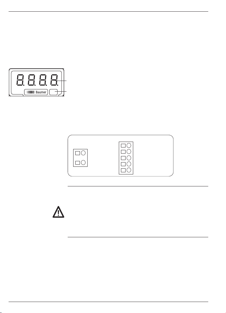
Display
4 digits
Sticker to indicate measuring unit
3 Connection
This chapter is about terminal assignment and will present some
wiring examples.
3.1 Terminal assignment
$QDORJLQSXWV
3WWKHUPRFRXSOH
3WWKHUPRFRXSOH
6XSSO\YROWDJH
3W&RPPRQ
Litz contact only by means of connector sleeves with insulating
enclosures for reasons of shock protection according to EN 61010.
Do not otherwise assign contacts that have been left unassigned ex
factory. We recommend to screen all sensor terminal leads and to
ground the shield on one side. Shields on both sides are recommended in case of RF interference or in case of equipotential bonding
over long distances. The sensor leads should not be in the same
phase winding as the mains supply and the output contact leads.
14
www.baumer.com
Page 15

Connection Pt100
PA201
3.2 Inputs and outputs
Thermo sensor Resolution (°) Resolution (0,1°)
Pt100 -200...+800 °C
-328...+1472 °F
-100.0...+200.0 °C
-148.0...+392.0 °F
Thermocouple J -50...+850 °C
-58...+1562 °F
Thermocouple K -50...+1250 °C
-58...+2282 °F
Thermocouple T -200...+400 °C
-328...+752 °F
Analog input
Cold junction compensation -10...60 °C
Measuring current Pt100 <1.3 mA
Line resistance Max. 40 Ω
3.3 Voltage supply connection
There are several options for operation supply.
Power supply must be fed in via the recommended external fuse.
Operating voltage External protection
85...265 VAC, (50/60 Hz) and 100...300 VDC
M 100 mA
21...53 VAC, (50/60 Hz) and 10.5...70 VDC M 500 mA
3.4 Wiring examples
Connection
Thermocouple
Pt100
-
+
Thermocouple
www.baumer.com
15
Page 16

PA201
4 Operating mode – programming mode
Operating mode
The device is automatically in operating mode after power on,
indicating the actual value.
Programing mode
Device parameterization is by three soft keys located below the front
panel (see below).
Keypad
(view from below)
Key functions
Key
Access programming level and select programming line.
Key
Select functionality or decade in the programming line.
Key
Without function.
How to program
1. Press , display will switch to [Pro] which means access to programming level. Another press will make the display skip to first
programming line (option input signal).
2. Proceed with line parameterization using keys and .
3. Pressing will save the parameters after having them indicated
for short. The device will automatically exit the programming level.
4. Programming access can be disabled at programming level, in this
case programming lines will be read only. The device will signal
any programming lock by [dAtA] instead of [Pro] upon access.
16
www.baumer.com
Page 17

PA201
4.1 Input configuration
Select input signal
Pt100
Thermocouple J
Thermocouple K
Thermocouple T
4.2 Display configuration
Resolution (*)
Resolution in degree 1/10
Resolution in degree
(*) Thermocouple resolution does not enable programming.
Indication is ever in degrees.
Display unit
Degrees Celsius
Degrees Fahrenheit
4.3 Programming lock
Accessing programming line „Programming lock“ is after completion
of display configuration by proceeding as follows:
Select display unit (°C or °F) and hold
Enter 0 or 1 in “LC”.
Programming lock disabled
Programming lock enabled
Programming lock means programming lines are read only which will
be signaled by [dAtA] instead of [Pro] appearing in the display when
accessing programming level.
for 5 seconds.
www.baumer.com
17
Page 18

PA201
5 Technical data
Technical data - electrical ratings
Voltage supply 21...53 VAC (50/60 Hz) or
Power consumption 1.8 W
Display LED, 7-segment display (with 60 unit
Number of digits 4-digits
Digit height 10 mm
Display range
Display refresh 250 ms
A/D transformer Principle ∑∆
Analog input Temperature: Pt100,
Programmable Measuring range
Parameters Resolution 0.1 or 1 °C/°F
Data memory >10 years in EEPROM
Standard Protection class II
DIN EN 61010-1 Overvoltage category II
Emitted interference DIN EN 61000-6-3
Interference immunity DIN EN 61000-6-2
10.5...70 VDC
85...265 VAC (50/60 Hz) or
100...300 VDC
stickers for front)
-1999...9999 („OuE“ to signal overflow)
Resolution 16 bit
Measuring rate 25/s
Measuring accuracy:
Pt100 1° ±(0.2%+1-digit)
Pt100 0.1° ±(0.2%+4-digit)
Temp. coeffic. 100ppm/°C
Thermocouple ±(0.4 % +2-digit)
Thermocouples J,K,T
Measuring unit °C/°F
Pollution degree 2
18
www.baumer.com
Page 19

PA201
Technical data - mechanical design
Ambient temperature -10...+60 °C
Storing temperature -25...+85 °C
Relative humidity 95 % non-condensing
Connection Spring-loaded terminal connector,
detachable
Core cross-section 1 mm² (Grid 2.54)
2.5 mm
2
(Grid 7.62)
Protection DIN EN 60529 IP 65 (face)
Operation / keypad 3 softkeys below bezel
Housing type Built-in housing
Dimensions W x H x L 48 x 24 x 106 mm
Mounting Front panel installation by clip frame
Material Housing: Polycarbonate, UL 94V-0
Weight approx. 50 g
5.1 Dimensions
PA201 - without clip frame
PA201 - clip frame mounting
6 Part number
PA201.00 AX01
4 85...265 VAC and 100...300 VDC
5 21...53 VAC and 10.5...70 VDC
Voltage supply
www.baumer.com
19
Page 20

PA201
20
www.baumer.com
Page 21

Guide
utilisateur
Afficheur de process
PA201
Contenu Page
Consignes de sécurité 22
1
Description 24
2
Caractéristiques principales 24
2.1
Raccorder l‘appareil 24
3
Raccordement des connecteurs 24
3.1
Entrées / sorties 25
3.2
Alimentation 25
3.3
Exemples de raccordements 25
3.4
Mode consultation et programmation 26
4
Configuration de l‘entrée 27
4.1
Configuration de l‘affichage 27
4.2
Verrouillage de la programmation 27
4.3
Caractéristiques techniques 28
5
Dimensions 29
5.1
Références de commande 29
6
PA201
www.baumer.com
21
Page 22

PA201
Généralités
Ci-dessous, vous trouverez des explications sur les symboles utilisés
dans ce guide utilisateur.
Explications symboles
de réaliser une action spécifique.
Ecriture en italique Afin de trouver rapidement certaines informations, les mots clés
sont écrits en italique dans la colonne de gauche.
En face de ce symbole on trouvera des informations permettant
● En face de ce symbole on trouvera des informations techniques
complémentaires.
Ce symbole se trouve devant des informations qu‘il faut observer
tout particulièrement pour garantir une mise en service et un fonctionnement dans les règles de l‘art.
Ce symbole est placé devant des textes fournissant des informations
complémentaires.
1 Consignes de sécurité
Consignes générales
Cet appareil a été développé et fabriqué selon les normes et
prescriptions vigueur. L‘appareil a quitté l‘usine de production prêt à
fonctionner et en parfait état technique vis à vis de la sécurité!
Afin de conserver cet état, il est indispensable d‘installer et d‘utiliser
l‘appareil:
- conformément aux prescriptions
- en étant informé sur les règles de sécurité et les risques
- en respectant ce guide utilisateur et particulièrement les consignes
de sécurité qu‘il contient.
Assurez-vous que le personnel a lu et compris le guide utilisateur et
particulièrement le chapitre „Consignes de sécurité“. Il faut également observer et respecter les règles légales et contractuelles en
vigueur concernant la sécurité des personnes et la protection de
l‘environnement.
Conformité d‘utilisation
Le domaine d‘utilisation de l‘appareil correspond au contrôle et
commande de process industriels dans, entre autres, l‘industrie du
métal, du bois, du plastique, du papier, du verre, du textile...
L‘appareil ne doit être mis en service qu‘après avoir respectés:
- les règles de montage et d‘installations
- les indications et caractéristiques techniques
22
www.baumer.com
Page 23

PA201
La non observation des paramètres, descriptions et prescriptions
peut conduire au niveau des installations, machines ou process à
piloter à:
- des blessures mortelles
- de graves dommages pour la santé
- des dommages matériels
- des dommages sur l‘appareil
Les surtensions auxquelles l‘appareil est soumis au niveau des
bornes de raccordement doivent être limitées à la catégorie II de surtension (Cf. caractéristiques techniques)!
- L‘appareil ne peut pas être utilisé:
- dans les secteurs à risque d‘explosion
- comme appareil médical
- dans les domaines d‘utilisations expressément nommés dans la
norme EN 61010!
Si l‘appareil est utilisé pour la commande ou le contrôle d‘une
machine ou d‘une installation pour laquelle une panne, une erreur de
manipulation de l‘appareil peut produire:
- un risque mortel
- des risques pour la santé
- des risques de dommages matériels ou environnementaux
alors il faut prendre des mesures de sécurité correspondantes!
Des interventions dans l‘appareil peuvent avoir un effet négatif sur la
sécurité de fonctionnement, et par conséquent, être dangereuses.
N‘effectuez aucune réparation sur l‘appareil! Retournez l‘appareil défectueux au constructeur!
Installation / Mise en service
Suite à des modifications ou changement de comportement qui influencent la sécurité, il y a lieu de mettre l‘appareil immédiatement
hors service. Lors des travaux d‘installation de l‘appareil, il faut impérativement couper l‘alimentation. Les travaux d‘installation ne doivent être réalisés que par du personnel qualifié. L‘appareil ne doit
être mis en service qu‘après montage et installation corrects.
Entretien / Maintenance
Couper impérativement l‘alimentation de l‘ensemble des appareils
de l‘installation. Les travaux d‘entretien et de maintenance ne doivent être effectués que par du personnel qualifié. Si la recherche
du dis-fonctionnement reste infructueuse, il ne faut pas remettre
l‘appareil en service. Dans ce cas veuillez contacter le constructeur.
www.baumer.com
23
Page 24

PA201
2 Description
2.1 Caractéristiques principales
L‘indicateur de process est destiné à traiter et afficher des températures dans un environnement industriel.
- Entrée pour thermocouple J,K,T et Pt100
- Unité d‘affichage en °C (1/10 °C) ou °F (1/10 °F)
- Affichage LED, 4 digits programmable
- Boîtier DIN 48 x 24 mm
Affichage
Afficheur 4 digits
Emplacement étiquette d‘unités autocollantes
3 Raccorder l‘appareil
Dans ce chapitre sont présentés les connecteurs de raccordement
ainsi que des exemples de raccordements.
3.1 Connecteurs de raccordements
(QWUpHDQDORJLTXH
3W7KHUPRFRXSOH
3W7KHUPRFRXSOH
$OLPHQWDWLRQ
3W&RPPXQ
Pour se protéger contre le contact direct, l‘extrémité des fils doit
être munie d‘un embout de câblage isolé suivant EN 61010. Ne
rien brancher sur les bornes non utilisées par le constructeur. Il est
recommandé de blinder toutes les lignes de capteurs ou entrées de
commande et de relier le blindage à la terre d‘un coté. Le raccordement du blindage aux deux extrémités est recommandé en milieu
perturbé par des signaux HF ou pour des grandes longueurs de
câbles, à condition qu‘il existe une liaison équipotentielle.
24
www.baumer.com
Page 25

Raccordement Pt100
PA201
3.2 Entrées et sorties
Sonde Résolution (°) Résolution (0,1°)
Pt100 -200...+800 °C
-328...+1472 °F
-100,0...+200,0 °C
-148,0...+392,0 °F
Thermocouple J -50...+850 °C
-58...+1562 °F
Thermocouple K -50...+1250 °C
-58...+2282 °F
Thermocouple T -200...+400 °C
-328...+752 °F
Entrée analogique
Compensation soudure froide -10...60 °C
Courant d‘excitation Pt100 <1,3 mA
Résistance des câbles Max. 40 Ω
3.3 Brancher l‘alimentation
Il existe différentes tensions d‘alimentation.
L‘alimentation de l‘appareil doit être protégée par un fusible externe
dont la valeur est recommandée.
Alimentation Fusible externe
85...265 VAC, (50/60 Hz) et 100...300 VDC M 100 mA
21...53 VAC, (50/60 Hz) et 10,5...70 VDC M 500 mA
3.4 Exemples de raccordements
Raccordement
thermocouple
Pt100
-
+
Thermocouple
www.baumer.com
25
Page 26

PA201
4 Consultation - Programmation
Mode consultation
L’afficheur se trouve dans ce mode à la mise sous tension.
C’est dans ce mode que l’on consulte la valeur de la mesure.
Mode programmation
La programmation de l‘indicateur s‘effectue par trois touches situées
sous la face avant.
Clavier
(Vue de dessous)
Fonctions des touches
Touche
Permet l‘accès au mode programmation et le défilement des différentes lignes à programmer.
Touche
Permet de sélectionner une option dans une ligne de programmation.
Touche
Sans fonction.
Mode opératoire
1. Appuyer sur la touche , le message [Pro] s‘affiche pour confirmer l‘entrée en mode programmation. En appuyant à nouveau sur
la touche apparaît la première ligne de programmation (Choix du
signal d‘entrée).
2. Programmer les différentes lignes à l‘aide des deux touches
et .
3. Par un appui sur la touche après la programmation des différentes lignes de configuration l‘appareil mémorise les modifications en affichant le message [Stor] pendant la sauvegarde, et
quitte automatiquement le mode programmation.
4. L‘accès à la programmation de l‘appareil peut peut être verrouillé dans le mode programmation, mais il sera toujours possible
d‘accéder aux différentes lignes de configuration pour en vérifier
le contenu. Dans ce cas le message [dAtA] sera affiché à la place
du message [Pro] en entrant en mode programmation.
26
www.baumer.com
Page 27

PA201
4.1 Configuration de l‘entrée
Sélection du signal d‘entrée
Pt100
Thermocouple J
Thermocouple K
Thermocouple T
4.2 Configuration de l‘affichage
Résolution (*)
Résolution au 1/10 de degré
Résolution au degré
(*) La résolution n‘est pas programmable pour les thermocouples,
l‘affichage se fait toujours en degré.
Unité d‘affichage
Degré Celsius
Degré Fahrenheit
4.3 Verrouillage de la programmation
L‘accès à la ligne „verrouillage de la programmation“ se fait à la fin
de la configuration de l‘affichage comme suit:
Après avoir fait le choix entre unité d‘affichage (°C ou °F), appuyer et
maintenir la touche
1 suivant le cas.
Verrouillage désactivé
Verrouillage activé
Lorsque la programmation est verrouillée, il est toujours possible
d‘accéder aux différentes lignes de configuration pour en vérifier le
contenu. Dans ce cas le message [dAtA] sera affiché à la place du
message [Pro] en entrant en mode programmation.
pendant 5 s, „LC“ apparaît, sélectionner 0 ou
www.baumer.com
27
Page 28

PA201
5 Caractéristiques techniques
Caractéristiques électriques
Alimentation 21...53 VAC (50/60 Hz) ou
10,5...70 VDC
85...265 VAC (50/60 Hz) ou
100...300 VDC
Consommation 1,8 W
Affichage LED, affichage 7 segments (avec 60
étiquettes d‘unités autocollantes)
Nombre de digits 4 digits
Hauteur des digits 10 mm
Plage d‘affichage -1999...9999 („OuE“ pour dépasse-
ment de capacité d‘affichage)
Rafraîchissement d‘affichage 250 ms
Convertisseur A/D Principe ∑∆
Résolution 16 bit,
Cadence 25/s
Précision: Pt100 1° ±(0,2%+1digit)
Pt100 0,1° ±(0,2%+4digits)
Coeff. de tempér. 100ppm/°C
Thermocouple ±(0,4 % +2 Digit)
Entrée analogique Température: Pt100,
thermoelemente J,K,T
Paramètres Echelle
programmables Résolution 0,1 ou 1 °C/°F
Unité d‘affichage °C/°F
Mémoire >10 ans par EEPROM
Conformité Classe de protection II
DIN EN 61010-1 Surtension catégorie II
Degré de pollution 2
Emission DIN EN 61000-6-3
Immunité DIN EN 61000-6-2
28
www.baumer.com
Page 29

PA201
Caractéristiques mécaniques
Température ambiante -10...+60 °C
Température de stockage -25...+85 °C
Humidité relative 95 % sans condensation
Raccordement Connecteur débrochable à ressort
Section maxi. fils 1 mm² (pour pas 2,54)
2,5 mm
2
(pour pas 7,62)
Indice de protection IP 65 (en façade)
DIN EN 60529
Utilisation / Clavier 3 Touches situées sous la face avant
Type de boîtier Encastrable
Dimensions L x H x P 48 x 24 x 106 mm
Fixation Encastrable fixation par étrier
Matière Boîtier: Polycarbonate, UL 94V-0
Poids 50 g
5.1 Dimensions
PA201 - Sans étrier
PA201 - Montage avec étrier
6 Références de commande
PA201.00 AX01
4 85...265 VAC et 100...300 VDC
5 21...53 VAC et 10,5...70 VDC
Alimentation
www.baumer.com
29
 Loading...