

Page 1
Operating instructions.
OM70 laser point / laser line distance
sensors
Page 2

Contents
1
1.1
1.2
1.3
2
3
3.1
3.1
3.2
3.3
3.4
3.5
4
4.1
4.2
4.3
4.4
4.5
4.6
4.7
4.8
4.9
General information ...................................................................................................................... 3
Concerning the contents of this document ..................................................................................... 3
Intended use ................................................................................................................................... 3
Safety .............................................................................................................................................. 4
Quick start-up guide ..................................................................................................................... 5
Mounting and connections .......................................................................................................... 7
Dimensions ..................................................................................................................................... 7
Sensor reference levels .................................................................................................................. 8
Definition of the measuring range ................................................................................................... 9
Mounting ....................................................................................................................................... 12
Alignment ...................................................................................................................................... 13
Connection .................................................................................................................................... 16
Configuration .............................................................................................................................. 18
Overview of control elements ....................................................................................................... 18
Function tree ................................................................................................................................. 21
LIVE MONITOR ............................................................................................................................ 22
PRECISION .................................................................................................................................. 23
ANALOG OUT .............................................................................................................................. 25
DIGITAL OUT ................................................................................................................................ 28
SYSTEM ....................................................................................................................................... 32
SETTING ...................................................................................................................................... 35
Configuration using the RS-485 interface ..................................................................................... 36
5
5.1
5.2
5.3
5.4
5.5
6
6.1
6.2
6.3
6.4
6.5
7
7.1
7.1
7.1
7.2
7.1
7.2
8
Operation ..................................................................................................................................... 37
Measuring frequency, measuring repeat time and response time ................................................ 37
Alarm output .................................................................................................................................. 37
Influence of ambient light .............................................................................................................. 38
Focus distance and optimal measuring distance.......................................................................... 38
Error correction and tips ............................................................................................................... 40
Safety instructions and maintenance ....................................................................................... 41
General safety instructions ........................................................................................................... 41
Sensor inscriptions ....................................................................................................................... 42
Front optic ..................................................................................................................................... 43
Cleaning the sensors .................................................................................................................... 43
Disposal ........................................................................................................................................ 43
Sensor data sheet ....................................................................................................................... 44
Measuring range types 30…70 mm ............................................................................................. 44
Measuring range types 40…140 mm ........................................................................................... 47
Measuring range types 50…250 mm ........................................................................................... 50
Measuring range types 100…600 mm ......................................................................................... 54
Measuring range types 100…1000 mm ....................................................................................... 57
Measuring range types 150…1500 mm ....................................................................................... 60
Revision history .......................................................................................................................... 63
en_BA_OM70_point_line.docx 2/64 Baumer Electric AG
6/6/2018 8:28 AM/tof V2.0 ANW_81250853 Frauenfeld, Switzerland
Page 3
1 General information
1.1 Concerning the contents of this document
This manual contains information about the installation and initial setup of Baumer OM70 laser point / laser
line sensors.
It is a supplement to the mounting instructions supplied with each sensor.
1.2 Intended use
The Baumer OM70 laser point / laser line sensor measures distances to objects. It was specially developed
for easy handling, flexible use, and highly accurate measurement.
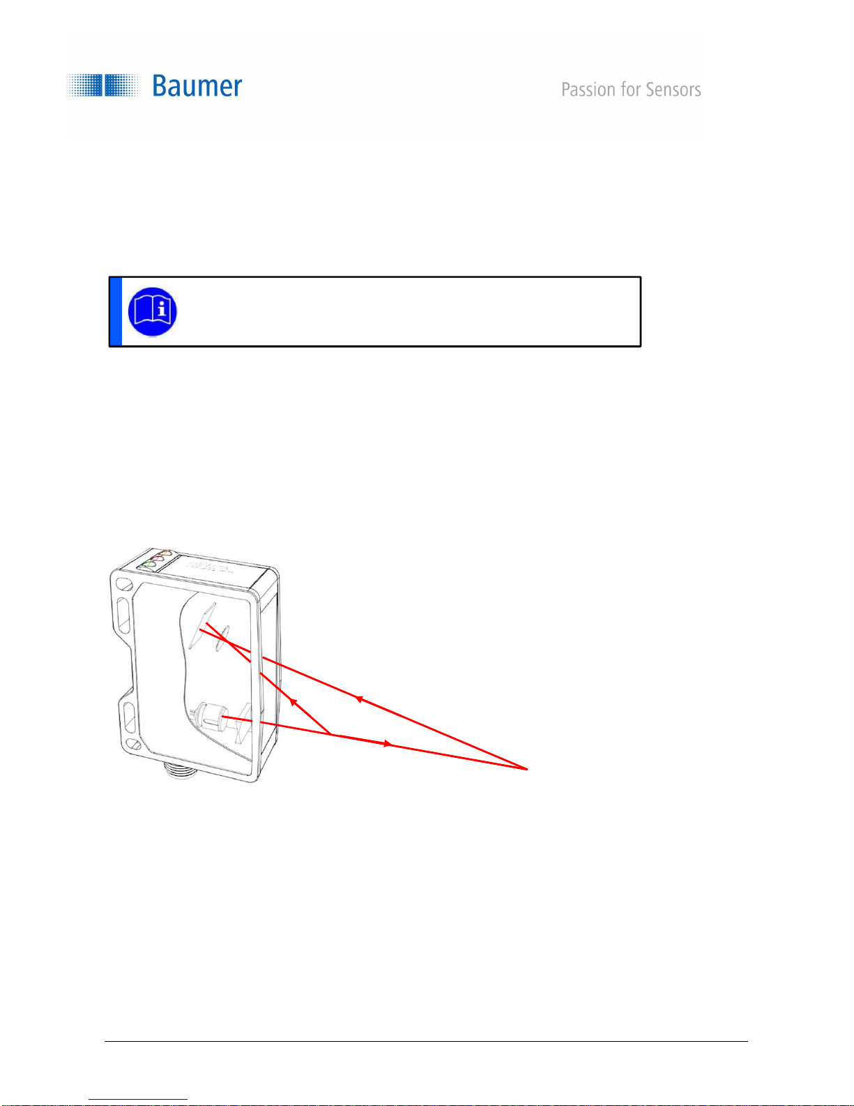
1.2.1 Functional principle of triangulation
Read these operating instructions carefully and follow the safety instructions!
In the triangulation principle, the sensor transmits a light point or light beam to the object to be measured, and
the reflected light strikes a receiver line in the sensor at a special angle. Depending on the distance, the angle
of incidence changes and thus so does the position of the light spot or light beam on the receiver. The microcontroller allows the suppression of interfering reflections, thus providing reliable data even on critical
surfaces.
en_BA_OM70_point_line.docx 3/64 Baumer Electric AG
6/6/2018 8:28 AM/tof V2.0 ANW_81250853 Frauenfeld, Switzerland
Near
Far
Page 4
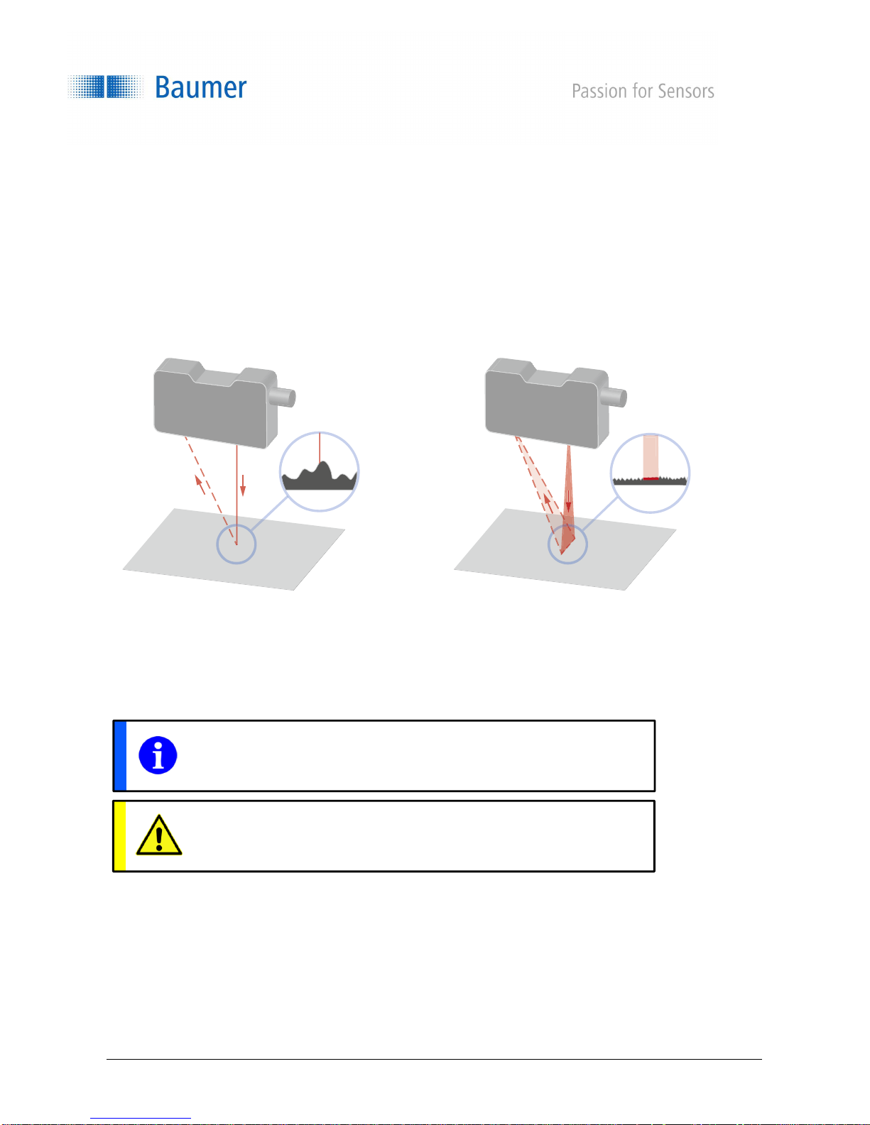
1.2.2 Laser point or laser line
OM70 laser point OM70 laser line
For small objects, if accurate positioning of the laser
point is important, or for sharp transitions, a sensor
with a laser point is suitable.
Stable measurements on rough surfaces and
textured color surfaces thanks to a fine laser line < 10
mm
1.3 Safety
NOTE
Provides helpful operation instructions or other general recommendations.
ATTENTION!
Indicates a potentially hazardous situation. Avoid these situations in order to
prevent any personal injury or damage to the device.
en_BA_OM70_point_line.docx 4/64 Baumer Electric AG
6/6/2018 8:28 AM/tof V2.0 ANW_81250853 Frauenfeld, Switzerland
Page 5
2 Quick start-up guide
Key functions
Rx/Tx+
Rx/Tx-
(2)
BN
1
1
2
4
LANGUAGE
3
After connection and installation, the sensor is configured using the display. The sensor is then ready for
operation and shows the measured value in mm on the screen. Optionally, the analog output can also be
limited or the switching output configured.
Connection
Installation
Application-specific settings
Let's get started
Connection
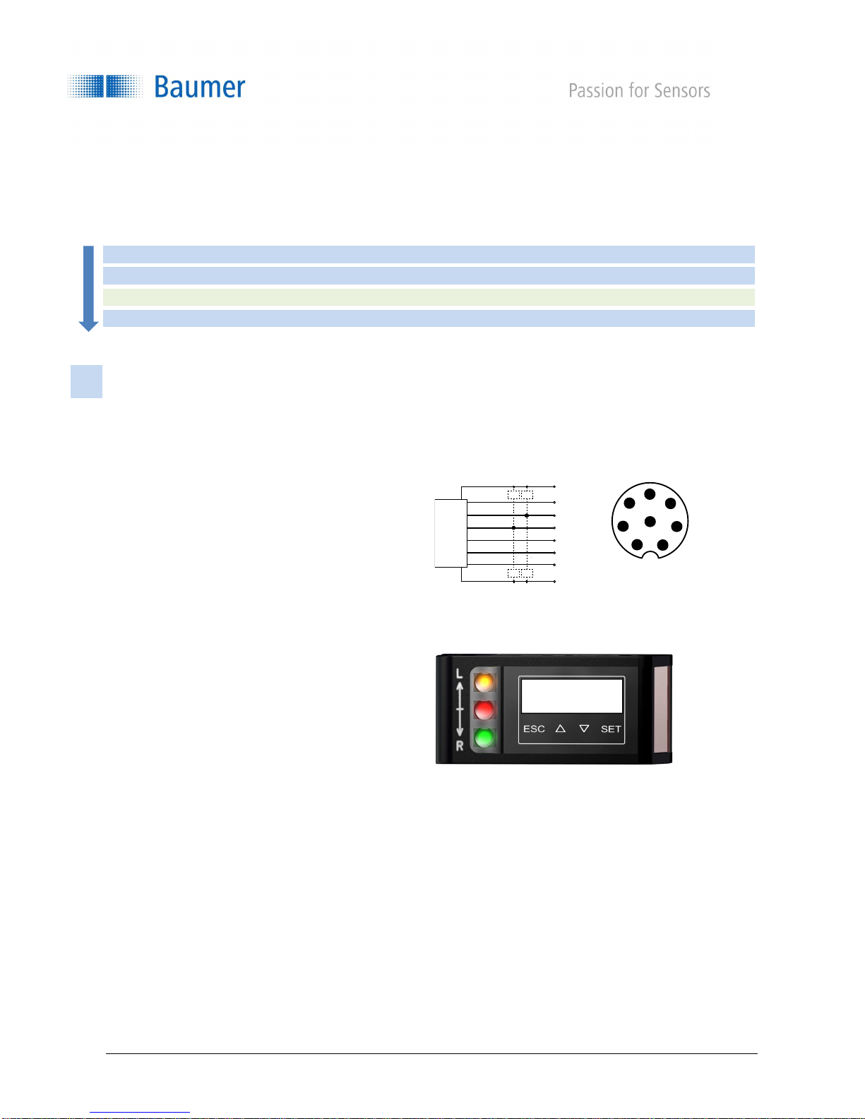
Connect the sensor according to the connection
diagram. A shielded connection cable (8-pole M12)
must be used.
When everything is correctly connected, the sensor
starts up.
ESC = Back
ESC 2 sec. = Run mode
UP = Up/increase value
DOWN = Down/decrease value
SET = OK
SET 2 sec. = Save value
Slide over all 4 keys:
----> = Enables the panel if locked
<---- = Jump to run mode
Setting the language
The language is selected and confirmed by pressing
SET for 2 seconds.
GN
YE
GY
RS 485
push-
PK
pull
RD
BU
English
Deutsch
Italiano
Français
Z Z
(3)
(4)
(5)
(1)WH
(6)
(8)
Z Z
(7)
+Vs
analog
out
alarm
sync in
0V
English
5
6
7
1
4
8
3
2
en_BA_OM70_point_line.docx 5/64 Baumer Electric AG
6/6/2018 8:28 AM/tof V2.0 ANW_81250853 Frauenfeld, Switzerland
Page 6
Let's get started
2
4
3
Installation
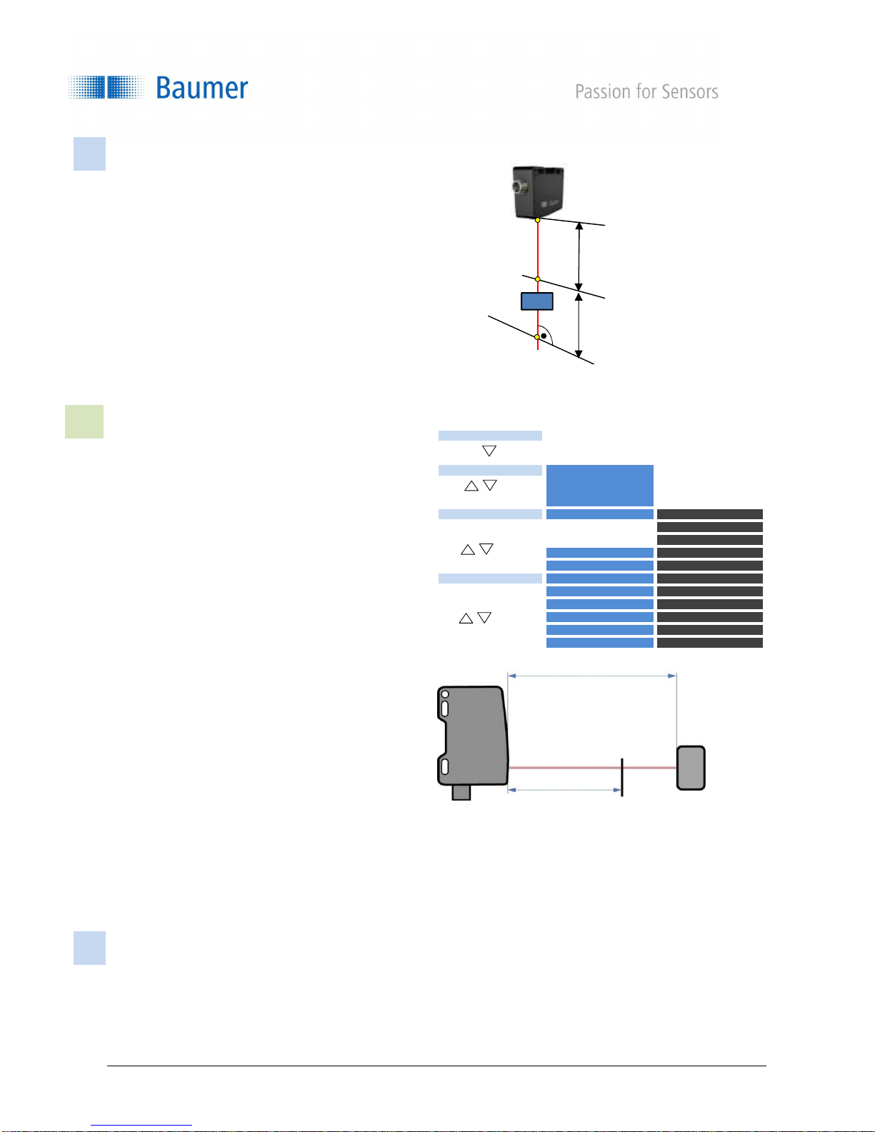
For standard applications, the sensor is mounted and
aligned at right angles to the measuring axis. See
Alignment Chapter.
The object must be within the measuring range Mr,
i.e. between the start of the measuring range Sdc,
and the end of the measuring range Sde.
Object
Sensor reference
point
Blind region
Start of
measuring range
Measuring range
Mr
End of
measuring range
Application-specific settings
The sensor indicates the distance to the object,
measured from the front surface.
Precision (filter)
To achieve better resolution, it is possible to
alternate between Standard, High, Very High and
Highest by filtering the output values.
Analog Out
With SCALE OUT, the start of measuring range Sdc
and the end of measuring range Sde can be
changed, thus optimizing resolution and linearity of
the analog output. 0V or 4 mA apply for the start of
measuring range Sdc, and 10V or 20 mA apply for
the point at the end of measuring range Sde. The
voltage or current output is also selected under
ANALOG OUT. The characteristic curve can also be
inverted under CHARACTERISTIC.
Digital output (switching point)
The sensor is equipped with a switching output that
can be configured either as a THRESHOLD or as a
WINDOW using the DIGITAL OUT function.
Threshold: As soon as the measured value exceeds
the specified threshold, the switching output is
switched.
Window: As soon as the measured value is outside
the specified window, the switching output is
switched. The output level can also be inverted and
the hysteresis set here.
The sensor continuously shows the measured value in mm on the display and transmits it to the controller
through the analog output. Alternatively, the measuring value can also be retrieved from the RS-485
interface.
LIVE MONITOR
PRECISON Standard
ANALOG OUT SCALE OUT DIST NEAR
DIGITAL OUT DIGITAL OUT Point / Window
High
Very High
Highest
DIST FAR
ANALOG OUT Current / Voltage
CHARACTERISTIC Pos. slope / Neg. slope
SWITCH POINT Value in mm
WINDOW P1 Value in mm
WINDOW P2 Value in mm
OUTPUT LEVEL Active high / Active low
HYSTERESIS Value in mm
SET MAX VALUES
Distance in mm /
mA / V
Switching point
(optional)
en_BA_OM70_point_line.docx 6/64 Baumer Electric AG
6/6/2018 8:28 AM/tof V2.0 ANW_81250853 Frauenfeld, Switzerland
Page 7
3 Mounting and connections
ATTENTION!
Connection, installation and commissioning may only be performed by qualified
personnel. Protect optical surfaces from moisture and dirt.
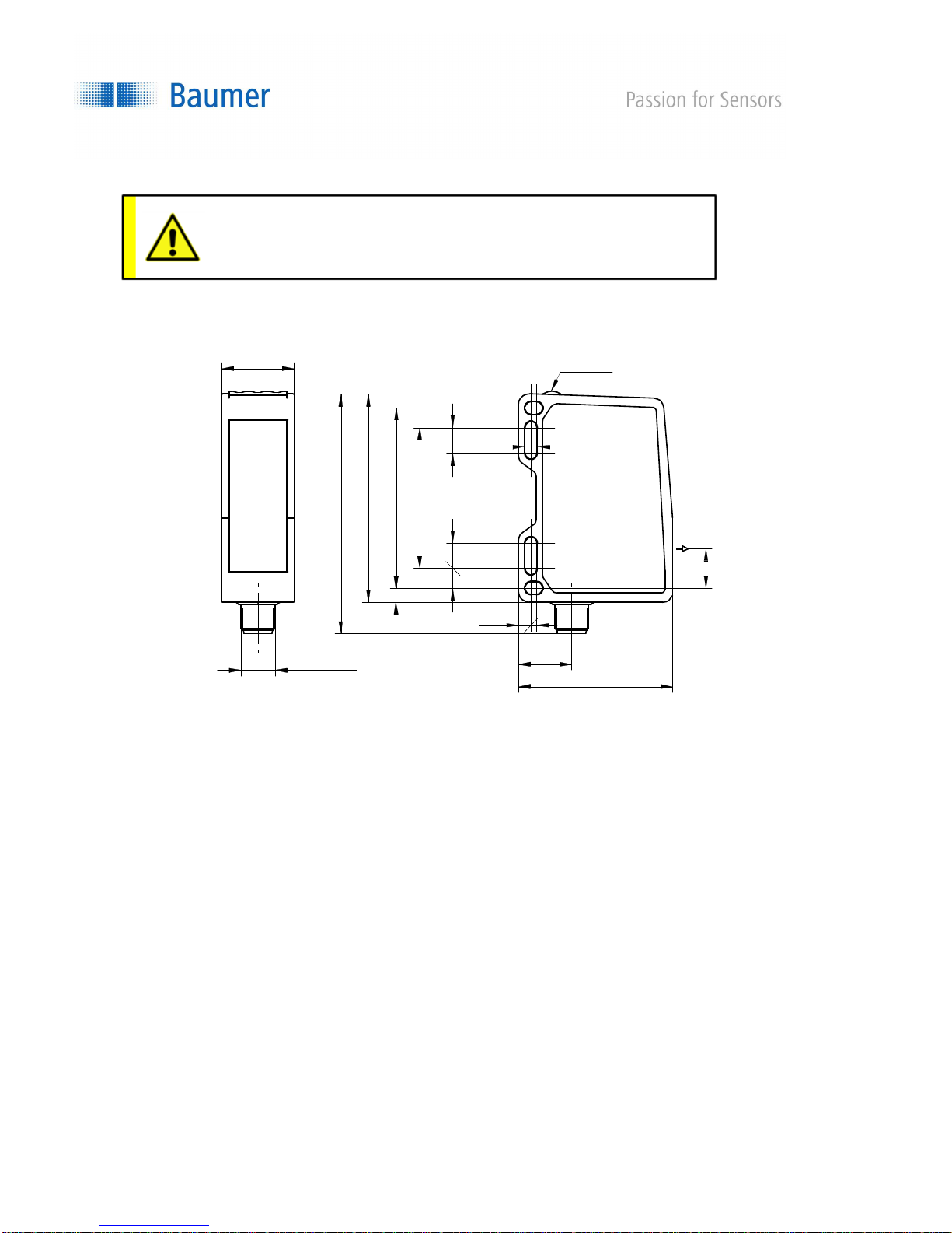
3.1 Dimensions
*Optical axis
26
M12 x 1
LED
4,3
9
74
64
50
85
9
7
14
5
4,5 2
19
55
en_BA_OM70_point_line.docx 7/64 Baumer Electric AG
6/6/2018 8:28 AM/tof V2.0 ANW_81250853 Frauenfeld, Switzerland
Page 8
19 mm
beam
3.1 Sensor reference levels
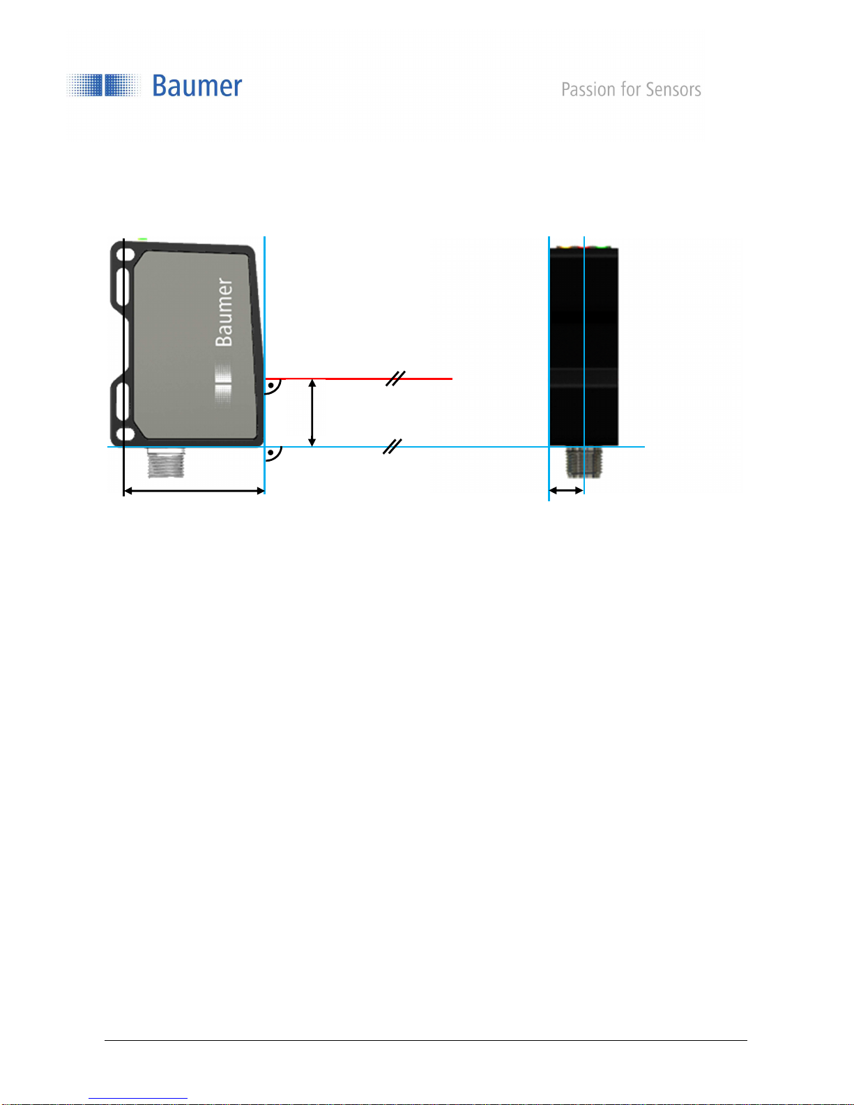
The sensor can be aligned by the following surfaces:
The laser beam of the sensor runs parallel ( // ) to level R3 and is at a right angle to levels R1 and R2. Levels
R1, R2, and R3 serve as a reference for sensor alignment during installation.
Laser
Level R3
50.5 mm
Level R2
Level R1
13 mm
en_BA_OM70_point_line.docx 8/64 Baumer Electric AG
6/6/2018 8:28 AM/tof V2.0 ANW_81250853 Frauenfeld, Switzerland
Page 9
3.2 Definition of the measuring range
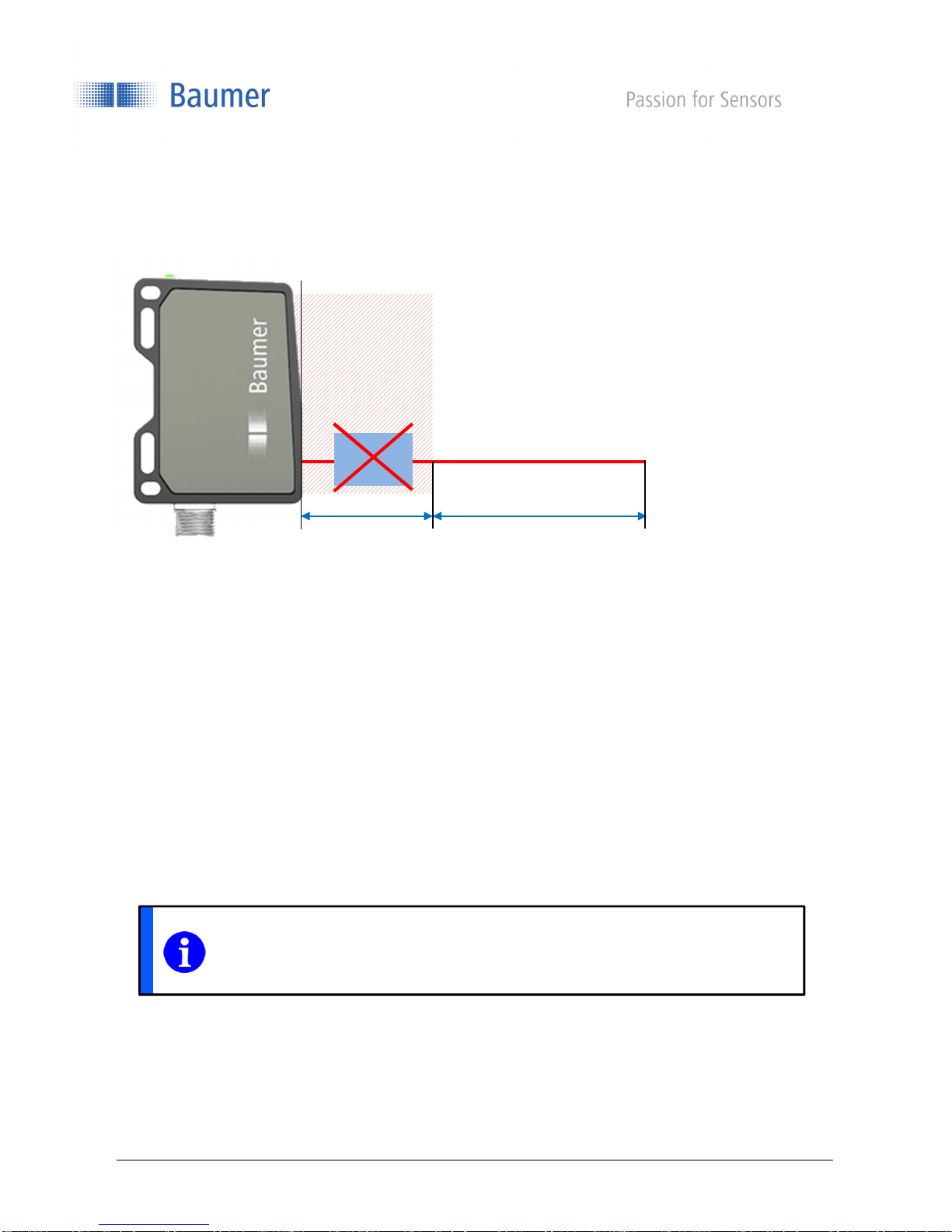
The sensor measures distances within the measuring range. The important definitions are described in the
following figure. The reference level R2 applies as a reference for 0.
R2
Object
Blind region
Measuring range Mr
Start of measuring
range Sdc
End of measuring
range Sde
3.2.1 Blind region
The area from the reference level R2 up to the start of measuring range Sdc is called the blind region, the
sensor cannot detect any objects there.
If there are any objects in this region, this can lead to incorrect measured values.
NOTE
See chapter ANALOG OUT for further information on the analog output.
en_BA_OM70_point_line.docx 9/64 Baumer Electric AG
6/6/2018 8:28 AM/tof V2.0 ANW_81250853 Frauenfeld, Switzerland
Page 10
Prohibited area for
obstacles
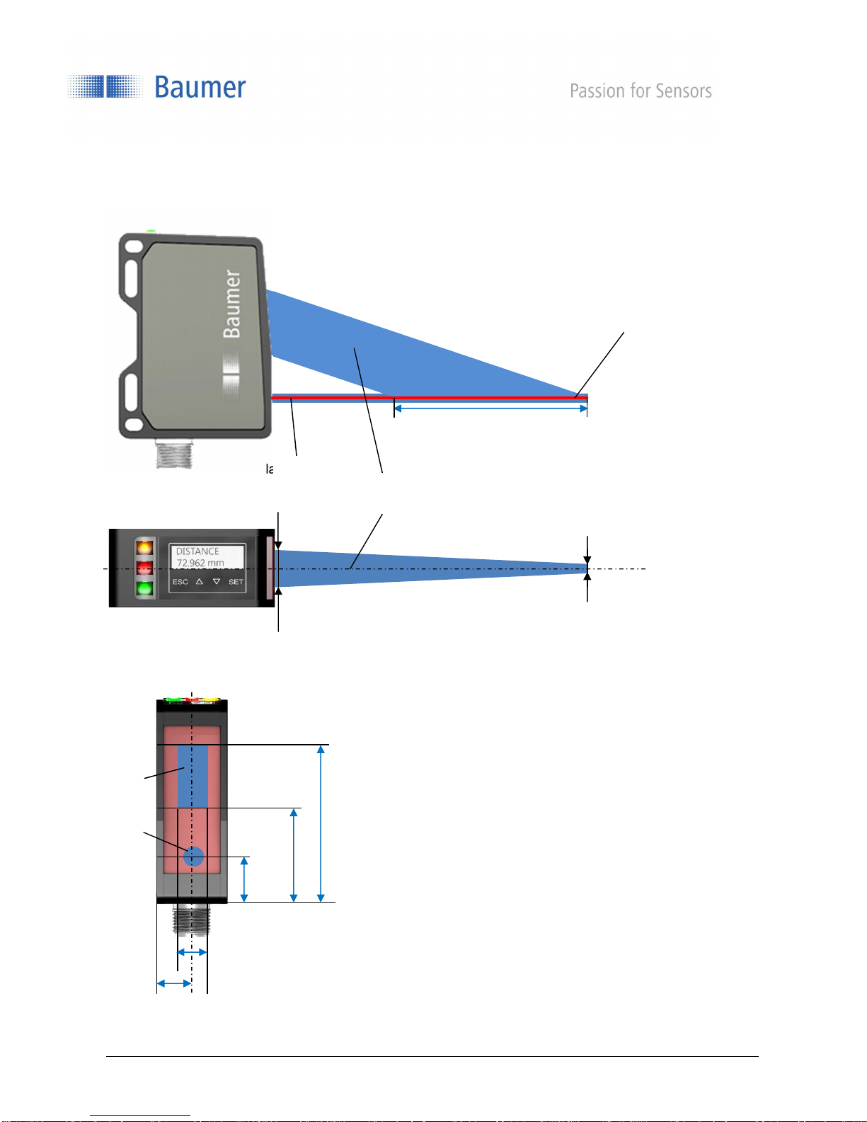
3.2.2 Transmitter and receiver axis
The transmitter and receiver axes must not be covered by obstacles, since this could adversely affect precise
measurements.
Transmitter axis
laser beam
Measuring range Mr
Start of measuring
range Sdc
Receiver axis:
Prohibited area for
obstacles
End of measuring
range Sde
13 mm
19 mm
14 mm
Receiver: Width 14 mm
around the central axis
of the sensor
Dimensions L1 and L2, see
receiver position according to
Sensor Data Sheet chapter.
L1
L2
Max. laser beam diameter (see
data sheet)
en_BA_OM70_point_line.docx 10/64 Baumer Electric AG
6/6/2018 8:28 AM/tof V2.0 ANW_81250853 Frauenfeld, Switzerland
Page 11
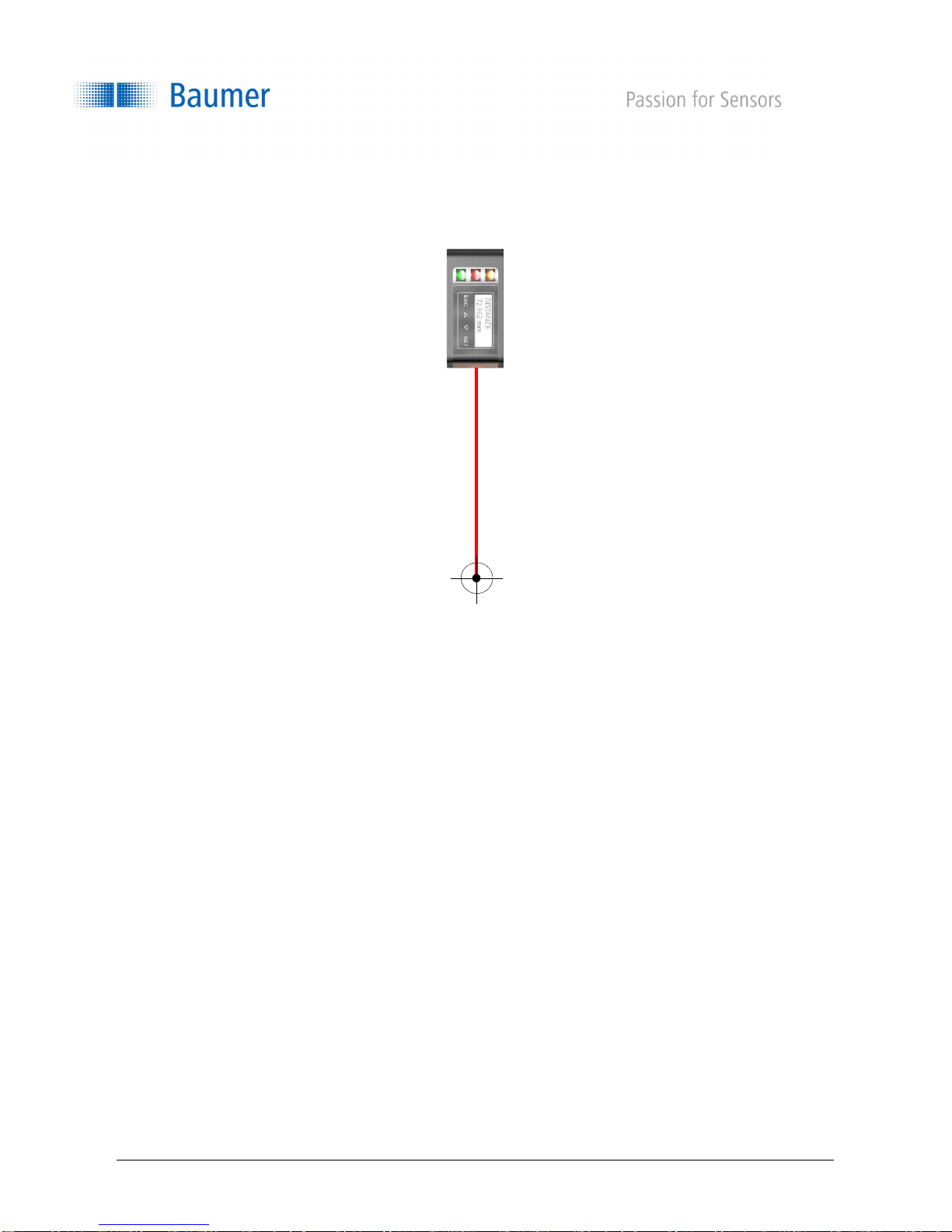
3.2.3 qTarget
The field of view is aligned with the housing reference surfaces at the factory. The beam position is in the
same place for every sensor, which simplifies planning and sensor replacement.
en_BA_OM70_point_line.docx 11/64 Baumer Electric AG
6/6/2018 8:28 AM/tof V2.0 ANW_81250853 Frauenfeld, Switzerland
Page 12
66 mm
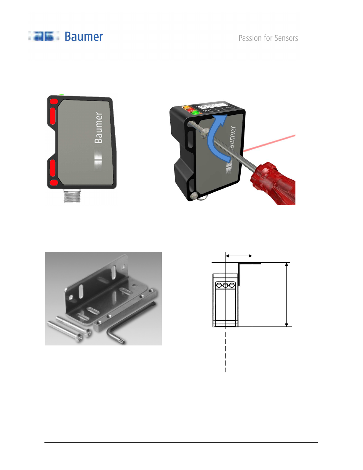
3.3 Mounting
The sensor has four mounting holes for flexible alignment and mounting. The use of 2 M4x35 screws as well
as suitable washers is recommended for mounting. The tightening torque is max. 1.2 Nm.
Tightening torque
max. = 1.2 Nm
3.3.1 Mounting kit for standard installation Order no. 11120705
With the mounting bracket for standard installation, the sensor can be mounted quickly and easily at a 90°
angle to the reference surface.
28.5 mm
Mounting kit 11120705
Contents of this set:
- 90° mounting bracket
- Threaded plate
- 2x spherical head screw M4x35 Torx
- 1x Torx tool T20
en_BA_OM70_point_line.docx 12/64 Baumer Electric AG
6/6/2018 8:28 AM/tof V2.0 ANW_81250853 Frauenfeld, Switzerland
Page 13
3.4 Alignment
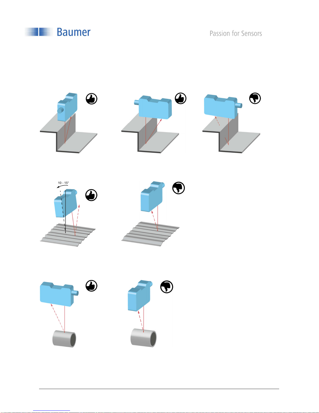
To achieve as reliable and exact measured values as possible, the following hints and tips for mounting should
be followed.
3.4.1 Steps / edges
If measurements are carried out directly beside steps/edges, make sure that the reception beam is not
covered by the step/edge. The same applies when the depth of holes and cracks is measured.
3.4.2 Shiny surfaces
With shiny surfaces, it is important to ensure that the direct reflection does not strike the receiver. This can be
prevented by tilting the sensor slightly. To check this, place a sheet of white paper on the disc of the receiver;
the direct reflection can then be seen clearly.
3.4.3 Round, shiny surfaces
With round, shiny surfaces, the sensor should be aligned in the same axis as the round object in order to
avoid reflections.
en_BA_OM70_point_line.docx 13/64 Baumer Electric AG
6/6/2018 8:28 AM/tof V2.0 ANW_81250853 Frauenfeld, Switzerland
Page 14
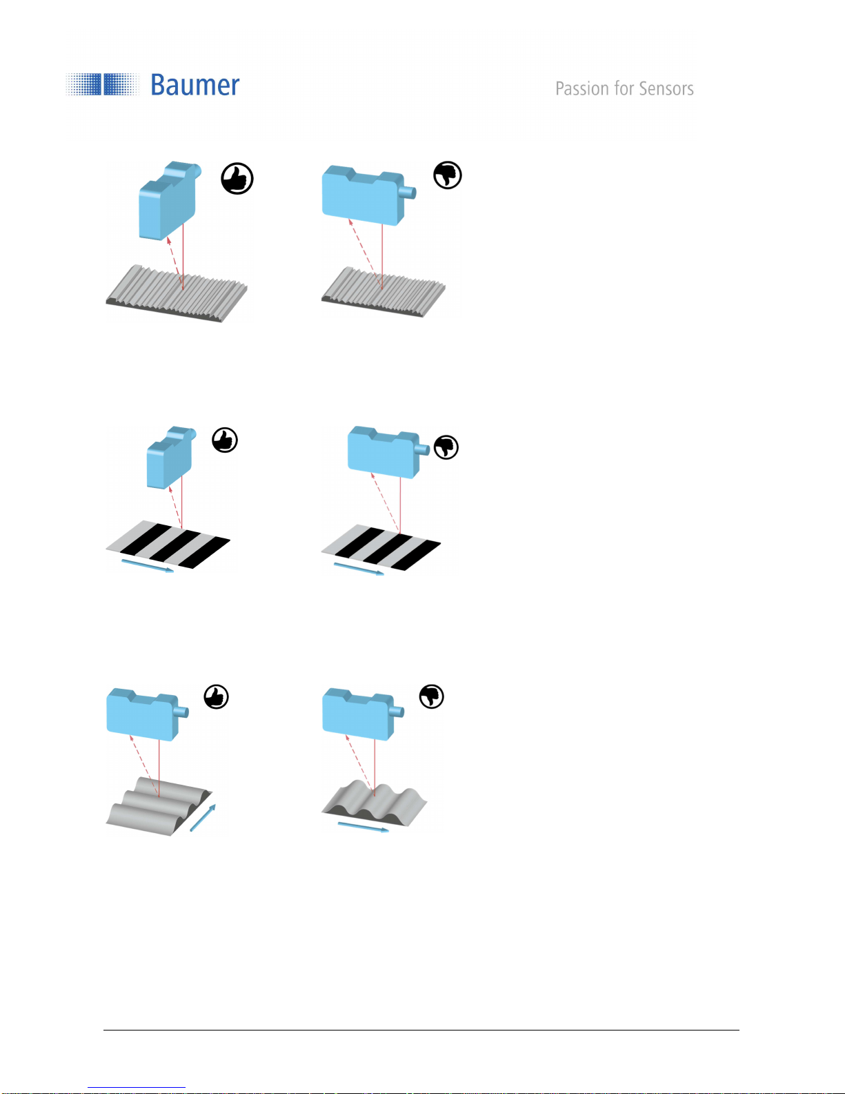
3.4.4 Shiny objects with evenly aligned structure
Particularly with shiny objects, for example turned parts, ground surfaces, extruded surfaces and the like, the
installation position affects the measuring result.
3.4.5 Objects with evenly aligned colored edges
In the correct orientation, the influence on the measuring accuracy is low. In the wrong orientation, the
deviations depend on the differences in reflectivity of the various colors.
3.4.6 Moving objects
If the contour of an object is measured, it is important to ensure that the object moves at right angles to the
sensor, to avoid shadowing and reflections on the receiver.
en_BA_OM70_point_line.docx 14/64 Baumer Electric AG
6/6/2018 8:28 AM/tof V2.0 ANW_81250853 Frauenfeld, Switzerland
Page 15
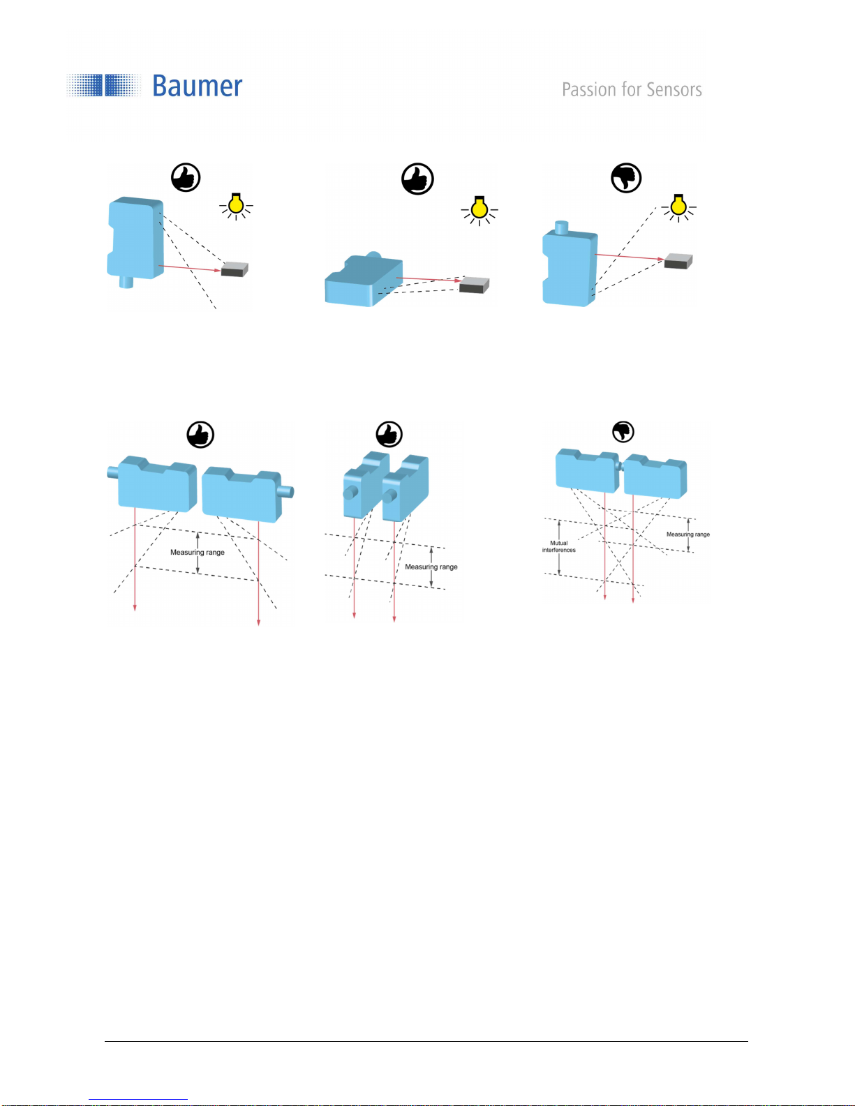
3.4.7 Protection from ambient light
When installing optical sensors, it is important to ensure that there is no strong ambient light in the area of
detection of the receiver.
3.4.8 Reciprocal influence
If several optical sensors are used, they may mutually influence one another. During installation, ensure that
only the sensor's own laser spot is in the detection range of the receiver. Up to a measuring range of 600 mm,
the sensors can be lined up in a row without them influencing each other (picture in the middle).
If the mutual interference cannot be avoided through installation, the sensors can be operated asynchronously
using the Sync-In input, see chapter TRIGGER MODE.
en_BA_OM70_point_line.docx 15/64 Baumer Electric AG
6/6/2018 8:28 AM/tof V2.0 ANW_81250853 Frauenfeld, Switzerland
Page 16
3.5 Connection
Rx/Tx+
Rx/Tx-
(2)
BN
Color Function
Description
ATTENTION!
Incorrect supply voltage will destroy the device!
ATTENTION!
Connection, installation and commissioning may only be performed by qualified
personnel.
ATTENTION!
The IP protection class is valid only if all connections are connected as
described in the technical documentation.
ATTENTION!
Products with laser class 1 laser beams in accordance with EN 60825-1:2014
can be operated safely without additional safety precautions. Nevertheless
direct contact between the eye and beam should be avoided.
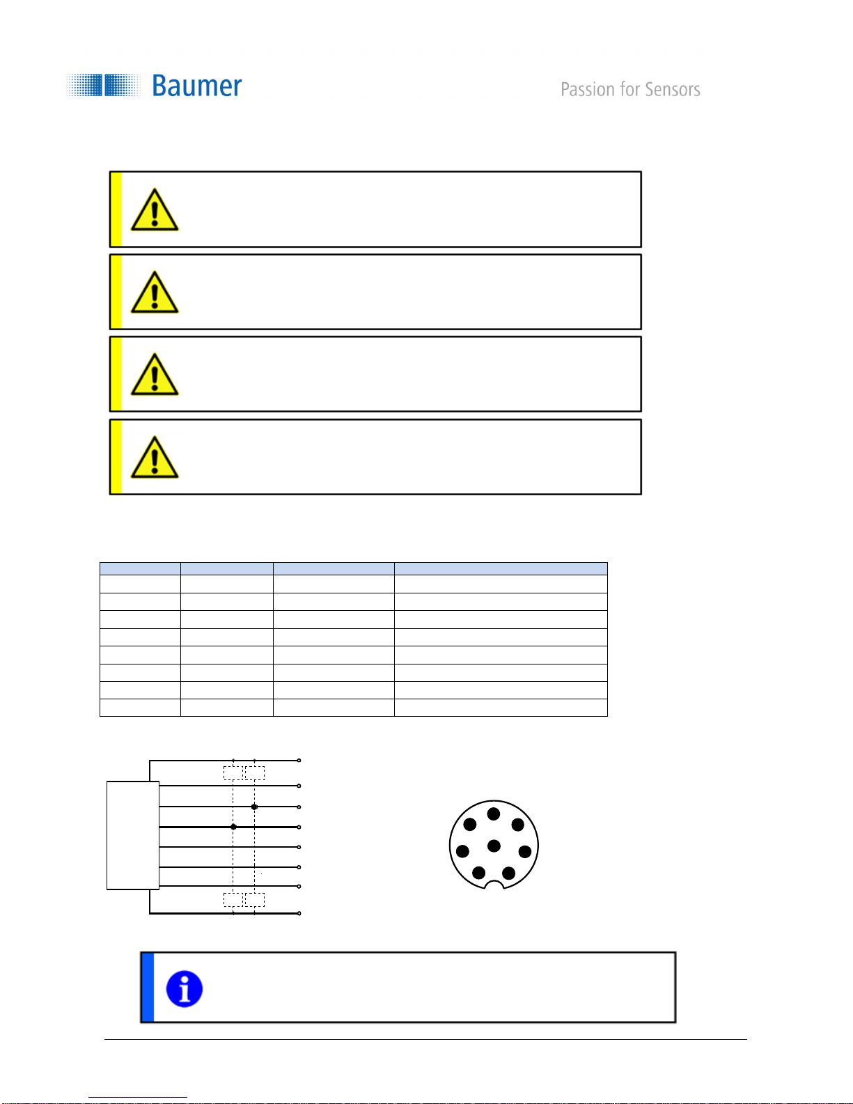
3.5.1 Pin assignment and connection diagram
Pin 1
Pin 2
Pin 3
Pin 4
Pin 5
Pin 6
Pin 7
Pin 8
RS 485
push-
pull
WH = white Rx/Tx- RS 485 receive/transmit- (B)
BN = brown + Vs Voltage supply (+15…+28 VDC)
GN = green analog Analog output (4…20 mA or 0…10V)
YE = yellow out Switching output, push-pull
GY = gray alarm Alarm output, push-pull
PK = pink Rx/Tx+ RS-485 receive/transmit+ (A)
BU = blue 0V Ground GND
RD = red sync in Input synchronization
+Vs
Z Z
(3)
GN
YE
GY
WH
PK
RD
BU
(4)
(5)
(6)
(8)
(7)
(1)
Z Z
NOTE
We recommend that you connect unused cables to GND (0V).
analog
out
alarm
sync in
0V
5
6
8
7
1
2
Top view of plug
4
3
en_BA_OM70_point_line.docx 16/64 Baumer Electric AG
6/6/2018 8:28 AM/tof V2.0 ANW_81250853 Frauenfeld, Switzerland
Page 17

3.5.2 Connection cable
An 8-pole, shielded connection cable (connector) is required.
Baumer connection cables with the following order codes are recommended:
• 10127844 ESG 34FH0200G (length 2 m, straight plug)
• 11053961 ESW 33FH0200G (length 2 m, angled plug)
• 10129333 ESG 34FH1000G (length10 m, straight plug)
• 10170054 ESW 33FH1000G (length 10 m, angled plug)
Other cable lengths are available.
When the analog output is used, the cable length affects signal noise. Signal noise increases the longer the
connection cable is.
Analog output I_OUT
Noise: 5.92 µA (1 sigma) (10m cable and 680 Ohm)
3.59 µA (1 sigma) (2m cable and 680 ohms)
Analog output U_OUT
Noise: 4.80 mV (1 sigma) (10m cable and 100 kOhm)
3.03 mV (1 sigma) (2m cable and 100 kOhm)
We recommend that you use the RS-485 interface for high-precision applications.
en_BA_OM70_point_line.docx 17/64 Baumer Electric AG
6/6/2018 8:28 AM/tof V2.0 ANW_81250853 Frauenfeld, Switzerland
Page 18
4 Configuration
DISTANCE
112,422 mm
PRECISION
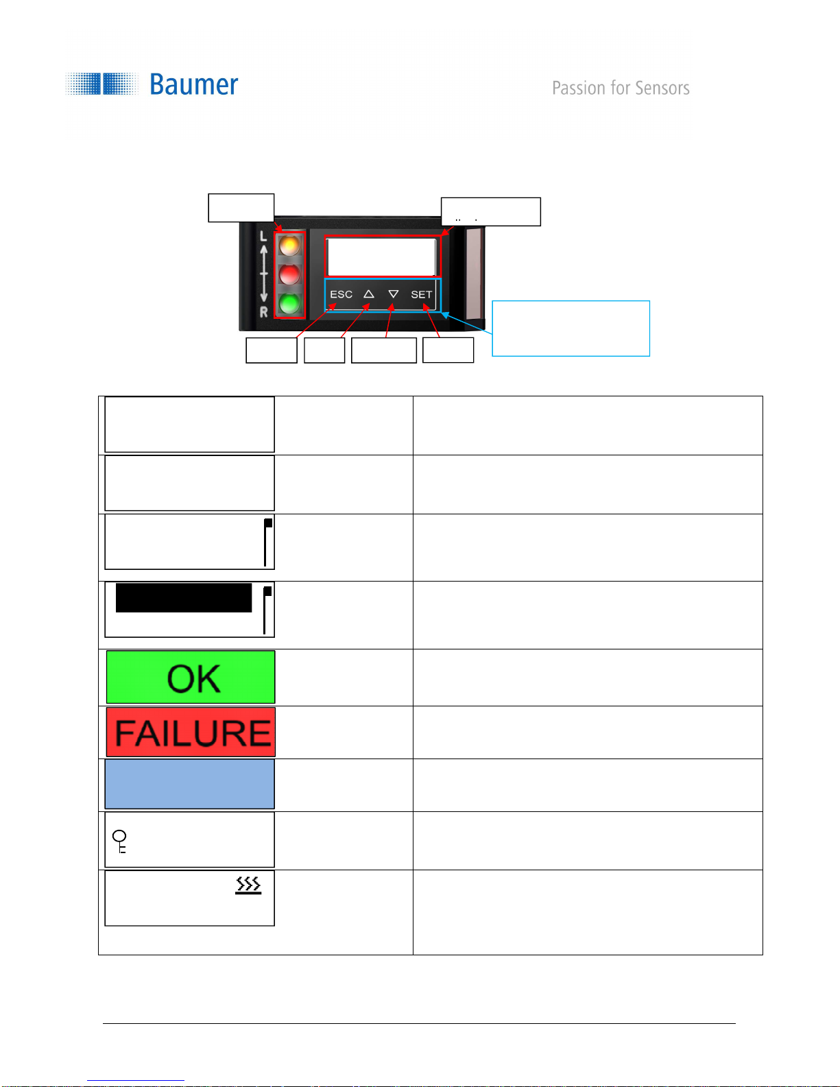
4.1 Overview of control elements
4.1.1 Display modes
112,422 mm
DISTANCE
112,422 mm
PRECISION
STANDARD
VERY HIGH
112,422 mm
LEDs
ESC UP DOWN
Graphical
SET
Run mode
The sensor is in run mode, the measuring value is
displayed in large characters.
Main menu
In the main menu the active mode is displayed at the top,
and the measuring value is displayed at the bottom.
Scroll bar
The square on the right indicates the position within the
current menu. The next menu item can be accessed using
the arrow keys.
Change value
If the function/mode at the top is highlighted in black, the
value of the lower line can be adjusted using the
UP/DOWN keys and saved with SET (hold).
Process successful
The display background lights up green: Value
successfully saved
Error
The display background lights up red: Error during the
save process or wrong value entered.
Setting mode
As soon as the sensor is in setup mode, the display
background lights up blue.
Keys locked
If this symbol is on the left side of the screen, the four
pushbuttons are locked for operation.
Touch panel: Four
touch-sensitive keys
DISTANCE
112,422 mm
en_BA_OM70_point_line.docx 18/64 Baumer Electric AG
6/6/2018 8:28 AM/tof V2.0 ANW_81250853 Frauenfeld, Switzerland
Warming up
The warm-up sign appears in the top right of the display.
The sensor is not yet in thermal equilibrium; optimum
measurement performance is reached after the symbol
disappears.
Page 19
4.1.2 Functions of the individual keys
Key Pressed briefly Pressed >2 s.
ESC Back Jump to run mode
UP Up/increase value
DOWN Down/decrease value
SET OK/submenu/next entry** Save new value*
*Only in setup mode menu when the top line is highlighted in black (change value)
**When entering strings of numbers, use OK to jump to the right. Once the end is reached, the cursor jumps
back to the left to the beginning
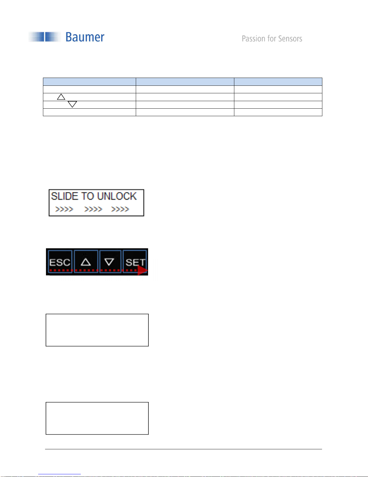
4.1.3 Locking the touch panel
The keys on the control panel are locked when they are not pressed for 5 minutes. A key symbol appears, and
the measuring value is displayed in large lettering.
When it is pressed, the following text appears:
To re-enable the touch panel, it is required to quickly slide a finger over all four keys from left to right (slide
over ESC, UP, DOWN, and SET).
When controlled via RS-485:
When the sensor is controlled using RS-485, it cannot be operated with the display at the same time. The
keys are disabled. When the keys are pressed, the following text appears on the display:
RS-485 controls
the sensor
Disconnect briefly from the power supply or use an RS-485 command to enable the display and operate the
sensor using the display.
Locking via RS-485 command:
The sensor keys can be permanently locked with a RS-485 command. This locking remains activated even if
the senor is no longer controlled via RS-485. The keys must be unlocked with a RS-485 command. When the
locked keys are touched, the following text appears on the display:
RS-485 locks
the touch keys
en_BA_OM70_point_line.docx 19/64 Baumer Electric AG
6/6/2018 8:28 AM/tof V2.0 ANW_81250853 Frauenfeld, Switzerland
Page 20
4.1.4 Further key functions
Action
Reaction
Unlock locked touch panel
Jump directly to run mode
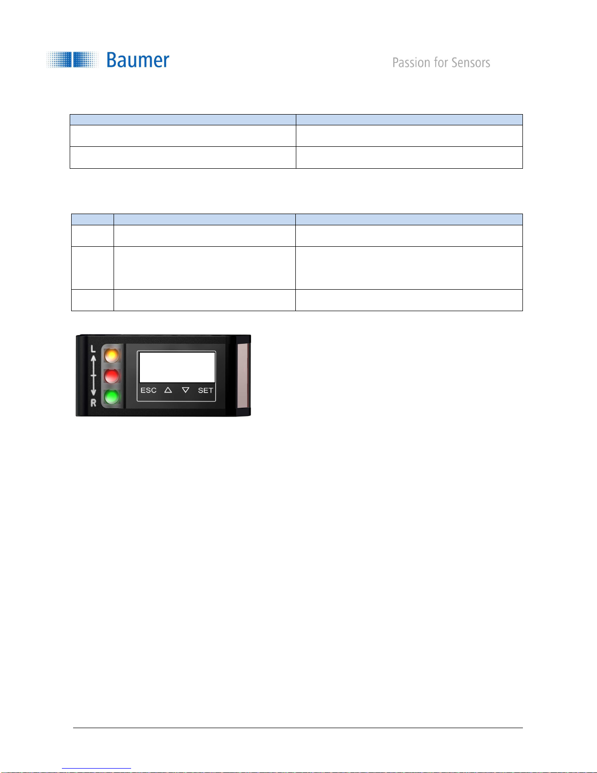
LED Lights up
Flashes
Yellow
out1 activated
Red out2 activated
Insufficient excess gain
Green
Supply voltage
Short circuit
Slide over all keys from left to right
Slide over all keys from right to left
4.1.5 LEDs on the sensor
Switching output1 active
Only if touch panel is locked
Can be used from any menu
-
Alarm output active. No measuring object
within the field of measurement or signal
quality is inadequate.
Sensor ready for operation.
DISTANCE
112,422 mm
Object close to signal reserve or signal quality not
ideal
Check connection at switch or alarm output.
en_BA_OM70_point_line.docx 20/64 Baumer Electric AG
6/6/2018 8:28 AM/tof V2.0 ANW_81250853 Frauenfeld, Switzerland
Page 21
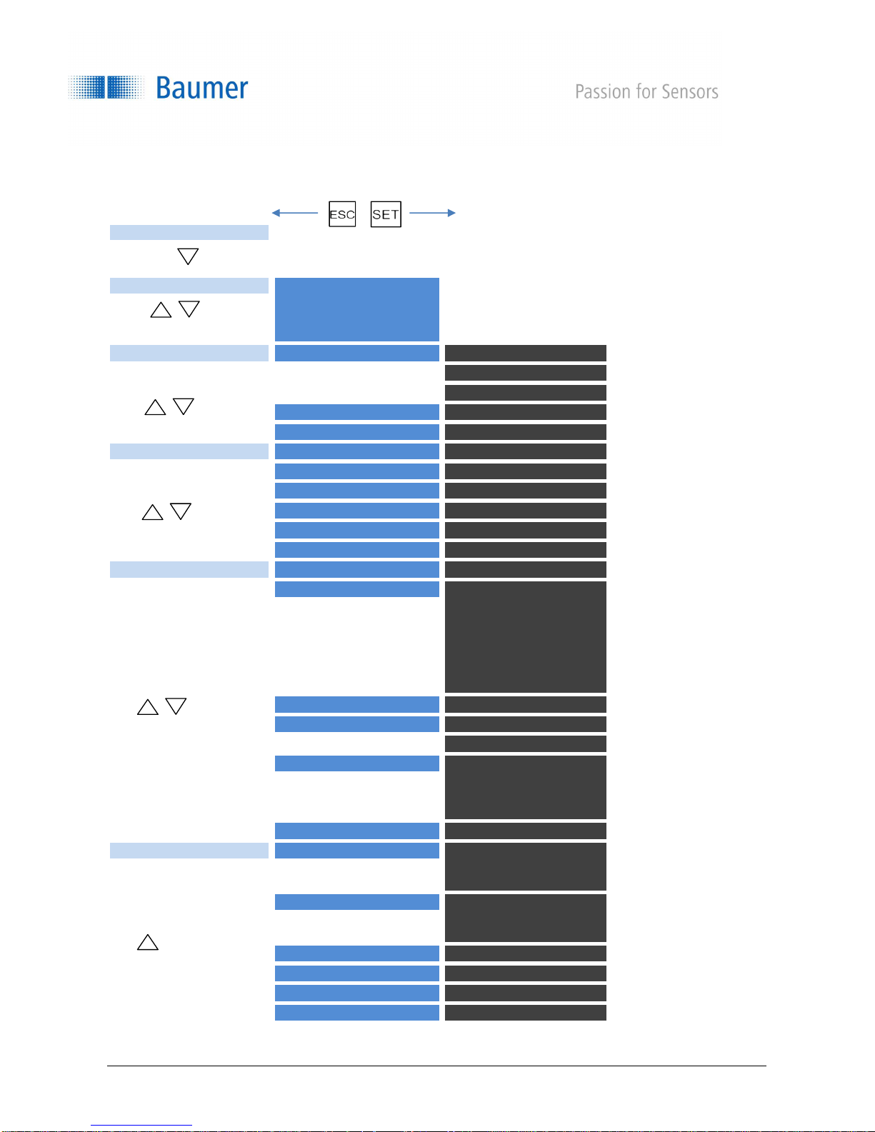
4.2 Function tree
The menu that can be accessed via the touch panel is shown below.
LIVE MONITOR
PRECISON Standard
High
Very High
Highest
ANALOG OUT SCALE OUT DIST NEAR
DIST FAR
SET MAX VALUES
ANALOG OUT Current / Voltage
CHARACTERISTIC Pos. slope / Neg. slope
DIGITAL OUT DIGITAL OUT Point / Window
SWITCH POINT Value in mm
WINDOW P1 Value in mm
WINDOW P2 Value in mm
OUTPUT LEVEL Active high / Active low
HYSTERESIS Value in mm
SYSTEM TRIGGER MODE Continuous/Single shot
RS485 BAUD 38400
57600
115200
230400
460800
921600
1500000
RS485 ADDR number
SENSOR INFO SENSOR TYPE
SERIAL NUM
LANGUAGE English
Deutsch
Inglese
Français
RESET Factory Set
SETTINGS APPLY Setting 1
Setting 2
Setting 3
STORE Setting 1
Setting 2
Setting 3
SHOW ACTIVE Values
SHOW SETTING 1 Values
SHOW SETTING 2 Values
SHOW SETTING 3 Values
en_BA_OM70_point_line.docx 21/64 Baumer Electric AG
6/6/2018 8:28 AM/tof V2.0 ANW_81250853 Frauenfeld, Switzerland
Page 22
4.3 LIVE MONITOR
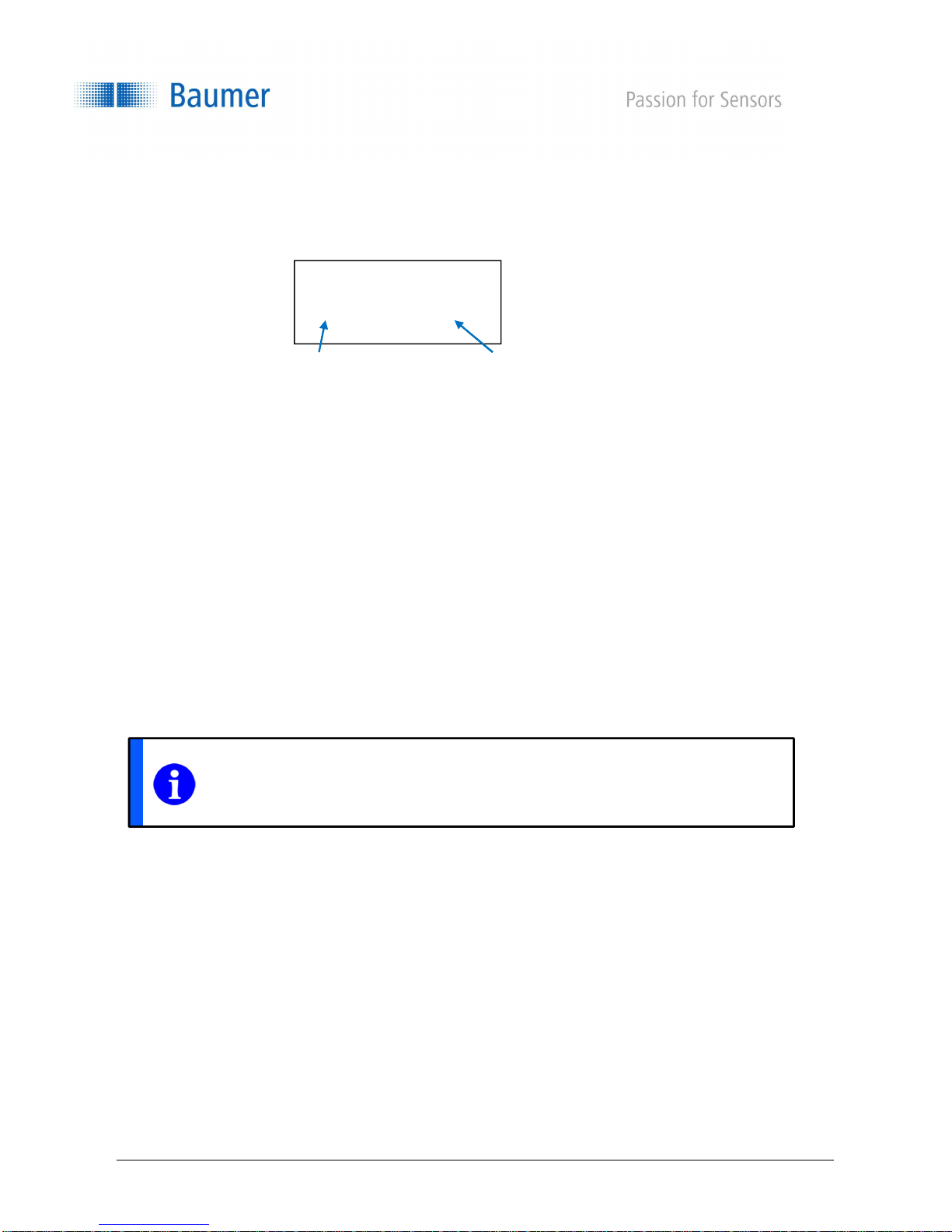
The installation conditions can be checked quickly and easily by displaying the lighting reserve as well as the
measuring frequency.
4.3.1 Lighting reserve
This factor specifies by how many times an object may become darker in order to obtain a valid measurement
nevertheless. For a valid measurement, a minimum of factor 1 is required.
The higher this value is, the shorter the object has to be exposed, which increases the measuring frequency.
Below factor 1, the sensor gets too little light back and does not specify any measured value, the alarm output
is active.
Lighting reserve
LIVE MONITOR
321 2475 Hz
Current
measuring
frequency in
Hz
4.3.2 Measuring frequency in Hz
Displays the current measuring frequency in Hz.
For more information, see the chapter on measuring frequency, measuring repeat time and response time.
NOTE
For the fastest response time as well as maximum exposure reserve, the object should
be as bright as possible (not shiny).
en_BA_OM70_point_line.docx 22/64 Baumer Electric AG
6/6/2018 8:28 AM/tof V2.0 ANW_81250853 Frauenfeld, Switzerland
Page 23
4.4 PRECISION
Activating filtering can reduce noise and thus increase resolution and repeat accuracy. This increases the
response time, but the measuring frequency remains unchanged.
Standard = normal resolution12
High = resolution is approximately twice as high12
Very high = resolution about three times as high12
Highest = resolution about four times as high12
4.4.1 Influences of the PRECISION filter
The higher the precision is set, the more response times and release times increase, which means that the
response time for moving objects slows down. The measuring frequency is not affected by the use of this
filter.
PRECISION works with moving median as well as moving average filters.
Moving median
The median of a finite list is the measurement with the middle measured value of a string of numbers (e.g.
median of {3, 3, 5, 9, 11} is 5). The number of measured values saved in an array is called the number of
measured values, e.g. {3, 3, 5, 9, 11} corresponds to 5 measured values. When a new measured value is
added, the oldest is removed (moving filter). A sudden change in measured values will only lead to a changed
after half of the saved number of measured values (e.g. number of measured values = 5 means that the
measured value at the output is only affected after 3 measured values).
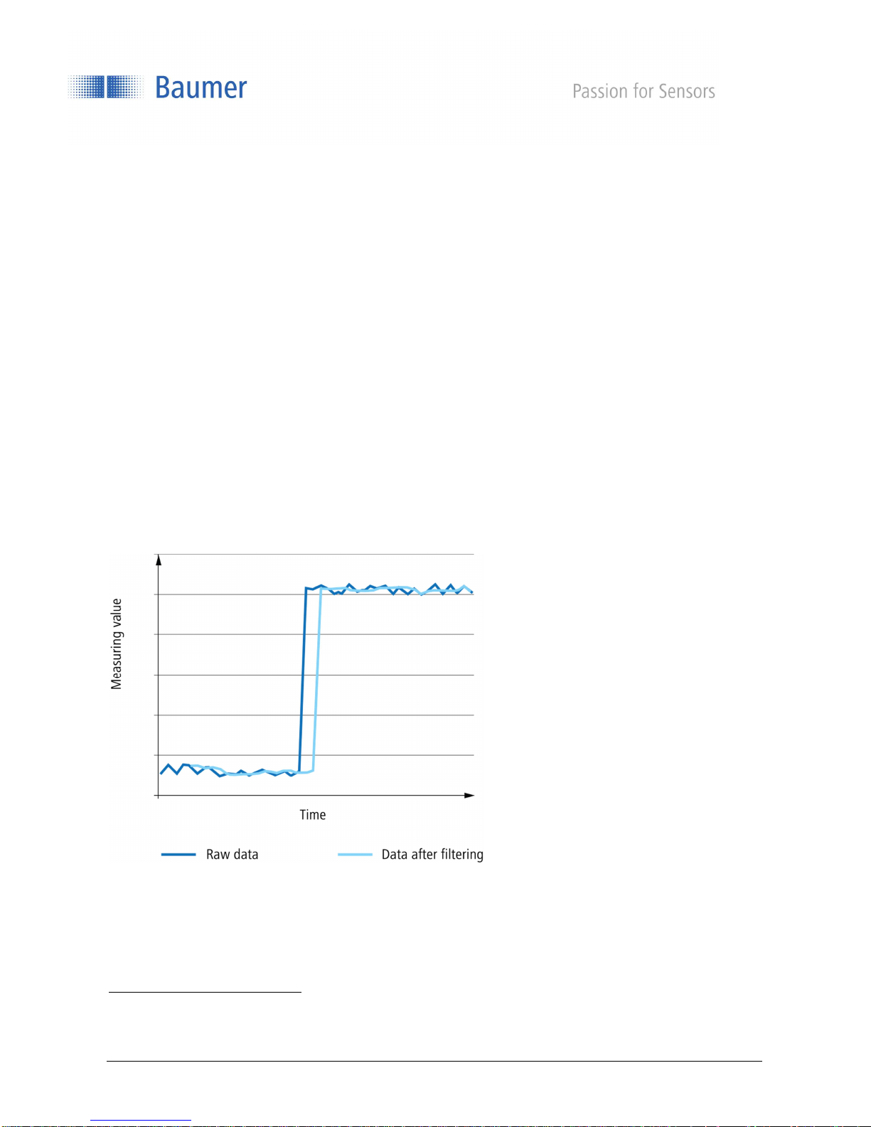
This diagram shows the effects of the median (number of measured values 5). The filter is used to suppress
measurement errors. The output only changes after a defined number of measured values (number of
measured values/2). The measuring frequency is not affected by this filter, but the response time is.
1
In accordance with chapter Sensor Data Sheet
2
Depending on the object to be measured
en_BA_OM70_point_line.docx 23/64 Baumer Electric AG
6/6/2018 8:28 AM/tof V2.0 ANW_81250853 Frauenfeld, Switzerland
Page 24
Moving average
The output value of the moving average filter is the average of the defined number of measured values which
have been saved. When a new measured value is added, the oldest is removed (moving filter).
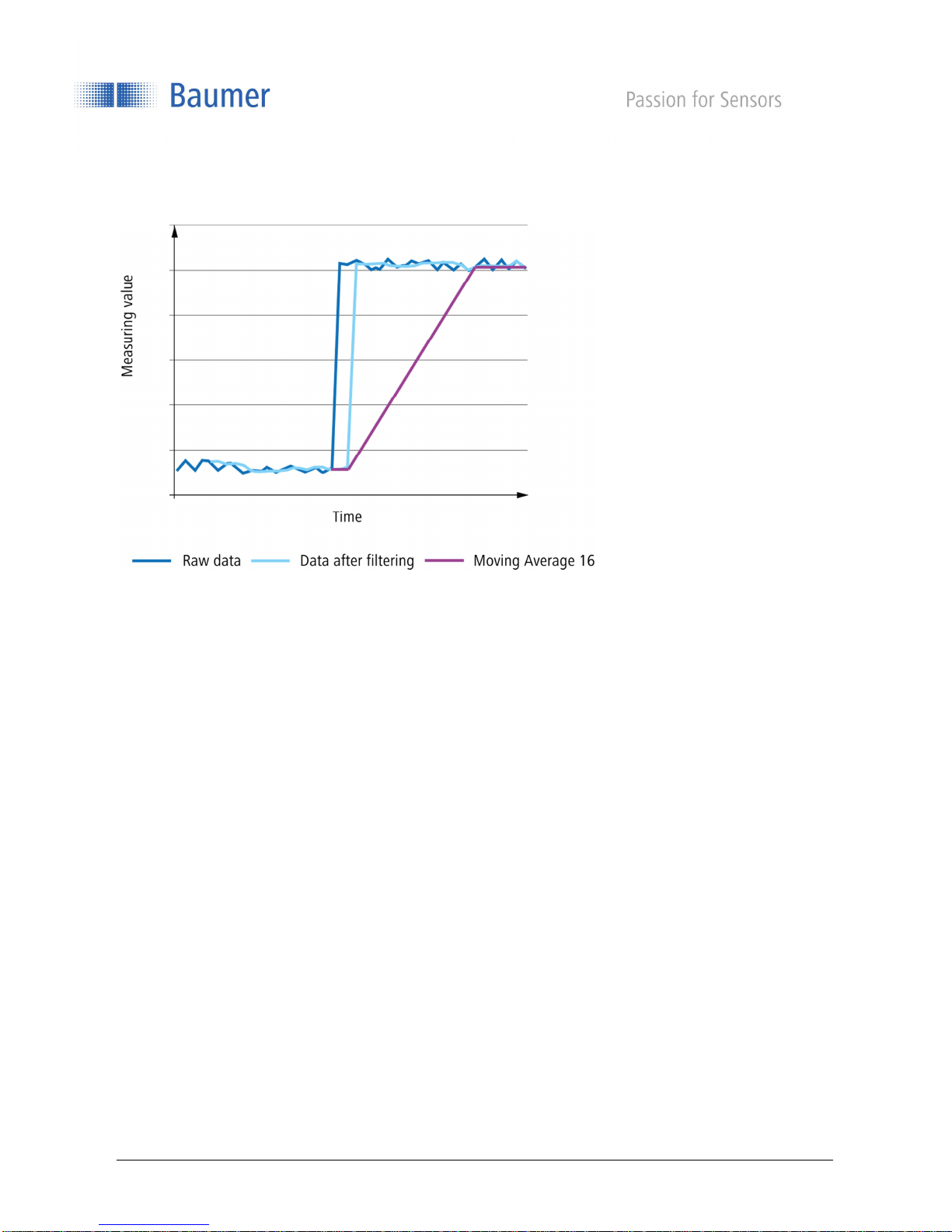
As shown in the diagram, the moving average evens out the output value. In contrast to the median filter, it is
possible that with the moving average, the displayed measured values were never measured as such. The
measuring frequency is not affected by this filter, but the response time is.
Number of measured values required until the correct measured value is displayed:
- In the PRECISION = HIGH mode, the distance must be stable for 4 + 16 measured values before the
correct value is displayed
- In the PRECISION = VERY HIGH mode, the distance must be stable for 8 + 128 measured values
before the correct value is displayed
Example
Calculate the response time with a measurement frequency of 500 Hz, PRECISION = HIGH
1 / 500 Hz = 0.002 s
Median = 7 / 2 (formula: measured value / 2 ) = 4
Average = 16
Response time = 0.002 * (4 + 16) = 0.04 s = 40 ms
en_BA_OM70_point_line.docx 24/64 Baumer Electric AG
6/6/2018 8:28 AM/tof V2.0 ANW_81250853 Frauenfeld, Switzerland
Page 25
Object
4.5 ANALOG OUT
The settings of the analog output are defined here.
The display shows the sensitivity of the analog output in µA/mm or mV/mm (depending on the setting
ANALOG OUT current/voltage). Adjusting the analog calibration curve using DIST NEAR and DIST FAR
changes the displayed sensitivity value of the analog output. This value can be used to convert the analog
signal (µA/mm or mV/mm) into a value in mm or vice versa.
4.5.1 SCALE OUT
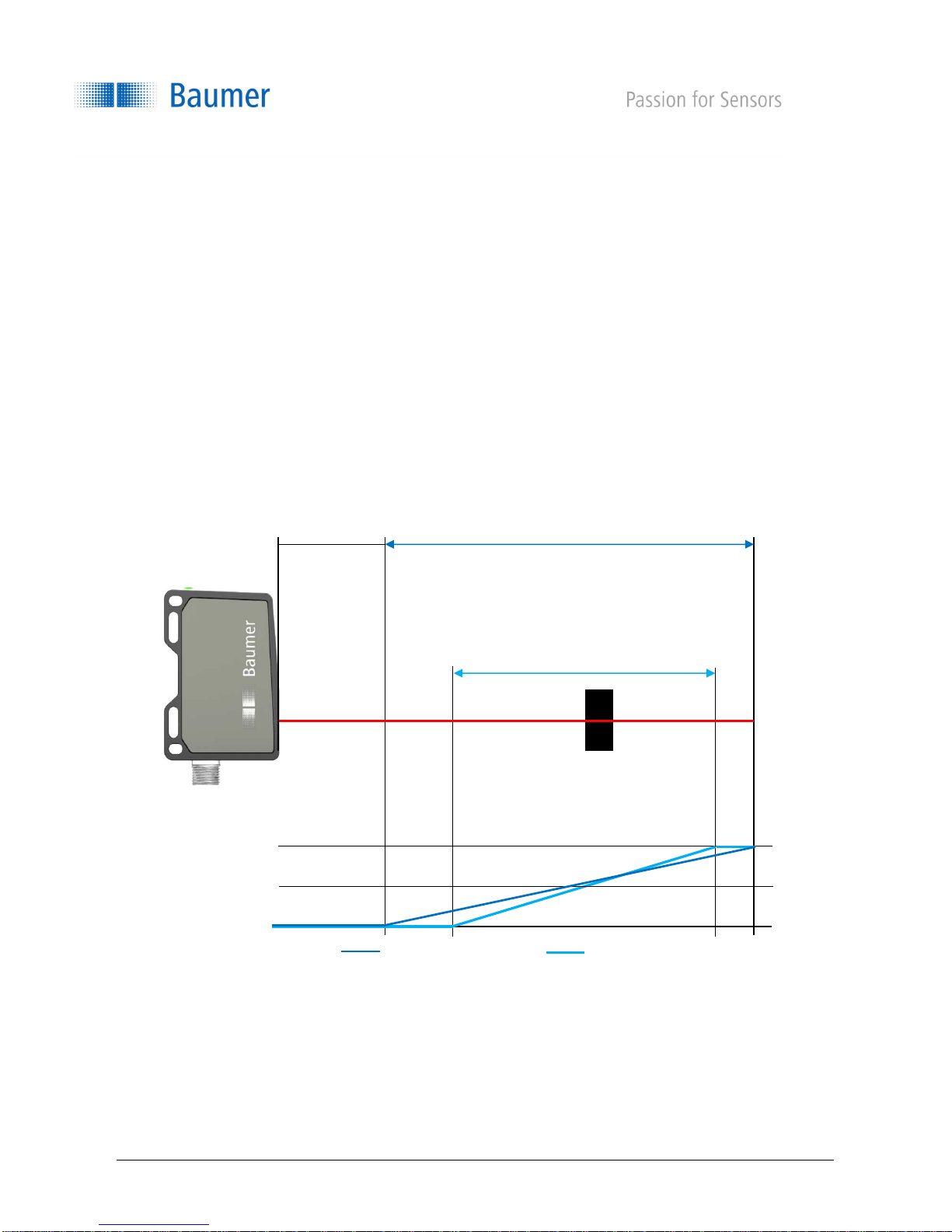
In the factory setting, the analog output runs across the entire measuring range Mr (start of measuring range
Sdc - end of measuring range Sde) from 0...10V (voltage mode) or from 4...20mA (current mode). The start
and end of the measuring range can be reset (taught) with SCALE OUT, reducing the measuring field and
changing the calibration curve. This means that limiting the measuring range to reduced limits can improve the
resolution and linearity of the analog output.
Blind region
20 mA / 10V
12 mA / 5V
4 mA / 0V
Start of measuring
range Sdc
DIST NEAR: Start of
measuring range
Sdc scaled
Standard calibration
curve
End of measuring range
Sde
Measuring range Mr
DIST FAR: End of
measuring range
Sde scaled
Scaled calibration
curve
en_BA_OM70_point_line.docx 25/64 Baumer Electric AG
6/6/2018 8:28 AM/tof V2.0 ANW_81250853 Frauenfeld, Switzerland
Page 26
NOTE
NOTE
4.5.1.1 DIST NEAR
Scaled start of measuring range Sdc in mm for analog output value 4 mA / 0V.
DIST NEAR >= Start of measuring range Sdc
DIST NEAR <= DIST FAR (observe the minimum analog output window size)
4.5.1.2 DIST FAR
Scaled end of measuring range Sde in mm for analog output value 20 mA/10V.
DIST FAR <= End of measuring range Sde
DIST FAR >= DIST NEAR (observe the minimum analog output window size)
4.5.1.3 SET MAX VALUES
SCALE OUT is reset to the standard setting (maximum measuring field) with the "set max values" command.
Example Scaling the measuring range with SCALE OUT
The sensor should display 4 mA at a distance of 110 mm and 20 mA at a distance of 140 mm.
Set DIST NEAR to 110 mm
Set DIST FAR to 140 mm
Through the reduced measuring field, the resolution as well as the linearity of the analog output
are improved, see chapter Sensor Data Sheet.
As soon as the alarm output is active, the analog and switching outputs for 75
measuring cycles are kept at the last valid value. See chapter Alarm Output.
en_BA_OM70_point_line.docx 26/64 Baumer Electric AG
6/6/2018 8:28 AM/tof V2.0 ANW_81250853 Frauenfeld, Switzerland
Page 27
Output signal V/mA
Pos. slope
Neg. slope
range Sdc
End of
measuring
Measured value in mm
4.5.2 ANALOG OUT
The analog output can be reset to voltage (0-10 V ) or current (4-20 mA), depending on the intended purpose.
In order to minimize interference in the wiring, we recommend using the current output.
• Current
• Voltage
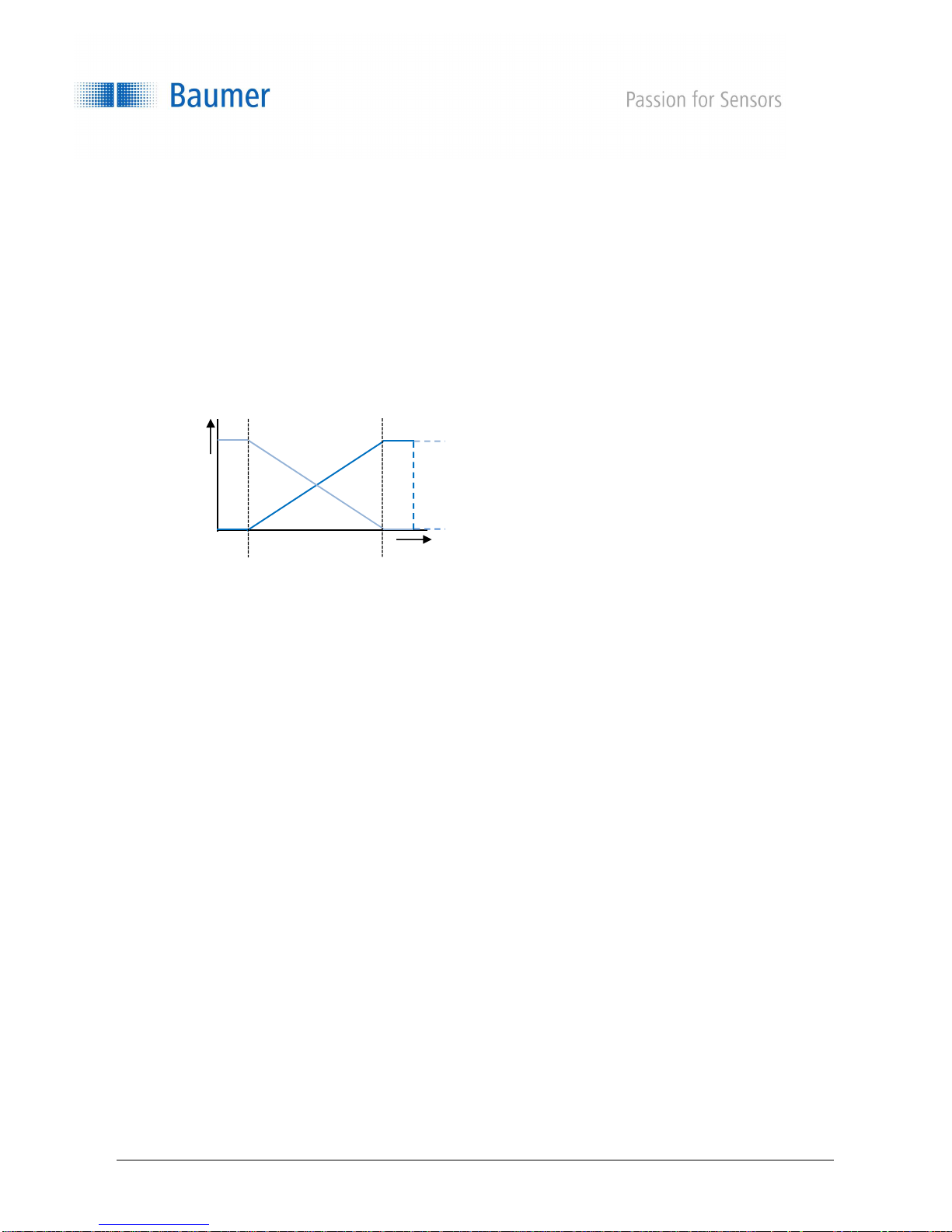
4.5.3 CHARACTER.
The calibration curve can be inverted here. In a positive curve, the output signal increases when the
measured value rises, while the output signal decreases in a negative curve.
Start of measuring
range Sde
en_BA_OM70_point_line.docx 27/64 Baumer Electric AG
6/6/2018 8:28 AM/tof V2.0 ANW_81250853 Frauenfeld, Switzerland
Page 28
Object
4.6 DIGITAL OUT
With Pin 4 (out), the user has a configurable switching output.
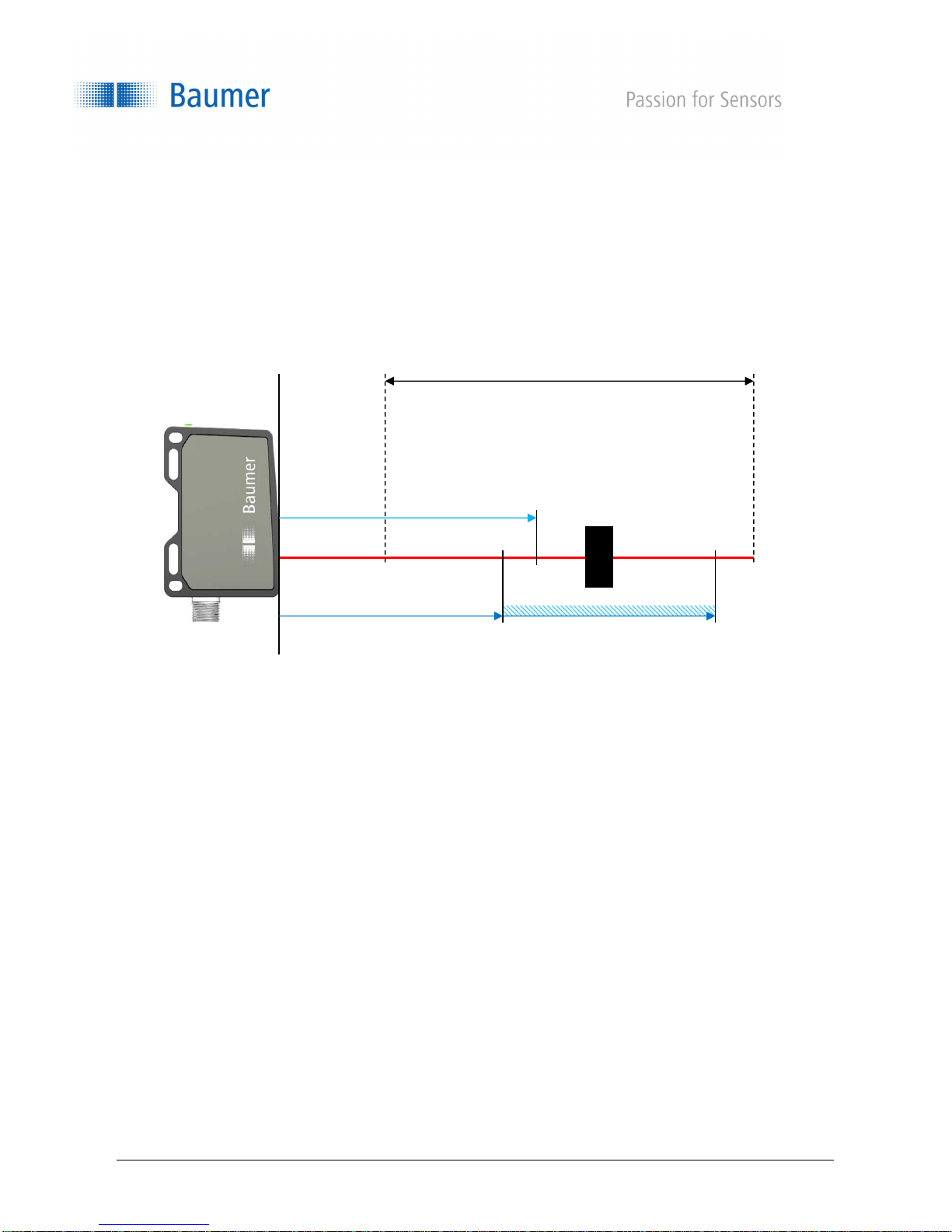
This can be defined as a threshold or as a window. Pin 4 switches as soon as the defined values are
exceeded or undershot.
The switching points can be set within as well as outside the analog measuring field limited by SCALE OUT,
as long as they are within the maximum measuring range (see also SCALE OUT).
For a reliable switching signal, there is an adjustable hysteresis.
Measuring range Mr
THRESHOLD
WINDOW
WINDOW P1 WINDOW P2
Reference level R2
4.6.1 DIGITAL OUT
Whether Pin 4 is to be operated as a threshold or as a window is defined here.
4.6.2 THRESHOLD
The switching point is defined from the sensor reference level in mm. The point must be within the measuring
field, but is independent of the analog measuring field SCALE OUT.
4.6.3 WINDOW P1
Window Point 1 (for WINDOW) is defined from the sensor reference level in mm. The point must be within the
measuring range and must be smaller than WINDOW P2, but is independent of the analog measuring field
SCALE OUT.
See the minimum digital output window size in accordance with chapter Sensor Data Sheet.
4.6.4 WINDOW P2
Window Point 2 (for WINDOW) is defined from the sensor reference level in mm. The point must be within the
measuring range and must be greater than WINDOW P1, but is independent of the analog measuring field
SCALE OUT.
See the minimum digital output window size in accordance with chapter Sensor Data Sheet.
en_BA_OM70_point_line.docx 28/64 Baumer Electric AG
6/6/2018 8:28 AM/tof V2.0 ANW_81250853 Frauenfeld, Switzerland
Page 29
Example: Positive
Example: Positive
4.6.5 LEVEL
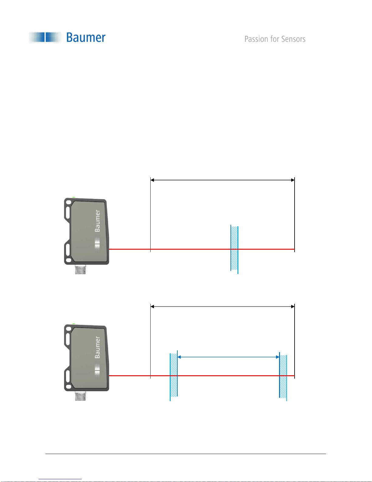
The output level can be inverted with active high or active low here. The inversion applies equally to the
yellow LED on the sensor.
4.6.6 HYSTERESIS
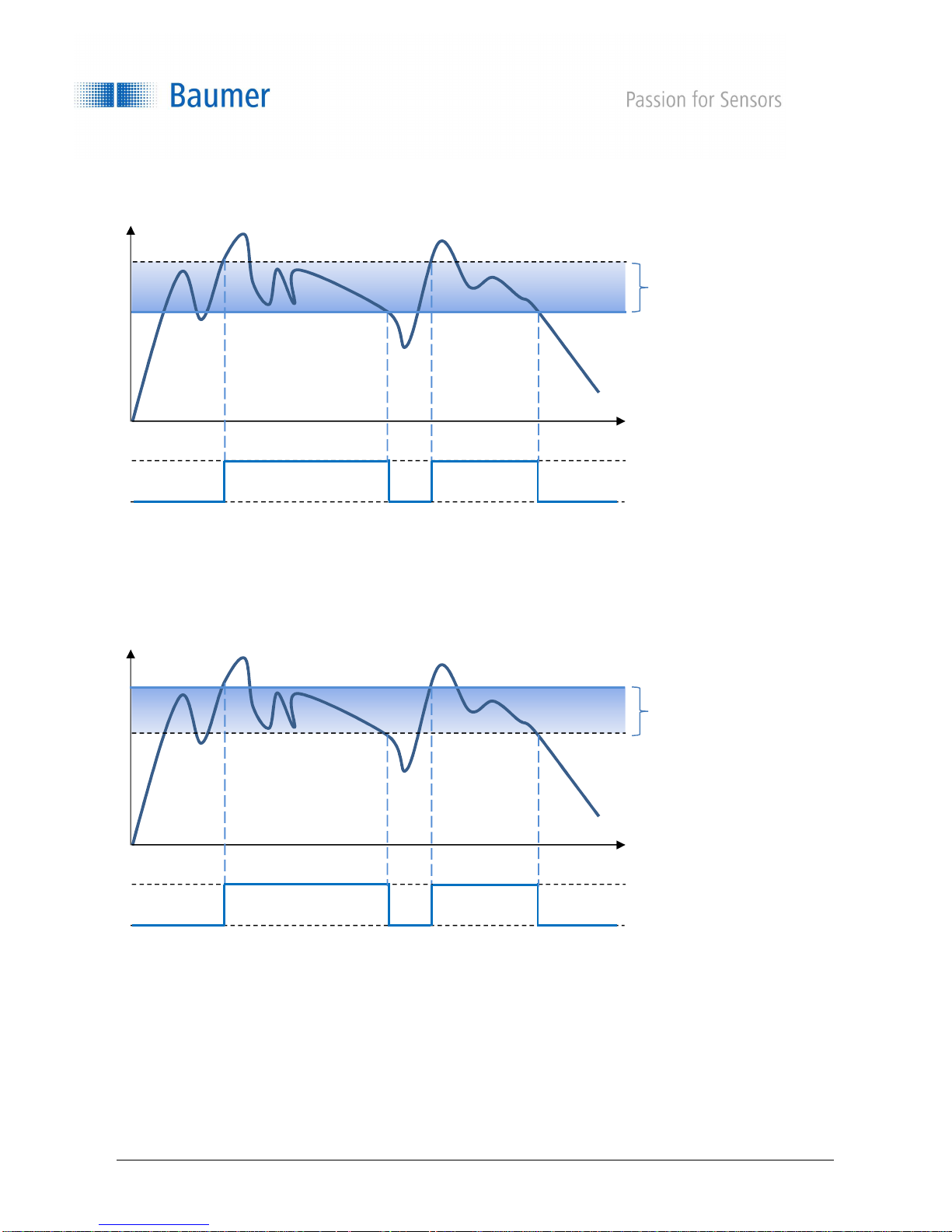
The hysteresis is the difference between the switching point and the reset point, and is specified as a value in
mm. Without hysteresis, objects in the border area of the switching point could lead to the switching output
switching on and off continuously, or to bouncing. For reasons of reliability, the use of hysteresis is
recommended (at least as great as the resolution of the sensor).
With THRESHOLD, a positive value (+) means away from the sensor, with WINDOW towards the outside. A
negative value (-) means closer to the sensor (THRESHOLD), or inside (WINDOW).
HYSTERESIS (+)
with THRESHOLD
HYSTERESIS (+)
with WINDOW
WINDOW P1
Measuring range Mr
THRESHOLD
HYSTERESIS +
Measuring range Mr
WINDOW P2
WINDOW
en_BA_OM70_point_line.docx 29/64 Baumer Electric AG
6/6/2018 8:28 AM/tof V2.0 ANW_81250853 Frauenfeld, Switzerland
HYSTERESIS +
HYSTERESIS +
Page 30
Behavior of the switching output for THRESHOLD
Active low
Active low
Example: HYSTERESIS positive
Measuring
value
Level
Example: Hysteresis negative
Measuring
value
Level
THRESHOLD
THRESHOLD
Hysteresis
High
Low
Hysteresis
High
Low
LEVEL
LEVEL
en_BA_OM70_point_line.docx 30/64 Baumer Electric AG
6/6/2018 8:28 AM/tof V2.0 ANW_81250853 Frauenfeld, Switzerland
Page 31
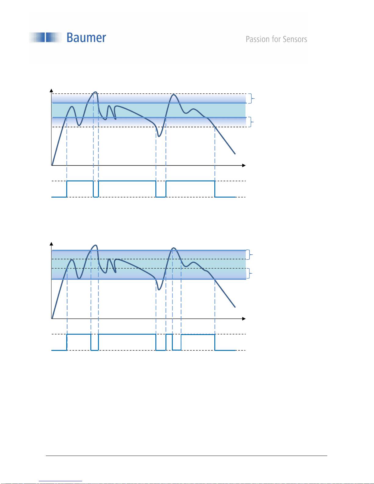
Behavior of the switching output for WINDOW
Active high
Active high
Example: HYSTERESIS positive
Measuring
value
WINDOW
Level
Example: Hysteresis negative
Measuring
value
WINDOW
Level
WINDOW P2
WINDOW P1
WINDOW P2
WINDOW P1
Hysteresis
Hysteresis
High
Low
Hysteresis
Hysteresis
High
Low
LEVEL
LEVEL
en_BA_OM70_point_line.docx 31/64 Baumer Electric AG
6/6/2018 8:28 AM/tof V2.0 ANW_81250853 Frauenfeld, Switzerland
Page 32
Sync
-
In Level
Measurement
4.7 SYSTEM
4.7.1 TRIGGER MODE
In Continuous mode, the sensor measures permanently as long as the Sync line is set to Low. As soon as
the Sync line is set to High, the sensor goes into hold mode shows no new measured values (the last
measured value is frozen), the laser is disabled.
In Single shot mode the sensor measures exactly once on the trailing edge of the Sync signal and outputs
the value. In single-shot measurements, the preset filters (see chapter PRECISION) have no effect.
Properties
• The previous measurement cycle is always completed first, even if Sync-In is on high
• While Hold is high, all outputs are frozen at their last state
• During the waiting time (Hold) the power of the laser beam is reduced (Laser off)
• Sync-In must remain on low for at least 5 µs in order for the sensor to begin measuring again
Sync-In low 0…2.5 V Run
Sync-In high 8 V…UB (operating voltage) Hold
NOTE
As soon as the Sync-In is set to high (Hold), all output functions are frozen at their
last state until the next measurement, and the laser is switched off.
en_BA_OM70_point_line.docx 32/64 Baumer Electric AG
6/6/2018 8:28 AM/tof V2.0 ANW_81250853 Frauenfeld, Switzerland
Page 33

4.7.2 RS485 BAUD
The baud rate is the number of symbols transmitted per second. The baud rate of data transmission must be
identical on the transmit and receive sides.
The sensor can be operated at the following baud rates:
• 38400
• 57600
• 115200
• 230400
• 460800
• 921600
• 1500000
4.7.3 RS485 ADDR
Every sensor has its own RS485 address, allowing the selected sensor to be addressed directly. This address
is preset to 001 and can be changed in 3 digits. Sensors must not have the same address in the same
network, to prevent the occurrence of bus conflicts. No more than 32 sensors may be connected to one bus.
4.7.4 SENSOR INFO
The sensor type and serial number are displayed here to enable clear identification of the sensor.
• SENSOR TYPE
• SERIAL NUMBER
4.7.5 LANGUAGE
Language selection:
• English
• Deutsch
• Italiano
• Français
en_BA_OM70_point_line.docx 33/64 Baumer Electric AG
6/6/2018 8:28 AM/tof V2.0 ANW_81250853 Frauenfeld, Switzerland
Page 34
4.7.6 RESET (factory settings)
This resets all settings in sensor parameters to the factory settings.
PRECISION = Very high
SCALE OUT = Max. values
ANALOG OUT = Current
CALIBRATION CURVE = Positive sensitivity
DIGITAL OUT = THRESHOLD (set to the center of the measuring range)
WINDOW P1 = Start of measuring range Sdc +10 mm
WINDOW P2 = End of measuring range Sde -10 mm
LEVEL = Active High
HYSTERESIS = % Mr
TRIGGER MODE = continuous
RS485 lock = 1 (activated)
RS485 BAUD = 57600
RS485 ADR = 1
ANALOG OUT = Current
NOTE
With "Reset", the current configuration in the sensor is overwritten and the stored
configurations are also deleted from the memory. The unit is reset to the factory
settings.
en_BA_OM70_point_line.docx 34/64 Baumer Electric AG
6/6/2018 8:28 AM/tof V2.0 ANW_81250853 Frauenfeld, Switzerland
Page 35

4.8 SETTING
The settings entered in the sensor can be applied, stored or displayed here.
4.8.1 APPLY
The settings saved under SAVE can be activated here.
• Setting 1
• Setting 2
• Setting 3
4.8.2 SAVE
The settings entered in the sensor can be stored here.
Three storage spaces are available.
• Setting 1
• Setting 2
• Setting 3
4.8.3 SHOW
SHOW
Displays the setting values.
SHOW Active
Displays the active settings.
SHOW settings 1-3
Displays the settings stored in storage spaces 1-3
The values are displayed successively; it is possible to jump to the next value using the DOWN key.
PRECISION
DIST NEAR
DIST FAR
ANALOG OUT
CHARACTER.
DIGITAL OUT
THRESHOLD
WINDOW P1
WINDOW P2
LEVEL
HYSTERESIS
TRIGGER MODE
en_BA_OM70_point_line.docx 35/64 Baumer Electric AG
6/6/2018 8:28 AM/tof V2.0 ANW_81250853 Frauenfeld, Switzerland
Page 36

4.9 Configuration using the RS-485 interface
The precision (resolution, repeat accuracy and linearity) of the output values is higher through RS-485 than
through the analog output. The use of this interface is recommended for high-precision applications. No more
than 32 sensors may be connected to one bus during operation with RS-485.
When the RS-485 interface is activated, the analog output, digital output and alarm output are deactivated or
switched as if there were no object within the measuring range. Then the sensor can only be configured
through RS-485; the display is locked for operation.
If required, the digital outputs as well as the display control can be reactivated using the relevant RS-485
commands.
See separate RS-485 manual for further information.
en_BA_OM70_point_line.docx 36/64 Baumer Electric AG
6/6/2018 8:28 AM/tof V2.0 ANW_81250853 Frauenfeld, Switzerland
Page 37
5 Operation
Response time
Measuring
5.1 Measuring frequency, measuring repeat time and response time
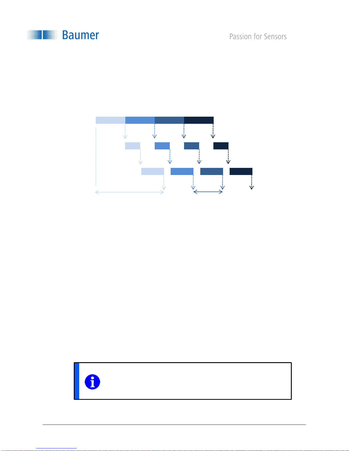
A complete measuring cycle consists of exposure, calculation and measuring value display. In order to
increase the measuring speed, process steps are executed simultaneously.
Exposure
Calculation
Measuring value display
repeat time
5.1.1 Measuring frequency and measuring repeat time
The time between two exposure times is referred to as measuring repeat time. This time can be converted into
a frequency (Hz), which indicates how many measured values can be issued by the sensor in one second.
[] =
5.1.2 Automatic exposure control
The color and surface of the object have an influence on the amount of reflected light. A longer exposure time
is required for dark objects than for light objects. The sensor automatically controls the exposure time on the
basis of the amount of light reflected by the object. This slows down the measuring frequency and the
response time. In this case, the degree of slowdown is dependent on the laser class of the sensor.
1
[]
5.2 Alarm output
The alarm signal is output as a push-pull signal (active high) when the object is outside the measuring range
or the signal quality is insufficient for evaluation. If the signal quality is insufficient, the analog and switching
outputs for 75 measuring cycles are kept at the last valid value. After this time has elapsed, the analog and
switching outputs are set as if an object were at the start of the measuring range.
NOTE
As soon as the alarm output is active, the analog and switching outputs for 75
measuring cycles are kept at the last valid value.
en_BA_OM70_point_line.docx 37/64 Baumer Electric AG
6/6/2018 8:28 AM/tof V2.0 ANW_81250853 Frauenfeld, Switzerland
Page 38
Laser
Receiver
Real distance
Measured distance
Deviation
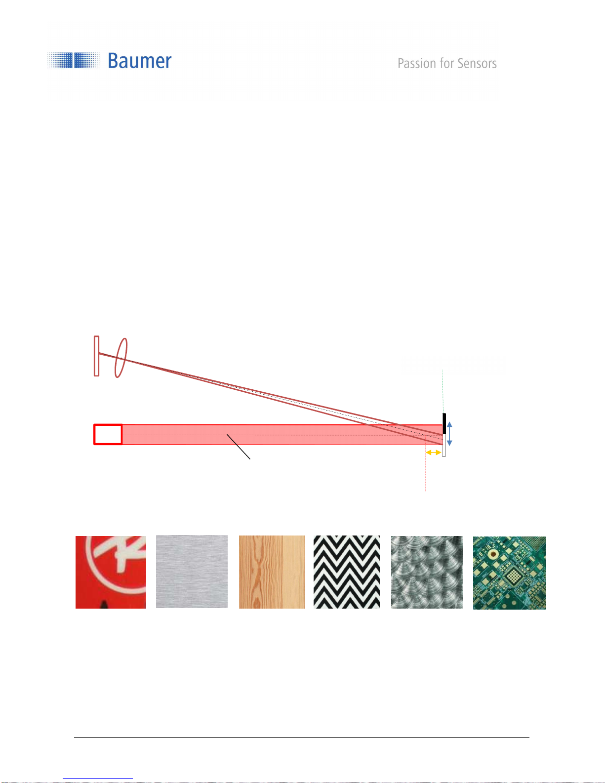
Inhomogeneous
Laser spot
5.3 Influence of ambient light
Ambient light from lamps, the sun, etc. in the view field of the sensor can lead to malfunctions or a reduction of
accuracy and should be avoided as much as possible.
5.4 Focus distance and optimal measuring distance
The size of the light spot can have a large influence on the measurement accuracy. The measured value will
not always be stable when the surface moves sideways, especially with surfaces that are inhomogeneous in
color or structure. The reason for this is the so-called color edge effect. Differences in the reflectivity or gloss
of the surface lead to a shift in the measured light distribution and thus to a distorted measured value.
5.4.1 Inhomogeneous surfaces and colored edge effect
The colour edge effect occurs with inhomogeneous surfaces. The measured value is distorted by the
light/dark surface and changes when the inhomogeneous object is moved across the laser beam.
Color edge effect:
Examples for inhomogeneous objects:
object
en_BA_OM70_point_line.docx 38/64 Baumer Electric AG
6/6/2018 8:28 AM/tof V2.0 ANW_81250853 Frauenfeld, Switzerland
Page 39
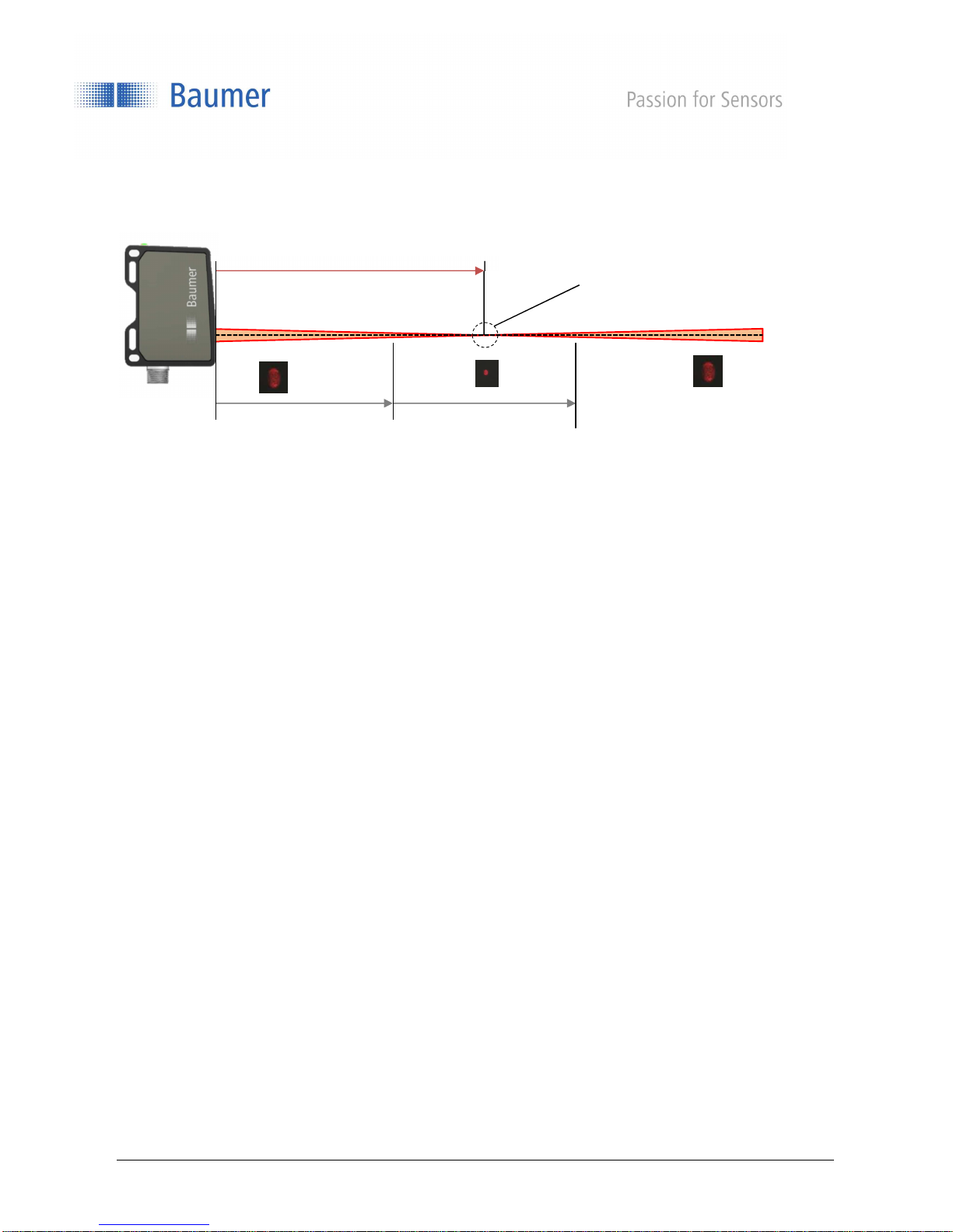
5.4.2 Influence of the light spot size
Focal distance
Focus point
Smallest light spot
Optimal measuring distance
(Small light spot)
The size of the light spot has a great influence on the colour edge effect. This influence can be greatly
minimized by a small light spot and thus the accuracy of the measured value can be improved.
Sdo
The focus distance determines the smallest light spot diameter, around this focus point lies the optimal
measuring distance Sdo, in which the light spot is very small.
Summarized:
• To measure inhomogeneous surfaces robustly and accurately, it is recommended to measure as
close as possible to the sensor and as close as possible to the focus point
• If the entire measuring range is to be used, it is recommended to use the sensor type with the focus
point as far away from the sensor as possible
en_BA_OM70_point_line.docx 39/64 Baumer Electric AG
6/6/2018 8:28 AM/tof V2.0 ANW_81250853 Frauenfeld, Switzerland
Page 40

5.5 Error correction and tips
Error Error correction
No function • Check connection. Power supply 15…28 VDC on pin 2 (+Vs,
brown) and pin 7 (GND, blue)
Green LED flashes • Short circuit on switching outputs. Check connection.
Red LED lights up • Object outside measuring field (near, far or to the side)
• Amplitude of the received signal is insufficient (e.g. in case of
soiling)
Touch panel cannot be operated • Touch panel locked. Re-enable panel for operation by sliding a
finger over the 4 keys from left to right.
• RS-485 controls the sensor--> operation via the touch panel not
possible at the same time
• RS-485 locks the touch keys--> the touch panel was locked via
RS-485 and can only be re-enabled with a command via RS-485
Touch panel does not react • Clean panel. The panel is dirty or wet, which makes it harder to
press the keys
Sensor does not provide the
expected measuring results
Unreliable measuring value:
The measuring value jumps
back and forth
Transmitting laser light is dim Sync-In input is on High--> set to Low
• The object is not in the measuring range
• Bright object, avoid direct reflexes from the transmitter to the
receiver
• The object is not in the measuring range
• Avoid bright object
• Avoid very dark object
• Too much ambient light
en_BA_OM70_point_line.docx 40/64 Baumer Electric AG
6/6/2018 8:28 AM/tof V2.0 ANW_81250853 Frauenfeld, Switzerland
Page 41

6 Safety instructions and maintenance
6.1 General safety instructions
Intended use
This product is a precision device and is used for object detection and the preparation and/or provision of
measuring values as electrical quantities for a subsequent system. Unless this product is specially labeled, it
must not be used for operation in potentially explosive environments.
Commissioning
Installation, mounting and adjustment of this product may be performed only by a qualified person.
Installation
For mounting, use only the mechanical mountings and mechanical mounting accessories intended for this
product. Unused outputs must not be wired. In cable versions with unused cores, these cores must be
insulated. Always comply with admissible cable bending radii. Prior to electrical connection of the product, the
system must be disconnected from the power supply. In areas where shielded cables are mandatory, they
must be used as protection against electromagnetic disturbances. If the customer makes plug connections to
shielded cables, an EMC version of the connectors should be used, and the shield must be connected to the
connector housing across a large area.
Caution
Deviation from the procedures and settings specified here can lead to hazardous radiation effects.
en_BA_OM70_point_line.docx 41/64 Baumer Electric AG
6/6/2018 8:28 AM/tof V2.0 ANW_81250853 Frauenfeld, Switzerland
Page 42
6.2 Sensor inscriptions
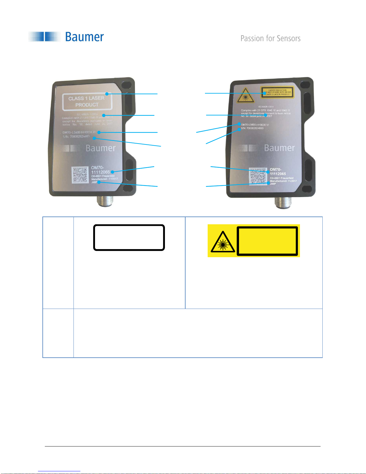
Information and
warning plate
FDA certification plate
Article name
Serial number
Material number
Production code
Class 1: No risk for eyes
CLASS 1 LASER
PRODUCT
Class 1 lasers are safe under reasonably
foreseeable operational conditions of
normal use, including direct long-term
viewing of the beam, even when exposure
occurs using a magnifying optic.
Information and warning plate
Accidental short-term exposure (up to 0.25 s) does
not damage the eye, because the corneal reflex can
automatically protect the eye sufficiently from longer
radiation. Class 2 lasers may be used without any
further protection if intentional staring into the beam
is not required for the application.
Class 2: Do not stare into the beam
LASER RADI ATION
DO NOT S TARE IN TO BEAM
W avelength: 640...670nm
IEC 60825-1, Ed. 3, 2014
CLASS 2 LASER PRODUCT
Complies with 21 CFR 1040.10 and 1040.11
FDA
plate
except for deviations pursuant to laser
notice No. 50, dated June 24, 2007
IEC 60825-1/2014
certification
en_BA_OM70_point_line.docx 42/64 Baumer Electric AG
6/6/2018 8:28 AM/tof V2.0 ANW_81250853 Frauenfeld, Switzerland
Page 43
6.3 Front optic
In the event of a broken front optic, defective display, or loose or exposed laser lens, the sensor must be
disconnected from the power supply immediately. It must not be put into operation again. Non-compliance
with these safety instructions may lead to the release of hazardous laser beams.
ATTENTION!
The use of a sensor with a broken front optic or loose or exposed lens can
lead to hazardous laser radiation.
6.4 Cleaning the sensors
The laser distance sensors do not require any maintenance, except that the front window must be kept clean.
Dust and fingerprints can impair sensor function. It is normally sufficient to wipe the windows with a dry, clean
(!), soft lens cleaning cloth. Alcohol or soapy water can be used in case of severe soiling.
The display and the keys must be kept free from dirt and moisture. Water and dirt on the keys can impair their
function.
6.5 Disposal
This sensor contains electronic components. Dispose of parts according to country-specific provisions.
en_BA_OM70_point_line.docx 43/64 Baumer Electric AG
6/6/2018 8:28 AM/tof V2.0 ANW_81250853 Frauenfeld, Switzerland
Page 44

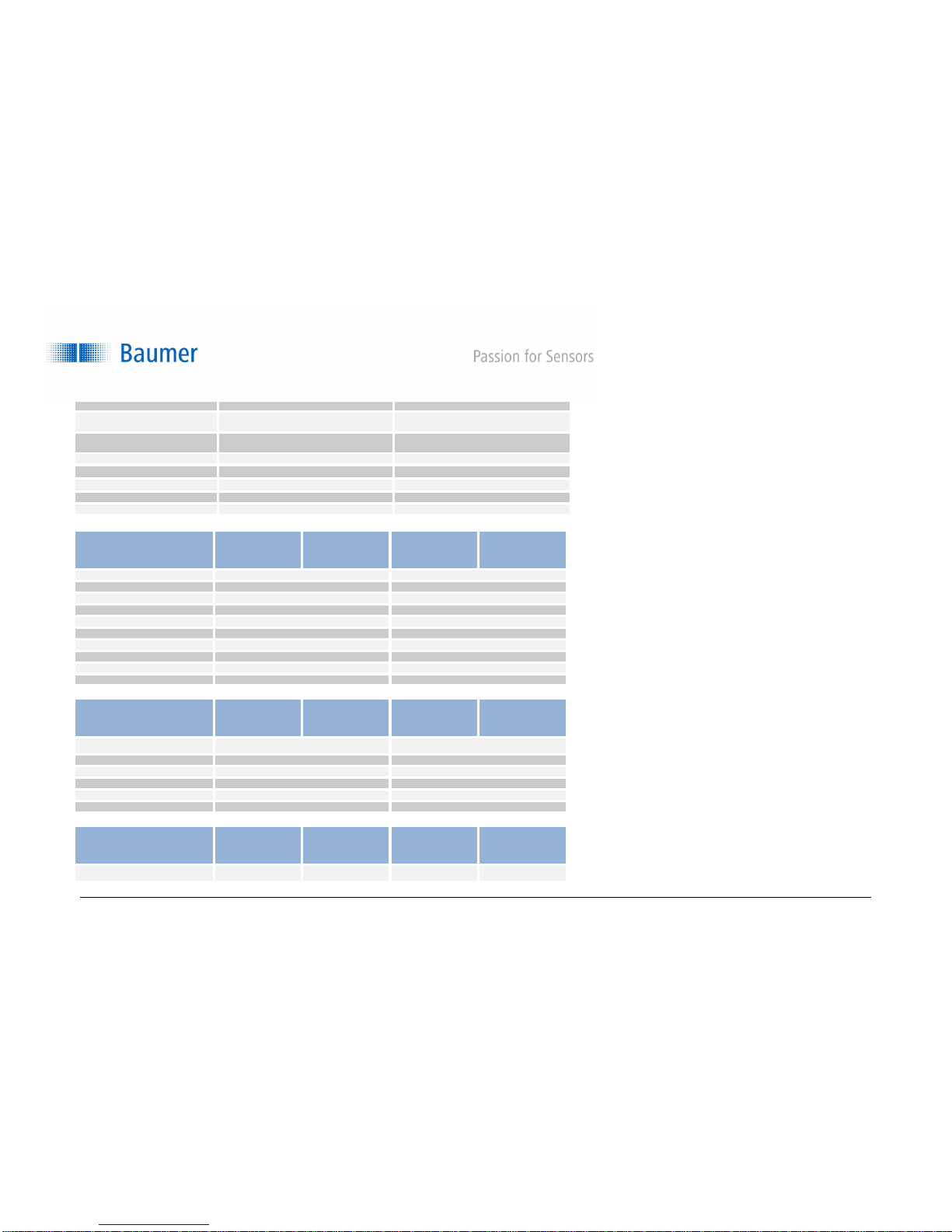
7 Sensor data sheet
7.1 Measuring range types 30…70 mm
General data
11200060
Laser class 1
Laser point
Focal dist. 48 mm
11200056
Laser class 1
Laser line
Focal dist. 48 mm
11195785
Laser class 1
Laser point
Focal dist. 65 mm
11112017
Laser class 1
Laser line
Focal dist. 65 mm
Beam shape Laser point Laser line Laser point Laser line
Laser class 1 1
Function Distance Distance
Measuring range (distance) 30…70 mm 30…70 mm
Start of
measuring range Sdc
30 mm 30 mm
End of measuring range Sde
70 mm 70 mm
Blind region 0…30 mm 0…30 mm
Measuring range Mr 40 mm 40 mm
Sweet spot 48 mm 65 mm
Focal range 40…55 mm 55…70 mm
Measuring frequency
2500 Hz
1
2
2500 Hz
1
2
Response time
- Single shot
- Continuous
0.8 ms12
1.2 ms12
0.8 ms12
1.2 ms12
Resolution
Without filter
Precision high
Precision very high
Precision highest
2.6…4 µm12
1.3…2 µm
123
0.9…1.4 µm
123
0.7…1 µm
123
2.6…4 µm12
1.3…2 µm
123
0.9…1.4 µm
123
0.7…1 µm
123
Spatial repeatability 14 µm 14 µm
Repeat accuracy in time
Without filter
Precision high
Precision very high
Precision highest
0.4…1.2 µm12
0.2…0.6 µm
123
0.2…0.4 µm
123
0.1…0.3 µm
123
0.4…1.2 µm12
0.2…0.6 µm
123
0.2…0.4 µm
123
0.1…0.3 µm
123
Linearity error
± 22 µm
1
2
± 22 µm
1
2
Linearity deviation in % of Mr
± 0.06%
1
2
± 0.06%
1
2
Temperature drift
± 0.01% Sde/K
1
2
± 0.01% Sde/K
1
2
PRECISION filter values:
Standard
High
Very high
Highest
Median Average
Off Off
9 Off
9 16
9 128
Median Average
Off Off
9 Off
9 16
9 128
1
Measurements with standard Baumer measuring equipment and objects dependent on measuring range Sd
2
Measurement on 90% reflectivity (white)
3
Measurement with filtering
Page 45
en_BA_OM70_point_line.docx 45/64 Baumer Electric AG
6/6/2018 8:28 AM/tof V2.0 ANW_81250853 Frauenfeld, Switzerland
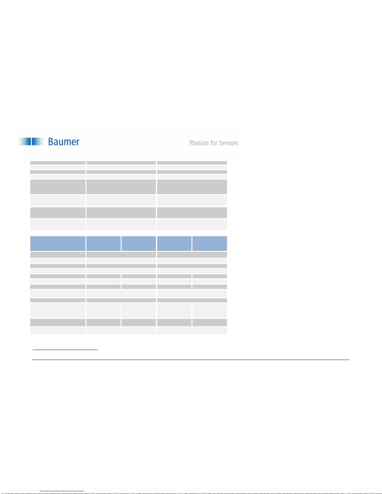
Hysteresis digital output Adjustable in mm Adjustable in mm
Minimum window size for digital
output
0.07 mm 0.07 mm
Minimum window size
for analog
output
1 mm 1 mm
Power on indication Green LED Green LED
Output indicator Yellow LED / red LED Yellow LED / red LED
Switch-on delay <1200 ms <1200 ms
Light source Red laser diode, pulsed Red laser diode, pulsed
Setting Touch display, RS-485 Touch display, RS-485
Electrical data
11200060
Laser class 1
Laser point
Focal dist. 48 mm
11200056
Laser class 1
Laser line
Focal dist. 48 mm
11195785
Laser class 1
Laser point
Focal dist. 65 mm
11112017
Laser class 1
Laser line
Focal dist. 65 mm
Voltage supply range +Vs
15 ... 28 VDC
15 ... 28 VDC
Max. supply current (without load) 120 mA 120 mA
Output circuit
Analog and RS
-
485 Analog and RS
-
485
Output signal
4 ... 20 mA / 0 ... 10 VDC (adjustable)
4 ... 20 mA / 0 ... 10 VDC (adjustable)
Switching output Push-pull Push-pull
Output function Out 1 / alarm Out 1 / alarm
Output current < 100 mA < 100 mA
Baud rate Adjustable Adjustable
Reverse polarity protection Yes, Vs to GND Yes, Vs to GND
Short circuit protection
Yes Yes
Mechanical data
11200060
Laser class 1
Laser point
Focal dist. 48 mm
11200056
Laser class 1
Laser line
Focal dist. 48 mm
11195785
Laser class 1
Laser point
Focal dist. 65 mm
11112017
Laser class 1
Laser line
Focal dist. 65 mm
Width / Height / Length
26 / 74 / 55 mm 26 / 74 / 55 mm
Design Rectangular, front view Rectangular, front view
Housing material Aluminum Aluminum
Front optic
Glass Glass
Connection method Plug M12 8-pole Plug M12 8-pole
Weight 130 g 130 g
Ambient conditions
11200060
Laser class 1
Laser point
Focal dist. 48 mm
11200056
Laser class 1
Laser line
Focal dist. 48 mm
11195785
Laser class 1
Laser point
Focal dist. 65 mm
11112017
Laser class 1
Laser line
Focal dist. 65 mm
Ambient light immunity
< 28 kLux < 28 kLux < 28 kLux < 28 kLux
Page 46
en_BA_OM70_point_line.docx 46/64 Baumer Electric AG
6/6/2018 8:28 AM/tof V2.0 ANW_81250853 Frauenfeld, Switzerland
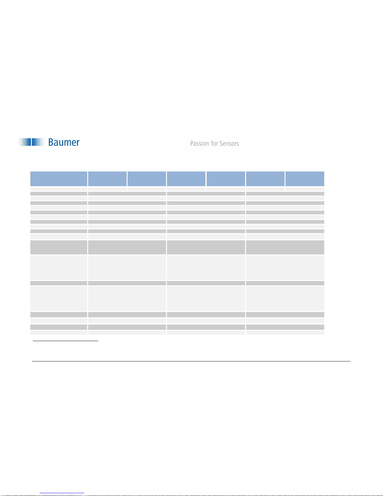
Operating temperature -10 … +50 °C -10 … +50 °C
Storage temperature -20 … +60 °C -20 … +60 °C
Heating period
20 min. 20 min.
protection class IP 67 IP 67
Vibration resistance (sinusoidal)
IEC 60068
-2-
6:2008
± 0.75mm p-p for f = 10 - 58Hz , 10 cycles for
each axis 10g for f = 58 -2,000Hz, 10 cycles
for each axis
IEC 60068
-2-
6:2008
± 0.75mm p-p for f = 10 - 58Hz , 10 cycles for
each axis 10g for f = 58 -2,000Hz, 10 cycles
for each axis
Vibration resistance (random)
IEC 60068
-2-
64:2008
Spectrum: 0.1 g2/Hz for 20 – 1,000Hz, 300
minutes / axis (>10.6g RMS)
IEC 60068
-2-
64:2008
Spectrum: 0.1 g2/Hz for 20 – 1,000Hz, 300
minutes / axis (>10.6g RMS)
Shock resistance
IEC 60068
-2-
27:2009
50g / 11ms and 100g / 6ms, 10 shocks in each
axis and each direction
IEC 60068
-2-
27:2009
50g / 11ms and 100g / 6ms, 10 shocks in each
axis and each direction
Impact resistance
IEC 60068
-2-27
100g / 2ms, 5,000 shocks in each axis and
each direction
IEC 60068
-2-27
100g / 2ms, 5,000 shocks in each axis and
each direction
Optical properties
11200060
Laser class 1
Laser point
Focal dist. 48 mm
11200056
Laser class 1
Laser line
Focal dist. 48 mm
11195785
Laser class 1
Laser point
Focal dist. 65 mm
11112017
Laser class 1
Laser line
Focal dist. 65 mm
Light
source
AlGaInP laser diode AlGaInP laser diode
Wave length 660 nm 660 nm
Operating mode pulsed pulsed
Pulse duration 4 µs…2.5 ms 4 µs…2.5 ms 4 µs…2.5 ms 4 µs…2.5 ms
Pulse period
0.4…5 ms
0.4…5 ms
0.4…5 ms
0.4…5 ms
Total emitted pulse power 0.24mW 0.29mW 0.24mW 0.24mW
Beam shape Point laser Short line Point laser Short line
Receiver position
L1
L2
34 mm
50 mm
34 mm
50 mm
Focal distance df 48 mm 65 mm
Laser point size
@Start of measuring range
@Center of measuring range
@End of measuring range
tbd
tbd
tbd
tbd
tbd
tbd
tbd
tbd
tbd
tbd
tbd
tbd
Nominal ocular hazard distance
(NOHD)1
N/A N/A N/A N/A
Laser classification (as per IEC
60825-1/2014)
Laser class 1 Laser class 1
1
Outside the "Nominal ocular hazard distance", the radiation exposure is below the limit value of laser class 1
Page 47
en_BA_OM70_point_line.docx 47/64 Baumer Electric AG
6/6/2018 8:28 AM/tof V2.0 ANW_81250853 Frauenfeld, Switzerland
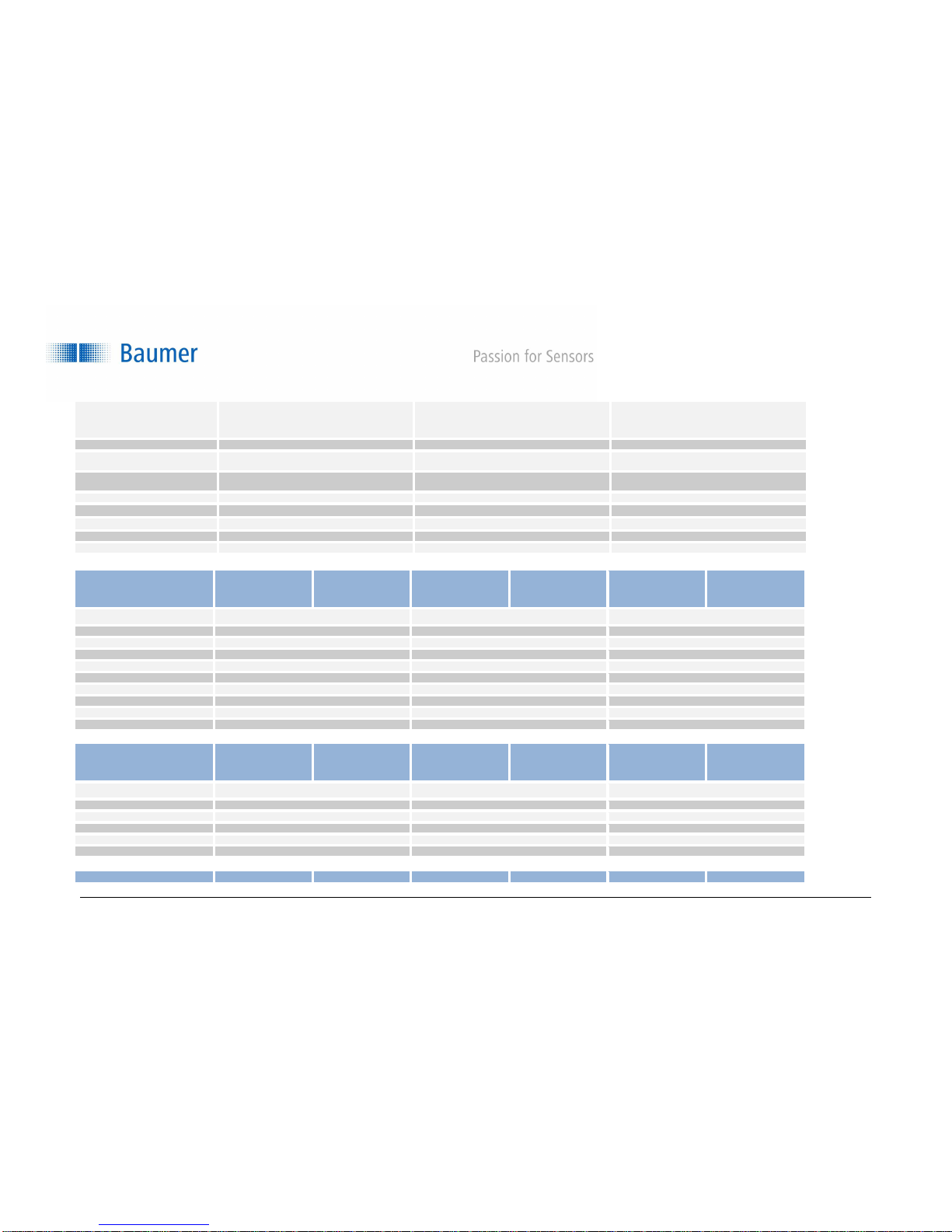
7.1 Measuring range types 40…140 mm
General data
11200061
Laser class 1
Laser point
Focal dist. 70 mm
11200062
Laser class 1
Laser line
Focal dist. 70 mm
11200063
Laser class 1
Laser point
Focal dist. 100 mm
11200064
Laser class 1
Laser line
Focal dist. 100 mm
11112018
Laser class 1
Laser point
Focal dist. 130 mm
11112019
Laser class 1
Laser line
Focal dist. 130 mm
Beam shape
Laser point
Laser line
Laser point
Laser line
Laser point
Laser line
Laser class 1 1 1
Function Distance Distance Distance
Measuring range (distance) 40…140 mm 40…140 mm 40…140 mm
Start of measuring range Sdc 40 mm 40 mm 40 mm
End of measuring range Sde 140 mm 140 mm 140 mm
Blind region 0…40 mm 0…40 mm 0…40 mm
Measuring range Mr
100 mm 100 mm 100 mm
Sweet spot 70 mm 100 mm 130 mm
Focal range 50…90 mm 80…120 mm 110…140 mm
Measuring frequency
2500 Hz
1
2
2500 Hz
1
2
2500 Hz
1
2
Response time
- Single shot
- Continuous
0.8 ms12
1.2 ms12
0.8 ms12
1.2 ms12
0.8 ms12
1.2 ms12
Resolution
Without filter
Precision high
Precision very high
Precision highest
4.8…10 µm12
2.4…5 µm
123
1.6…3.4 µm
123
1.2…2.5 µm
123
4.8…10 µm12
2.4…5 µm
123
1.6…3.4 µm
123
1.2…2.5 µm
123
4.8…10 µm12
2.4…5 µm
123
1.6…3.4 µm
123
1.2…2.5 µm
123
Spatial repeatability 22 µm
22 µm
22 µm
Repeat accuracy in time
Without filter
Precision high
Precision very high
Precision highest
1…2.5 µm12
0.5…1.3 µm
123
0.4…0.9 µm
123
0.3…0.7 µm
123
1…2.5 µm12
0.5…1.3 µm
123
0.4…0.9 µm
123
0.3…0.7 µm
123
1…2.5 µm12
0.5…1.3 µm
123
0.4…0.9 µm
123
0.3…0.7 µm
123
Linearity error
± 65 µm
1
2
± 65 µm
1
2
± 65 µm
1
2
Linearity deviation in % of Mr
± 0.07%
1
2
± 0.07%
1
2
± 0.07%
1
2
Temperature drift
± 0.015% Sde/K
1
2
± 0.015% Sde/K
1
2
± 0.015% Sde/K
1
2
PRECISION filter values: Median Average Median Average Median Average
1
Measurements with standard Baumer measuring equipment and objects dependent on measuring range Sd
2
Measurement on 90% reflectivity (white)
3
Measurement with filtering
Page 48
en_BA_OM70_point_line.docx 48/64 Baumer Electric AG
6/6/2018 8:28 AM/tof V2.0 ANW_81250853 Frauenfeld, Switzerland
Standard
High
Very high
Highest
Off Off
9 Off
9 16
9 128
Off Off
9 Off
9 16
9 128
Off Off
9 Off
9 16
9 128
Hysteresis digital output
Adjustable in mm
Adjustable in mm
Adjustable in mm
Minimum window size for digital
output
0.14 mm 0.14 mm 0.14 mm
Minimum window size for analog
output
1 mm 1 mm 1 mm
Power on indication Green LED Green LED Green LED
Output indicator Yellow LED / red LED Yellow LED / red LED Yellow LED / red LED
Switch-on delay <1200 ms <1200 ms <1200 ms
Light source Red laser diode, pulsed Red laser diode, pulsed Red laser diode, pulsed
Setting Touch display, RS-485 Touch display, RS-485 Touch display, RS-485
Electrical data
11200061
Laser class 1
Laser point
Focal dist. 70 mm
11200062
Laser class 1
Laser line
Focal dist. 70 mm
11200063
Laser class 1
Laser point
Focal dist. 100 mm
11200064
Laser class 1
Laser line
Focal dist. 100 mm
11112018
Laser class 1
Laser point
Focal dist. 130 mm
11112019
Laser class 1
Laser line
Focal dist. 130 mm
Voltage supply range +Vs
15 ... 28 VDC 15 ... 28 VDC 15 ... 28 VDC
Max. supply current (without load) 120 mA 120 mA 120 mA
Output circuit Analog and RS-485 Analog and RS-485 Analog and RS-485
Output signal 4 ... 20 mA / 0 ... 10 VDC (adjustable) 4 ... 20 mA / 0 ... 10 VDC (adjustable) 4 ... 20 mA / 0 ... 10 VDC (adjustable)
Switching output
Push-pull Push-pull Push-pull
Output function
Out 1 / alarm
Out 1 / alarm
Out 1 / alarm
Output current < 100 mA < 100 mA < 100 mA
Baud rate Adjustable Adjustable Adjustable
Reverse polarity protection Yes, Vs to GND Yes, Vs to GND Yes, Vs to GND
Short circuit protection Yes Yes Yes
Mechanical data
11200061
Laser class 1
Laser point
Focal dist. 70 mm
11200062
Laser class 1
Laser line
Focal dist. 70 mm
11200063
Laser class 1
Laser point
Focal dist. 100 mm
11200064
Laser class 1
Laser line
Focal dist. 100 mm
11112018
Laser class 1
Laser point
Focal dist. 130 mm
11112019
Laser class 1
Laser line
Focal dist. 130 mm
Width / Height / Length
26 / 74 / 55 mm 26 / 74 / 55 mm 26 / 74 / 55 mm
Design Rectangular, front view Rectangular, front view Rectangular, front view
Housing material Aluminum Aluminum Aluminum
Front optic Glass Glass Glass
Connection method Plug M12 8-pole Plug M12 8-pole Plug M12 8-pole
Weight 130 g 130 g 130 g
Ambient conditions
11200061
11200062
11200063
11200064
11112018
11112019
Page 49
en_BA_OM70_point_line.docx 49/64 Baumer Electric AG
6/6/2018 8:28 AM/tof V2.0 ANW_81250853 Frauenfeld, Switzerland
Laser class 1
Laser point
Focal dist. 70 mm
Laser class 1
Laser line
Focal dist. 70 mm
Laser class 1
Laser point
Focal dist. 100 mm
Laser class 1
Laser line
Focal dist. 100 mm
Laser class 1
Laser point
Focal dist. 130 mm
Laser class 1
Laser line
Focal dist. 130 mm
Ambient
light immunity
< 35 kLux < 35 kLux < 35 kLux
Operating temperature -10 … +50 °C -10 … +50 °C -10 … +50 °C
Storage temperature -20 … +60 °C -20 … +60 °C -20 … +60 °C
Heating period
20 min. 20 min. 20 min.
protection class IP 67 IP 67 IP 67
Vibration resistance (sinusoidal)
IEC 60068
-2-
6:2008
± 0.75mm p-p for f = 10 - 58Hz , 10 cycles for each
axis 10g for f = 58 -2,000Hz, 10 cycles for each axis
IEC 60068
-2-
6:2008
± 0.75mm p-p for f = 10 - 58Hz , 10 cycles for each
axis 10g for f = 58 -2,000Hz, 10 cycles for each axis
IEC 60068
-2-
6:2008
± 0.75mm p-p for f = 10 - 58Hz , 10 cycles for each
axis 10g for f = 58 -2,000Hz, 10 cycles for each axis
Vibration resistance (random)
IEC 60068
-2-
64:2008
Spectrum: 0.1 g2/Hz for 20 – 1,000Hz, 300 minutes /
axis (>10.6g RMS)
IEC 60068
-2-
64:2008
Spectrum: 0.1 g2/Hz for 20 – 1,000Hz, 300 minutes /
axis (>10.6g RMS)
IEC 60068
-2-
64:2008
Spectrum: 0.1 g2/Hz for 20 – 1,000Hz, 300 minutes /
axis (>10.6g RMS)
Shock resistance
IEC 60068
-2-
27:2009
50g / 11ms and 100g / 6ms, 10 shocks in each axis
and each direction
IEC 60068
-2-
27:2009
50g / 11ms and 100g / 6ms, 10 shocks in each axis
and each direction
IEC 60068
-2-
27:2009
50g / 11ms and 100g / 6ms, 10 shocks in each axis
and each direction
Impact resistance
IEC 60068
-2-27
100g / 2ms, 5,000 shocks in each axis and each
direction
IEC 60068
-2-27
100g / 2ms, 5,000 shocks in each axis and each
direction
IEC 60068
-2-27
100g / 2ms, 5,000 shocks in each axis and each
direction
Optical properties
11200061
Laser class 1
Laser point
Focal dist. 70 mm
11200062
Laser class 1
Laser line
Focal dist. 70 mm
11200063
Laser class 1
Laser point
Focal dist. 100 mm
11200064
Laser class 1
Laser line
Focal dist. 100 mm
11112018
Laser class 1
Laser point
Focal dist. 130 mm
11112019
Laser class 1
Laser line
Focal dist. 130 mm
Light source
AlGaInP laser diode AlGaInP laser diode AlGaInP laser diode
Wave length 660 nm 660 nm 660 nm
Operating mode pulsed pulsed pulsed
Pulse duration
4 µs…2.5
ms 4 µs…2.5
ms 4 µs…2.5
ms 4 µs…2.5
ms 4 µs…2.5
ms 4
µs…2.5ms
Pulse period 0.4…5 ms 0.4…5 ms 0.4…5 ms 0.4…5 ms 0.4…5 ms 0.4…5 ms
Total emitted pulse power 0.2 mW 0.2 mW 0.2 mW 0.2 mW 0.28 mW 0.27 mW
Beam shape Point laser Short line Point laser Short line Point laser Short line
Receiver position
L1
L2
36 mm
53 mm
36 mm
53 mm
36 mm
53 mm
Focal distance df 70 mm 100 mm 130 mm
Laser point size
@Start of measuring range
@Center of measuring range
@End of measuring range
tbd
tbd
tbd
tbd
tbd
tbd
tbd
tbd
tbd
tbd
tbd
tbd
tbd
tbd
tbd
tbd
tbd
tbd
Nominal ocular hazard distance
(NOHD)1
N/A N/A N/A N/A N/A N/A
1
Outside the "Nominal ocular hazard distance", the radiation exposure is below the limit value of laser class 1
Page 50
en_BA_OM70_point_line.docx 50/64 Baumer Electric AG
6/6/2018 8:28 AM/tof V2.0 ANW_81250853 Frauenfeld, Switzerland
Laser classification (as per IEC
60825-1/2014)
Laser class 1 Laser class 1 Laser class 1
7.1 Measuring range types 50…250 mm
General data
11200065
Laser class 1
Laser point
Focal dist. 130 mm
11200066
Laser class 1
Laser line
Focal dist. 130 mm
11200067
Laser class 1
Laser point
Focal dist. 180 mm
11200068
Laser class 1
Laser line
Focal dist. 180 mm
11112060
Laser class 1
Laser point
Focal dist. 240 mm
11200061
Laser class 1
Laser line
Focal dist. 240 mm
Beam shape Laser point Laser line Laser point Laser line Laser point Laser line
Laser class 1 1 1
Function Distance Distance Distance
Measuring range (distance)
50…250 mm
50…250 mm
50…250 mm
Start of measuring range Sdc 50 mm 50 mm 50 mm
End of measuring range Sde 250 mm 250 mm 250 mm
Blind region 0…50 mm 0…50 mm 0…50 mm
Measuring range Mr 200 mm 200 mm 200 mm
Sweet spot 130 mm 180 mm 240 mm
Focal range
100…150 mm
140…210 mm
200…250 mm
Measuring frequency
2500 Hz
1
2
2500 Hz
1
2
2500 Hz
1
2
Response time
- Single shot
- Continuous
0.8 ms12
1.2 ms12
0.8 ms12
1.2 ms12
0.8 ms12
1.2 ms12
Resolution
Without filter
Precision high
Precision very high
Precision highest
5.3…25 µm12
2.7…12.5 µm
123
1.8…8.4 µm
123
1.4…6.3 µm
123
5.3…25 µm12
2.7…12.5 µm
123
1.8…8.4 µm
123
1.4…6.3 µm
123
5.3…25 µm12
2.7…12.5 µm
123
1.8…8.4 µm
123
1.4…6.3 µm
123
Spatial repeatability 60 µm
60 µm
60 µm
Repeat accuracy in time
Without filter
Precision high
Precision very high
Precision highest
1…8 µm12
0.5…4 µm
123
0.4…2.7 µm
123
0.3…2 µm
123
1…8 µm12
0.5…4 µm
123
0.4…2.7 µm
123
0.3…2 µm
123
1…8 µm12
0.5…4 µm
123
0.4…2.7 µm
123
0.3…2 µm
123
Linearity error
± 170 µm
1
2
± 170 µm
1
2
± 170 µm
1
2
Linearity deviation in % of Mr
± 0.09%
1
2
± 0.09%
1
2
± 0.09%
1
2
1
Measurements with standard Baumer measuring equipment and objects dependent on measuring range Sd
2
Measurement on 90% reflectivity (white)
3
Measurement with filtering
Page 51
en_BA_OM70_point_line.docx 51/64 Baumer Electric AG
6/6/2018 8:28 AM/tof V2.0 ANW_81250853 Frauenfeld, Switzerland
Temperature drift
± 0.024% Sde/K
1
2
± 0.024% Sde/K
1
2
± 0.024% Sde/K
1
2
PRECISION filter values:
Standard
High
Very high
Highest
Median Average
Off Off
9 Off
9 16
9 128
Median Average
Off Off
9 Off
9 16
9 128
Median Average
Off Off
9 Off
9 16
9 128
Hysteresis digital output Adjustable in mm Adjustable in mm Adjustable in mm
Minimum window size for digital
output
0.25 mm 0.25 mm 0.25 mm
Minimum window size for analog
output
1 mm 1 mm 1 mm
Power on indication Green LED Green LED Green LED
Output indicator Yellow LED / red LED Yellow LED / red LED Yellow LED / red LED
Switch-on delay <1200 ms <1200 ms <1200 ms
Light source Red laser diode, pulsed Red laser diode, pulsed Red laser diode, pulsed
Setting Touch display, RS-485 Touch display, RS-485 Touch display, RS-485
Electrical data
11200065
Laser class 1
Laser point
Focal dist. 130 mm
11200066
Laser class 1
Laser line
Focal dist. 130 mm
11200067
Laser class 1
Laser point
Focal dist. 180 mm
11200068
Laser class 1
Laser line
Focal dist. 180 mm
11112060
Laser class 1
Laser point
Focal dist. 240 mm
11200061
Laser class 1
Laser line
Focal dist. 240 mm
Voltage supply range +Vs
15 ... 28 VDC 15 ... 28 VDC 15 ... 28 VDC
Max. supply current (without load) 120 mA 120 mA 120 mA
Output circuit Analog and RS-485 Analog and RS-485 Analog and RS-485
Output signal 4 ... 20 mA / 0 ... 10 VDC (adjustable) 4 ... 20 mA / 0 ... 10 VDC (adjustable) 4 ... 20 mA / 0 ... 10 VDC (adjustable)
Switching output Push-pull Push-pull Push-pull
Output function
Out 1 / alarm
Out 1 / alarm
Out 1 / alarm
Output current < 100 mA < 100 mA < 100 mA
Baud rate Adjustable Adjustable Adjustable
Reverse polarity protection Yes, Vs to GND Yes, Vs to GND Yes, Vs to GND
Short circuit protection Yes Yes Yes
Mechanical data
11200065
Laser class 1
Laser point
Focal dist. 130 mm
11200066
Laser class 1
Laser line
Focal dist. 130 mm
11200067
Laser class 1
Laser point
Focal dist. 180 mm
11200068
Laser class 1
Laser line
Focal dist. 180 mm
11112060
Laser class 1
Laser point
Focal dist. 240 mm
11200061
Laser class 1
Laser line
Focal dist. 240 mm
Width / Height / Length
26 / 74 / 55 mm 26 / 74 / 55 mm 26 / 74 / 55 mm
Design Rectangular, front view Rectangular, front view Rectangular, front view
Housing material Aluminum Aluminum Aluminum
Front optic Glass Glass Glass
Connection method Plug M12 8-pole Plug M12 8-pole Plug M12 8-pole
Weight 130 g 130 g 130 g
Page 52
en_BA_OM70_point_line.docx 52/64 Baumer Electric AG
6/6/2018 8:28 AM/tof V2.0 ANW_81250853 Frauenfeld, Switzerland
Ambient conditions
11200065
Laser class 1
Laser point
Focal dist. 130 mm
11200066
Laser class 1
Laser line
Focal dist. 130 mm
11200067
Laser class 1
Laser point
Focal dist. 180 mm
11200068
Laser class 1
Laser line
Focal dist. 180 mm
11112060
Laser class 1
Laser point
Focal dist. 240 mm
11200061
Laser class 1
Laser line
Focal dist. 240 mm
Ambient light immunity
< 170 kLux < 170 kLux < 170 kLux
Operating temperature -10 … +50 °C -10 … +50 °C -10 … +50 °C
Storage temperature -20 … +60 °C -20 … +60 °C -20 … +60 °C
Heating period 20 min. 20 min. 20 min.
protection class IP 67 IP 67 IP 67
Vibration resistance (sinusoidal)
IEC 60068
-2-
6:2008
± 0.75mm p-p for f = 10 - 58Hz , 10 cycles for each
axis 10g for f = 58 -2,000Hz, 10 cycles for each axis
IEC 60068
-2-
6:2008
± 0.75mm p-p for f = 10 - 58Hz , 10 cycles for each
axis 10g for f = 58 -2,000Hz, 10 cycles for each axis
IEC 60068
-2-
6:2008
± 0.75mm p-p for f = 10 - 58Hz , 10 cycles for each
axis 10g for f = 58 -2,000Hz, 10 cycles for each axis
Vibration resistance (random)
IEC 60068
-2-
64:2008
Spectrum: 0.1 g2/Hz for 20 – 1,000Hz, 300 minutes /
axis (>10.6g RMS)
IEC 60068
-2-
64:2008
Spectrum: 0.1 g2/Hz for 20 – 1,000Hz, 300 minutes /
axis (>10.6g RMS)
IEC 60068
-2-
64:2008
Spectrum: 0.1 g2/Hz for 20 – 1,000Hz, 300 minutes /
axis (>10.6g RMS)
Shock resistance
IEC 60068
-2-
27:2009
50g / 11ms and 100g / 6ms, 10 shocks in each axis
and each direction
IEC 60068
-2-
27:2009
50g / 11ms and 100g / 6ms, 10 shocks in each axis
and each direction
IEC 60068
-2-
27:2009
50g / 11ms and 100g / 6ms, 10 shocks in each axis
and each direction
Impact resistance
IEC 60068
-2-27
100g / 2ms, 5,000 shocks in each axis and each
direction
IEC 60068
-2-27
100g / 2ms, 5,000 shocks in each axis and each
direction
IEC 60068
-2-27
100g / 2ms, 5,000 shocks in each axis and each
direction
Optical properties
11200065
Laser class 1
Laser point
Focal dist. 130 mm
11200066
Laser class 1
Laser line
Focal dist. 130 mm
11200067
Laser class 1
Laser point
Focal dist. 180 mm
11200068
Laser class 1
Laser line
Focal dist. 180 mm
11112060
Laser class 1
Laser point
Focal dist. 240 mm
11200061
Laser class 1
Laser line
Focal dist. 240 mm
Light source
AlGaInP laser diode AlGaInP laser diode AlGaInP laser diode
Wave length 660 nm 660 nm 660 nm
Operating mode pulsed pulsed pulsed
Pulse duration 4 µs…2.5 ms 4 µs…2.5 ms 4 µs…2.5 ms 4 µs…2.5 ms 4 µs…2.5 ms 4 µs…2.5 ms
Pulse period 0.4…6 ms 0.4…6 ms 0.4…6 ms 0.4…6 ms 0.4…6 ms 0.4…9 ms
Total emitted pulse power 0.65 mW 0.65 mW 0.65 mW 0.65 mW 0.65 mW 0.95 mW
Beam shape
Point laser
Short line
Point laser
Short line Point laser
Short line
Receiver position L1
L2
38 mm
55 mm
38 mm
55 mm
38 mm
55 mm
Focal distance df
130 mm 130 mm 180 mm 180 mm 240 mm 240 mm
Laser point size
@Start of measuring range
@Center of measuring range
@End of measuring range
tbd
tbd
tbd
tbd
tbd
tbd
tbd
tbd
tbd
tbd
tbd
tbd
tbd
tbd
tbd
tbd
tbd
tbd
Page 53
en_BA_OM70_point_line.docx 53/64 Baumer Electric AG
6/6/2018 8:28 AM/tof V2.0 ANW_81250853 Frauenfeld, Switzerland
Nominal ocular hazard distance
(NOHD)1
N/A N/A N/A N/A N/A N/A
Laser classification (as per IEC
60825-1/2014)
Laser class 1
Laser class 1
Laser class 1
1
Outside the "Nominal ocular hazard distance", the radiation exposure is below the limit value of laser class 1
Page 54
en_BA_OM70_point_line.docx 54/64 Baumer Electric AG
6/6/2018 8:28 AM/tof V2.0 ANW_81250853 Frauenfeld, Switzerland
7.2 Measuring range types 100…600 mm
General data
11200069
Laser class 2
Laser point
Focal dist. 350 mm
11200090
Laser class 2
Laser line
Focal dist. 350 mm
11112064
Laser class 1
Laser point
Focal dist. 500 mm
11112065
Laser class 1
Laser line
Focal dist. 500 mm
11112066
Laser class 2
Laser point
Focal dist. 500 mm
11200067
Laser class 2
Laser line
Focal dist. 500 mm
Beam shape
Laser point
Laser line
Laser point
Laser line
Laser point
Laser line
Laser class 2 1 2
Function Distance Distance Distance
Measuring range (distance) 100…600 mm 100…600 mm 100…600 mm
Start of measuring range Sdc 100mm 100mm 100mm
End of measuring range Sde 600 mm 600 mm 600 mm
Blind region 0…100 mm 0…100 mm 0…100 mm
Measuring range Mr
500 mm 500 mm 500 mm
Sweet spot 350 mm 500 mm 500 mm
Focal range 250…450 mm 400…600 mm 400…600 mm
Measuring frequency
2500 Hz
1
2
2500 Hz
1
2
2500 Hz
1
2
Response time
- Single shot
- Continuous
0.8 ms12
1.2 ms12
0.8 ms12
1.2 ms12
0.8 ms12
1.2 ms12
Resolution
Without filter
Precision high
Precision very high
Precision highest
10…95 µm12
5…48 µm
123
4…32 µm
123
3…24 µm
123
10…95 µm12
5…48 µm
123
4…32 µm
123
3…24 µm
123
10…95 µm12
5…48 µm
123
4…32 µm
123
3…24 µm
123
Spatial repeatability 250 µm
250 µm
250 µm
Repeat accuracy in time
Without filter
Precision high
Precision very high
Precision highest
3…36 µm12
2…18 µm
123
1…12 µm
123
1…9 µm
123
3…36 µm12
2…18 µm
123
1…12 µm
123
1…9 µm
123
3…36 µm12
2…18 µm
123
1…12 µm
123
1…9 µm
123
Linearity error
± 600 µm
1
2
± 600 µm
1
2
± 600 µm
1
2
Linearity deviation in % of Mr
± 0.12%
1
2
± 0.12%
1
2
± 0.12%
1
2
Temperature drift
± 0.04% Sde/K
1
2
± 0.04% Sde/K
1
2
± 0.04% Sde/K
1
2
PRECISION filter values: Median Average Median Average Median Average
1
Measurements with standard Baumer measuring equipment and objects dependent on measuring range Sd
2
Measurement on 90% reflectivity (white)
3
Measurement with filtering
Page 55
en_BA_OM70_point_line.docx 55/64 Baumer Electric AG
6/6/2018 8:28 AM/tof V2.0 ANW_81250853 Frauenfeld, Switzerland
Standard
High
Very high
Highest
Off Off
9 Off
9 16
9 128
Off Off
9 Off
9 16
9 128
Off Off
9 Off
9 16
9 128
Hysteresis digital output
Adjustable
in mm Adjustable in mm
Adjustable in mm
Minimum window size for digital output
0.6 mm 0.6 mm 0.6 mm
Minimum window size for analog
output
1 mm 1 mm 1 mm
Output indicator Yellow LED / red LED Yellow LED / red LED Yellow LED / red LED
Switch-on delay <1200 ms <1200 ms <1200 ms
Light source Red laser diode, pulsed Red laser diode, pulsed Red laser diode, pulsed
Setting Touch display, RS-485 Touch display, RS-485 Touch display, RS-485
Electrical data
11200069
Laser class 2
Laser point
Focal dist. 350 mm
11200090
Laser class 2
Laser line
Focal dist. 350 mm
11112064
Laser class 1
Laser point
Focal dist. 500 mm
11112065
Laser class 1
Laser line
Focal dist. 500 mm
11112066
Laser class 2
Laser point
Focal dist. 500 mm
11200067
Laser class 2
Laser line
Focal dist. 500 mm
Voltage supply range +Vs
15 ... 28 VDC 15 ... 28 VDC 15 ... 28 VDC
Max. supply current (without load) 120 mA 120 mA 120 mA
Output circuit Analog and RS-485 Analog and RS-485 Analog and RS-485
Output signal 4 ... 20 mA / 0 ... 10 VDC (adjustable) 4 ... 20 mA / 0 ... 10 VDC (adjustable) 4 ... 20 mA / 0 ... 10 VDC (adjustable)
Switching output Push-pull Push-pull Push-pull
Output function
Out 1 / alarm
Out 1 / alarm
Out 1 / alarm
Output current
< 100 mA
< 100 mA
< 100 mA
Baud rate Adjustable Adjustable Adjustable
Reverse polarity protection Yes, Vs to GND Yes, Vs to GND Yes, Vs to GND
Short circuit protection Yes Yes Yes
Mechanical data
11200069
Laser class 2
Laser point
Focal dist. 350 mm
11200090
Laser class 2
Laser line
Focal dist. 350 mm
11112064
Laser class 1
Laser point
Focal dist. 500 mm
11112065
Laser class 1
Laser line
Focal dist. 500 mm
11112066
Laser class 2
Laser point
Focal dist. 500 mm
11200067
Laser class 2
Laser line
Focal dist. 500 mm
Width / Height / Length
26 / 74 / 55 mm 26 / 74 / 55 mm 26 / 74 / 55 mm
Design Rectangular, front view Rectangular, front view Rectangular, front view
Housing material Aluminum Aluminum Aluminum
Front optic Glass Glass Glass
Connection method Plug M12 8-pole Plug M12 8-pole Plug M12 8-pole
Weight 130 g 130 g 130 g
Ambient conditions
11200069
Laser class 2
Laser point
Focal dist. 350 mm
11200090
Laser class 2
Laser line
Focal dist. 350 mm
11112064
Laser class 1
Laser point
Focal dist. 500 mm
11112065
Laser class 1
Laser line
Focal dist. 500 mm
11112066
Laser class 2
Laser point
Focal dist. 500 mm
11200067
Laser class 2
Laser line
Focal dist. 500 mm
Page 56
en_BA_OM70_point_line.docx 56/64 Baumer Electric AG
6/6/2018 8:28 AM/tof V2.0 ANW_81250853 Frauenfeld, Switzerland
Ambient light immunity
< 300 kLux < 170 kLux < 300 kLux < 170 kLux < 300 kLux < 170 kLux
Operating temperature -10 … +50 °C -10 … +50 °C -10 … +50 °C
Storage temperature -20 … +60 °C -20 … +60 °C -20 … +60 °C
Heating period 20 min. 20 min. 20 min.
protection class IP 67 IP 67 IP 67
Vibration resistance (sinusoidal)
IEC 60068
-2-
6:2008
± 0.75mm p-p for f = 10 - 58Hz , 10 cycles for
each axis 10g for f = 58 -2,000Hz, 10 cycles for
each axis
IEC 60068
-2-
6:2008
± 0.75mm p-p for f = 10 - 58Hz , 10 cycles for each
axis 10g for f = 58 -2,000Hz, 10 cycles for each axis
IEC 60068
-2-
6:2008
± 0.75mm p-p for f = 10 - 58Hz , 10 cycles for each
axis 10g for f = 58 -2,000Hz, 10 cycles for each
axis
Vibration resistance (random)
IEC 60068
-2-
64:2008
Spectrum: 0.1 g2/Hz for 20 – 1,000Hz, 300
minutes / axis (>10.6g RMS)
IEC 60068
-2-
64:2008
Spectrum: 0.1 g2/Hz for 20 – 1,000Hz, 300 minutes /
axis (>10.6g RMS)
IEC 60068
-2-
64:2008
Spectrum: 0.1 g2/Hz for 20 – 1,000Hz, 300
minutes / axis (>10.6g RMS)
Shock resistance
IEC 60068
-2-
27:2009
50g / 11ms and 100g / 6ms, 10 shocks in each
axis and each direction
IEC 60068
-2-
27:2009
50g / 11ms and 100g / 6ms, 10 shocks in each axis
and each direction
IEC 60068
-2-
27:2009
50g / 11ms and 100g / 6ms, 10 shocks in each axis
and each direction
Impact resistance
IEC 60068
-2-27
100g / 2ms, 5,000 shocks in each axis and each
direction
IEC
60068-2-27
100g / 2ms, 5,000 shocks in each axis and each
direction
IEC 60068
-2-27
100g / 2ms, 5,000 shocks in each axis and each
direction
Optical properties
11200069
Laser class 2
Laser point
Focal dist. 350 mm
11200090
Laser class 2
Laser line
Focal dist. 350 mm
11112064
Laser class 1
Laser point
Focal dist. 500 mm
11112065
Laser class 1
Laser line
Focal dist. 500 mm
11112066
Laser class 2
Laser point
Focal dist. 500 mm
11200067
Laser class 2
Laser line
Focal dist. 500 mm
Light source
AlGaInP laser diode AlGaInP laser diode AlGaInP laser diode
Wave length 660 nm 660 nm 660 nm
Operating mode
pulsed pulsed pulsed
Pulse duration 4 µs…2.5 ms 4 µs…2.5 ms 4 µs…2.5 ms 4 µs…2.5 ms 4 µs…2.5 ms 4 µs…2.5 ms
Pulse period 0.4…5 ms 0.4…5 ms 0.4…9 ms 0.4…8 ms 0.4…5 ms 0.4…5 ms
Total emitted pulse power 0.98 mW 0.88 mW 0.98 mW 0.88 mW 0.98 mW 0.88 mW
Beam shape
Point laser
Short line
Point laser
Short line
Point laser
Short line
Receiver position L1
L2
41 mm
57 mm
41 mm
57 mm
41 mm
57 mm
Focal
distance df
350 350 mm 500 mm 500 mm 500 mm 500 mm
Laser point size
@Start of measuring range
@Center of measuring range
@End of measuring range
tbd
tbd
tbd
tbd
tbd
tbd
tbd
tbd
tbd
tbd
tbd
tbd
tbd
tbd
tbd
tbd
tbd
tbd
Nominal ocular hazard distance
(NOHD)1
N/A N/A N/A N/A N/A N/A
Laser classification (as per IEC 60825
-
1/2014)
Laser class
2 Laser class 1
Laser class
2
1
Outside the "Nominal ocular hazard distance", the radiation exposure is below the limit value of laser class 1
Page 57

7.1 Measuring range types 100…1000 mm
General data
11199108
Laser class 2
Laser point
Focal dist. 500 mm
11199109
Laser class 2
Laser line
Focal dist. 500
mm
11200091
Laser class 2
Laser point
Focal dist. 700
mm
11200095
Laser class 2
Laser line
Focal dist. 700
mm
11195787
Laser class 1
Laser point
Focal dist. 1000
mm
11195788
Laser class 1
Laser line
Focal dist. 1000
mm
11199089
Laser class 2
Laser point
Focal dist. 1000
mm
11199100
Laser class 2
Laser line
Focal dist. 1000
mm
Beam shape Laser point Laser line Laser point Laser line Laser point Laser line Laser point Laser line
Laser class 2 2 1 2
Function Distance Distance Distance Distance
Measuring range (distance) 100…1000 mm 100…1000 mm 100…1000 mm 100…1000 mm
Start of measuring range Sdc
100 mm 100 mm 100 mm 100 mm
End of measuring range Sde
1000 mm
1000 mm
1000 mm
1000 mm
Blind region 0…100 mm 0…100 mm 0…100 mm 0…100 mm
Measuring range Mr 900 mm 900 mm 900 mm 900 mm
Sweet spot 500 mm 700 mm 1000 mm 1000 mm
Focal range 400…600 mm 550…850 mm 750…1000 mm 750…1000 mm
Measuring frequency
2500 Hz
1
2
2500 Hz
1
2
2500 Hz
1
2
2500 Hz
1
2
Response time
- Single shot
- Continuous
0.8 ms12
1.2 ms12
0.8 ms12
1.2 ms12
0.8 ms12
1.2 ms12
0.7 ms12
1.2 ms12
Resolution
Without filter
Precision high
Precision very high
Precision highest
10…250 µm12
5…125 µm
123
4…84 µm
123
3…63 µm
123
10…250 µm12
5…125 µm
123
4…84 µm
123
3…63 µm
123
10…250 µm12
5…125 µm
123
4…84 µm
123
3…63 µm
123
10…250 µm12
5…125 µm
123
4…84 µm
123
3…63 µm
123
10…250 µm12
5…125 µm
123
4…84 µm
123
3…63 µm
123
10…250 µm12
5…125 µm
123
4…84 µm
123
3…63 µm
123
10…250 µm12
5…125 µm
123
4…84 µm
123
3…63 µm
123
10…250 µm12
5…125 µm
123
4…84 µm
123
3…63 µm
123
Spatial repeatability 650 µm 650 µm
650 µm
650 µm
650 µm
650 µm
650 µm
650 µm
Repeat accuracy in time
Without filter
Precision high
Precision very high
Precision highest
3…125 µm12
2…63 µm
123
1…42 µm
123
1…32 µm
123
3…125 µm12
2…63 µm
123
1…42 µm
123
1…32 µm
123
3…125 µm12
2…63 µm
123
1…42 µm
123
1…32 µm
123
3…125 µm12
2…63 µm
123
1…42 µm
123
1…32 µm
123
Linearity error
± 1700 µm
1
2
± 1700 µm
1
2
± 1700 µm
1
2
± 1700 µm
1
2
Linearity deviation in % of Mr
± 0.19%
1
2
± 0.19%
1
2
± 0.19%
1
2
± 0.19%
1
2
Temperature drift
± 0.065% Sde/K
1
2
± 0.065% Sde/K
1
2
± 0.065% Sde/K
1
2
± 0.065% Sde/K
1
2
PRECISION filter values:
Standard
High
Very high
Highest
Median Average
Off Off
9 Off
9 16
9 128
Median Average
Off Off
9 Off
9 16
9 128
Median Average
Off Off
9 Off
9 16
9 128
Median Average
Off Off
9 Off
9 16
9 128
1
Measurements with standard Baumer measuring equipment and objects dependent on measuring range Sd
2
Measurement on 90% reflectivity (white)
3
Measurement with filtering
Page 58
en_BA_OM70_point_line.docx 58/64 Baumer Electric AG
6/6/2018 8:28 AM/tof V2.0 ANW_81250853 Frauenfeld, Switzerland
Hysteresis digital output Adjustable in mm Adjustable in mm Adjustable in mm Adjustable in mm
Minimum window size for digital output 1 mm 1 mm
1 mm
1 mm
Minimum window size for analog
output
1 mm 1 mm 1 mm 1 mm
Output indicator Yellow LED / red LED Yellow LED / red LED Yellow LED / red LED Yellow LED / red LED
Switch-on delay <1200 ms <1200 ms <1200 ms <1200 ms
Light source
Red laser diode, pulsed
Red laser diode, pulsed
Red laser diode, pulsed
Red laser diode, pulsed
Setting Touch display, RS-485 Touch display, RS-485 Touch display, RS-485 Touch display, RS-485
Electrical data
11199108
Laser class 2
Laser point
Focal dist. 500 mm
11199109
Laser class 2
Laser line
Focal dist. 500
mm
11200091
Laser class 2
Laser point
Focal dist. 700
mm
11200095
Laser class 2
Laser line
Focal dist. 700
mm
11195787
Laser class 1
Laser point
Focal dist. 1000
mm
11195788
Laser class 1
Laser line
Focal dist. 1000
mm
11199089
Laser class 2
Laser point
Focal dist. 1000
mm
11199100
Laser class 2
Laser line
Focal dist. 1000
mm
Voltage supply range +Vs
15 ... 28 VDC 15 ... 28 VDC 15 ... 28 VDC 15 ... 28 VDC
Max. supply current (without load)
120 mA 120 mA 120 mA 120 mA
Output circuit Analog and RS-485 Analog and RS-485 Analog and RS-485 Analog and RS-485
Output signal 4 ... 20 mA / 0 ... 10 VDC (adjustable) 4 ... 20 mA / 0 ... 10 VDC (adjustable) 4 ... 20 mA / 0 ... 10 VDC (adjustable) 4 ... 20 mA / 0 ... 10 VDC (adjustable)
Switching output Push-pull Push-pull Push-pull Push-pull
Output function Out 1 / alarm Out 1 / alarm Out 1 / alarm Out 1 / alarm
Output current < 100 mA < 100 mA < 100 mA < 100 mA
Baud rate
Adjustable
Adjustable
Adjustable
Adjustable
Reverse polarity protection Yes, Vs to GND Yes, Vs to GND Yes, Vs to GND Yes, Vs to GND
Short circuit protection Yes Yes Yes Yes
Mechanical data
11199108
Laser class 2
Laser point
Focal dist. 500 mm
11199109
Laser class 2
Laser line
Focal dist. 500
mm
11200091
Laser class 2
Laser point
Focal dist. 700
mm
11200095
Laser class 2
Laser line
Focal dist. 700
mm
11195787
Laser class 1
Laser point
Focal dist. 1000
mm
11195788
Laser class 1
Laser line
Focal dist. 1000
mm
11199089
Laser class 2
Laser point
Focal dist. 1000
mm
11199100
Laser class 2
Laser line
Focal dist. 1000
mm
Width / Height / Length
26 / 74 / 55 mm 26 / 74 / 55 mm 26 / 74 / 55 mm 26 / 74 / 55 mm
Design Rectangular, front view
Rectangular, front view
Rectangular, front view
Rectangular, front view
Housing material Aluminum Aluminum Aluminum Aluminum
Front optic Glass Glass Glass Glass
Connection method Plug M12 8-pole Plug M12 8-pole Plug M12 8-pole Plug M12 8-pole
Weight 130 g 130 g 130 g 130 g
Ambient conditions
11199108
Laser class 2
Laser point
Focal dist. 500 mm
11199109
Laser class 2
Laser line
Focal dist. 500
mm
11200091
Laser class 2
Laser point
Focal dist. 700
mm
11200095
Laser class 2
Laser line
Focal dist. 700
mm
11195787
Laser class 1
Laser point
Focal dist. 1000
mm
11195788
Laser class 1
Laser line
Focal dist. 1000
mm
11199089
Laser class 2
Laser point
Focal dist. 1000
mm
11199100
Laser class 2
Laser line
Focal dist. 1000
mm
Ambient light immunity < 100 kLux
< 100 kLux
< 100 kLux
< 100 kLux
< 100 kLux
< 100 kLux
< 100 kLux
< 100 kLux
Page 59
en_BA_OM70_point_line.docx 59/64 Baumer Electric AG
6/6/2018 8:28 AM/tof V2.0 ANW_81250853 Frauenfeld, Switzerland
Operating temperature -10 … +50 °C -10 … +50 °C -10 … +50 °C -10 … +50 °C
Storage temperature -20 … +60 °C -20 … +60 °C -20 … +60 °C -20 … +60 °C
Heating period
20 min. 20 min. 20 min. 20 min.
protection class IP 67 IP 67 IP 67 IP 67
Vibration resistance (sinusoidal)
IEC
60068-2-6:2008
± 0.75mm p-p for f = 10 - 58Hz , 10 cycles
for each axis 10g for f = 58 -2,000Hz, 10
cycles for each axis
IEC 60068
-2-
6:2008
± 0.75mm p-p for f = 10 - 58Hz , 10 cycles
for each axis 10g for f = 58 -2,000Hz, 10
cycles for each axis
IEC
60068-2-6:2008
± 0.75mm p-p for f = 10 - 58Hz , 10 cycles
for each axis 10g for f = 58 -2,000Hz, 10
cycles for each axis
IEC 60068
-2-
6:2008
± 0.75mm p-p for f = 10 - 58Hz , 10 cycles
for each axis 10g for f = 58 -2,000Hz, 10
cycles for each axis
Vibration resistance (random)
IEC 60068
-2-
64:2008
Spectrum: 0.1 g2/Hz for 20 – 1,000Hz, 300
minutes / axis (>10.6g RMS)
IEC 60068
-2-
64:2008
Spectrum: 0.1 g2/Hz for 20 – 1,000Hz,
300 minutes / axis (>10.6g RMS)
IEC 60068
-2-
64:2008
Spectrum: 0.1 g2/Hz for 20 – 1,000Hz,
300 minutes / axis (>10.6g RMS)
IEC 60068
-2-
64:2008
Spectrum: 0.1 g2/Hz for 20 – 1,000Hz,
300 minutes / axis (>10.6g RMS)
Shock resistance
IEC 60068
-2-
27:2009
50g / 11ms and 100g / 6ms, 10 shocks in
each axis and each direction
IEC 60068
-2-
27:2009
50g / 11ms and 100g / 6ms, 10 shocks in
each axis and each direction
IEC 60068
-2-
27:2009
50g / 11ms and 100g / 6ms, 10 shocks in
each axis and each direction
IEC 60068
-2-
27:2009
50g / 11ms and 100g / 6ms, 10 shocks in
each axis and each direction
Impact
resistance
IEC 60068
-2-27
100g / 2ms, 5,000 shocks in each axis and
each direction
IEC 60068
-2-27
100g / 2ms, 5,000 shocks in each axis
and each direction
IEC 60068
-2-27
100g / 2ms, 5,000 shocks in each axis
and each direction
IEC 60068
-2-27
100g / 2ms, 5,000 shocks in each axis
and each direction
Optical properties
11199108
Laser class 2
Laser point
Focal dist. 500 mm
11199109
Laser class 2
Laser line
Focal dist. 500
mm
11200091
Laser class 2
Laser point
Focal dist. 700
mm
11200095
Laser class 2
Laser line
Focal dist. 700
mm
11195787
Laser class 1
Laser point
Focal dist. 1000
mm
11195788
Laser class 1
Laser line
Focal dist. 1000
mm
11199089
Laser class 2
Laser point
Focal dist. 1000
mm
11199100
Laser class 2
Laser line
Focal dist. 1000
mm
Light
source
AlGaInP laser diode AlGaInP laser diode AlGaInP laser diode AlGaInP laser diode
Wave length 660 nm 660 nm 660 nm 660 nm
Operating mode pulsed pulsed pulsed pulsed
Pulse duration 4 µs…2.5 ms 4 µs…2 ms 4 µs…2 ms 4 µs…2 ms
Pulse period
0.4…5 ms
0.4…7 ms
0.4…8 ms
0.4…7 ms
Total emitted pulse power 1.01 mW 1.9 mW 2.1 mW 1.9 mW 1.01 mW 1.9 mW 2.1 mW 1.9 mW
Beam shape Point laser Short line Point laser Short line Point laser Short line Point laser Short line
Receiver position L1
L2
42 mm
57 mm
42 mm
57 mm
42 mm
57 mm
42 mm
57 mm
Focal distance df 500 mm 500 mm 700 mm 700 mm 1000 mm
1000 mm
1000 mm
1000 mm
Laser point size
@Start of measuring range
@Center of measuring range
@End of measuring range
tbd
tbd
tbd
tbd
tbd
tbd
tbd
tbd
tbd
tbd
tbd
tbd
tbd
tbd
tbd
tbd
tbd
tbd
tbd
tbd
tbd
tbd
tbd
tbd
Nominal ocular hazard distance
(NOHD)1
N/A N/A inf 7.0 m inf 7.0 m inf 7.0 m
Laser classification (as per IEC 608251/2014)
Laser class 2 Laser class 2 Laser class 1 Laser class 2
1
Outside the "Nominal ocular hazard distance", the radiation exposure is below the limit value of laser class 1
Page 60

7.2 Measuring range types 150…1500 mm
1
Measurements with standard Baumer measuring equipment and objects dependent on measuring range Sd
2
Measurement on 90% reflectivity (white)
3
Measurement with filtering
General data
11111994
Laser class 1
Laser point
Focal dist. 1500
mm
11112012
Laser class 1
Laser line
Focal dist. 1500
mm
11112013
Laser class 2
Laser point
Focal dist. 1500
mm
11112015
Laser class 2
Laser line
Focal dist. 1500
mm
Beam shape Laser point Laser line Laser point Laser line
Laser class 1 2
Function Distance Distance
Measuring range (distance) 150…1500 mm 150…1500 mm
Start of measuring range Sdc
150 mm 150 mm
End of measuring
range Sde
1500 mm
1500 mm
Blind region 0…150 mm 0…150 mm
Measuring range Mr 1350 mm 1350 mm
Sweet spot 1500 mm 1500 mm
Focal range 1000…1500 mm 1000…1500 mm
Measuring frequency
2500 Hz
1
2
2500 Hz
1
2
Response time
- Single shot
- Continuous
0.8 ms12
1.2 ms12
0.8 ms12
1.2 ms12
Resolution
Without filter
Precision high
Precision very high
Precision highest
50…500 µm12
25…225 µm
123
17…150 µm
123
13…113 µm
123
50…500 µm12
15…250 µm
123
10…167 µm
123
8…125 µm
123
50…500 µm12
25…225 µm
123
17…150 µm
123
13…113 µm
123
50…500 µm12
15…250 µm
123
10…167 µm
123
8…125 µm
123
Spatial repeatability 1.5 mm 1.5 mm 1.5 mm 1.5 mm
Repeat accuracy in time
Without filter
Precision high
Precision very high
Precision highest
10…250 µm12
5…125 µm
123
4…84 µm
123
3…63 µm
123
10…250 µm12
5…125 µm
123
4…84 µm
123
3…63 µm
123
Linearity error
± 4320 µm
1
2
± 4320 µm
1
2
Linearity deviation in % of Mr
± 0.32%
1
2
± 0.32%
1
2
Temperature drift
± 0.1% Sde/K
1
2
± 0.1% Sde/K
1
2
PRECISION filter values:
Standard
High
Very high
Highest
Median Average
Off Off
9 Off
9 16
9 128
Median Average
Off Off
9 Off
9 16
9 128
Page 61
en_BA_OM70_point_line.docx 61/64 Baumer Electric AG
6/6/2018 8:28 AM/tof V2.0 ANW_81250853 Frauenfeld, Switzerland
Electrical data
11111994
Laser class 1
Laser point
Focal dist. 1500
mm
11112012
Laser class 1
Laser line
Focal dist. 1500
mm
11112013
Laser class 2
Laser point
Focal dist. 1500
mm
11112015
Laser class 2
Laser line
Focal dist. 1500
mm
Voltage supply range +Vs
15 ... 28 VDC 15 ... 28 VDC
Max. supply current (without load)
120 mA 120 mA
Output circuit Analog and RS-485 Analog and RS-485
Output signal 4 ... 20 mA / 0 ... 10 VDC (adjustable) 4 ... 20 mA / 0 ... 10 VDC (adjustable)
Switching output Push-pull Push-pull
Output function Out 1 / alarm Out 1 / alarm
Output current < 100 mA < 100 mA
Baud rate
Adjustable
Adjustable
Reverse polarity protection Yes, Vs to GND Yes, Vs to GND
Short circuit protection Yes Yes
Mechanical data
11111994
Laser class 1
Laser point
Focal dist. 1500
mm
11112012
Laser class 1
Laser line
Focal dist. 1500
mm
11112013
Laser class 2
Laser point
Focal dist. 1500
mm
11112015
Laser class 2
Laser line
Focal dist. 1500
mm
Width / Height / Length
26 / 74 / 55 mm 26 / 74 / 55 mm
Design Rectangular, front view
Rectangular, front view
Housing material Aluminum Aluminum
Front optic Glass Glass
Connection method Plug M12 8-pole Plug M12 8-pole
Weight 130 g 130 g
Ambient
conditions
11111994
Laser class 1
Laser point
Focal dist. 1500
mm
11112012
Laser class 1
Laser line
Focal dist. 1500
mm
11112013
Laser class 2
Laser point
Focal dist. 1500
mm
11112015
Laser class 2
Laser line
Focal dist. 1500
mm
Hysteresis digital output Adjustable in mm Adjustable in mm
Minimum window size for digital output 1.5 mm 1.5 mm
Minimum window size for analog
output
1 mm 1 mm
Output indicator Yellow LED / red LED Yellow LED / red LED
Switch-on delay <1200 ms <1200 ms
Light source
Red laser diode, pulsed
Red laser diode, pulsed
Setting Touch display, RS-485 Touch display, RS-485
Page 62
en_BA_OM70_point_line.docx 62/64 Baumer Electric AG
6/6/2018 8:28 AM/tof V2.0 ANW_81250853 Frauenfeld, Switzerland
Ambient light immunity
< 35 kLux < 35 kLux < 35 kLux < 35 kLux
Operating temperature -10 … +50 °C -10 … +50 °C
Storage temperature -20 … +60 °C
Heating period 20 min. 20 min.
protection class IP 67 IP 67
Vibration resistance (sinusoidal)
IEC 60068
-2-
6:2008
± 0.75mm p-p for f = 10 - 58Hz , 10 cycles
for each axis 10g for f = 58 -2,000Hz, 10
cycles for each axis
IEC 60068
-2-
6:2008
± 0.75mm p-p for f = 10 - 58Hz , 10
cycles for each axis 10g for f = 58 2,000Hz, 10 cycles for each axis
Vibration resistance (random)
IEC
60068-2-64:2008
Spectrum: 0.1 g2/Hz for 20 – 1,000Hz,
300 minutes / axis (>10.6g RMS)
IEC 60068
-2-
64:2008
Spectrum: 0.1 g2/Hz for 20 – 1,000Hz,
300 minutes / axis (>10.6g RMS)
Shock resistance
IEC 60068
-2-
27:2009
50g / 11ms and 100g / 6ms, 10 shocks in
each axis and each direction
IEC 60068
-2-
27:2009
50g / 11ms and 100g / 6ms, 10 shocks in
each axis and each direction
Impact resistance
IEC 60068
-2-27
100g / 2ms, 5,000 shocks in each axis
and each direction
IEC 60068
-2-27
100g / 2ms, 5,000 shocks in each axis
and each direction
Optical properties
11111994
Laser class 1
Laser point
Focal dist. 1500
mm
11112012
Laser class 1
Laser line
Focal dist. 1500
mm
11112013
Laser class 2
Laser point
Focal dist. 1500
mm
11112015
Laser class 2
Laser line
Focal dist. 1500
mm
Light source
AlGaInP laser diode AlGaInP laser diode
Wave length 660 nm 660 nm
Operating mode
pulsed pulsed
Pulse duration 4 µs…2.5 ms 4 µs…2.5 ms
Pulse period 0.4…19 ms 0.4…17 ms 0.4…19 ms 0.4…17 ms
Total emitted pulse power 2.1 mW 1.9 mW 2.1 mW 1.9 mW
Beam shape
Point laser
Short line
Point laser
Short line
Receiver position L1
L2
42 mm
57 mm
42 mm
57 mm
Focal distance df
1500 mm
1500 mm
1500 mm
1500 mm
Laser point size
@Start of measuring range
@Center of measuring range
@End of measuring range
tbd
tbd
tbd
tbd
tbd
tbd
tbd
tbd
tbd
tbd
tbd
tbd
Nominal ocular hazard distance
(NOHD)1
N/A
N/A
inf
7.0 m
Laser classification (as per IEC 60825
-
1/2014)
Laser class 1
Laser class
2
1
Outside the "Nominal ocular hazard distance", the radiation exposure is below the limit value of laser class 1
Page 63

8 Revision history
12/8/2017 tof Manual released in version 1.0
01/11/2018 tof Structural changes. Complete revision
05/30/2018 fof New focal distance articles integrated, data sheet optimizations. Chapter “Focal
distance”
Page 64

en_BA_OM70_point_line.docx 64/64 Baumer Electric AG
6/6/2018 8:28 AM/tof V2.0 ANW_81250853 Frauenfeld, Switzerland
 Loading...