

Page 1
Operating Instructions
Electronic preselection counter
NE215 preliminary testing by PTB
Contents Page
1 Safety indications 2
2 Getting to know the counter 4
2.1 Block diagram 5
3 Counter connection 6
3.1 Supply voltage connection 6
3.2 Assignment of signal outputs „relays contact“ 7
3.3 Assignment of signal inputs 8
3.4 Encoder supply connection 9
3.5 Interface connection 9
3.6 Executing the test routine 10
4 Operator mode 11
5 Programming mode 14
5.1 Operating modes 20
5.2 Counting modes for main and totalizing counter 21
5.3 Output responses (output modes) 21
6 Technical Data 22
6.1 Dimensions and cutout size 23
6.2 Default settings 23
6.3 Error messages 23
7 Open interface description 24
8 Supplementary manual open and closed
interface 34
9 Supplementary operation manual
scaling factor 36
10 Suitable encoder 37
11 Order designation 39
Baumer IVO GmbH & Co. KG
P.O. Box 3360 • D-78022 Villingen-Schwenningen
Phone +49 (0)7720 942-0 • Fax +49 (0)7720 942-900
www.baumer.com • e-mail: info.de@baumerivo.com
Subject to modifcation in technic & design.
06.12 • 171.02.109/4
Page 2

Explanation of symbols
Italics
NE215General Information/Safety Instructions
General Information
In the following you will find the explanations of the symbols used
in this operating manual.
This symbol indicates activities to be carried out.
● This symbol indicates supplementary technical information.
This symbol is located before texts to which particular
attention is to be paid to ensure proper use of the
NE215.
This symbol is located before texts that provide important
additional information.
Important terms in the left text column are printed in italics
to help you find information more quickly.
1 Safety Instructions
1.1 General information
The products has been developed and built in accordance with the
recognized rules of technology. The units have left the
manufacturing plant ready to operate and in safe condition.
To keep the units in this condition, it is necessary that the
units be installed and operated
– properly,
– in a safety and hazard-conscious manner,
– under observance of this operating manual and in particular of
these safety precautions!
Make sure that the personnel has read and understood the
operating manual, and in particular the "Safety Instructions" chapter.
In addition to the operating manual, the generally applicable legal
and other binding regulations for accident prevention and
environmental protection must be observed and ensured.
1.2 Proper use
The application of the units consists of controlling and monitoring
industrial processes in the metal, wood, plastics, paper, glass and
textile industry etc.
The units may only be operated
– in the properly installed state and
– in accordance with the specifications of the technical data!
Operation not covered by the specified
descriptions/parameters is improper and can lead to
– fatal injuries,
– serious damage to health,
– property damage or
– damage to the units
in conjunction with the systems/machines/processes
to be controlled/monitored!
2
Page 3

NE215Safety Instructions
The overvoltages to which the units are subjected at the connection
terminals must be limited to the value of the overvoltage category II
(see Technical Data)!
The units may not be operated
– in hazardous areas,
– as medical units,
– in applications expressly named in EN 61010!
If the units are used to control/monitor machines or processes with
which, as the result of a failure/malfunction or incorrect operation
of the units
– a life-threatening danger,
– health risks or
– a danger of property or environmental damage
could result, then appropriate safety precautions
must be taken!
Do not open the housing of the units or make any
changes to it!
Tampering with the units can have a negative affect on their
operating safety, resulting in dangers!
Do not make repairs on the units! Return defective units to the
manufacturer!
1.3 Installation/commissioning
In case of changes (including in the operating behavior) that
impair safety, shut-down the units immediately.
Installation may only be carried out in accordance with the
procedure described in Chapter 3 "Connecting".
During installation work on the units, the power supply must
always be disconnected. Installation work may only be carried out
by appropriately trained experts.
Max. voltage 250 V terminal - terminal, ground - terminal.
Following proper assembly and installation, the units are ready for
operation. Following commissioning, familiarize yourself with the
use of the units in Chapter 4 "Operator Level".
1.4 Maintenance/repairs
Always disconnect the power supply of all units involved.
Maintenance and repair work may only be carried out by
appropriately trained experts.
If troubleshooting is unsuccessful, do not continue to use the units.
Please contact the manufacturer in this case.
3
Page 4
NE215Getting to know the counter
2 Getting to know the counter
The counter comprises the following:
– Presetting the counter with 2 preset value, (preliminary testing by PTB)
– Secondary counter with preset value and multiplier,
– Totalizing counter, (preliminary testing by PTB)
– Time meter
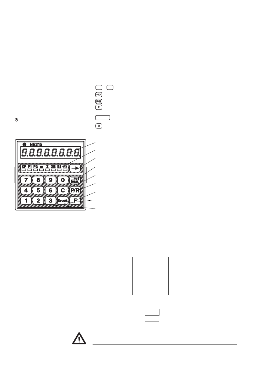
Components / LED-display
XP Counter status, main counter
P1 Preset value 1, main counter
P2 Preset value 2, main counter
m Meter display
Σ Totalizing counter
B1 Preset value, sec. counter
Current value, time meter
Control panel
0
...9Numerical keypad
Selector key for function display
Selector key for programming/operating mode
Function key
Druck
The counter is a micro-processor controlled electronic device with
serial interface for counting, controlling and monitoring. The device is
approved by the German Physical Technical Authorities (PTB) as
calibrated for the use as: “measured value transfer device for
application in calibrated machines for length measurement”.
Key for printing
Reset key
Function display
LEDs- Symbol display
Selector key/Function display
PTB-Number
Reset key C
Selector key for programming/operating mode
Function key
Key for printing
Numerical keypad
Address for printer:
DATAMEGA Mikrodatent. GmbH
Landsberger Str. 318-320
80687 München
Tel.: +49 (0)89 56017-300
4
Registration From Reference number
NE215 23.12.1993 1.62-3251.11 / IVO-040293
1. addendum 16.03.1995 1.62-3251.11 / IVO-040293
2. addendum 28.09.1997 1.62-3251.11 / IVO-040293
3. addendum 24.06.1999 5.23-99037480
4. addendum 29.03.2001 5.21-01028291
PTB-Approval:
The counter is only PTB approved in combination with an encoder.
The PTB- approved system for example provides a chart printer
model STAR SP298.
1. 3
93.15
Page 5
Getting to know the counter
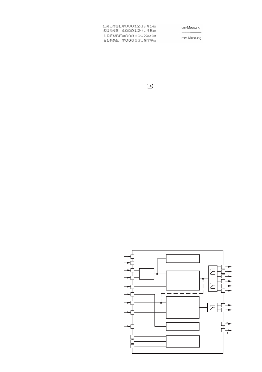
Example for print
NE215
Main counter systems: (PTB-approved)
1 up/down preset counter with totalizer.
Batch counter systems: 1 preset counter, adding.
A key provided at the counter enables switching the display to the
respective counters of the main respectively batch counting
system.
Counter function
Applications
The counter is administrating the inputs of both counting systems
and will react by the programmed output action upon achieving the
set presets respectively limit values.
Thanks to various programming options the device is capable of
many machine monitoring and controlling tasks. Running values and
the set parameters remain even after power failure.
The serial interface allows printout of counter values.
● Interior use for monitoring and control of production machines
and systems.
● In any branches of industry where length measurement is
subject to calibration.
The device must not be used in: explosive areas, medical appliances
as well as in applications explicitly mentioned in the standards of
VDE 0411 part 100.
2.1 Block diagram
The block diagram shows the components together with its contacts
and connections.
Supply
voltage
count
XP-Reset
h counter
B1 counter
B1 reset
2
3
12
A
B
A 90° B
13
14
15
16
17
Totalizer
Main counter
Batch counter
or
Tachometer
4
5
P1
6
7
8
P2
9
10
B1
11
Coding
Interface
19
18
T
23
R
25
GND
26
Time Meter
Interface
RS232
Sensor
supply
20
5
Page 6
Counter connect
NE215
3 Counter connect
This chapter will explain how the contacts are assigned.
Under chapters 3.1 to 3.5 you will find actual tips and technical data
for the various connections.
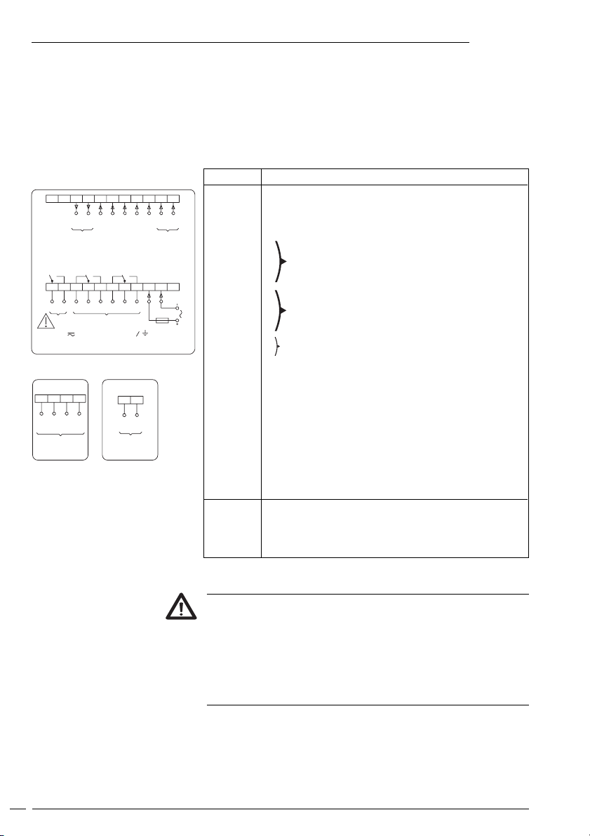
The electrical inputs and outputs are assigned to two 12-pole plug-in
screw terminals, coded to prevent reversed polarity.
Assignment
22 2 1 20 19 18 17 16 15 14 13 12
+24V 0V
Sensor
supply
NPN Br. 18-20
PNP Br. 18-19
B1 reset
11 10 9 8 7 6 5 4 3 2 1
B1 P2 P1
Output
max. 250 V Terminal - Terminal - Terminal
* Models with scaling
26 25 24 23
RxD
TxD
GND
RS232
B1 counter
22 21
T, R +
RS485
(Scaling on)*
XP reset
h counter
T, R -
BA
Count
Contact Function
1 Not assigned
2 Supply voltage
3 Supply voltage
4
5
6
1 Relay contact output P1
7
Supply
8
9
10
11
1 Relay contact output P2
1 Relay contact output B1
12 Signal input, track A
13 Signal input, track B
14 Reset XP
15 Time meter
16 Signal input, track B1
17 Reset B1
18 Coding input for input logic
19 Encoder supply 0 Volt
20 Encoder supply +24 Volt
21 Option RS485 T,R22 Option RS485 T,R+
23 Option RS232 TXD
24 25 Option RS232 RXD
26 Option RS232 GND
Litz contact only by means of connector sleeves with insulating
enclosures for reasons of shock protection according to VDE 0411
part 100. Do not otherwise assign contacts that have been left
unassigned ex factory. We recommend to screen all encoder
terminal leads and to ground the shield on one side. Shields on
both sides are recommended in case of RF interference or in case
of equipotential bonding over long distances. The encoder leads
should not be in the same phase winding as the MAINS supply and
the output contact leads.
6
Page 7
Counter connect
115 VAC 230 VAC
6 5 47 8 9
NE215
3.1 Connecting the power supply
For power supply following voltage ranges are available:
AC 115/230 VAC (50/60 Hz)
DC 24 VDC ±10%
Voltage supply Recommended external fuse
115/230 VAC M 125 mA
24 VDC M 400 mA
➜ Assign voltage supply to terminals 2 and 3 according to
diagramm.
DC-voltage 24 VDC:
Connect voltage supply that is free from any interference. Do not utilize the voltage supply for parallel supply of drives, shields, magnetic
valves, etc. Supplying lines must be separated from lines providing
load current.
Fire protection: Operate the instrument using the recommended
external fusing indicated in the terminal diagram. EN 61010 specifies
that 8 A/150 VA (W) must never be exceeded in the event of a fault.
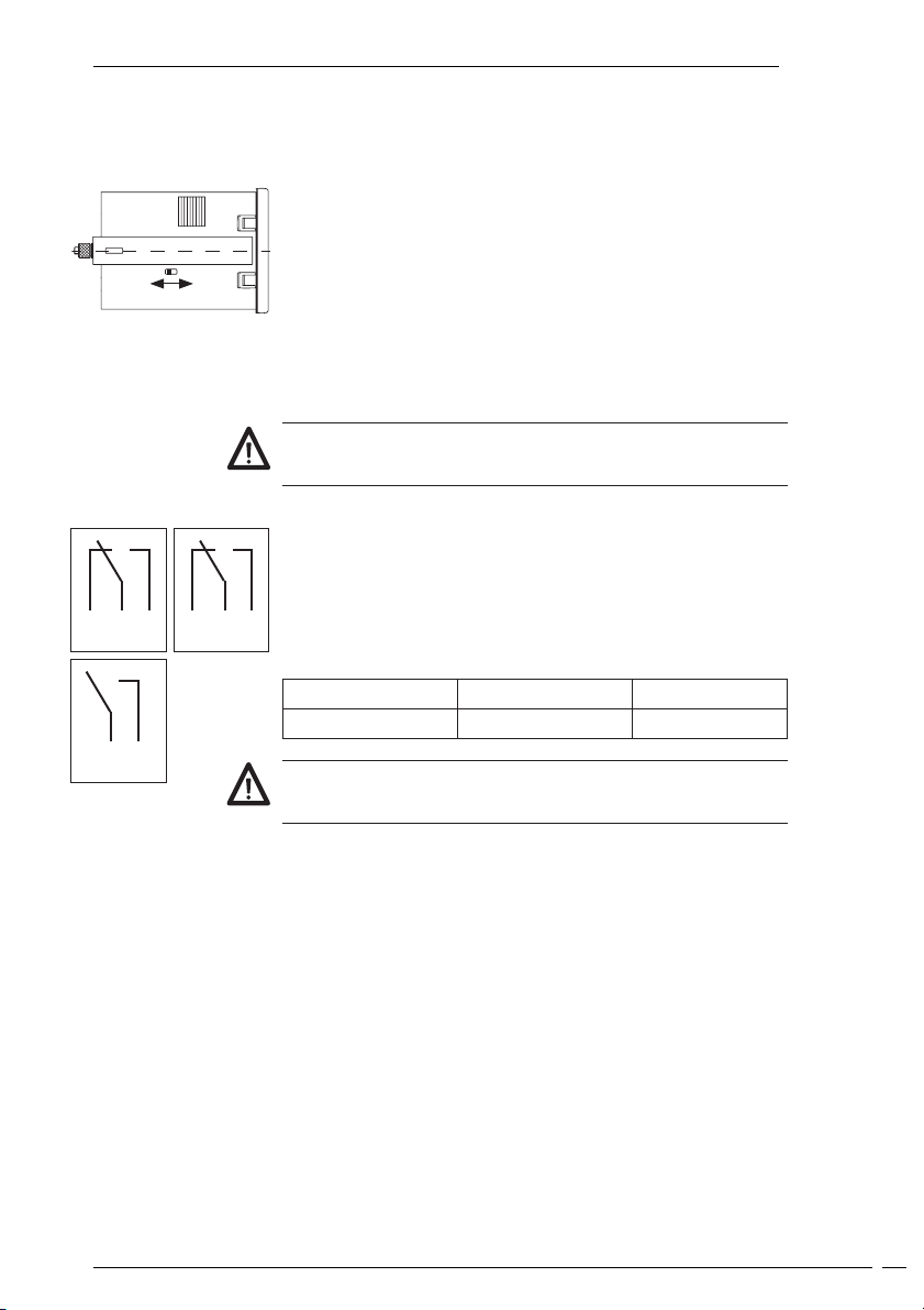
3.2 Assignment signal output „relay contact“
Terminals 4, 5, 6 and 7, 8, 9 are no-potential changeover contacts.
Terminals 10 and 11 are configured as NC or NO contacts in accordance with the purchase order specification. The signal outputs
can be assigned in accordance with the adjoining wiring diagram.
Implementation as a pulse or continuous signal, together with the
pulse time, is effected in the programming mode (lines 31, 32, 33).
11 10
Max. rating Max. voltage Max. current
150 VA/30 W 265 V 1 A
The user is responsible for ensuring that a switching load of 8 A/150
VA (W) is not exceeded in the event of a fault. Internal spark suppression by means of two zinc oxide varistors (275 V).
➜ Assign terminals 4, 5, 6; 7, 8, 9; and 10, 11 (relay contactoutputs)
accordingly.
7
Page 8
Counter connect
20 19 18 17 16 15 14 13 12
18 and 20
NE215
3.3 Assignment the signal inputs
Terminals 12 to 17 are AC optocoupler inputs. Terminals 12 (track A)
and 13 (track B) are pulse inputs for the main counter (XP) counting
function.
Terminal 14 is an external reset input for the main counter.
Depending on what is set in the programming mode (line 40),
terminal 15 serves as a starting input for the operating hours counter.
Terminal 16 (track B1) is the pulse input for the secondary counter
(XB). Terminal 17 is the input for resetting the secodary counter.
Programming input logic
Terminal Input Starting current Abschaltstrom
resistance
12 1,65 Kohm > 9 mA, < 16 mA < 0,5 mA
13 1,65 Kohm > 9 mA, < 16 mA < 0,5 mA
14 3,3 Kohm > 5 mA, < 8 mA < 0,5 mA
15 3,3 Kohm > 5 mA, < 8 mA < 0,5 mA
16 1,65 Kohm > 9 mA, < 16 mA < 0,5 mA
17 3,3 Kohm > 5 mA, < 8 mA < 0,5 mA
The main counter (XP) is reset by pplying an external signal (signal
width ≥ 30 ms) at terminal 14; the secondary counter (XP) at terminal
17. While an external signal is present, no counter take place. The
method of resetting is set in the programming mode (lines 29, 30).
Assign terminals 12 to 17 accordingly. The maximum counter
frequency is selected in the programming mode (line 26).
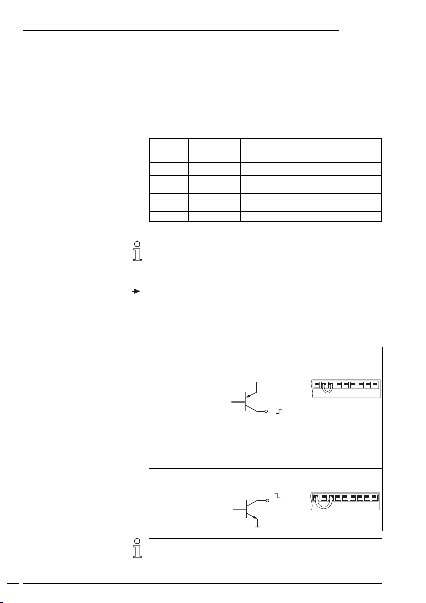
The signal input logic can be programmed by means of a bridge between terminals 18, 19 and 20, in accordance with the table below.
Apply
- if encoder supply
is not provided by
the counter.
- if the encoder is
featuring push-pull
or PNP output
- if several counters
are triggered in a
parallel way by one
encoder
Encoder signals
PNP, triggered by
positive signals.
E
B
K
Pin assignment
18 and 19
18 and 19
20 19 18 17 16 15 14 13 12
8
- if the encoder is
featuring a NPN
output.
NPN, triggered by
negative signal.
B
K
E
18 and 20
Electrical isolation is provided for instruments with an AC power
supply and a relay output without interface.
Page 9

Counter connect
NE215
3.4 Connecting the encoder supply
Connect the encoder supply at terminals 19 and 20.
Do not use the encoder supply to supply non-earthed inductive or
capacitive loads.
The encoder power supply is not short-circuit proof.
Terminal Voltage Max. Max. permissible
19 0V ––
20 +24 VDC Depending on load 80 mA
3.5 Interface connect
The serial interface is capable of executing the following functions:
– Data printout
Interface parameter are as follows:
– Data transmission rate (baud rate),
– Parity bit,
– Number of stop bits,
The interface parameters can be set in the programming
(lines 43, 44, 45 and 46).
The following interfaces can be connected to the counter:
– RS232
Interface characteristics
RS232
Transmission with the following characterisics:
– Asymmetric
– Two leads
– Point-to-Point connection - 1 transmitter and 1 receiver
– Max. data transmission distance: 30 m
+10 %/-50 %
residual ripple current
9
Page 10
To start test
NE215Counter connecting and operating
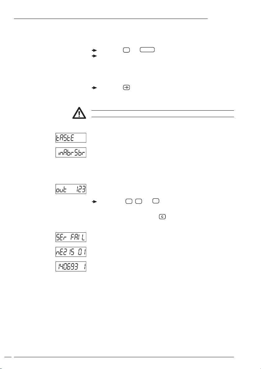
3.6 Executing the test routine
The test routine is described below.
Press the 2 and
Switch the counter on.
● All the display segments will be displayes automatically in
sequence and are therby tested for functional capability.
Druck
key simultaneously.
Test extension
Using the key, test the keyboard, the inputs, outputs and
interface in sequence.
No machine fuctions may connected when the outputs are tested.
Keyboard test
Input test
● Inputs can be triggered simultaneously or individually. A display
is only provided when a signal is applied.
Output test
Press keys 1, 2 and 3 .
The outputs are now activated.
Reset the outputs with the key.
Interface test
Display: Model and program number
Display: Program date and version
10
End of test
The test routine is terminated, the counter is now in the operating
mode.
Page 11
Operating mode
Operating mode
To read
Reset
To read
NE215
4 Operating mode
The operation and use of the counter are described in this section.
● As soon as the power supply has been switched on, the
counter is automatically set to the operating mode.
In the operating mode:
– the current main counter status can be read and reset;
– the preset values for the main and secondary counters can be
read;
– the current total can be read and reset;
– the current status of the secondary counter can be read and reset;
– the operating hours counter can be read.
All the parameters can be disabled in the programming mode.
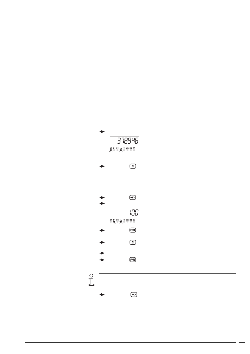
Main counter status
The current counter status is displayed in the operating mode;
no keying is necessary.
Readout running counter value.
Resetting must be enabled in the programming mode.
Press the key.
Main counter preset value
Resetting must be enabled in the programming mode
Press the key.
Read preset value P1.
To change
Other changes
Press the key.
● LED P1 flashes.
Press the key.
● Preset 1 is being deleted.
Input the preset value P1 via the numerical keypad.
Press the key.
● The change is completed.
If a key is not operated within 15 seconds, the preset value will
automatically be re-displayed in the operating mode.
Press the key.
● The following values can also be changed.
11
Page 12
Operating mode
NE215
If other values are changed, the value at witch the operating level
was left can be re-displayed with the key after the
programming mode has been left.
Other changes
To change
Other changes
To read
Press the key.
● Read preset value P2
Press the key.
● LED P2 flashes.
Press the key.
● Preset 2 is being deleted.
Input the preset value P2 via the numerical keypad.
Press the key.
● The change is completed.
If a key is not operated within 15 seconds, the preset value will
automatically be re-displayed in the operating mode.
Press the key.
● The following values can also be changed.
If other values are changed, the value at witch the operating level
was left can be re-displayed with the key after the
programming mode has been left.
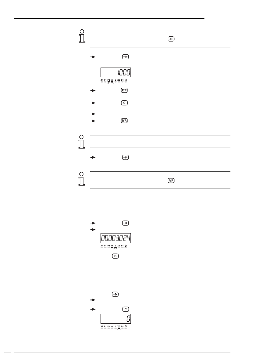
Totalizing counter
The totalizing counter can be disabled in the programming mode.
Press the key.
Read the totalizing counter.
12
Reset
To read
Reset
Press the key.
Secondary counter status
The secondary counter can be disabled in the programming mode.
Press the key.
Read off the current limit value secondary counter status
Press the key.
Page 13

Operating mode
To read
NE215
Secondary counter preset status
Press the key.
Read the secondary preset value.
To change
Other changes
To change
Press the key
● LED B1 flashes.
Press the key.
● Preset value of the batch counter is being deleted.
Input the new secondary counter preset value via the numerical
keypad.
Press the key.
● To change is completed.
If a key is not operated within 15 seconds, the preset value will
automatically be re-displayed in the operating mode.
Press the key.
● The following values can also be changed.
If other values are changed, the value at witch the operating level
was left can be re-displayed with the key after the
programming mode has been left.
Time meter
The time meter can be disbled in the programming mode.
Press the key.
Read the time meter
Press the key.
13
Page 14

Programming mode
Programming segment 1
Programming segment 2
Programming segment 3
Programming segment 4
To access programming
NE215Programming mode
5 Programming mode
This section describes the procedure for programming the counter.
Operating parameters are set in the programming mode, which is
subdivided into four programming segments.
In the first programming segment, all the operating parameters
can be accessed and changed. The operating parameters which are
disabled in the operating mode are also displayed here. The first
programming segment consists of 8 lines.
In the second programming segment, the individual operating
parameters for access to the operating mode can be disabled and
enabled. In the first programming segment, access is possible to
these disabled operating parameters.
In the third programming segment, all the machine-related
functions and values can be programmed.
In the fourth programming segment, the interface parameters can
be programmed.
Keying
The same key assignments apply to the individual programming segments. Since key functions may vary in the operating and programming modes, however, all the functions are described in full below.
Function in operating and
programming modes
Function in operating and
programming modes
Function in operating and
programming modes
Function in the operating mode
Function in the programming mode
Function in the operating mode
Function in the programming mode
14
Key
Transfer to the next operating parameters in the operating and
programming modes. For a fast run-through, hold the key down.
Key
Transfer from programming to operating mode and vice versa.
Keys 0...
Change of values via the numerical keypad.
Key
Deletes the display. Reset of possible programmed operating
continuous contacts.
Deletes the display. Reset of possible programmed operating
continuous contacts. Selection of output signals on continuous
signal (latch).
Key
Transfer from any display to a parameter corresponding the selection
in line 35.
In conjunction with the key, transfer to programming mode.
9
Page 15

NE215Programming mode
Function in the operating mode
Function in operating and
programming modes
In correct code
Correcter code unkown
Key for printing
The simultaneous operation of the Key for printing an the 2 key
starts the test routine; the power supply must be switched on at the
same time.
Printout release of the main counter.
The method of accessing the programming mode is described
below, together with the four programming segments in the order in
which they are used.
To access programming
Press the key.
● The system transfers from the operating to the programming
mode.
Press the key.
● is displayed. The code applies to programming
segments 1 - 4.
Input code.
Press the key.
No code is entered before delivery.
If an incorrect code has been input:
● appears in the display when the key is pressed.
● The counter reverts to the operating mode.
Press the key.
Press the key.
Input the correct code.
If the correct code is not known:
Return the counter to the factory.
When the correct code has been input, press the key.
● Now the programming lines are being called off one after the
other.
Druck
15
Page 16

Programming mode
NE215
Programming segment 1
Information on the displays and changing individual values is also
given in Part 4.
Press the key again.
● The operating parameters are now called up. The respective
LED flashes.
To changing operating parameters
Line 1
Line 2
Line 3
Line 4
Line 5
Line 6
Input the new values via the numerical keypad.
XP - Current counter status
P1 - Preset value 1
P2 - Preset value 2
Σ - Totalizer
XB - Secondary counter status
B1 - Secondary counter preset value
The LED display below
the meter symbol “m” is
always active with
length measurement
parameters.
16
Line 7
- Time meter
● At the conclusion of the first programming segment, a broken
line appears in the display.
Page 17

To change status
NE215Programming mode
Programming segment 2
In the second programming segment, the message STAT appears in
the display, signifying status selection.
● appears in the display. The LED for the corresponding
operating parameter flashes.
Significance of status numbers
0 Full access for operator (read and alter parameters).
1 Restricted access for operator (read parameters only).
2 None access for operator (No altering, no reading of parameters).
Input the appropriate status number.
● The changed status will automatically be stored when the next
programming line is selected.
Press the key again.
● The status of each individual operating parameter is called up in
sequence.
Line 1
Line 2
Line 3
Line 4
Line 5
Line 6
Line 7
XP - Main counter status
P1 - Preset value 1
P2 - Preset value 2
∑ - Totalizer
XB - Secondary counter status
B1 - Secondary counter preset value
- Time meter
● At the conclusion of the first programming segment, a broken
line appears in the display.
The default operating parameter status is zero.
17
Page 18

Programming mode
NE215
Programming segment 3
Programming segment 3 begins with programming line 21.
14 programming lines are displayed in sequence in these segments.
Default settings are always printed with * .
Line 21
Line 23
Line 26
Line 30
Line 31
Line 32
Operating modes
0 * Step preset
1
P1 Self-adjusting preset
Multiplier, secondary counter
1 * 1
2
2-99
Frequency, secondary counter XB
0 * 10 kHz
1
25 Hz
2
15 Hz
Reset secondary counter
0 * Autom. reset and external static
1
Autom. reset and external differential
2
External static
3
External differential
Output time P1
00.00 * Data in Sec. (Tol. -0.01 s, range 00.02 -99.99 s)
00.25 0.25
99.99
Maximum puls time
LAtch
Latch= continuous signal
Output time P2
00.00 * Data in Sec. (Tol. -0.01 s, range 00.02 -99.99 s)
00.25 0.25
99.99
Maximum puls time
LAtch
Latch= continuous signal
18
Line 33
Line 34
Line 35
Output time B1
00.00 * Data in Sec. (Tol. -0.01 s, range 00.02 -99.99 s)
00.25 0.25
99.99 Maximum puls time
LAtch Latch= continuous signal
Accept presets P1, P2 and B1
0 * On reset
1
Effective immediately
Adresses for function key
0 * No function
1 Any parameter selection
:
8
Page 19

NE215Programming mode
Line 36
Line 37
Line 38
Examples
Secondary counter functions XB
0 * External
1
Internal
2
Tachometer
Pulses per unit of measurement, as tachometer
1.0 0 * 1, 00
0,01 - 9999.99
Input of time measurement in seconds (s)
0 * Time base 1 s
1
Time base 2 s
2
Time base 3 s
3
Time base 6 s
4
Time base 10 s
5
Time base 20 s
6
Time base 30 s
7
Time base 60 s
The time base must be selected in accordance with the pulse
rate.
Pulses per rev. Time base in seconde
≥ 60 pulses/rev 1 s
< 60 ≥ 30 pulses/rev 2 s
1 pulses/rev 60 s
to to
Line 40
Line 41
Function input time meter
0 *
Operating hours with supply
1 Operating hours on/off
Code setting
0 *No code
1 -9999
● At the conclusion of these programming lines, a broken line will
appear in the display, signifying the competion of the third
programming segment.
on/off
19
Page 20

Programming mode
NE215
Programming field 4
Line 43
Line 44
Line 45
Line 46
To leave programming mode
Baud rate
0 * 4800 baud
1 2400 baud
2 1200 baud
3 600 baud
Parity
0 * Even parity
1 Odd parity
2 No parity
Address
* 0
1-9 9
Stop bits
0 * 1 Stop bit
1 2 Stop bits
● At the conclusion of these programming lines, a broken line will
appear in the display, signifying the competion of the fourth
programming segment.
Press the key.
● Counter now reverts to the operating mode.
20
Reprogramming the counter
to the defaults settings
Step preset
P1- Self-adjusting preset
Switch on the instrument and press the key simultaneously.
● All the programmed values will now revert to their defaults
settings.
5.1 Operating modes
The operating modes are described below.
On reaching a preset value, the counter continues to count to the
next preset value. Preset values are always processed in the
sequence: preset value 1, preset value 2. Any values can be chosen.
External or manual resetting can be carried out at any time.
Preset value P1 serves as a preliminary signal and functions as a
self-adjusting preset. The preliminary signal always switches to the
input value before the final signals is given. Any second preset value
can be chosen.
Page 21

Track A
Track B
RESET
VW (P2)
VW (P1)
O (SC)
OUT P1
OUT P2
NE215Programming mode
5.2 Counting modes for the main and totalizing counter
Up/down counting with two counting signals, phase-offset by
90 degrees
The counting direction is automatically identified from the leading/
lagging 90o phase offset.
The internal phase discriminator performs the necessary evaluation.
5.3 Output responses (Output Modes)
Signal output response is determined by the following:
– Programming of the preset value, output time, output logic and
output function;
– external resetting;
– external counting direction control.
The diagrams belows show the output signal responses.
Adding operating mode
Step preset with continuous signal, without automatic reset
RESET
SC
VW (P1)
VW (P2)
OUT P1
OUT P2
RESET
VW (P2)
O
(SC)
OUT 1
OUT 2
VW (P1)
Adding operating mode
Step preset with pulse signal, without automatic reset
Adding operating mode
Self-adjusting preset with pulse signal, without automatic reset
Input of the preset value P1 corresponds to the interval between the
preliminary signal and the final signal. This means that, if the final
signal (i.e. preset value P2) is changed, the preliminary signal is
automatically readjusted.
Tw
Tw
21
Page 22

Technical data
NE215
6 Technical data
Display 7-segment-LED display
Digit height 7,6 mm
Power supply As per purchase order
Power consumption 7 VA, 6 W
Encoder power supply 12...26 VDC, max. 80 mA
Optocoupler inputs NPN, PNP
Max. counting frequency 15 Hz, 25 Hz for XB
Data storage > 10 years
Mounting With clamping frame
Dimensions DIN-housing 72 x 72 mm, housing for front panel mounting
Mounting depth 100 mm
Core cross-section max 1,5 mm
Housing material Polycarbonate black, UL 94V-0
Weight AC version: approx. 450 g
Ambient temperature 0...+50 oC
Storage temperature -20...+70 oC
Relative humidity Max. relative humidity 80%, at 25 °C, not-condensing
General rating EN 61010 part 1
Interference immunity EN 50082-2
Emitted interference EN 50081-1
Max. speed Measuring in mm 600 m/min
Max. speed Measuring in cm 6000 m/min
8-digit, red
with minus sign
10 kHz für XP
2
DC version: approx. 320 g
- Protection class II
- Overvoltage protection category II
- Contamination factor 2
22
Page 23

72
6.1 Dimensions and cutout size
Sealing screw
NE215Technical data
105
100
10
Packing
72
75 min.
75 min.
68 +0,7
67.7
1-6
7
68 +0,7
Cutout
68 + 0.7 x 68 + 0.7 mm
6.2 Default settings
The following parameters are programmed into the counter by the
factory prior to delivery:
Preset value, main counter P1 100
Preset value, main counter P2 1000
Preset value, secondary counter B1 10
Secondary counter multiplier 1
Display Depending on the model with
either 2 or 3 DP
Pulse signal time
main/secondary counters 0.25s
Counting mode 1 (step preset)
Preset change the new preset becomes
active after reset.
Input function, secondary counter External triggering
Counting frequency,
secondary counter 10 kHz
Error messages
6.3 Error messages
and : Fault must be rectified by the factory.
: Excessively fast sequences, i.e.
inadequate intervals between presets
at high counting frequency.
● Error messages and can be cleared with the
key.
23
Page 24

NE215Open interface description
7 Open interface description
7.1 General information
The open interface is of the RS485 type. It is possible to send the
commands documented in the „Description of the Open Interface“
for remote control to the counter. The interface allows to call up data
and to change the programming of parameters not relevant for the
values to be calibrated.
In general, the counter is operated via the serial interface on a
personal computer – that is why the external device will be called PC
for short in the following. However, it is also possible to use another
device with similar features.
7.2 Transmission protocol
Transmission is effected character by character in ASCII code. Each
character consists of 8 bits. The 8th bit is the parity bit; in case of „no
parity“, the 8th bit will always be transmitted as a zero. The counter
responds to every request of the PC via the serial interface – if data
have been transmitted correctly.
The transmission of characters is introduced by the start-of-text character
<STX> and closed by the end-of-text character <ETX>. In addition, the
tachometer also sends a <CR> (carriage return) after the character
<ETX>. This allows the input (in high-level languages such as BASIC) of a
complete record of data with only one command. The character <STX> is
followed by an address allotted to the counter. This allows a target
approach of the counter in a serial network. The address is followed by
the indication of the line (position) that is to be read out or programmed.
In case of a programming instruction, the line indication is followed by a
„P“ (program) and the data (parameters).
24
The protocol is split into three groups, as described in the following:
a) Reading of storage locations (READ instruction):
<STX> Address Line <ETX> [<CR>]
b) Programming of storage locations (WRITE instruction):
<STX> Address Line P [VZ] Data <ETX> [<CR>]
c) Special commands:
<STX> Address Parameter <ETX> [<CR>]
<STX> Start of Text (02Hex)
Address 00..99 (device address)
Line 01..XX (please refer to operating plan)
P Programming command
D Print command
VZ Plus/Minus sign, only indicated if value
is negativ
Data Programming data
Parameter Special commands
<ETX> End of Text (03Hex)
<CR> 0DHex (Control character „carriage return“).
„CR“ needs not be indicated (optional),
will however, always be returned by
counter.
Page 25

NE215Open interface description
Important
The blanks between the particular characters of the commands
only serve the purpose of better legibility. The input at the PC must
be effected without blanks. Control characters (less than 20Hex) are
set in „pointed“ brackets. If a false protocol has been sent by the
PC, the counter will return an error message. Please read the
paragraph regarding error messages on page 29 under 7.7.
7.3 Reading of storage location
All storage locations that are indexed with a line number in the
programming scheme (except the separating lines that are indexed
dashes) can be read out. The protocol: <STX> Address line <ETX>
[<CR>] can be used for each line. The return answer of the counter
may vary in the protocol length from one line to the other. This
depends on the data length of the individual storage locations.
The counter can also be read out if operated in the RUN mode as
well as in the PGM mode. The only difference is that the return
answer of the counter will contain an „R“ or a „P“ in the mode
parameter, as described in the following.
Answer to a Read instruction (general):
<STX> Address Line Mode VZ Data <ETX> <CR>
Mode P = Counter is in Programming mode
R = Counter is in RUN mode
VZ Plus/Minus sign, only indicated if value is negative
Data Max. number of digits, with leading zeros w/o
decimal point.
7.3.1 Examples for the reading of storage locations
The following statement applies for the subsequent examples:
Counter address = 35; Counter mode = R (RUN mode)
Readout of preselection counter XP (Line=01, Count=-15.00)
Polling: <STX>3501<ETX>
Answer: <STX>3501R-00001500<ETX><CR>
Readout of operating mode (Line=21, Setting=Pos. 1)
Polling: <STX>3521<ETX>
Answer: <STX>3521R1<ETX><CR> (1 corresponds to P1 trailing preselection)
Readout of output time P1 (Line=31, Setting=0,25s)
Polling: <STX>3531<ETX>
Answer: <STX>3531R0025<ETX><CR>
Readout of address (Line=45, Address=35)
Polling: <STX>3545<ETX>
Answer: <STX>3545R35<ETX><CR>
7.4 Programming of storage locations
All storage locations that are indexed with a line number according
to the programming plan, except for the separating lines (that are
indexed by dashes) and the lines 1, 5, 6 and 8, may be programmed.
25
Page 26

The protocol: <STX> Address line P [VZ] data <ETX> [<CR>]
can be used for each line. The answer of the counter that is returned
after every programming step is the same as for the readout of the
line.
All storage locations may, principally, be programmed during the
RUN mode in the programming mode.
Please refer to page 27 (under 7.5.2) to find out how to switch to the
PGM mode.
Programming command (general):
<STX> Address Line P [VZ] Data <ETX> [<CR>]
7.4.1. Examples for the programming of storage locations
The following statement applies for the subsequent examples:
Counter address = 35; Counter mode = R (RUN mode)
Programming of preselection P1 (Line=02, Preselection P1=12.50)
Command: <STX>3502P00001250<ETX>
Answer: <STX>3502R00001250<ETX><CR>
Programming of preselection P2 (Line=03, Preselection P2=50.00)
Command: <STX>3503P00005000<ETX>
Answer: <STX>3503R00005000<ETX><CR>
Programming of output time P3 (Line=33, Time=0.30s)
Command: <STX>3533P0030<ETX>
Answer: <STX>3533R0030<ETX><CR>
7.5 Special commands
In the case of special commands, we are talking about instructions
that do not refer to any line number, with the exception of the
commands „Clear count“ and „Output to printer“.
NE215Open interface description
26
7.5.1 Clear counts
The counts XP (line 1), totalizer (line 5), batch counter (line 6), and
operating time meter (line 8) can be cleared via this special
command. It concerns all lines that cannot be programmed. All other
lines, such as preselections, are cleared by programming the value
ZERO (as described under item 4).
The instruction to clear corresponds to a reset via the C key and/or to
an external reset if a reset input is available.
The response (answer) of the counter when clearing is the same as
when reading the corresponding line.
General: <STX> Address Line <DEL> <ETX>
Example: Clearing of preselection counter XP
Address=35, Line=01, Status=RUN mode
Command: <STX>3501<DEL><ETX> <DEL> = 7FHex
Answer: <STX>3501R00000000<ETX><CR>
Page 27

NE215Open interface description
7.5.2 Switch counter to PGM mode or RUN mode
This command allows you to switch the counter upon every call
between the PGM mode and the RUN mode.
The current line, as with the reading command on this line, will be
returned as an answer.
General: <STX> Address <DC1> <ETX>
Example: Address=35, Status=RUN mode, Current line = 1, Count=0.15
Command: <STX>35<DC1><ETX> <DC1> = 11Hex
Answer: <STX>3501P00000015<ETX><CR>
If the instruction is repeated, the program switches back to the RUN
mode.
Command: <STX>35<DC1><ETX>
Answer: <STX>3501R00000015<ETX><CR>
7.5.3 Read out counter identification
It is only possible to read the identification data. Two parameters
follow the address: the command parameter „I“ (for identification)
and the selection parameter „T“ (Type and programming number) or
„D“ (date and version) for the different identification data.
Readout device type and programming number:
Command: <STX>35IT<ETX>
Answer: <STX>35NE215 03<ETX><CR>
Command: <STX>35ID<ETX>
Answer: <STX>35160295 1<ETX><CR>
Address=35, Type=NE215, Programming number=03
Readout date and version number:
Address=35, Date=16.02.95, Versions number=01
7.5.4 Readout of counter identification
It is only possible to read the identification data.
Two parameters follow the address: the command parameter „I“ (for
identification) and the selection parameter „T“ (Type and program-
ming number) or „D“ (date and version) for the different
identification data.
General: <STX> Address E <ETX>
Example:
Command: <STX>35E<ETX>
Answer: <STX>35Error 7<ETX><CR>
Address=35, Status=Error mode, Error=7
7.5.5 Clearing the error message
This command allows to clear error messages appearing on the
counter display. It is only possible to clear the error message that
can be cleared via the C key on the device itself (e.g.: not Error 1 or
2). The contents of the current line will be returned as an answer.
Address=35, Status=Error mode, Error=7, Line=01, Count=25.00
Command: <STX>35<ACK><ETX> <ACK> = 06H
Answer: <STX>3501R00002500<ETX><CR>
27
Page 28

Open interface description
Example: 29.08.94 10:30:45
<Daten>:
<Data>: Up to 11 data at choice may additionally be sent to the counter,
Example: Data_Time=29.08.94 10:32:20
Printout: 29.08.94 10:32:20
Answer: <STX>3501D00022368<ETX><CR>
NE215
7.6 Output to the printer
The command parameter „D“ allows the initiation of the output of
the lines 01, 02, 03 and 05 to the printer.
7.6.1 Appearance of the printout
The printout comprises
- date and time that need to be sent along by the PC upon a print
command
- optionally further data, which the PC may send along
- the length measurement needing to be calibrated, indexed by the
sign * .
LENGTH*000123.45m
7.6.2 Printout of the XP values
The protocol addressed to the counter is as follows:
Counter address=35, Line=01, Count XP=000223.68
PC Command: <STX>3501D<Date_Time> <Data><ETX>
<Date_Time> must be given in the following format:
<TT.MM.JJ hh:mm:ss>
TT: Tag MM: Monat JJ: Jahr
hh: Stunden mm: Minuten ss: Sekunden
TT:Day MM: Month JJ: Year
hh: Hour mm: Minutes ss: Seconds
All values must be 2-digit values and the punctuation must be
observed. (The characters < bzw. > / < and/or > only serve the
purpose of indexing and should not be transmitted.)
which will then also be printed. The sign * should not occur,
otherwise it will be ignored by the counter, i.e. it will not be sent to
the printer.
Date and time serve the purpose of clearly allocating the printed
length measurement to the data of the PC. After printing, the
counter will automatically trigger a carriage return so that the length
indication will always stand on a separate line.
PC Command: <STX>3501D29.08.94 10:32:20<ETX>
LENGTH*000223.68m
The counter will only respond to the PC when all characters have
been sent to the printer. The protocol then returned will contain the
value emitted to the printer:
28
7.6.3 Error message
If the PC does not send the date and the time as described above,
i.e. date/time are not complete or the punctuation is wrong, there
will be no printout and the counter sends an error message to the
PC.
Page 29

Open interface description
Answer: <STX>3501D<CAN>4<ETX><CR>
NE215
7.6.4 Printout of the lines 02, 03: preselections P1 and P2
As these are not length measurements that need to be calibrated,
the value of the preselections P1 and P2 is not printed with the sign
*, and it is also not necessary that the PC sends Date/Time along.
Example: Counter address=35, Line=02, P1=1.00
Printout: 29.08.94 10:33:18
Answer: <STX>3502D00000100<ETX><CR>
Printout: 29.08.94 10:33:29
Answer: <STX>3503D00001000<ETX><CR>
Example: Counter address=35, Line=05,
Printout: 29.08.94 10:34:52
Answer: <STX>3505D00122368<ETX><CR>
Further data=29.08.94 10:33:18
PC Command: <STX>3502D29.08.94 10:33:18<ETX>
P1 1.00
Counter address=35, Line=03, P2=10.00
Further data=29.08.94 10:33:29
PC Command: <STX>3503D29.08.94 10:33:29<ETX
P2 10.00m
7.6.5 Printout of Line 05: totalizer Σ
The value of the totalizer is printed with the sign *. Similarly Date/
Time will have to be sent along as with the XP value, otherwise the
same error message will be returned.
Totalizer count Σ=001223.68,
Data_Time=29.08.94 10:34:52
PC Command: <STX>3505D29.08.94 10:34:52<ETX>
SUM *001223.68m
7.6.6 Printing via key [Print] / [Druck]
If you press the key [Druck] during operation and if the value of the
preselection counter XP, the preselection P1, the preselection P2 or
the totalizer Σ are displayed, then the value will be indexed with the
sign * as with the PC command for the counter XP (line 01) and for
the totalizer (line 05). There is no printout of any additional data.
7.7 Error messages during data transfer
If the PC sends a wrong data protocol to the counter (e.g.: line that
does not exist or letter instead of digit), then the counter will return a
corresponding error message to the counter. In order to still receive
an error message after an error, the control character <STX> and the
address must at least be correct. If this is not the case, the data
block received by the counter will not be considered, and the
counter will not respond to the PC. If the PC does not receive a
response after a request has been sent, i.e. not even an error
message, then a fatal error has occurred. This may be the case if the
control character <STX> or the address are missing and if the
interface parameter of PC and counter are not congruent. Should
these be correct, however, then it can only be a matter of a failure of
the hardware or of the data line.
29
Page 30

Open interface description
Example: Address=35, Line=09 (invalid line),
Error 1: Format error (<ETX> not at the right place). This
Error 2: Line (position) not available or separating line
Error 3: Parameter error (inadmissible values in the
Error 4: This error message occurs if the PC requests the
NE215
General structure of the error messages:
<STX> Address Line Status <CAN> Error number <ETX> <CR>
Error number=2 <STX>3509R<CAN>2<ETX><CR>
The two positions „Line“ and „Status“ will not occur with the
special commands.
Error description in particular:
error might happen, for example, if the data format
was not observed when programming (e.g.: when
programming the limit value, only 5 instead of 6
data positions are transmitted.)
protocol). This means, for example, that the limit
value consists not only of digits but also of other
inadmissible characters, or that a value given lies
outside the admissible range.
counter to print in the programming mode, if the
printout of any line except the lines 01-03 and 05
is to be initiated, or if the PC does not send Date/
Time or sends them in a wrong format. The counter
will not allow the value to be sent to the printer
and responds with an error mistake to the PC.
Example for a returned error message:
Address=35, Line=01, Error number=4
<STX>3501D<CAN>4<ETX><CR>
30
7.8 List of the control characters used
Control character Hex Decimal
<STX> 02 02
<ETX> 03 03
<ACK> 06 06
<LF> 0A 10
<CR> 0D 13
<DC1> 11 17
<CAN> 18 24
<DEL> 7F 127
Page 31

Open interface description
7.9 Operating Plan
Line Display Short description
01 Preselection counter XP
02 Preselection 1
03 Preselection 2
Not applicable
05 Totalizer
06 Batch counter
07 Preselection batch counter
08 Time meter
10 Separating line
11 Status of preselection counter XP
12 Status of preselection 1
13 Status of preselection 2
14 Not applicable
15 Status of totalizer
16 Status of batch counter
17 Status of batch counter preselection
18 Status of time meter
20 Separating line
21 Operating mode main counter
22 Not applicable
23 Scaling factor batch counter
24 Not applicable
25 Not applicable
26 Frequency batch counter counting input
27 Not applicable
28 Not applicable
29 Not applicable
30 Reset batch counter
31 Output time P1
32 Output time P2
33 Output time P3
34 Take-over of preselections P1, P2, P3
35 Address of function key
36 Function of batch counter
37 Impulses per unit of tachometer
38 Selection of time base for the tachometer functions
39 Not applicable
40 Operating time counter input
41 Code setting
42 Separating line
43 Baud rate
44 Parity
45 Address
46 Stop bits
47 Separating line
NE215
31
Page 32

Open interface description
7.10 Programming plan
Lines in
italic*
= Factory setting
NE215
Line 11-18 Status for line 11-18
0 * Parameter can be changed
1 Clearing and/or input disabled
2 Parameter is skipped
Line 21 Operating mode principal count system
0 * Progressive preselections
1 P1 Trailing preselection
Line 22 Not applicable
Line 23 Scaling factor batch counter
00 Minimum value
1 * Default value
99 Maximum
Line 24 Not applicable
Line 25 Not applicable
Line 26 Frequency batch counter counting
0 * 10 kHz
1 25 Hz
2 15 Hz
Line 27 Not applicable
Line 28 Not applicable
Line 29 Not applicable
Line 30 Reset batch counter
0 * Autom. reset and external static
1 Autom. reset and external differential
2 External static
3 External differential
Line 31 Output time P1, (P2), (P3), B1
00.00 Maintained contact (LAtcH displayed)
0.25 * Default value
99.99 Maximal value
Line 32 Output time P1, (P2), (P3), B1
00.00 Maintained contact (LAtcH displayed)
0.25 * Default value
99.99 Maximal value
Line 33 Output time P1, (P2), (P3), B1
00.00 Maintained contact (LAtcH displayed)
0.25 * Default value
99.99 Maximal value
Line 34 Take-over of preselection P1, P2, B1
0 * In case of reset
1 After input
Line 35 Address for function key
0 * Function key not connected
:
8 Maximum value
32
Page 33

Open interface description
NE215
Line 36 Function of batch counter
Line 37 Impulses per unit at tachometer
Line 38 Time basis for tachometer function
Line 39 Not applicable
Line 40 Function of time meter
Line 41 Code setting
Line 43 Baud rate
Line 44 Parity
Line 45 Device address
Line 46 Stop bit
0 * external
1 internal
2 Tachometer
00.00 Minimum value
1.00 * Default value
9999.99 Maximum value
0 * 1 secound
1 2 secounds
2 3 secounds
3 6 secounds
4 10 secounds
5 20 secounds
6 30 secounds
7 60 secounds
0 * Time meter is running
1 Time meter on / off
0000 * Code not active
:
9999
0 * 4800 Baud
1 2400 Baud
2 1200 Baud
3 600 Baud
0 * Even Parity
1 Odd Parity
2 No Parity
00 * Minimum value
:
99 Maximum value
0 * 1 Stop Bit
1 2 Stop Bit
33
Page 34

Supplement
NE215
8. Supplementary operation manual for
open and closed interface
(February 1994, Erg. 31.8.1994)
The addendum describes the interfaces and documents the
modifications of the Operating Instructions for the Counter regarding
the additional open interface. Corresponding to the 1st. addendum
to file number: 1.62-3251.11 IVO-040293 dated 16.03.1995.
8.1 The closed interface
The closed interface is of the RS232 type. It allows to send data that
can be calibrated to the printer. The interface parameters cannot be
modified and are to be set at the printer as follows: Parity off, 7 data
bits, 1stop bit, Baud rate: 4800 Baud. Configuration of the interface
data at the printer: DIL-switch 7 and 8 „ON“.
Features of the RS232 interface:
– asymmetric
– 3 lines
– Point-to-point connection: 1 emitter and 1 receiver
– Data transmission distance: max. 30 m
8.2 The open interface
The open interface is of the RS485 type. It is possible to send the
commands documented in the „Description of the open interface“
for remote control to the counter. The interface allows to call up data
and to change the programming of parameters not relevant for the
values to be calibrated.
Features of the RS485 interface:
– symmetric
– 2 lines
– Multipoint connection: Emitter and receiver (max. 32 devices)
– Data transmission distance: max. 1500 m
34
8.3 Modifications of the operating instructions
8.4 Modifications in Chapter 2: „Get to know your counter“
All indications regarding interfaces refer to the closed interface.
8.5 Modifications in Chapter 3: „Counter connection“
All indications regarding interfaces refer to the closed interface.
8.6 Modifications in Chapter 3.5: „Interface connection“
The closed interface:
Set the interface parameters as indicated under Chapter 1.1.
The contacts 23-26 are assigned to the closed RS232-type interface.
The open interface:
It is possible to choose the interface parameters as described in the
Operating Instructions under lines 43 - 46.
Interface parameters are:
- the speed of transmission (Baud rate)
- the parity bit
Page 35

Supplement
NE215
- the number of stop bit
The contacts 21(-T,R) and 22(+T,R) are assigned to the open RS485-type
interface.
9. Supplement to the scaling factor manual
(May 1999)
This supplementary manual is describing the modification of the
counter’s operation manual regarding application of the scaling factor
and the alibi printer SP 298 of the company Star. It is according to the
third addendum of licence No. 1.62-3251.11 file number 5.23-99037480
dated 24.06.1999.
Address for printer: DATAMEGA Mikrodatentechnik GmbH
Landsberger Str. 318-320
80687 München
Tel.: 089/56017-300
9.1 Modifications in Chapter 2: „Get to know the counter“
The counter consist of
- preset counter with 2 presets (PTB-approved) and scaling factor
- batch counter with preset and multiplier
- totalizer, (PTB-approved) with scaling factor
- hour counter
The device is approved by the German Physical-Technical Authorities
(PTB) for calibration. The PTB-approved register system provides a
printer model Star SP298 with serial interface RS232.
Printer DIP switch settings (for counters with closed interface):
Schalter 1 2 3 4 5 6 7
Off On Off Off Off Off On
Baudrate: 7 Datenbits gerade Parität Xon/Xoff 2K Puffer
4800 Bit/s
The settings correspond to the counter default parameters in programming lines 43 and 44. Upon any modifications the DIP switch
settings have to be adapted correspondingly.
Printer DIP switch settings (for counters with closed and open
interface):
Schalter 1 2 3 4 5 6 7
Off On Off On Off Off On
Baudrate: 7 Datenbits keine Parität Xon/Xoff 2K Puffer
4800 Bit/s
These settings are always valed since they cannot be altered in any
way at the counter.
35
Page 36

Supplement to the operation manual with scaling factor
9.2 Modifications in Chapter 3: „Counter connection“
New pin assignment for pin 15: scaling on.
9.2.1Modifications in Chapter 3.3: „Assignment of signal inputs“
Pin 15 is for activating the setting of the scaling factor (line 22
programming level). Prior to sealing the pins the setting of the
scaling factor is activated by the signal trigger “scaling on” (pin 15).
Activation is realized by connecting pins 15 and 20, by a bridge from
18 to 19 or by 15 to 19, if 18 has to be connected to 20 (refer also to
page 8 “programming of input logic” in the operation manual).
After having set the scaling factor, the connection to pin 15 has to be
removed. Once being sealed, this pin is no longer accessible and the
scaling factor is indicated in the programming level without allowing
any alteration.
9.3 Modifications in Chapter 5: „programming the counter“
The scaling factor of the main counter is shown in programming line
22. Any modification is only possible if pin 15 is being activated (see
above).
Programming line 22:
Line 22 Scaling factor main counter
1.0000 Default
0.0001 Scaling range 0,0001
99.9999 up to 99,9999
Programming line 40 “function of the hour counter input” is
obsolete. The hour counter is always active after “on”.
2 2 1.0 0 0 0
NE215
Scaling factor main counter
36
Page 37

Suitable encoder PTB-version
NE215
10. Suitable encoder
Technical Data
Model Incremental Encoder
RPM value 10.000 min
Supply Voltage 10...30 VDC, with reverse voltage protection
Input signals Push-pull, outp., short-circuit-protect.
Signal output Kanal A, B, N
Resolution Up to 500 Impuls
Current consumption Max. 60 mA (w/o load) for 24 VDC
Ambient temperature -20...+70 °C
Storage temperature -20...+100 °C
Protection to
Shaft w/o seal IP 54
Shaft with seal IP 65
Relative humidity Max. 95 %, not condensing
Endurance
Vibration IEC 68 part 2-6 ≤100 m/s2 / 16-2000 Hz
Schock IEC 68 part 2-27 ≤1000 m/s2 4 ms
Starting torque
w/o seal (IP54) ≤0,010 Nm
with seal (IP65) ≤0,015 Nm
Interference immunity EN 50082-2
EN 61000-4 - 2 to 4 Serverity grade 3
Emitted interference EN 50081-2
Shaft loading Axial < 20 N, radial < 40 N
Inertia torque 1,45 x 10⁻⁶ kgm
Housing material Aluminium
Weight Ca. 250 g
-1
2
Order designation
GPI0W.
Order Flange / Shaft
0 Clamping flange / 10 mm, mounting M3
1 Clamping flange / 10 mm, mounting M4
5 Servo flange / 6 mm, mounting M4
Voltage / Signals
10 10...30 VDC push-pull output A 90° B +0
Connection
12 Cable 2 m axial, Pg9
14 Cable 5 m axial, Pg9
16 Cable 10 m axial, Pg9
22 Cable 2 m radial, Pg9
24 Cable 5 m radial, Pg9
26 Cable 10 m radial, Pg9
Impuls
39 50 Imp./rev.
15 500 Imp./rev.
37
Page 38

Suitable encoder PTB-version
35
10 20
15
9.
ø 10h8
13
Level High > UB -3 V (with I = -20 mA)
Level Low < 1,5 V (with I = 20 mA)
Load High < 40 mA
Load Low < 40 mA
M3 / 5 deep
(M4 / 5 deep)
120°
NE215
Pin assignment
Assignment Cable color
A blue
B beige
0 green
UB brown
0V black
Output signals
Signals with clockwise sense or rotation when looking at the flange.
Track A
Track B
Zero pulse
Push-pull output (10...30 VDC)
Dimensions
GPI0W Clamping flange
16 3 5 10 20
15
38
9.
15
36f8
48 ±0.1
58
ø 10h8
GPI0W Servo flange
M4 / 7 deep
120°
42 ±0.1
50h7
58
16
15
10
4
41
9.
ø 6f8
5.5
3
3
16
13
10
4
41
9.
ø 6f8
5,5
3
3
Page 39

Models/order designation
Part number
NE215. 1 AX0
5 In cm, 9999.99
Display
50 pulses/rev.
w/o interface/RS232
6 In mm, 999.999
500 pulses/rev.
w/o interface/RS232
7 In cm, 9999.99
50 pulses/rev.
at RS232/RS485
8 In mm, 999.999
500 pulses/rev.
Voltage supply
2 115/230 VAC
3 24 VDC
at RS232/RS485
Outputs
1 Relay outputs, B1 normally closed
Interface
0 Without interface
1 RS232
2 RS232/RS485
39
Page 40

 Loading...