

Page 1

Operating Instructions
Interface Description
N 155 Target Display
Program 01
From version 2.10
Content Page
1. General information 2
1.1 Safety precautions 2
1.2 Description 3
2. Pin assignment 3
3. Interface 4
3.1 Interface data 4
3.2 Protocol 4
3.3 Check sum 5
3.4 Special features in data transfer 5
3.5 Broadcast commands 5
4. Description of commands 6
4.1 General information 6
4.2 Operating commands 6
4.3 Parameter commands and their significance 10
4.4 Identifier commands 13
4.5 Specific commands 14
5. Error signals 16
5.1 CRC error 16
5.2 Format error 16
6. Overview of commands 16
7. Technical data 17
Baumer IVO GmbH & Co. KG 03.10
Dauchinger Strasse 58-62 • DE-78056 Villingen-Schwenningen Subject to modification
Phone +49 (0)7720 942-0
www.baumer.com
• info.de@baumerivo.com
• Fax +49 (0)7720 942-900 in technic and design.
• 171.02.294/4
Page 2

N 155
1. General information
1.1 Safety precautions
General remarks
The equipment is designed and assembled according to the prevailing regulations of technology. The equipment
left the manufacturer in perfect working order and in line with all safety-relevant conditions. To maintain this
status of the equipment, it is imperative to stick to the following when installing and using the device:
- use only according to the intended purpose,
- observation of any precautions regarding safety and hazards,
- observe the present manual and especially the relevant safety precautions!
Make sure that the operating manual and especially the chapter describing the safety precautions is read and
well understood by the staff in charge. Supplementary to the operating instructions, ad other generally or legally
relevant regulations regarding accident prevention and environmental care are to be considered and observed.
This manual is a supplement to already existing documentation (data sheet, mounting instructions, catalogues).
Intended purpose of the equipment
Intended purpose of the equipment is industrial process monitoring and control in metal, wood, plastic, paper,
glass and textile etc. industry.
It is imperative that the equipment is applied only
- in properly installed condition and
- in line with the relevant technical data!
Any operation outside the technical specifications/parameters is improper use and in conjunction
with the equipment/processes/machines to be monitored/controlled might lead to
- fatal injuries
- serious damage to health,
- damage to property or corporate equipment or
- damage to the device!
Any overvoltage the device might be exposed to at its connecting terminals has to be limited to the values
stipulated in overvoltage category II (see technical data).
The device must not be operated
- in hazardous areas where is danger of explosion,
- as medical equipment or in medical areas,
- or in any applications expressly named in EN 61010!
If the device is utilized for control/monitoring of machines or processes where as the result of a
failure/malfunction or incorrect operation of the device might occur
- any threats to life,
- risks of damage to health or
- any risk of damage to property or environment
the corresponding appropriate safety precautions must be taken!
Do not open the housing of the device or proceed any modifications! Any modifications of the device can affect
operating safety and result in danger!
Do not proceed any repairs but return defective devices to the manufacturer!
Installation/commissioning
In case of any extraordinary incidents (including in the operating behaviour) that impair safety switch off the device immediately.
Installation must be carried out by suitably trained experts only. After proper mounting and installation the device
is ready for operation
Maintenance/repairs
Always disconnect the power supply of all appliances involved. Maintenance and repair work must only be carried out by suitably trained experts.
If troubleshooting is unsuccessful, do not continue using the device but contact the manufacturer.
.
www.baumer.com 2
Page 3
N 155
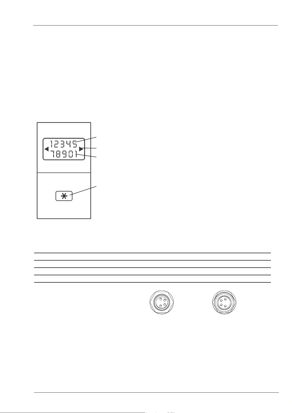
1.2 Description
Mounting the target display is by using the attached mounting plate that is fixed at the machine by using two
screws. The target display can be hooked onto the brackets provided at the mounting plate.
The position data will not get lost even in case of power failure (min. 10 years).
The current position value is indicated as running value in the two-line LCD display with backlight (2 x 5 digits,
numeric). Optionally the target received by the control unit (master) can be indicated simultaneously in the same
display. Two arrows show the editing engineer the turning direction in order to align current value with target. As
soon as the current value is in coincidence with the target and within the tolerance window, the target will disappear. Programming the relevant parameters at the master enables the display to be turned by 180° to allow vertical installation of the target display. Connecting the target display is by the help of an M8 connector. Power
supply of all target displays connected is by the same cable directly by master. Programming of target display by
master only.
target display
arrows indicating the direction
display „current value“
enter key
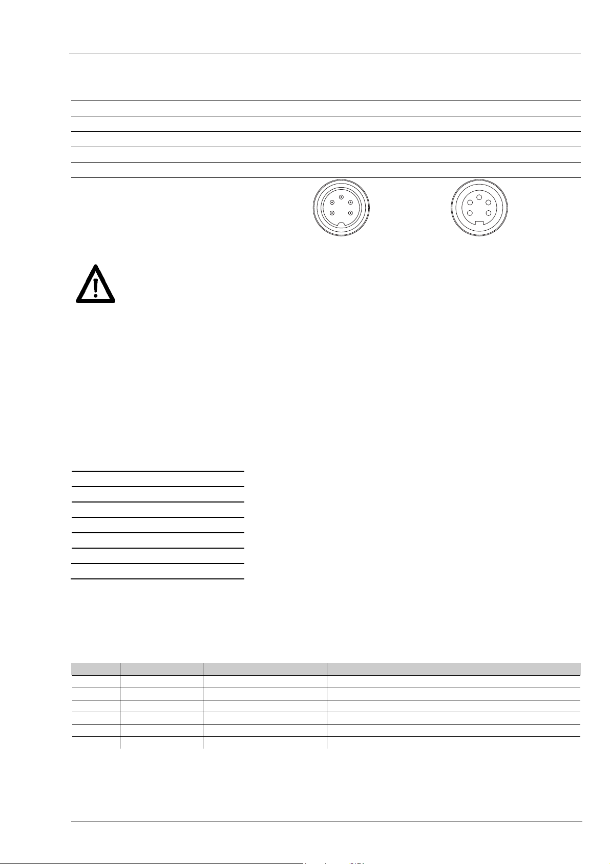
2. Pin assignment
Terminal Assignment Wire color DIN47100
Pin 1 Tx/Rx-, RS485 white orange
Pin 2 Tx/Rx+, RS485 brown brown
Pin 3 sensor supply +24 V yellow red
Pin 4 sensor supply 0 V green black
1
2
3
4
connector M8
IEC757
2
4
1
3
mating
connector M8
www.baumer.com 3
Page 4
N 155
Terminal Assignment Wire color DIN47100
IEC757
Pin 1 sensor supply +24 V yellow red
Pin 2 sensor supply 0 V green black
Pin 3 -- -- --
Pin 4 Tx/Rx+, RS485 brown brown
Pin 5 Tx/Rx-, RS485 white orange
3
4
2
1
5
2
1
connector M16
Connect power supply that is free from interference emission. The supply must not be used as
parallel supply of drives, shields, magnetic valves, etc.
Apply DC according to terminal assignment power supply: 24 VDC ±10 %
Shield
Use shielded cables only. The cable shield must be grounded at the machine
(two examples each depending on the cable, see drawings).
3
4
5
mating
connector M16
3. Interface
3.1 Interface data
Type: RS485
Baud rate: 19200
Parity: No
Data bits: 8
Stop bits: 1
Handshake: No
Check sum: Yes (CRC)
Lag time response*: 1...16 ms
3.2 Protocol
The target display operates with ASCII protocol (clear text protocol). Depending on the command, the volume of
the protocol varies between 5 and 17 bytes.
Byte Hex-Code Significance Value range
1 01H SOH = header token fix on 01h
2 XXh Adr = address 00...31dez + 20h Offset (address 00 = 20h)
3 XXh Cmd = command code defined commands
4-n [XXh..XXh] [Data] = data 20h-7Fh
n+1 04h EOT = footer token fix on 04h
n+2 XXh CRC = check sum 00h...FFh
* To avoid Bus collisions, a minimum time lag in responding of 1 ms
is imperative, i.e. the time elapsed between the last bit of the query
and sending the 1st bit of the N 155 response.
Important: Please consider that due to the abovementioned
minimum time lag of 1 ms in responding the Bus switching time
after having sent the last bit must not exceed 1 ms.
www.baumer.com 4
Page 5

N 155
3.3 Check sum
To support an error-free data transmission, a check sum byte CRC is added after the footer token (EOT) to the
string to be transferred. Upon reception of a command the CRC byte received is crosschecked with the selfcalculated CRC byte.
Algorithm:
1) Reset check sum byte.
2) Rotate check sum byte by 1 bit to the left.
3) Link result to first data byte XOR.
4) Rotate result by 1 bit to the left.
5) Link result to the second data byte XOR.
:
x) Rotate result by 1 bit to the left.
y) Link result to the last data byte (always 04H) XOR.
z) Add result as CRC after the footer token (04H) to the sending string.
Note:
1101 0000 RL 1010 0001 Important: Bit 7 is being shifted into bit 0 during rotation
Example:
Transmission string w/o CRC = 01h 20h 43h 04h
CRC-Byte = 0Ah
0000 0000 RL 0000 0000 XOR 0000 0001 (01h) = 0000 0001
0000 0001 RL 0000 0010 XOR 0010 0000 (20h) = 0010 0010
0010 0010 RL 0100 0100 XOR 0100 0011 (43h) = 0000 0111
0000 0111 RL 0000 1110 XOR 0000 0100 (04h) =
Legend: RL = rotate left; XOR = non-equivalence link
0000 1010
= CRC
3.4 Special features in data transfer
For reasons of compatibility and independent from the number of digits provided in the display, the complete
multicon system features the same data volume (refer to chart „overview of commands). For example, command “R” (read current value) comprises 6 bytes as data volume to be transferred whilst it is a 5-digit display
only.
3.5 Broadcast commands
Some specific commands are defined as so-called broadcast commands. As soon as such a command is sent
by master to identifier 99, the command will be accepted by each N 155 in the network. Each individual target
display will accomplish the respective function but will not return any confirmation to the master.
www.baumer.com 5
Page 6
N 155
4. Description of commands
4.1 General information
The following is describing the individual interface commands broken down into the four groups below:
- operating commands [ commands required during operation ]
- parameter commands [ commands serving for parameterization ]
- identifier commands [ commands for indication or alteration of the device identifier (address)]
- specific commands [ commands for specific functions as device reset or read version number]
The following abbreviations will be applied:
SOH = Start of header (header token)
EOT = End of transmission (footer token)
Adr = device identifier including offset 20h
Cmd = Command
data = data being sent or received
4.2 Operating commands
4.2.1 Read current value „R“ (52h)
This command is for reading the 5-digit current value (lower display line). Data volume is always 6 bytes. In case
of a negative value, the negative “-“ sign (2Dh) together with 5 data bytes will be returned. Positive values are
depicted by 6 data bytes without sign. Values of less than 5 (4) digits will come with preceding zeroes. Please
note that the current value is always of 5 digits (refer also to chapter “Special features in data transfer”).
Example 1: Read current value (current value = -32.50
Send
Response
Example 2 Programming the current value (new current value = 75.50)
Send
Response
4.2.2. Read / write target (profile) „S“ (53h)
This command is for reading the presently active target or for programming respectively reading a specific target. The data are composed of profile number (2 bytes) and target (6 bytes). Important: Negative targets are
transferred as 5 digit numbers (see example no. 3). Please consider that the targets are always of 5 digits only.
Example 1: Read active target (current profile number = 12; target = 12.50)
Send
Response
Response upon clearing all targets:
Response
SOH Adr Cmd EOT CRC
01h 20h 52h 04h 40h
SOH Adr Cmd current value = -32.50 EOT CRC
01h 20h 52h
SOH Adr Cmd current value = 75.50 EOT CRC
01h 20h 52h
SOH Adr Cmd current value = 75.50 EOT CRC
01h 20h 52h
SOH Adr Cmd EOT CRC
01h 20h 53h 04h 2Ah
SOH Adr Cmd Profil-Nr. = 12 target = 12.50 EOT CRC
01h 20h 53h
SOH Adr Cmd Profil-Nr. = FFh target = FFFFFFh EOT CRC
01h 20h 53h
2Dh 30h 33h 32h 35h 30h
30h 30h 37h 35h 35h 30h
30h 30h 37h 35h 35h 30h
31h 32 30h 30h 31h 32h 35h 30h
3Fh 3Fh 3Fh 3Fh 3Fh 3Fh 3Fh 3Fh
04h 54h
04h C9h
04h C9h
04h 3E
04h 2Ah
www.baumer.com 6
Page 7

N 155
Example 2: Read target of a specific profile (profile number = 17; target = 12.50)
Send
Response
SOH Adr Cmd Profil-Nr. = 17 EOT CRC
01h 20h 53h
31h 37h
04h 16h
SOH Adr Cmd Profil-Nr. = 17 target = 12.50 EOT CRC
01h 20h 53h
31h 37h 30h 30h 31h 32h 35h 30h
04h BCh
Example 3: Write target of specific profile (profile number = 17; target = -12.50)
s
Send
Response
SOH Adr Cmd Profil-Nr. = 17 target = -12.50 EOT CRC
01h 20h 53h
31h 37h 2Dh 30h 31h 32h 35h 30h
04h FBh
SOH Adr Cmd Profil-Nr. = 17 target = -12.50 EOT CRC
01h 20h 53h
31h 37h 2Dh 30h 31h 32h 35h 30h
04h FBh
4.2.3 Read / write profile number „V“ (56h)
This command is for reading the number of the presently active profile respectively for altering the profile.
Example 1: Read active profile (active profile number = 38)
Send
Response
Response after reset upon clearing all profiles:
Response
SOH Adr Cmd EOT CRC
01h 20h 56h 04h 20h
SOH Adr Cmd Profile no. = 38 EOT CRC
01h 20h 56h
33h 38h
04h 28h
SOH Adr Cmd Profile no. = FF EOT CRC
01h 20h 56h
3Fh 3Fh
04h 16h
Example 2: Send new profile (New profile number = 17)
Send
Response
SOH Adr Cmd Profile no. = 17 EOT CRC
01h 20h 56h
31h 37h
04h 3E
SOH Adr Cmd Profile no. = 17 EOT CRC
01h 20h 56h
31h 37h
04h 3E
Example 3: Send new profile by broadcast command to each N 155 (Adr = 99 (83h); new profile number = 17)
Send
SOH Adr Cmd Profile no. = 17 EOT CRC
01h 83h 56h
31h 37h
04h 04
Response No confirmation
To check whether the new profile has been entered by all N 155 in the network, check command „C“ (43h) can
be applied.
4.2.4 Check position „C“ (43h)
This command is providing the alignment status of target versus current value. If current value is in coincidence
with target the response will be „o“ (6Fh) for OK together with the current profile number. If the running value is
beyond the target, „x“ (78H) followed by the current profile number will be replied.
Example: (active profile number = 05)
Send
Response if current value = target:
Response
Response if current value ≠ target:
Response
SOH Adr Cmd EOT CRC
01h 20h 43h 04h 0Ah
SOH Adr Cmd Status Profile no. = 05 EOT CRC
01h 20h 43h
6Fh 30h 35h
04h A5h
SOH Adr Cmd Status Profile no. = 05 EOT CRC
01h 20h 43h
78h 30h 35h
04h 1D
www.baumer.com 7
Page 8

N 155
The following state-related values are available:
State Significance
o (6Fh) current value=target
x (78h) current value≠ arget
Extended command Check Position „CX“
Besides the state value of the target/current value comparison, the extended command „Check Position“ reads
out the current value. The profile number is not transmitted. Regarding available state-related values please see
above.
Example:
transmission
Response
SOH Adr Cmd
01h 20h 43h 58h 04h A8h
SOH Adr Cmd
01h 20h 43h
4.2.5 Read / write offset „U“ (55h)
This command is for reading or writing the offset to be added to the actual current value. This function however
has to be activated first in the command bit parameter ‚a’ (61h).
Example 1: Read offset
Send
Example 2: Write offset
Send
Response in both examples:
Response
SOH Adr Cmd EOT CRC
01h 20h 55h 04h 26h
SOH Adr Cmd data (offset = –20.00) EOT CRC
01h 20h 55h
SOH Adr Cmd data (offset = –20.00) EOT CRC
01h 20h 55h
4.2.6. Write a number sequence in upper line of the display „t“ (74h)
The command is for writing a 5-digit number sequence in the upper display line. The sequence is depicted without dot respectively comma. Preceding zeroes as well as both arrows for direction are hidden. The bottom line is
still showing the current value.
The number sequence will remain until any command except „t“, „u“ or „R“ is received by interface.
Example: (number sequence = 054321)
Send
Response
SOH Adr Cmd Number sequence = 054321 EOT CRC
01h 20h 74h
SOH Adr Cmd Number sequence = 054321 EOT CRC
01h 20h 74h
SCmd
EOT CRC
state
reserved reserved Current value = -12.50 EOT CRC
6Fh 80h 80h 80h 80h 2Dh 30h 31h 32h 35h 30h
2Dh 30h 32h 30h 30h 30h
2Dh 30h 32h 30h 30h 30h
30h 35h 34h 33h 32h 31h
30h 35h 34h 33h 32h 31h
04h C3h
04h C3h
04h C6h
04h C6h
04h B7h
www.baumer.com 8
Page 9

N 155
4.2.7 Write a number sequence in the lower line of the display „u“ (75h)
The command is for writing a 5-digit number sequence in the lower display line. The sequence is depicted without dot respectively comma. Preceding zeroes as well as both direction arrows are hidden. The upper line is still
showing the current target or number sequence.
The number sequence will remain until any command except „t“, „u“ or „R“ is received by the interface.
Example: (number sequence = 012345)
send
response
SOH Adr Cmd Number sequence = 012345 EOT CRC
01h 20h 75h
SOH Adr Cmd Number sequence = 012345 EOT CRC
01h 20h 75h
30h 31h 32h 33h 34h 35h
30h 31h 32h 33h 34h 35h
04h B6h
04h B6h
Important:
Combining the commands „t“ and „u“ enables a 10-digit number in the display.
Both number sequences are not saved by EEPROM.
www.baumer.com 9
Page 10

N 155
4.3 Parameter commands and their significance
4.3.1 Read / write bit parameters „a“ (61h)
To exploit the maximum storage capacity, several parameters are put together and transferred as “pack”.
Parameter codes as follows:
Data1: 1 0 X X 0 0 0 0
┬ ──┬── ───┬───
│ │ └───── reserved
│ └──────────── arrows 0/1/2/3 (UP/DOWN/UNI/OFF)
└──────────────── 1
Data2: 1 0 0 X 0 X 0 0
┬ ┬ ─┬─ ─┬─ ─┬─
│ │ │ │ └─── reserved
│ │ │ └─────── turn display 0/1 (OFF/ON)
│ │ └─────────── offset 0/1 (OFF/ON)
│ └────────────── reserved
└──────────────── 1
Data3: 1 0 X X X 0 X X
┬ ┬ ──┬── ┬ ─┬─
│ │ │ │ └─── hide target 0/1/2 (ON/OFF/EVER)
│ │ │ └────── resolution 0/1 (1/100 or 1/10)
│ │ └────────── decimal point 0/1/2/3/4/5 (AUTO/OFF/0.0/0.00
│ │ 0.000/0.0000)
│ └────────────── reserved
└──────────────── 1
Data4/5: 0 0 1 1 X X X X
───┬───
└───── reserved
Important: Only bits marked ‘X’ may be altered. The fix values „1“ and „0“ must not be altered since thereby a
control token (tokens < 20h) might be created what is not allowed in ASCII protocol.
Example 1: Read bit-parameters (Data1 to Data3 = 80h; Data4 to Data5 = 30h)
Send
Response
Example 2: Write bit parameters (positioning direction = Down; turn display = On)
Send
Response
Parameter significance
Arrows
This parameter is for displaying arrows intended as support for the editing engineer. They indicate the direction for
the new setting (clockwise or counter clockwise, up or down). The following settings are possible
00 = Up If current value < target: arrow at the right; current value > target: arrow at the left
01 = Down Similar to „Up“, but direction of the arrows the other way round
10 = Uni If current value ≠ target: always indicate both arrows
11 = Off Arrows always hidden
SOH Adr Cmd EOT CRC
01h 20h 61h 04h 4E
SOH Adr Cmd Data1 Data2 Data3 Data4 Data5 EOT CRC
01h 20h 61h
SOH Adr Cmd Data1 Data2 Data3 Data4 Data5 EOT CRC
01h 20h 61h
SOH Adr Cmd Data1 Data2 Data3 Data4 Data5 EOT CRC
01h 20h 61h
80h 80h 80h 30h 30h
81h 84h 80h 30h 30h
81h 84h 80h 30h 30h
04h F1
04h 91h
04h 91h
Bit parameter default
www.baumer.com 10
Page 11

N 155
Turn display
This parameter is for turning the display by 180°.
0 = Off Display with standard mounting, i.e. display on top, key below
1 = On Display with inverted mounting, i.e. display below, key on top
Offset
The „U“ command is for programming the offset to be added to current value and relevant target. This parameter
is for defining whether the offset is to be considered in the calculation.
0 = Off Offset not active. Any transferred offset is not added to current value nor target.
1 = On Offset active. The offset is added to current value and target.
Hide target
This parameter is for defining when to indicate the target in the upper line of the display.
0 = On Always show target if target ≠ current value.
1 = Off Always show target, even if target = current value. Indicate in addition arrows if target ≠ current
value.
2 = Ever Always hide both target and arrows.
Resolution
This parameter defines the resolution related to the current value. Switching to another resolution will relocate the
decimal point accordingly by one digit to the right or left, both for current value and target. The targets however are
not calculated anew but only the decimal point is relocated. Make sure that during the machine editing procedure
the resolution is defined first and the target values are transmitted to the SPAs afterwards when having selected
the resolution. When switching from mm to inch, the decimal point is displaced by one digit to the left. Both current
value and target are converted into inches. See also command “I” for mm/inch-conversion.
Note: This function is only enabled if parameter decimal point= auto.
0 Resolution 1/100 of a mm resp. 1/1000 of an inch Displayed: 000.00 mm resp.
00.000 inch
1 Resolution 1/10 of a mm resp. 1/100 of an inch Displayed: 0000.0 mm resp.
000.00 inch
Decimal point
This parameter is for setting the decimal point.
000 = Auto The resolution function (see above) is active, this means the decimal point is automatically placed
according to the resolution parameter.
001 = Off No decimal point is indicated, neither when switching from mm to inch.
010 = 0.0 Fix decimal point for current value and target. No automatic setting of decimal point when switch-
ing from mm to inch. The decimal point remains at the defined digit.
011 = 0.00 Same as with 0.0
100 = 0.000 Same as with 0.0
101 = 0.0000 Same as with 0.0
4.3.2. Read / write measuring unit „i“ (69h)
This command is for reading or programming the measuring unit in mm or inches.
Data = 0 (30h) = mm
Data = 1 (31h) = inch
Example 1: Read parameters (setting = mm)
Send
Response
SOH Adr Cmd EOT CRC
01h 20h 69h 04h 5E
SOH Adr Cmd Data EOT CRC
01h 20h 69h
30h
04h D0h
www.baumer.com 11
Page 12

N 155
Example 2: Changing the measuring unit into inch
Send
Response
Example 3: Programming mm as measuring unit with all target displays by broadcast command (Adr=99)
Send
Response No confirmation
SOH Adr Cmd Data EOT CRC
01h 20h 69h
31h
04h D2
SOH Adr Cmd Data EOT CRC
01h 20h 69h
31h
04h D2
SOH Adr Cmd Data EOT CRC
01h 83h 69h
30h
04h CDh
Important: Parameter programming is in mm. The target display will convert the mm into inches when displaying the position values.
www.baumer.com 12
Page 13

N 155
4.4 Identifier commands
4.4.1. Placing a device-specific identifier within the network „A“ (41h)
This command is for creating an automated process for defining successively the device identifier of each individual N 155 upon commissioning of the equipment. The first device identifier to be placed is given by broadcast
command to all networked N 155 as follows:
send
All N 155 will now show the identifier to be set which has just been sent in the upper line of the display. The
lower line will indicate the device-specific identifier. Push key provided at N 155 to enter the new identifier. The
identifier is entered and indicated in the lower line of the display (as new device identifier). Both identifiers are
now identical. After 3 seconds N 155 will send the following confirmation „B“ (42h) to the master:
Send to
Master
The Master now is able to give command „A“ with the next identifier to be placed as previously described.
This way, all N 155 in the network are automatically given the specific identifier (in successive order).
Important: The confirmation command „B“ sent by N 155 to the master will be repeated after 3 seconds in case
the master is not giving the „A“ command again.
Show identifier in the display „A“ (41h)
This command as broadcast command (Adr = 99) without any parameters will make each N 155 in the network
indicating the device-specific identifier in the bottom line of the display. The upper line is blind.
This command is a designated broadcast command.
Send
Response no confirmation
N 155 remains in this mode until being switched off and on again or receiving another command except „A“, „R“,
„t“ or „u“.
If this command without any parameters is sent to a valid device identifier (except 99), the target display will
return to standard operation mode. The presently valid device identifier will be replied.
Send
Response
Extended identifier command „AX“ (41h,58h)
This command is for placing the individual N 155 device identifiers in a way as previously described.
The identifier to be given is sent to all N 155 in the network by the following broadcast command:
Send
Similar to the standard command, the upper line of the N 155 display will show the identifier to be placed that
has just been sent. Also entering the identifier will be the same.
However, in this case NO identifier confirmation command „B“ is returned. W hether the identifier has been entered or not has to be checked by master, for example by “R” command (read current value). The “R” command
is sent to the N 155 with corresponding identifier. If the identifier is entered, the target display will reply and the
master can pass on to the next identifier. Regarding other commands the N 155 display will switch to standard
operation.
SOH Adr Cmd address = 01 EOT CRC
01h 83h 41h
SOH Adr Cmd address = 01 EOT CRC
01h 21h 42h
SOH Adr Cmd EOT CRC
01h 83h 41h 04h 80h
SOH Adr Cmd EOT CRC
01h 21h 41h 04h 0Ah
SOH Adr Cmd Adr=01 EOT CRC
01h 21h 41h
SOH Adr Cmd Cmd2 address = 01 EOT CRC
01h 83h 41h 58h
30h 31h
30h 31h
30h 31h
04h B4h
04h 86h
04h 9Eh
30h 31h
04h 40h
www.baumer.com 13
Page 14

N 155
4.5 Specific commands
4.5.1. Read version, device type or serial number „X“ (58h)
This command is for reading off version number, device type or serial number. The following sub-commands are
available:
Data = V (56h) = read off version number
Data = T (54h) = read off device type
Data = S (53h) = read off serial number
Example 1: Read version number
Send
Response
Example 2: Read device type (device type = N 155; software no. = 01)
Send
Response
Structure of the transferred device type code:
1 0 0 1 0 1 0 1 1 0 0 0 0 0 0 1 = 95 81 hex
┬ ──────┬────── ┬ ───────┬─────
│ │ │ └─────── software no. 01h = software 01
│ │ └──────────────── fix on 1
│ └────────────────────────── device type 15h = N 155
└────────────────────────────────── fix on 1
Example 3: Read serial number
Send
Response
Structure of the serial number code transferred:
The Low-Nibble (lower 4 bits of a byte) of the 8 data bytes received equal together a 4-byte value including the
serial number.
The serial number itself is generated by production date and time. Since also the seconds are coded and only
one number is created per second the serial number is unique.
Example: serial number for production date and time 01.06.2005 16:58:36 = 15 83 0E A4 hex
X X X X X X X X X X X X X X X X X X X X X X X X X X X X X X X X Bit position
J J J J J J M M M M T T T T T h h h h h m m m m m m s s s s s s content
0 0 0 1 0 1 0 1 1 0 0 0 0 0 1 1 0 0 0 0 1 1 1 0 1 0 1 0 0 1 0 0 example = 15 83 0E A4 hex
─────┬───── ────┬──── ────┬──── ─────┬───── ──────┬────── ─────┬─────
│ │ │ │ │ └─────── seconds 10
│ │ │ │ └──────────────────── minutes 11
│ │ │ └───────────────────────────────── hours 1
│ │ └──────────────────────────────────────────── day 0
│ └────────────────────────────────────────────────────── month
└───────────────────────────────────────────────────────────────── year 00
│
01.06.05 16:58:36 <──────┘
SOH Adr Cmd Data EOT CRC
01h 20h 58h
56h
04h D8h
SOH Adr Cmd Data Version number = 2.00 EOT CRC
01h 20h 58h 56h
20h 32h 30h 30h
04h FAh
SOH Adr Cmd Data EOT CRC
01h 20h 58h
54h
04h DCh
SOH Adr Cmd Data type EOT CRC
01h 20h 58h 54h
95h 81h
04h 32h
SOH Adr Cmd Data EOT CRC
01h 20h 58h
53h
04h D2h
SOH Adr Cmd Data Serial number code = 07090EA4 EOT CRC
01h 20h 58h 53h
30h 37h 30h 39h 30h 3Eh 3Ah 34h
04h 20h
0100 = 24h = 36d
1010 = 3Ah = 58d
0000 = 10h = 16d
0001 = 01h = 01d
0110 = 06h = 06d
0101 = 05h = 05d
www.baumer.com 14
Page 15

4.5.2. N 155 reset to default „Q“ (51h)
This command is for resetting several parameters to default, either by individual or collective reset.
Data = q (71h) = reset parameters to default
Data = t (74h) = reset device identifier to 98.
Data = x (78h) = reset current value (lower line of display) to 0
Data = ∆ (7Fh) = all above functions except „r“ (72h) are accomplished.
Note: No profile reset. Profile reset by command „R“.
Example 1: Reset N 155 to default
Send
Response
SOH Adr Cmd Data EOT CRC
01h 20h 51h
7Fh
04h AEh
SOH Adr Data EOT CRC
01h 20h
04h 52h N 155 replies by standard response ‚o’ (6Fh) = OK
6Fh
Example 2: Reset all N 155 to default by broadcast command (Adr=99)
Send
SOH Adr Cmd Data EOT CRC
01h 83h 51h
7Fh
04h B3
Response no confirmation
4.5.3. Profile reset of the target display „K“ (4Bh)
This command is clearing all prior profiles.
Example 1: Profile reset in a specific N 155
Send
Response
SOH Adr Cmd Data EOT CRC
01h 20h 4Bh
7Fh
04h C6h
SOH Adr Data EOT CRC
01h 20h
04h 52h N 155 standard reply ‚o’ (6Fh) = OK
6Fh
Example 2: Profile reset with all N 155 by broadcast command (Adr=99)
Send
SOH Adr Cmd Data EOT CRC
01h 83h 4Bh
7Fh
04h DBh
Response No confirmation
Important: After profile reset all profile data are set to auf FFFFFFhex respectively FFhex (current profile
number). The display will show 5 dashes instead of the target.
N 155
www.baumer.com 15
Page 16

N 155
5. Error signals
5.1 CRC error
If the target display recognises a CRC error in a command transferred, the following signal will be replied:
Response
SOH Adr Error EOT CRC
01h 20h 65h 04h 46h Error = „e“ (65h) = CRC error
5.2 Format error
If the target display recognises a format error i.e. volume of protocol incorrect or invalid command (Cmd); the following signal will be replied:
Response
SOH Adr Error EOT CRC
01h 20h 66h 04h 40h Error = „f“ (66h) = Format error
6. Overview of commands
The following chart is showing in alphabetical order all possible commands (Cmd) as well as options regarding
read and write (programming) etc.
Command
code
a (61h) 5 X X - Read/write general parameters
i (69h) 1 X X X Parameter: mm / inch
t (74h) 6 - X - Send tool number
u (75h) 6 - X - Send any number sequence
A (41h) 2 X X X Place or indicate device identifier
C (43h) 3 X - - Check current value = target
K (4Bh) - - X X Profile reset
Q (51h) 1 - X X Specific command: reset N 155
R (52h) 6 X X - Read/write current value
S (53h) 8 X X - Read/write target
U (55h) 6 X X - Offset
V (56h) 2 X X X Read/write profile number
X (58h) 4 X - - Specific command: read version number
Data volume
in bytes
Read Write Broadcast Significance
www.baumer.com 16
Page 17

7. Technical data
Technical data - electrical ratings
Supply voltage 24 VDC ±10 %
Current consumption ≤30 mA
Display LCD, 7-segment display, 2-lines, backlit
Display range -9999...+99999
Interface RS485 (ASCII protocol)
Data memory >10 years in EEPROM
Programmable parameters Measuring unit mm/inch
Direction arrows
Decimal point
Standard DIN EN 61010-1 Overvoltage category II
Protection class II
Pollution degree 2
Emitted interference DIN EN 61000-6-3
Interference immunity DIN EN 61000-6-2
Approval UL/cUL
Technical data - mechanical design
Protection DIN EN 60529 IP 65
Operating temperature -10...+50 °C
Storing temperature -20...+70 °C
Relative humidity 80 % non-condensing
E-connection - Male/female connector M8, 4-pins
- Cable output (30/15 cm) with male/female connector M8, 4-pins
- Cable output (30/15 cm) with male/female connector M16, 5-pins
Operation / keypad Membrane with one softkey (handshake)
Housing type Surface mount housing with mounting plate
Dimensions W x H x L 37 x 75 x 29 mm
Mounting Mount onto plate
Weight approx. 60 g
Material Polyamide black, UL 94V-0
N 155
www.baumer.com 17
 Loading...