

Page 1

Operating instructions
Interface description
N 143 spindle position display (SPA)
Firmware 01 version 3.03 and up
Contents Page
1. General Information 2
1.1. Safety precautions 2
1.2. Product description 3
1.3. Operating modes 3
2. Terminal assignment 4
3. Interface 5
3.1. Interface data 5
3.2. Protocol 5
3.3. Redundancy check (CRC byte) 5
3.4. Particularities in data communication 6
3.5. Broadcast commands 6
3.6. Data saving 6
3.7. Transmission and reading of negative values 6
3.8. Transmission and reading of position values (decimal point) 6
4. Command explanations 7
4.1. General 7
4.2. Operating commands 7
4.3. Parameter commands 16
4.4. Address commands 24
4.5. Specific commands 25
4.6. CRC error 27
4.7. Format error 27
5. Command overview 27
6. Error messages 28
7. Technical data 29
7.1. Technical product specifications 29
7.2. Dimensions 30
8. Part number 30
Baumer IVO GmbH & Co. KG 05.11
Dauchinger Strasse 58-62 • DE-78056 Villingen-Schwenningen Subject to modification
Phone +49 (0)7720 942-0 • Fax +49 (0)7720 942-900 in technic and design.
www.baumer.com • info.de@baumerivo.com
• 171.02.325/2
Page 2
N 143
1. General Information
1.1. Safety precautions
General
The equipment is designed and assembled according to the prevailing regulations of technology. The equipment left the manufacturing works in perfect order and in line with all safety-relevant regulations. To maintain
this status of the equipment, it is imperative to stick to the following when installing and using the device:
- use only according to the intended purpose,
- observation of any precautions regarding safety and hazards,
- observe the present manual and especially the relevant safety precautions!
Make sure that the operating manual and especially the chapter describing the safety precautions is read and
well understood by the staff in charge. Supplementary to the operating instructions, ad other generally or legally
relevant regulations regarding accident prevention and environmental care are to be considered and observed.
This manual is a supplement to already existing documentation (product information, mounting instructions,
catalogues).
Intended purpose of the equipment
Intended purpose of the equipment is industrial process monitoring and control tasks in metal, wood, plastic, paper, glass and textile etc. industry.
It is imperative that the equipment is applied only
- in properly installed condition and
- in line with the relevant technical data !
Any operation outside the technical specifications/parameters is improper use and in conjunction
with the equipment/processes/machines to be monitored/controlled might lead to
- fatal injuries
- serious damage to health,
- damage to property or corporate equipment or
- damage to the device!
Any overvoltage the device might be exposed to at its connecting terminals has to be limited to the values
stipulated in overvoltage category II (see technical data).
The device must not be operated
- in hazardous areas where is danger of explosion,
- as medical equipment or in medical areas,
- or in any applications expressly named in EN 61010!
If the device is utilized for control/monitoring of machines or processes where as the result of a
failure/malfunction or incorrect operation of the device might occur
- any threats to life,
- risks of damage to health or
- any risk of damage to property or environment
The corresponding appropriate safety precautions must be taken!
Do not open the housing of the device or perform any modifications! Tampering with the device can affect operating safety and result in danger!
Do not perfrom any repair work but return the defective device to the manufacturer!
Installation/Commissioning
In case of any extraordinary incidents (including in the operating behaviour) that impair safety switch off the device immediately.
Installation must be carried out by suitably trained experts only. After proper mounting and installation the device is ready for operation
Maintenance/repairs
Always disconnect the power supply of all appliances involved. Maintenance and repair work must only be carried out by suitably trained experts.
.
2 www.baumer.com
Page 3

N 143
1.2. Product description
Mounting the spindle position display (SPA) is by docking the hollow shaft to the end of the spindle shaft. The
hollow shaft is fixed by hexagon screw to the spindle shaft and secured by power grip.
This way, the SPA is cantilever-mounted and secured against torsion at rear of the housing by the attached
spreader pin. The spindle position display features an absolute multiturn sensing system allowing to acquire the
position after several turns of the spindle even during power-off. The position data will be retained even in case
of power failure (min. 10 years).
The current position value is displayed in the two-line backlit LCD display (2x 6 digits, numeric). Simultaneously,
in the same display the target transmitted by the control (master) is indicated. Two arrows show the editing engineer the direction the spindle is to be turned in order to align the current value with the target. As soon as the
current value equals the target and is within the allowable tolerance, the target will disappear.
The SPAs are networked by cable cut to length providing male and mating connector. Power supply for all connected SPAs is by the same cable.
Upper display line showing the target value
Arrows indicating the direction for target/current value alignments
Lower display showing the current value
Two softkeys on the keypad serve for manual positioning operations by power
tool in the required direction via infrared interface. The power tool enables setting the individual shaft positions already during the aligning operation.
1.3. Operating modes
Two operating modes are available to define the order of SPA alignment within the network.
Direct mode: The master will enable the SPAs in successive order for the positioning operation.
Interactive mode: The master will enable all SPAs respectively all SPAs in one group. The processing order
a) Direct mode:
In „direct mode“ the master will transmit the motor start signal (command „D“) to a specific SPA which is first to
be aligned by power tool. The red status LED is flashing fast (at approx. 2 Hz) while the relevant IR positioning
data are being transmitted to the power tool. After the positioning operation the LED switches to green continuous what is recognized by the master when reading out the status flag (command „CX“ or „F“). Now the master
will transmit the motor start signal to the next SPA. This procedure will repeat until all SPAs have been aligned.
The order allows for individual alteration upon every profile change.
b) Interactive mode:
In „interactive mode“, the operator defines the order of SPA alignment.
Instead of transmitting the motor start signal (command „D“) to a specific SPA, the master will address all SPAs
in one group by broadcast command (address 99). The red status LEDs of all addressed SPAs is flashing slowly (at approx. 1 Hz). Now the SPAs are enabled for alignment but so far no positioning data have been transmitted to the power tool via the IR interface. The operator chooses one of the slowly flashing SPAs and pushes
one of its buttons. The red LED is now flashing rapidly (at approx 2 Hz) while this SPA is transmitting the IR
data. Once the aligning operation has been completed, the LED switches to green continuous. The operator
turns to the next SPA with a slowly flashing LED and will repeat the procedure until all SPAs have been aligned.
An already activated SPA (LED flashing fast) is set back to stand-by when pressing the button anew. The LED
is flashing slowly again and IR data transmission is aborted.
In group alignment operations, both modes can be combined. Example:
Firstly all Multicon AccuDrive devices are enabled for positioning by broadcast command, the order of alignment
is up to the operator .As soon as each SPA of group 1 is „in position“, the master will proceed with the next
group in direct mode.
in the alignment operation must be defined by the operator.
www.baumer.com 3
Page 4
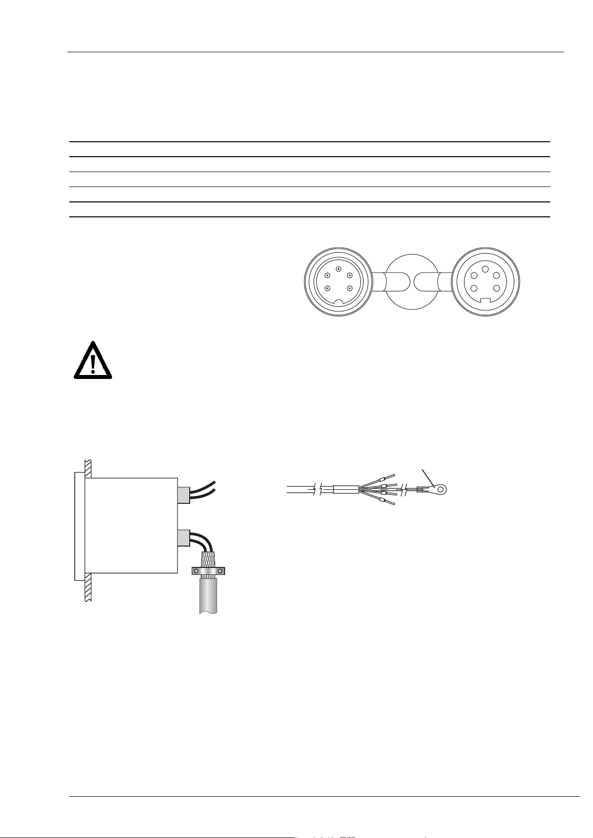
2. Terminal assignment
Spindle Position Display (SPA)
Pin Assignment Wire color DIN47100
Pin 1 Sensor supply +24 V yellow red
Pin 2 Sensor supply 0 V green black
Pin 3 -- -- --
Pin 4 Tx/Rx+, RS485 brown brown
Pin 5 Tx/Rx-, RS485 white orange
male M16 female M16
3
4
2
1
5
Connect power supply that is free from interference emission. The supply must not be used as
parallel supply of drives, shields, magnetic valves, etc.
Apply DC according to the terminal assignment
Power supply: 24 VDC ±10 %
IEC757
3
2
1
4
5
N 143
Shield
Use shielded cables only. Ground of the shield must be provided at the machine.
(two examples corresponding to the cable applied, see drawings).
Abschirmungsanschluss
4 www.baumer.com
Page 5

N 143
3. Interface
3.1. Interface data
Type: RS485
Baud rate: 19200
Parity: No
Data bits: 8
Stop bits: 1
Handshake: Nein
Redundancy check Yes (CRC)
Timeout reply*: 0,1...60 ms
BUS switching time** <0,1 ms ** The BUS switching time is the time required by the SPA to be ready again
3.2. Protocol
The spindle position display operates on ASCII protocol (clear text protocol). Depending on the command, the
protocol data package varies between 5 and 17 bytes.
Byte Hex-Code Significance Parameters
1 01H SOH = start of header ever 01h
2 XXh Adr = address 00...31dez + 20h Offset (address 00 = 20h)
3 XXh Cmd = command specific commands
4-n [XXh..XXh] [Data] = data 20h-7Fh
n+1 04h EOT = end of transmission ever 04h
n+2 XXh CRC = cyclic redundancy check 00h...FFh
3.3. Redundancy check (CRC byte)
For optimized error-free data communication the CRC byte is added after the footer (EOT, end of transmission)
to the string to be transmitted. Upon receiving a command the attached CRC byte is crosschecked with the
auto-calculated CRC byte.
Algorithm:
1) Reset CRC byte.
2) Rotate CRC byte by 1 bit to the left.
3) Link result to first data byte XOR.
4) Rotate result by 1 bit to the left.
5) Link result to the second data byte XOR.
:
x) Rotate result by 1 bit to the left.
y) Link result to the last data byte (ever 04H) XOR.
z) Add result as CRC after the footer indicator (04H) to the string to be transmitted.
Note:
Example:
String w/o CRC byte = 01h 20h 43h 04h
CRC-byte = 0Ah
0000 0000 RL 0000 0000 XOR 0000 0001 (01h) = 0000 0001
0000 0001 RL 0000 0010 XOR 0010 0000 (20h) = 0010 0010
0010 0010 RL 0100 0100 XOR 0100 0011 (43h) = 0000 0111
0000 0111 RL 0000 1110 XOR 0000 0100 (04h) =
Legend: RL = rotate left; XOR = antivalence link
1101 0000 RL 1010 0001 Important: Bit 7 is shifted in bit 0 during rotation
* To avoid bus collisions, a minimum timeout reply of 1 ms (default parame-
ter) is to be kept, i.e. the time elapsed between transmission of the last bit
in the request until start of transmission of the first bit in the SPA’s response.
The operator should see that due to the minimized timeout reply of 1 ms
the bus switching time after having transmitted the last bit must not exceed
1 ms.
Default parameters enable optional alteration by serial interface in increments of 0,1 ms within the range of 0,1...60 ms. Refer also to command „x“
(78h).
for transmission after having replied to the host.
0000 1010
= CRC
www.baumer.com 5
Page 6

N 143
3.4. Particularities in data communication
For reasons of compatibility, the entire multicon system operates on the same data length (see also table in
chapter „Command overview“). The data length does not relate to the number of digits in the display, i.e. command „R“ (read current value) implies transmission of 6 bytes whereas displayed are only 5. Digit 6 respectively
5 in negative values will ever come with a 0 (30h).
3.5. Broadcast commands
Some specific commands are so-called broadcast commands. Once the master transmits a command to address 99 it will be adopted by all multicon devices in the network. Each spindle position display will execute the
respective command but will not confirm to master.
3.6. Data saving
Specific parameters are saved in the EEPROM (1.000.000 writing cycles). Data saving is performed via interface upon every parameter transmission to the SPA. Important: We do not recommend cyclic transmission but
it would be wise after a parameter change only. Which parameters have been saved in the EEPROM can be
taken from the tables in chapter “Command explanations” or “Overview on commands”.
3.7. Transmission and reading of negative values
The negative sign (2DHex) ever comes in the 6th digit in the data field. Example: Negative target –1.50 implicates the transmission value –00150.
3.8. Transmission and reading of position values (decimal point)
In the transmission or reading of position values such as target (command „S“), offset (command „U“) or limit
positions (command „g“) the decimal point is generally omitted. The decimal point in the display corresponds to
the format in the data field of the interface command. Hence, the transmission format relates to the resolution
(see command „a“).
Example 1: Resolution = 1/100; target = 278.50;current value = 1,00 Display
SOH Adr Cmd Profile no=17
01h 20h 53h 31h 37h
Example 2: Resolution = 1/10; target = 278.5 current value = 1,0
SOH Adr Cmd Profile no=17
01h 20h 53h 31h 37h
30h 32h 37h 38h 35h 30h
30h 30h 32h 37h 38h 35h
target = 278,50
target = 278,5
EOT CRC
04h 29h
EOT CRC
04h 29h
2 7 8.5 0
1.0 0
2 7 8.5
1.0
6 www.baumer.com
Page 7

N 143
4. Command explanations
4.1. General
The following describes the individual interface commands which are broken down into the four groups below:
- operating commands [ commands required during operation ]
- parameter commands [ commands for SPA parameterization ]
- address commands [ commands to indicate or alter the device identifier (address)]
- specific commands [ commands for specific functionalities (device reset, version number readout]
The following abbreviations are applied:
SOH = Start of heading (header token)
EOT = End of transmission (footer token)
Adr = Device address, including offset 20h
Cmd = Command
SCmd = Sub command
Data = data transmitted or received
CRC = Cyclic redundancy check
4.2. Operating commands
Command
code
C (43h) 3 / 11 X - - - Check if current value = target
D (44h) 1 X X X - Start motor
F (46h) 4 X - - - Readout device status and error
R (52h) 6 X - - - Read current value
S (53h) 8 X X - X Read/write target
U (55h) 6 X X - - Offset
V (56h) 2 X X X X Read / write profile number
t (74h) 6 - X - - Transmit tool number
u (75h) 6 - X - - Transmit any optional number sequence
Z (5Ah) 6 X X X X Set preset
Data length
in bytes
read write Broad-
cast
Saved in
EEPROM
Significance
4.2.1. Check Position „C“ (43h)
This command provides the alignment status of target versus current value. If the current value is within the target tolerance window, the response will be „o“ (6Fh) for OK together with the current profile number. If the current value is outside the tolerances, „x“ (78H) followed by the current profile number will be replied. In case of
any error occurred at the SPA the response will be “e” together with the current profile number.
Example: (active profile number = 05)
Transmission
Response if current value within tolerance window: (Status = 6Fh = „o“)
Response
Response in case of current value outside tolerance window: (Status = 78h = „x“)
Response
Following status parameters are available:
Status Significance
o (6Fh) Current value = target
x (78h) Current value ≠ target
e (65h) SPA error
SOH Adr Cmd EOT CRC
01h 20h 43h 04h 0Ah
SOH Adr Cmd Stat. Profile no.=05EOT CRC
01h 20h 43h
SOH Adr Cmd Stat. Profile no.=05EOT CRC
01h 20h 43h
6Fh 30h 35h
78h 30h 35h
04h A5h
04h 1D
www.baumer.com 7
Page 8

N 143
Extended command Check Position „CX“
The extended command „Check Position CX “retrieves besides the alignment status of target versus current
value equally the contents of status and error register as well as the current value. The profile number is not
transmitted. For the relevant status parameters refer to the table above, the significance of the individual bits in
the status and error register is explained under command readout device status „F“.
Example:
Transmission
Response
SOH Adr Cmd
01h 20h 43h 58h 04h A8h
SOH Adr Cmd Stat. Status-Reg Error-Reg Curent value = -12,50 EOT CRC
01h 20h 43h
SCmd
EOT CRC
6Fh 80h 80h 80h 80h 2Dh 30h 31h 32h 35h 30h
04h B7h
8 www.baumer.com
Page 9

N 143
4.2.2. Start motor „D“ (44h)
This command retrieves the current SPA enable status and sets or withdraws the motor start signal.
The following modes are available:
Status Significance
0 (30h) abort start, motor stop
1 (31h) start SPAs of group 1
2 (32h) start SPAs of group 2
3 (33h) start SPAs of group 3
There are two options for motor start enable. In the first place, each SPA can be enabled individually, the order
is given by the host and may stretch over several groups. The enable command „D“ is transmitted to the respective device address together with the group number. The status LED is flashing fast which indicates active
motor control data transmission (see example 1 and 2).
Second, all SPAs clustered in a group can be enabled collectively using the broadcast command (address =
99). All SPAs of one group will indicate the enable status by their LEDs flashing at a frequency of 1 Hz. However, so far no motor control data have been transmitted. The operator will start control data transmission upon
pressing one of the buttons or by slightly turning the shaft of the respective SPA. Now the red LED is flashing
fast (example 3). The operation is aborted or disabled by pressing the button anew, which is indicated by the
LED flashing slowly. If the shaft does not experience any turn within 3 seconds after the enable signal, transmission of the control data will be automatically interrupted (LED flashing slowly.
Example 1: Readout current enable status (status = 0 = not enabled)
Transmission
Example 2: Start specific motor in group 1
Transmission
Example 3: Start all motors of group 2 by broadcast command (address = 99)
Transmission
Example 4: Abort all motor starts by broadcast command (address=99, stop commandl)
Transmission
: : :
SOH Adr Cmd EOT CRC
01h 20h 44h 04h 04h
Response
Response
Response Not confirmed
Response Not confirmed
SOH Adr Cmd Stat. EOT CRC
01h 20h 44h
SOH Adr Cmd Stat. EOT CRC
01h 20h 44h
SOH Adr Cmd Stat. EOT CRC
01h 20h 44h
SOH Adr Cmd Stat. EOT CRC
01h 83h 44h
SOH Adr Cmd Stat. EOT CRC
01h 83h 44h
30h
31h
31h
32h
30h
04h 64h
04h 66h
04h 66h
04h 7Dh
04h 79h
www.baumer.com 9
Page 10

N 143
4.2.3. Readout device status „F“ (46h)
This command retrieves the device statuses Stat1, Stat2 together with error flags Err1, Err2. In case of error,
the check command “C” will come with an “e” in reply.
Example:
Transmission
Response
Stat1: 1 0 0 0 0 0 0 X
┬ ─────┬───── ┬
│ │ └── Motor on standby for transmission
│ │ 0 = No motor start signal. SPA does not transmit any IR data
│ │ 1 = Motor start signal.
│ │ Interactive mode
│ │ SPA is enabled for alignment by power tool, however so far there
│ │ has not been any IR data transmission. LED is flashing slowly.
│ │ Motor start is enabled using the key.
│ │ Direct mode
│ │ SPA is enabled for alignment by power tool, IR data are being
│ │ transmitted. LED is flashing.
│ └───────── reserved
└──────────────── ever 1
Stat2: 1 0 0 0 0 0 0 X
┬ ─────┬───── ┬
│ │ └── 1 = SPA is transmitting motor commands. During motor start enable.
│ │ the bit will remain set. LED is flashing.
│ └───────── reserved
└──────────────── ever 1
Err1: 1 0 0 0 0 0 X X
┬ ──┬── ┬ ┬ ┬ ┬
│ │ │ │ │ └── 1 = Err 8 - target > MAX limit (motor does not start)
│ │ │ │ └──── 1 = Err 9 - target < MIN limit (motor does not start)
│
│ │ └──────── reserved
│ └──────────── reserved
└──────────────── ever 1
Err2: 1 0 0 X 0 0 X X
┬ ┬ ┬ ┬ ┬ ┬ ┬ ┬
│ │ │ │ │ │ │ └── 1 = Err 1 - MAX limit hurt
│ │ │ │ │ │ └──── 1 = Err 2 - MIN limit hurt
│ │ │ │ │ └────── reserved
│ │ │ │ └──────── reserved
│ │ │ └────────── 1 = Err 5 – target window not attained
│ │ └──────────── reserved
│ └──────────────
└──────────────── ever 1
SOH Adr Cmd EOT CRC
01h 20h 46h 04h 00h
SOH Adr Cmd Stat1 Stat2 Err1 Err2 EOT CRC
01h 20h 46h
80h 80h 80h 80h
04h 4Bh
(motor start signal via device address):
│ │ └────── reserved
reserved
(motor start by broadcast command):
10 www.baumer.com
Page 11

N 143
4.2.4. Read current value „R“ (52h)
This command reads the 6-digit current value (lower line of display). Data length is always 6 bytes. In case of a
negative value, the negative sign (2Dh) will be returned together with 5 data bytes. Positive values come in 6
data bytes without sign. Values inferior to 6 (5) digits will come with leading zeroes.
Example: current value = -32.50
Transmission
Response
SOH Adr Cmd EOT CRC
01h 20h 52h 04h 28h
SOH Adr Cmd Current value = –32,50 EOT CRC
01h 20h 52h
2Dh 30h 33h 32h 35h 30h
04h 54h
4.2.5. Read / write target (profile) „S“ (53h)
This command reads the presently active target, sets a specific target respectively reads out latter. Data comprise profile number (2 bytes) and target (6 bytes). Important: Negative targets come as a 5 digit number (see
example no. 3)
Example 1: read target of the current profile (current profile number = 12; target = 12.50)
Transmission
Response
Response upon having cleared all targets:
Response
Beispiel 2: Read target of a specific profile (profile number = 17; target = 12,50)
Transmission
Response
Example 3: Set target in a specific profile (profile number = 17; target = -12.50)
Transmission
Response
Note: Instead of command „S“ you may also use command „SP“. Functionality is fully identical to command
„S“. Due to the equal length of protocol it might be easier using SP in conjunction with command SD.
Example 4: As example 3, but using command „SP“
Transmission
Response
SOH Adr Cmd EOT CRC
01h 20h 53h 04h 2A
SOH Adr Cmd Profile =12 target = 12,50 EOT CRC
01h 20h 53h
SOH Adr Cmd Profile=FFh target = FFFFFFh EOT CRC
01h 20h 53h
SOH Adr Cmd Profile =17 EOT CRC
01h 20h 53h
SOH Adr Cmd Profile =17 target = 12,50 EOT CRC
01h 20h 53h
SOH Adr Cmd Profile =17 target = -12,50 EOT CRC
01h 20h 53h
SOH Adr Cmd Profile =17 target = -12,50 EOT CRC
01h 20h 53h
SOH Adr Cmd Sub Profile=17 target = -12,50 EOT CRC
01h 20h 53h
SOH Adr Cmd Sub Profile=17 target = -12,50 EOT CRC
01h 20h 53h
31h 32 30h 30h 31h 32h 35h 30h
3Fh 3F 3Fh 3Fh 3Fh 3Fh 3Fh 3Fh
31h 37h
31h 37h 30h 30h 31h 32h 35h 30h
31h 37h 2Dh 30h 31h 32h 35h 30h
31h 37h 2Dh 30h 31h 32h 35h 30h
50h
50h
04h 16h
31h 37h 2Dh 30h 31h 32h 35h 30h 04h 29h
31h 37h 2Dh 30h 31h 32h 35h 30h 04h 29h
04h 3E
04h 2Ah
04h BCh
04h FBh
04h FBh
www.baumer.com 11
Page 12

N 143
Direct positioning „SD“
This command is utilized for direct positioning operations. Only the current value without profile number will be
transmitted to the SPA.. Instead of transmitting the profile number, command “S” is followed by sub-command
“D” (dimension). Motor start requires the additional enable signal in command “D” .
Example: Set position value for direct positioning (without profile number):
Transmission
Response
SOH Adr Cmd Sub Position value = 278,25 EOT CRC
01h 20h 53h
SOH Adr Cmd Sub Position value = 278,25 EOT CRC
01h 20h 53h
44h 30h 32h 37h 38h 32h 35h
44h 30h 32h 37h 38h 32h 35h
04h 6Bh
04h 6Bh
Note: The position value will not be saved in the non-volatile memory. Consequently it is not retained after
power off but the previously active profile will be restored.
Target transmission with simultaneous motor enable signal
Some applications require automated self-positioning of a specific shaft when being provided with the new target without prior transmission of the enable signal in command „D“. The following commands serve this intention:
SPF transmits the profile value to the SPA. Motor start enabled for automated positioning
SDF transmits the position value to the SPA. Motor start enabled for automated positioning
Attaching the sub-command „F“ to the respective basic command will enable the addressed SPA. Groups remain unaffected, since only specific individual positioning operations are required. The operator must see that
any collisions are avoided.
Example: Set a specific target using command „SPF“ (profile no. = 17; target = -12.50)
Transmission
Response
SOH Adr Cmd Sub1 Sub2 Profile=17 target = -12,50 EOT CRC
01h 20h
SOH Adr Cmd Sub1 Sub2 Profile=17 target = -12,50 EOT CRC
01h 20h
53h 50h 46h
53h 50h 46h
31h 37h 2Dh 30h 31h 32h 35h 30h 04h A0h
31h 37h 2Dh 30h 31h 32h 35h 30h 04h A0h
12 www.baumer.com
Page 13

N 143
4.2.6. Read / set profile number „V“ (56h)
This command reads the number of the presently active profile respectively will change the profile.
Example 1: read active profile (active profile number = 38)
Send
Response
Response after reset upon deletion of all profiles:
Response
Example 2: transmit new profile (new profile number = 17)
Send
Response
Example 3: transmit new profile to all devices by broadcast command (adr = 99 (83h) ; new profile no. = 17)
Send
Response no confirmation
Command „C“ (43h) may be used to verify whether all SPAs have adopted the new profile.
SOH Adr Cmd EOT CRC
01h 20h 56h 04h 20h
SOH Adr Cmd Profile #=38 EOT CRC
01h 20h 56h
33h 38h
04h 28h
SOH Adr Cmd Profile #=FF EOT CRC
01h 20h 56h
3Fh 3Fh
04h 16h
SOH Adr Cmd Profile #=17 EOT CRC
01h 20h 56h
31h 37h
04h 3E
SOH Adr Cmd Profile #=17 EOT CRC
01h 20h 56h
31h 37h
04h 3E
SOH Adr Cmd Profile #=17 EOT CRC
01h 83h 56h
31h 37h
04h 04
4.2.7. Read/ set offset „U“ (55h)
This command reads or sets the offset which is added to the true current value. First the
functionality must be enabled in command bit parameter ‚a’ (61h).
Example 1: Read offset
Transmission
Example 2: Set offset
Tranmission
Response in both examples:
Response
SOH Adr Cmd EOT CRC
01h 20h 55h 04h 26h
SOH Adr Cmd data (offset = –20,00) EOT CRC
01h 20h 55h
2Dh 30h 32h 30h 30h 30h
04h C3h
SOH Adr Cmd data (offset = –20,00) EOT CRC
01h 20h 55h
2Dh 30h 32h 30h 30h 30h
04h C3h
www.baumer.com 13
Page 14

N 143
4.2.8. Set current value as preset „Z“ (5Ah)
Command “Z” sets the current value at any optional position. The required position value is transmitted to the
SPA which will calculate a so-called “preset offset” related to the true absolute encoder position. Any offset
which is set and transmitted by command “U” will be considered in the calculation, so that after execution of
command “Z” the current value is ever the preset.
The actual value in the display is composed as follows:
actual value
Current value
Current value
actual value in the display which is read out via interface
displ
internal absolute current value
abs
Preset offset offset calculated by command „Z“.
Offset Additional offset which may be set by command „U“. Firstly, the functionality must be en-
abled in command bit parameter ‚a’ (61h), otherwise the offset is 0.
Example 1: Read out the currently active preset
Transmission
Response
SOH Adr Cmd EOT CRC
01h 20h 5Ah 04h 38h
SOH Adr Cmd preset = 2,50 EOT CRC
01h 20h 5Ah
30h 30h 30h 32h 35h 30h
Example 2: Set current value as preset (preset = 17.25)
Transmission
Response
SOH Adr Cmd preset = 17,25 EOT CRC
01h 20h 5Ah
SOH Adr Cmd preset = 17,25 EOT CRC
01h 20h 5Ah
30h 30h 31h 37h 32h 35h
30h 30h 31h 37h 32h 35h
Example 3: Set current value as preset in all SPAs by broadcast command
Transmission
Response Not confirmed
SOH Adr Cmd preset = 17,25 EOT CRC
01h 83h 5Ah
30h 30h 31h 37h 32h 35h
= actual value
displz
+ preset offset + Offset
abs
04h 27h
04h 09h
04h 09h
04h AAh
4.2.9. Indicate tool number „t“ (74h)
The command writes a 6-digit tool number in the upper line of the display. The number is indicated without dot
respectively comma. Leading zeros as well as both direction arrows are suppressed. The lower line of the display still indicates the true current value.
The tool number will be displayed until any command except „t“, „u“ or „R“ is received via interface. The tool
number will be retained after power failure.
Example: (tool number = 654321)
Transmission
Response
SOH Adr Cmd Tool number = 654321 EOT CRC
01h 20h 74h
SOH Adr Cmd Tool number = 654321 EOT CRC
01h 20h 74h
36h 35h 34h 33h 32h 31h
36h 35h 34h 33h 32h 31h
04h 47h
04h 47h
14 www.baumer.com
Page 15

N 143
4.2.10. Indicate optional number sequence in the lower line of the display „u“ (75h)
The command writes a 6-digit number sequence in the lower display line. The sequence is indicated without dot
respectively comma. Leading zeros as well as both direction arrows are hidden. The upper line is still indicating
the current target or number sequence.
The number sequence will be displayed until any command except „t“, „u“ or „R“ is received via interface.
The number will be retained even after power failure.
Example: (number sequence = 123456)
Transmisison
Transmission
Note:
Combining the commands „t“ and „u“ enables a 12-digit number in the display. Neither number sequence nor
tool number will be saved.
SOH Adr Cmd Number sequence = 123456 EOT CRC
01h 20h 75h
SOH Adr Cmd Number sequence = 123456 EOT CRC
01h 20h 75h
31h 32h 33h 34h 35h 36h
31h 32h 33h 34h 35h 36h
04h BCh
04h BCh
www.baumer.com 15
Page 16

N 143
4.3. Parameter commands
Command
code
a (61h) 5 X X - X Read/write general parameters
b (62h) 8 X X - X Parameter: backlash compensation, tolerance
c (63h) 8 X X - X Parameter: Pitch scaling
g (67h) 12 X X - X Parameter: MIN, MAX limits
h (68h) 12 X X - X Parameter: Motor speed switching points
i (69h) 1 X X X X Parameter: mm / inch
j (69h) 3 X X X X Parameter: Timeout reply for bus error
k (6Bh) 9 X X - X Parameter: Motor system times
m (6Dh) 5 X X - X Read/write general parameters
x (78h) 5 X X - X Read/write specific parameters
4.3.1. Read/ write bit parameter standard „a“ (61h)
To make best use of the memory capacity, several parameters are compiled for packed transmission. Parameter encoding is as follows:
Data1: 1 0 X X 0 X 0 X
┬ ──┬── ─┬─ ─┬─
│ │ │ └─── Positioning direction 0/1 (UP/DOWN)
│ │ └─────── Counting direction 0/1 (UP/DOWN)
│ └──────────── Arrows 0/1/2/3 (UP/DOWN/UNI/OFF)
└──────────────── 1
Data2: 1 0 0 X 0 X 0 X
┬ ┬ ─┬─ ─┬─ ─┬─
│ │ │ │ └─── Rounding of current value 0/1 (OFF/ON)
│ │ │ └─────── Turn display 0/1 (OFF/ON)
│ │ └─────────── Offset 0/1 (OFF/ON)
│ └────────────── reserved
└──────────────── 1
Data3: 1 0 0 0 0 0 X X
┬ ────┬──── ─┬─
│ │ └─── Hide target 0/1/2 (ON/OFF/EVER)
│ └──────────
└──────────────── 1
Data4/5: 0 0 1 1 0 0 0 0
───┬───
└───── reserved
Note: Only the bits marked ‘X’ permit alteration. The permanent values ‚1’ and ‚0’ must remain unchanged since
otherwise control characters (characters < 20h) might be created which are not allowed in ASCII.
Exampe 1: Read out bit parameters (data 1 to data 3 = 80h; data 4 to data 5 = 30h)
Transmission
Response
Example 2: Write bit parameters (positioning direction = down; turn display = On)
Transmission
Response
Data length
in bytes
read write Broad-
cast
Saved in
EEPROM
reserved
SOH Adr Cmd EOT CRC
01h 20h 61h 04h 4E
SOH Adr Cmd Data1 Data2 Data3 Data4Data5 EOT CRC
01h 20h 61h
SOH Adr Cmd Data1 Data2 Data3 Data4Data5 EOT CRC
01h 20h 61h
SOH Adr Cmd Data1 Data2 Data3 Data4Data5 EOT CRC
01h 20h 61h
80h 80h 80h 30h 30h
81h 84h 80h 30h 30h
81h 84h 80h 30h 30h
04h F1
04h 91h
04h 91h
Significance
window
Bit parameter default
16 www.baumer.com
Page 17

N 143
Significance of parameter „a“
Positioning direction
This parameter defines the direction the target is headed for. For precise positioning, any tolerances at cogwheels, joints, shafts etc require backlash compensation which is performed by moving towards the target in socalled loops. A loop operation means first crossing the target position by a defined traveling distance for a second travel towards the target in the opposite direction. The parameter for the crossing distance is defined in
command “b”. Whether a loop operation is necessary will be indicated by the arrows in the display. A flashing arrow means backlash compensation required. When reaching the turning point the direction will change and the
arrow stops flashing. Targets which permit direct positioning operations are marked by a non-flashing arrow.
Once the target is attained within the stipulated tolerance window (see command “b”), the arrows will not disappear until the imperative backlash compensation has been performed.
00 = Up Direct positioning if target position > actual position; otherwise perform backlash compensation
01 = Down Direct positioning if target position < actual position; otherwise perform backlash compensation
Counting mode
This parameter assigns either „ascending“ or „descending” counted values in relation to the shaft’s direction of
rotation. Following parameters are available:
00 = Up Clockwise rotation, ascending counted values
01 = Down Clockwise rotation, descending counted values
Arrows
This parameter relates to the arrows in the display that indicate the operator the direction to choose (clockwise or
counter-clockwise, up/down) in the positioning operation. Following parameters are available:
00 = Up If actual value < target = arrow to the right; actual value > target = arrow to the left
01 = Down As „Up“, but inverted arrows direction
10 = Uni If actual value ≠ target arrows ever indicated
11 = Off Arrows ever hidden
Note: A loop operation (as backlash compensation) is only performed with settings Up and Down. Uni and Off always implicate a direct travel towards the target without backlash compensation.
Rounding the actual value
The actual value that is inside the tolerance window but still different from the target will be rounded to the target
value as soon as the shaft remains idle for approx. 3 seconds. The rounding operation is only visual, the true internal current value remains unchanged. For current value readout by serial interface (command “R”) the true, unrounded actual position value will be provided. The true current value will immediately reappear on the display
upon pressing a button. If the position is still within the tolerances, the rounding operation will be repeated after 3
seconds.
Note: In operating mode „Hide target = Ever“ the target is deactivated and the SPA will serve as pure current
value display. The rounding function is disabled. The following parameters are available:
0 = Off Rounding of current value disabled
1 = On Rounding of current value enabled
Turn display
This parameter permits turning the display in a 180° angle.
0 = Off Display readout with standard mounting, i.e. display above keypad
1 = On Display readout with inverted mounting, i.e. display below keypad
Offset
Command „U“ sets the offset which is added to both current value and current target. This parameter defines
whether the offset is enabled or disabled in the calculation.
0 = Off Offset disabled. Any offset previously transmitted is NOT added neither to actual value nor target.
1 = On Offset enabled. Offset is added to current value and actual target.
Hide target
This parameter defines when to indicate the target in the upper line of the display.
0 = On Indicate target if target ≠ current value.
1 = Off Ever indicate target, also if target = current value. Indicate arrows too if target ≠ current value.
2 = Ever Ever hide target and arrows.
www.baumer.com 17
Page 18

N 143
4.3.2. Read / write motor bit parameter „m“ (6Dh)
To make best use of the memory capacity, several parameters are compiled for packed transmission. Parameter encoding is as follows:
Data1: 1 0 0 0 0 X 0 X
┬ ──┬── ─┬─ ─┬─
│ │ │ └─── KEY key assignment 0/1 (UP/DOWN)
│ │ └─────── DIRECT Motor direction of rotation 0/1 (UP/DOWN)
│ └──────────── reserved
└──────────────── ever 1
Data2: 1 0 0 X 0 X X X
┬ ──┬── ┬ ──┬──
│ │ │ └──── reserved
│ │ └──────── reserved
│ └──────────── TYP axis type 0/1 (radial/axial)
└──────────────── ever 1
Data3: 1 0 0 X 0 X X X
┬ ┬ ─┬─ ┬ ──┬──
│ │ │ │ └──── GROUP 0 – 7 (group1/group2/…/group8)
│ │ │ └──────── reserved
│ │ └─────────── reserved
│ └────────────── reserved
└──────────────── ever 1
Data4/5: 0 0 1 1 X X X X 0 0 1 1 X X X X
───────┬─────── ───────┬─────── reserved Master axis address for
│ │ TraBa (transport bar)
│ └──────── ADR LSB (value range 30h to 39h)
└─────────────────────────── ADR MSB (value range 30h to 39h)
18 www.baumer.com
Page 19

N 143
Note: Only the bits marked ‘X’ permit alteration. The permanent values ‚1’ and ‚0’ must remain unchanged since
otherwise control characters (characters < 20h) might be created which are not allowed in ASCII protocols.
Example 1: Read bit parameter (Data 1 to Data 3 = 80h; Data 4 to Data 5 = 30h)
Transmission
Response
SOH Adr Cmd EOT CRC
01h 20h 6Dh 04h 56h
SOH Adr Cmd Data1 Data2 Data3 Data4Data5 EOT CRC
01h 20h 6Dh
80h 80h 80h 30h 30h
04h F2h
bit parameter default
Example 2: Write bit parameter (key assignment = down; motor direction = down)
Transmission
Response
SOH Adr Cmd Data1 Data2 Data3 Data4Data5 EOT CRC
01h 20h 6Dh
SOH Adr Cmd Data1 Data2 Data3 Data4Data5 EOT CRC
01h 20h 6Dh
81h 84h 80h 30h 30h
81h 84h 80h 30h 30h
04h 92h
04h 92h
Significance of parameter „m“
Key assignment
This parameter assigns a specific direction of rotation to a certain key. For mounting option “keypad below display” and the related default parameters applies the following:
0 = Up left/right key actuation = shaft rotation ccw/cw, counting mode UP/DOWN
1 = Down left/right key actuation = shaft rotation cw/ccw, counting mode UP/DOWN
Motor’s direction of rotation
The parameter “motor direction of rotation” enables inversion of the two output signals for motor ccw (pin B) and
motor cw (pin C) provided at the motor cable. The inversion is only effective with automated positioning. Manual
positioning operations by buttons remain unaffected.
0 = Up Standard direction of rotation
1 = Down Inverted direction of rotation
Shaft type
The shaft type parameter assigns the shaft type.
Some applications may call for different handling of radially and axially operated shafts what is already taken
into consideration when utilizing the Baumer IVO master. For example, only specific shafts are to be indicated in
DIM mode. When utilizing other masters (PLC or PC), this parameter may serve for general assignments.
0 = R Radial type
1 = A Axial type
Group
Parameter to classify groups. Individual SPAs can be assigned to one out of 8 individual groups to be started in
successive order (command „D“) to prevent collisions.
0 = Group 1
1 = Group 2
: :
7 = Group 8
To make best use of the memory capacity, several parameters are compiled for a packed transmission. Parameter encoding is as follows:
Note: Only the bits marked ‘X’ permit alteration. The permanent values ‚1’ and ‚0’ must remain unchanged since
otherwise control characters (characters < 20h) might be created which are not allowed in ASCII protocols.
Start signal for the respective group. Start command „D“ must include the related group number.
www.baumer.com 19
Page 20

N 143
4.3.3. Read / write backlash compensation and tolerance window „b“ (62h)
This command reads or writes the backlash compensation and tolerance window.
Example 1: Read parameter (backlash compensation = 0.15; tolerance window = 0.25)
Transmission
Response
SOH Adr Cmd EOT CRC
01h 20h 62h 04h 48h
SOH Adr Cmd backlash compensation=0.5 tolerance window=0.25 EOT CRC
01h 20h 62h
30h 30h 35h 30h 30h 30h 32h 35h
04h 0Bh
Example 2: Write parameter (backlash compensation = 1.30; tolerance window = 0.75)
Transmission
Response
SOH Adr Cmd backlash compensation =1.30 tolerance window =0.75 EOT CRC
01h 20h 62h
SOH Adr Cmd backlash compensation =1.30 tolerance window =0.75 EOT CRC
01h 20h 62h
30h 31h 33h 30h 30h 30h 37h 35h
30h 31h 33h 30h 30h 30h 37h 35h
04h 1Eh
04h 1Eh
4.3.4. Read / write spindle pitch (scaling) „c“ (63h)
This command reads or writes the scaling factor related to the spindle pitch within the range from
0.0000001...9.9999999. Transmission is without decimal point.
Resolution per turn is 2304 steps. A scaling factor of 1.000000 will increase respectively decrease the indicated
value by 23.04 mm.
How to calculate the scaling factor:
Resolution per turn: 23,04 mm (corresponding to length with scaling factor 1.0000000)
Spindle pitch: 4.00 mm
resolution per revolution 23.04
Example 1: Read out scaling factor (scaling factor = 1.000000)
Transmission
Example 2: Write scaling factor (scaling factor = 0.1736111)
Transmission
Spindle pitch 4.00
scaling = ───────────────── = ───── = 0,1736111
SOH Adr Cmd EOT CRC
01h 20h 63h 04h 4Ah
Response
Response
SOH Adr Cmd Scaling factor = 1,0000000 EOT CRC
01h 20h 63h
SOH Adr Cmd scaling factor= 0.1736111 EOT CRC
01h 20h 63h
SOH Adr Cmd Scaling factor = 0.1736111 EOT CRC
01h 20h 63h
31h 30h 30h 30h 30h 30h 30h 30h
30h 31h 37h 33h 36h 31h 31h 31h
30h 31h 37h 33h 36h 31h 31h 31h
04h 4B
04h 05h
04h 05h
20 www.baumer.com
Page 21

N 143
4.3.5. Read / write MIN and MAX limits „g“ (67h)
This command reads or writes the MIN and MAX limits within the range from -999.99 to 9999.99. Transmission
is without decimal point.
Example 1: Read limit positions (MIN = 15.00; MAX = 850.25)
Transmission
Response
SOH Adr Cmd EOT CRC
01h 20h 67h 04h 42h
SOH Adr Cmd MIN limit position = 0015.00 MAX limit position = 0850.25 EOT CRC
01h 20h 67h
30h 30h 31h 35h 30h 30h 30h 38h 35h 30h 32h 35h
04h 1Fh
Example 2: Write limit positions (MIN = -33.22; MAX = 1234.56)
Transmission
SOH Adr Cmd MIN limit position = -033.22 MAX limit position = 1234.56 EOT CRC
01h 20h 67h
2Dh 30h 33h 33h 32h 32h 31h 32h 33h 34h 35h 36h
04h 92h
Response SOH Adr Cmd MIN limit position = -033.22 MAX limit position = 1234.56 EOT CRC
01h 20h 67h
2Dh 30h 33h 33h 32h 32h 31h 32h 33h 34h 35h 36h
04h 92h
4.3.6. Read / write motor speed switching points „h“ (68h)
This command reads or writes the motor speed switching points. Prior to reaching the target the motor speed
can be slowed down to two optional speeds (slow and crawling) for positioning with pinpoint accuracy. The motor switchoff point can be equally set at an earlier stage prior to attaining the target. The following 2 parameters
are available:
The individual switching points are given in relation to the target.
Example 1: Read parameter (crawling speed = 0.70; point for switchoff = 0.00)
Transmission
Example 2: Write parameter (slow speed = 1.25; crawling speed = 0.50; point for switchoff = 0.01)
Transmission
Point of crawling speed: switching point to slow down from slow to crawling speed.
Point of switchoff: the SPA will stop the motor here.
SOH Adr Cmd EOT CRC
01h 20h 68h 04h 5Ch
Response
Response
SOH Adr Cmd reserved crawling speed =0.70 switchoff =0.00 EOT CRC
01h 20h 68h
30h 32h 30h 30h 30h 30h 37h 30h 30h 30h 30h 30h
SOH Adr Cmd reserved crawling speed =0,50 switchoff =0.01 EOT CRC
01h 20h 68h
30h 31h 32h 35h 30h 30h 35h 30h 30h 30h 30h 31h
SOH Adr Cmd reserved crawling speed =0,50 switchoff =0.01 EOT CRC
01h 20h 68h
30h 31h 32h 35h 30h 30h 35h 30h 30h 30h 30h 31h
04h 72h
04h EAh
04h EAh
www.baumer.com 21
Page 22

N 143
4.3.7. Read / write measuring unit „i“ (69h)
The command reads or writes the measuring unit in mm or inches.
Data = 0 (30h) = mm
Data = 1 (31h) = inch
Example 1: Read parameter (= mm)
Transmission
Response
Example 2: Change measuring unit into inches
Transmisison
Response
Example 3: Write measuring unit mm in all SPAs by broadcast command (address=99)
Transmission
Response not confirmed
Important:
Parameters are entered in mm and auto-converted into inches by the SPA upon displaying the position values.
SOH Adr Cmd EOT CRC
01h 20h 69h 04h 5E
SOH Adr Cmd Data EOT CRC
01h 20h 69h
30h
04h D0h
SOH Adr Cmd Data EOT CRC
01h 20h 69h
31h
04h D2
SOH Adr Cmd Data EOT CRC
01h 20h 69h
31h
04h D2
SOH Adr Cmd Data EOT CRC
01h 83h 69h
30h
04h CDh
4.3.8. R ead / write timeout at bus error RS485 „j“ (6Ah)
This command reads or writes the system time: Timeout reply at bus error. Value range is within 00.1 s to
99.9 s. Tolerance: ±7% at minimum time; < 1‰ at maximum time, approx. 1 % at 1 s.
Functionality: RS485 bus monitoring during motive shaft positioning operations. If there is no interface activity
within the programmed timeout the motor will stop (EMERGENCY OFF) in case of bus error or inactive master.
Motor restart requires transmission of the profile (command „S“ or „V“) including the start signal (command „D“).
Setting 0.00 s means function disabled.
Example 1: Read parameter (time= 2.5 s)
Transmission
Response
Example 2: Write parameter (time = 13.5 s)
Transmission
Response
SOH Adr Cmd EOT CRC
01h 20h 6Ah 04h 58h
SOH Adr Cmd Time =2.5 s EOT CRC
01h 20h 6Ah
30h 32h 35h
04h C5h
SOH Adr Cmd Loop =13.5 s EOT CRC
01h 20h 6Ah
31h 33h 35h
04h C9h
SOH Adr Cmd Loop =13.5 s EOT CRC
01h 20h 6Ah
31h 33h 35h
04h C9h
22 www.baumer.com
Page 23

4.3.9. Read / write motor system times „k“ (6Bh)
This command reads or writes the individual motor system times within the range of 00.1 s to 99.9 s.
Tolerance: ±7% at minimum time; < 1‰ at maximum time, approx. 1% at 1 s.
The following 3 parameters are available:
Example 1: Read parameter (loop = 1.0 s)
Transmission
Example 2: Write parameter (loop = 2.0 s)
Transmission
Loop: Waiting time at turning point during loop operation.
Trailing error: Timeout for motor signal, if shaft remains idle after the motor start signal
Clamping: Timeout reply between enabled/active clamping or braking action
prior to motor start signal / after motor stop signal.
SOH Adr Cmd EOT CRC
01h 20h 6Bh 04h 5Ah
Response
Response
SOH Adr Cmd Schleife=1,0 s reserved reserved EOT CRC
01h 20h 6Bh
SOH Adr Cmd loop=2.0 s reserved reserved EOT CRC
01h 20h 6Bh
SOH Adr Cmd loop=2.0 s reserved reserved EOT CRC
01h 20h 6Bh
30h 31h 30h 30h 30h 30h 30h 30h 30h
30h 32h 30h 30h 30h 30h 30h 30h 30h
30h 32h 30h 30h 30h 30h 30h 30h 30h
04h D9h
04h DAh
04h DAh
N 143
4.3.10. Read / write specific parameter „x“ (78h)
The specific parameter „x“ comprises several sub-parameters which permit alteration of originally permanent
parameters to adapt them to a new situation. The following sub-parameter is available:
D (44h) = delaytime for minimized timeout reply of the serial interface
Sub parameter: Delaytime „D“ (44h)
This parameter defines the minimum delay time (timeout) elapsed between the last bit received and the first bit
of the response transmitted. Delay time is in steps of 0.1 ms from 00.0 ... 60.0 ms. Default is 4.5 ms.
Example 1: Read current delay time
Transmission
Response
Example 2: Write new delay time
Transmission
Response
Please not that the true delaytime might be prolonged. It depends on the required processing time as well as on
internal software cycles. Tolerance is approx. 8 ms.
SOH Adr Cmd Sub EOT CRC
01h 20h 78h 44h 04h 7Ch
SOH Adr Cmd Sub Delaytime = 4.5 EOT CRC
01h 20h 78h 44h
SOH Adr Cmd Sub Delaytime = 15.0 EOT CRC
01h 20h 78h 44h
SOH Adr Cmd Sub Delaytime = 15.0 EOT CRC
01h 20h 78h 44h
30h 30h 34h 35h
30h 31h 35h 30h
30h 31h 35h 30h
04h BBh
04h BDh
04h BDh
www.baumer.com 23
Page 24

N 143
4.4. Address commands
Command
code
A (41h) 2 X X X X Allocate or indicate device address
B (42h) 2 - - - - SPA feedback in addressing mode
4.4.1. Device address allocation in the network „A“ (41h)
This command is generating an automated process to allocate the device address in successive order to each
networked SPA upon commissioning of the system. The first address to be allocated is broadcasted to the networked SPAs as follows:
Transmission
All SPAs show the address transmitted for allocation in their upper display lines. The lower lines indicate the
device-specific address.To have the new address adopted by the SPA, the shaft must experience a turn by half
at least (direction does not matter). The address has now been adopted and appears in the lower line of the display (as new device-specific address). Both addresses are now identical. As soon as the shaft is in idle position
again and after having elapsed 3 seconds, the SPA will reply command „B“ (42h) for confirmation to the master:
Transmission
to master
The master now transmits command „A“ with the next address to be allocated as previously described.
This way, each networked SPA is allocated its individual address in an automated process and in successive
order.
Important: Command „B“ transmitted by N 143 to master for confirmation will be repeated after 3 seconds provided the master has not previously transmitted command „A“.
Indicate address in the display „A“ (41h)
This command, less any parameters and applied as broadcast command (address=99) will make every networked SPA indicate its device-specific address in the lower display. The upper line is blind.
This command is a designated broadcast command.
Transmission
Response Not confirmed
The SPA will remain in this mode until being switched off and on again or until another command is received.
Extended address command „AX“ (41h, 58h)
This extended command is for addressing individual multicon devices in the bus network in a similar way as described above. All networked devices will receive the address to be allocated by broadcast command by the following procedure:
Transmission
Response Not confirmed
:
Equal to the standard command, all devices now indicate the address just received which is to be allocated in
the upper display. The address is adopted the same way. However, contrary to the above there is no
tion by command „B“ in reply. The master must verify whether the new address has been duly adopted, for example by command “R” (read current value). Command “ R” with the related address is transmitted to the position display. Once the addressed device has confirmed the successful allocation, the master will proceed with
next address. As soon as further commands are received, the respective position display will switch to standard
operation.
Data length
in bytes
SOH Adr Cmd identifier = 01 EOT CRC
01h 83h 41h
SOH Adr Cmd identifier = 01 EOT CRC
01h 21h 42h
SOH Adr Cmd EOT CRC
01h 83h 41h 04h 80h
SOH Adr Cmd Sub Adresse = 01 EOT CRC
01h 83h 41h 58h
read write Broad-
cast
30h 31h
30h 31h
04h B4h
04h 86h
30h 31h
Save in
EEPROM
04h 40h
Significance
confirma-
24 www.baumer.com
Page 25

N 143
4.5. Specific commands
command
code
K (4Bh) - - X X X Specific command: Clear profile (delete)
Q (51h) 1 - X X X Specific command: N 143 reset
X (58h) 2 / 4 / 8 X - - - Specific command: read device data
4.5.1. Clear profiles „K“ (4Bh)
This command will perform a collective deletion of all previously saved profiles.
Example 1: Clear profiles of a specific N 143
Transmission
Response
Example 2: Clear profiles in all positioning displays by broadcast command (Adr = 99)
Transmission
Response Not confirmed
Important: A profile reset operation will set all profile data to FFFFFFhex and the current profile number to
FFhex. In the display will appear 6 hyphens instead of the target.
data length
read write Broad-
in bytes
SOH Adr Cmd Data EOT CRC
01h 20h 4Bh
SOH Adr Data EOT CRC
01h 20h
SOH Adr Cmd Data EOT CRC
01h 83h 4Bh
6Fh
04h C6h
7Fh
04h 52h
04h DBh
7Fh
N 143 replies by standard response ‚o’ (6Fh) = OK
cast
saved in
EEPROM
functionality
4.5.2. N 143 reset „Q“ (51h)
This command will restore default in specific parameters, either individually or collectively.
Data = p (70h) = Reset digiset offset
Data = q (71h) = Restore default
Data = t (74h) = Restore 98 as device address.
Data = x (78h) = Multiturn counter is set to 4096 which corresponds to 0.
Data = ∆ (7Fh) = Execute all above functionalities .
Note: No profile reset. Please utilize command „R“ for a profile reset operation
Example 1: Restore default in a specific positioning display
Transmission
Response
Example 2: Restore default in all positioning displays by broadcast command (adr = 99)
Transmission
Response Not confirmed
SOH Adr Cmd Data EOT CRC
01h 20h 51h
SOH Adr Data EOT CRC
01h 20h
SOH Adr Cmd Data EOT CRC
01h 83h 51h
6Fh
04h AEh
7Fh
04h 52h
04h B3
7Fh
N 143 replies by standard response ‚o’ (6Fh) = OK
www.baumer.com 25
Page 26

N 143
4.5.3. Read version or serial number „X“ (58h)
This command reads out version number, device type or serial number. The following sub-commands are available:
Data = V (56h) = read out version number
Data = T (54h) = read out device type
Data = S (53h) = read out serial number
Example 1: Read out version number
Transmission
Response
Example 2: Read out device type (Device type = 82h = N 143; software no. = 01)
Transmission
Response
Structure of the encoded device type transmitted:
1 0 0 1 0 1 0 1 1 0 0 0 0 0 0 1 = 95 81 hex
┬ ──────┬────── ┬ ───────┬─────
│ │ │ └─────── software no. 01h = software 01
│ │ └──────────────── ever 1
│ └────────────────────────── device type 15h = N 155
└────────────────────────────────── ever 1
Example 3: Read out serial number
Transmission
Response
Structure of the encoded serial number transmitted:
The Low-Nibble (lower 4 bits of a byte) of the 8 data bytes received equal a 4-byte value encoding the serial
number.
The serial number is composed of production date and time. Since the seconds come encoded as well and per
second only one number will be allocated, the serial number is unique and unambiguous.
Example: serial number for production date and time 01.06.2005 16:58:36 = 15 83 0E A4 hex
X X X X X X X X X X X X X X X X X X X X X X X X X X X X X X X X Bit position
J J J J J J M M M M T T T T T h h h h h m m m m m m s s s s s s content
0 0 0 1 0 1 0 1 1 0 0 0 0 0 1 1 0 0 0 0 1 1 1 0 1 0 1 0 0 1 0 0 example = 15 83 0E A4 hex
─────┬───── ────┬──── ────┬──── ─────┬───── ──────┬────── ─────┬─────
│ │ │ │ │ └─────── seconds 10
│ │ │ │ └──────────────────── minutes 11
│ │ │ └───────────────────────────────── hours 1
│ │ └──────────────────────────────────────────── day 0
│ └────────────────────────────────────────────────────── month
└───────────────────────────────────────────────────────────────── year 00
│
01.06.05 16:58:36 <──────┘
SOH Adr Cmd Data EOT CRC
01h 20h 58h
56h
04h D8h
SOH Adr Cmd Data Versionsnummer = 2.00 EOT CRC
01h 20h 58h 56h
20h 32h 30h 30h
04h FAh
SOH Adr Cmd Data EOT CRC
01h 20h 58h
54h
04h DCh
SOH Adr Cmd Data Typ EOT CRC
01h 20h 58h 54h
82h 81h
04h 6Eh
SOH Adr Cmd Data EOT CRC
01h 20h 58h
53h
04h D2h
SOH Adr Cmd Data Encoded serial number = 07090EA4 EOT CRC
01h 20h 58h 53h
30h 37h 30h 39h 30h 3Eh 3Ah 34h
04h 20h
0100 = 24h = 36d
1010 = 3Ah = 58d
0000 = 10h = 16d
0001 = 01h = 01d
0110 = 06h = 06d
0101 = 05h = 05d
26 www.baumer.com
Page 27

N 143
4.6. CRC error
Upon identification of a CRC error in a command transmitted, the positioning display will reply by the following
response:
Response
SOH Adr Error EOT CRC
01h 20h 65h 04h 46h Error = „e“ (65h) = CRC error
4.7. Format error
Upon identification of a format error in a command transmitted (incorrect length of protocol or unvalid command
(Cmd), the positioning display will reply by the following response:
Response
SOH Adr Error EOT CRC
01h 20h 66h 04h 40h Error = „f“ (66h) = Format error
5. Command overview
In the following table is a list of all available commands (Cmd) in alphabetical order, along with the corresponding read and write access.
Command
code
a (61h) 5 X X - X Read/write general parameters
b (62h) 8 X X - X Parameters: Backlash, tolerance window
c (63h) 8 X X - X Parameter: Pitch scaling
g (67h) 12 X X - X Parameter: MIN and MAX limits
h (68h) 12 X X - X Parameter: Motor speed switching points
i (69h) 1 X X X X Parameter: mm / inch
k (6Bh) 9 X X - X Parameter: Motor system times
m (6Dh) 5 X X - X Read/write general parameters
t (74h) 6 - X - - Transmit tool number
u (75h) 6 - X - - Transmit available number sequence
x (78h) 5 X X - X Read/write specific parameters
A (41h) 2 X X X X Allocate or indicate device address
B (42h) 2 - - - - SPA response in addressing mode
C (43h) 3 / 11 X - - - Verify if current value = target
D (44h) 1 X X X - Motor start signal
F (46h) 4 X - - - Read out device status and device error
K (4Bh) - - X X X Specific command: Clear (delete) profile
Q (51h) 1 - X X X Specific command: N 143 reset
R (52h) 6 X - - - Read current value
S (53h) 8 X X - X Read/write target value
U (55h) 6 X X - - Offset
V (56h) 2 X X X X Read/write profile number
X (58h) 2 / 4 / 8 X - - - Specific command: Read device data
Z (5Ah) 6 X X X X Set preset
Data length
in bytes
read write Broad-
cast
Saved in
EEPROM
Functionality
www.baumer.com 27
Page 28

N 143
6. Error messages
Error messages are visualized by a flashing upper display, alternating between error code and the presently active value (normally the target).
MAX limit of the SPA hurt by manual positioning operation.
Troubleshooting: Get SPA back to permitted positioning range.
Troubleshooting: Get SPA back to permitted positioning range.
Troubleshooting: Extend tolerance window. Switch to crawling speed at an earlier point.
Troubleshooting: Transmit new permissible position value.
Troublehsooting: Transmit new permissible position value.
MIN limit of the SPA hurt by manual positioning operation.
SPA does not attain the target window.
The target transmitted is outside the MAX limit.
Note: Consider loop operations.
The target transmitted is outside the MIN limit.
Note: Consider loop operations.
28 www.baumer.com
Page 29

7. Technical data
7.1. Technical product specifications
Electrical data
Supply voltage 24 VDC ±10 %
Current consumption <40 mA
Display 7-segment LCD, 2 lines, backlit
Measuring principle Absolute multiturn measuring system
Measuring range -999,99...+9999,99 mm
-99.999...+999.999 inch
Resolution/ steps per turn 2304
Number of turns/resolution 4096 / 12 Bit
Spindle pitch ≤23 mm
Interface RS485 (ASCII protocol)
Data memory Parameter buffer: EEPROM
Current value buffer: >10 years by integrated 3 V Lithium cell
Programmable parameters Display position horizontal/vertical mounting
Measuring unit mm/inch
Counting direction
Pitch
Backlash
Positioning direction
Direction arrows
Tolerance window
Rounding functionality
Motive positioning Two buttons with optional microstep operation for position alignments
by power tool via infrared interface
Standard DIN EN 61010-1 Protection class II
Overvoltage category II
Soiling degree 2
Emitted interference DIN EN 61000-6-3
Interference immunity DIN EN 61000-6-2
Certificates UL/cUL
Mechanical data
Hollow shaft ø25 mm
Rotational speed ≤600 rpm (short-term)
Protection DIN EN 60529 IP 65 (housing), IP 40 (connector)
Ambient temperature -10...+50 °C
Storage temperature -20...+70 °C
Relative humidity 80 % non-condensing
Torque support Torque pin provided at housing
E-connection Cable output (30 cm) with 5-pin mating connector M16
User interface / keypad Two keys on keypad
Housing With hollow shaft
Dimensions W x H x L 56 x 100 x 62.5 mm
Mounting Hollow shaft attachment
Weight approx. 200 g
Material Polycarbonate black, UL 94V-0
N 143
www.baumer.com 29
Page 30

7.2. Dimensions
IR-Diode
Status-LED
25 H7
(20 H7)
58.5
Fixierstift
für Bohrung
Ø
10 mm
100
40 ±0.2
37
Ø
Hohlwelle Ø25 mm
7
8
20°
M5
37
Ø
Hohlwelle
Ø
20 mm
N 143
M5
37
Ø
10
1
62.5 21.5
16
56
8. Part number
N 143.103AA01 Spindle position display with hollow shaft ø20 mm
N 143.103AB01 Spindle position display with hollow shaft ø25 mm
6
4
8.5
M16-Buchse
M16-Stecker
30 www.baumer.com
 Loading...