

Page 1

Operating instructions
Interface Description
N 142 Spindle Positioning Display (SPA)
Software 01 Version 3.20 and up
Contents Page
1. General information 2
1.1. Safety precautions 2
1.2. SPA description and explanation 3
2. Terminal assignment 4
3. Interface 6
3.1. Interface data 6
3.2. Protocol 6
3.3. Redundancy check (CRC byte) 6
3.4. Broadcast commands 7
3.5. Data saving 7
3.6. Transmitting and reading negative values 7
3.7. Transmitting and reading position values (decimal point) 7
4. Command explanations 8
4.1. General information 8
4.2. Operating parameters 8
4.3. Parameter commands 15
4.4. Identifier (address) commands 25
4.5. Specific commands 27
4.6. CRC error 29
4.7. Format error 29
5. Overview on commands 29
6. Error warnings 30
7. Technical data 31
7.1. Dimensions 32
8. Part number 32
Baumer IVO GmbH & Co. KG 05.11
Dauchinger Strasse 58-62 • DE-78056 Villingen-Schwenningen Subject to modification
Phone +49 (0)7720 942-0 • Fax +49 (0)7720 942-900 in technic and design.
www.baumer.com • info.de@baumerivo.com
• 171.02.292/10
Page 2
N 142
1. General information
1.1. Safety precautions
General remarks
The equipment is designed and assembled according to the prevailing regulations of technology. The
equipment left the manufacturer in perfect working order and in line with all safety-relevant conditions. To
maintain this status of the equipment, it is imperative to stick to the following when installing and using the
device:
- use only according to the intended purpose,
- observation of any precautions regarding safety and hazards,
- observe the present manual and especially the relevant safety precautions!
Make sure that the operating manual and especially the chapter describing the safety precautions is read and
well understood by the staff in charge. Supplementary to the operating instructions, ad other generally or legally
relevant regulations regarding accident prevention and environmental care are to be considered and observed.
This manual is a supplement to already existing documentation (product information, mounting instructions,
catalogues).
Intended purpose of the equipment
Intended purpose of the equipment is industrial process monitoring and control in metal, wood, plastic, paper,
glass and textile etc. industry.
It is imperative that the equipment is applied only
- in properly installed condition and
- in line with the relevant technical data !
Any operation outside the technical specifications/parameters is improper use and in conjunction
with the equipment/processes/machines to be monitored/controlled might lead to
- fatal injuries
- serious damage to health,
- damage to property or corporate equipment or
- damage to the device!
Any overvoltage the device might be exposed to at its connecting terminals has to be limited to the values
stipulated in overvoltage category II (see technical data).
The device must not be operated
- in hazardous areas where is danger of explosion,
- as medical equipment or in medical areas,
- or in any applications expressly named in EN 61010!
If the device is utilized for control/monitoring of machines or processes where as the result of a
failure/malfunction or incorrect operation of the device might occur
- any threats to life,
- risks of damage to health or
- any risk of damage to property or environment
The corresponding appropriate safety precautions must be taken!
Do not open the housing of the device or proceed any modifications! Tampering with the device can affect
operating safety and result in danger!
Do not proceed any repairs but return defective devices to the manufacturer!
Installation/Commissioning
In case of any extraordinary incidents (including in the operating behaviour) that impair safety switch off the
device immediately.
Installation must be carried out by suitably trained experts only. After proper mounting and installation the
device is ready for operation
Maintenance/repairs
Always disconnect the power supply of all appliances involved. Maintenance and repair work must only be
carried out by suitably trained experts.
If troubleshooting is unsuccessful, do not continue using the device but contact the manufacturer.
.
www.baumer.com 2
Page 3

N 142
1.2. SPA description and explanation
Mounting the spindle position display (SPA) is by docking the hollow shaft to the end of the spindle shaft. The
hollow shaft is fixed by hexagon screw to the spindle shaft and secured by power grip.
This way, the SPA is mounted over-hung and secured against torsion at rear of the housing by the attached
spreader pin. The spindle position display features an absolute multiturn sensing system allowing to capture the
position after several turns of the spindle even in powerless status. The position data will be retained even in
case of power failure (min. 10 years).
The current position value is displayed in the two-line backlit LCD display (2x 6 digits, numeric). Simultaneously,
in the same display the target transmitted by the control (master) is indicated. Two arrows show the editing
engineer the direction the spindle is to be turned in order to align the current value with the target. As soon as
the current value equals the target and is within the allowable tolerance, the target will disappear.
The SPAs are networked by cable cut to length providing male and mating connector. Power supply for all
connected SPAs is by the same cable.
Upper line of the display “target“
Arrows indicating the direction of rotation for target/current value alignment
Bottom line of the display „current value“
N 142 enables motor connection using the 12-core cable. Two softkeys on the
keypad serve for manual motor trigger. Automatic motor trigger by master is also
possible by separate motor supply.
www.baumer.com 3
Page 4

2. Terminal assignment
Spindle position display
Pin Assignment Core colour DIN47100
Pin 1 Sensor supply +24 V yellow red
Pin 2 Sensor supply 0 V green black
Pin 3 -- -- --
Pin 4 Tx/Rx+, RS485 brown brown
Pin 5 Tx/Rx-, RS485 white orange
Male connector M16 Female connector M16
3
4
2
1
5
Terminal assignment of motor connection to N142 SPA
SPA N142 is connected to motor using the 12-pin female connector.
Pin Assignment Significance Core colour
Pin A -- -- --
Pin B IN 1 motor ccw yellow
Pin C IN 2 motor cw blue
Pin D IN 4* speed green
Pin E +24 V -- red
Pin F external softkey 1 softkey position orange
Pin G external softkey 2 softkey position violet
Pin H -- n.c. --
Pin J -- n.c. --
Pin K OUT 3 error signal white
Pin L IN 3* speed brown
Pin M GND GND black
IN 3* IN 4* Rotation speed rpm. Dunker
1 0 slow 200
0 1 average -1 1 fast 3600
IEC757
B
A
L
C
D
M
E
F
3
2
1
4
5
K
J
H
G
N 142
www.baumer.com 4
Page 5
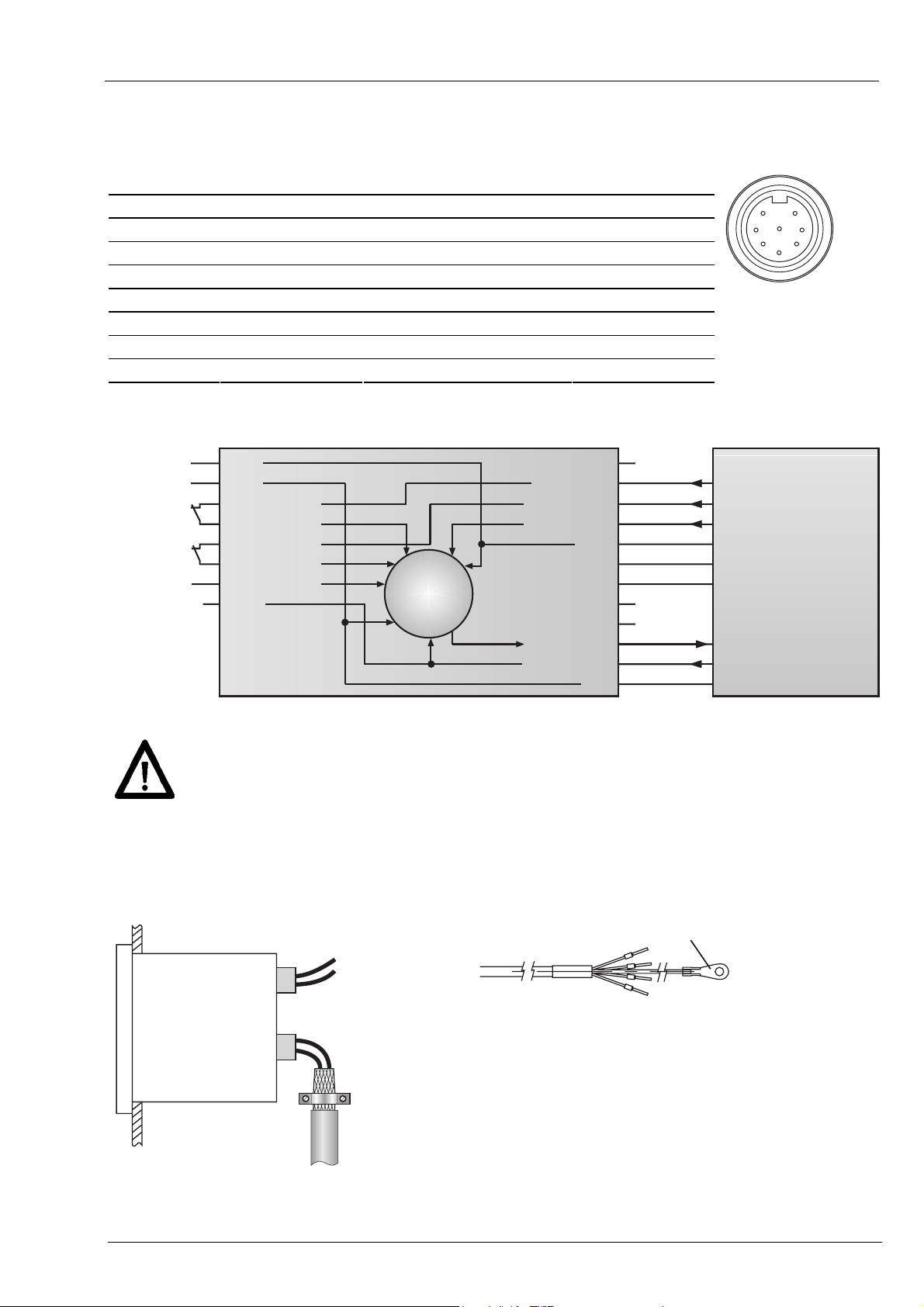
Connecting the motor supply
Motor supply is by the 8-pin connector provided at the motor.
Pin Assignment Significance Core colour
Pin 1 Ue + 24 V motor supply red
Pin 2 GND 0 V reference ground for Ue blue
6
1
Pin 3 OUT ccw start ccw run white
Pin 4 IN ccw start ccw run brown
Pin 5 OUT clockwise start cw run green
Pin 6 IN clockwise start cw run yellow
Pin 7 Enable logic +24 V grey
Pin 8 n.c. n.c. pink
Switching diagram
Versorgung
Freigabe
Linkslauf
Freigabe
Rechtslauf
Enable
Klemmung
1
24 V
2
0 V
3
IN 1 Ausgang
4
IN 1 Eingang
5
IN 2 Ausgang
6
IN 2 Eingang
7
(Logik 24 V)
8
Motor – BG650
M
OUT 1
IN 1 (links)
IN 2 (rechts)
IN 4 (speed)
AI- (0...10 V)
AI+ (0...10 V)
OUT 3 (fault)
IN 3 (speed)
24 V
n.c.
n.c.
0 V
A
B
C
D
E
F
G
H
J
K
L
M
Error
Linkslauf
Rechtslauf
Drehzahl
intern nicht beschaltet
Taste 1 extern
Taste 2 extern
nicht belegt
nicht belegt
Motorstörung
Drehzahl
GND
Connect power supply that is free from interference emission. The supply must not be used as
parallel supply of drives, shields, magnetic valves, etc.
Apply DC according to the terminal assignment
Power supply: 24 VDC ±10 %
7
8
3
5
4
2
SPA – N 142
N 142
Shield
Use shielded cables only. Ground of the shield must be provided at the machine.
(two examples corresponding to the cable applied, see drawings).
Abschirmungsanschluss
www.baumer.com 5
Page 6

N 142
3. Interface
3.1. Interface data
Type: RS485
Baudrate: 19200
Parity: no
Data bits: 8
Stop bits: 1
Handshake: no
Redundancy check: yes (CRC)
Timeout reply*: 0,1...60 ms
BUS switching time**: <0,1 ms
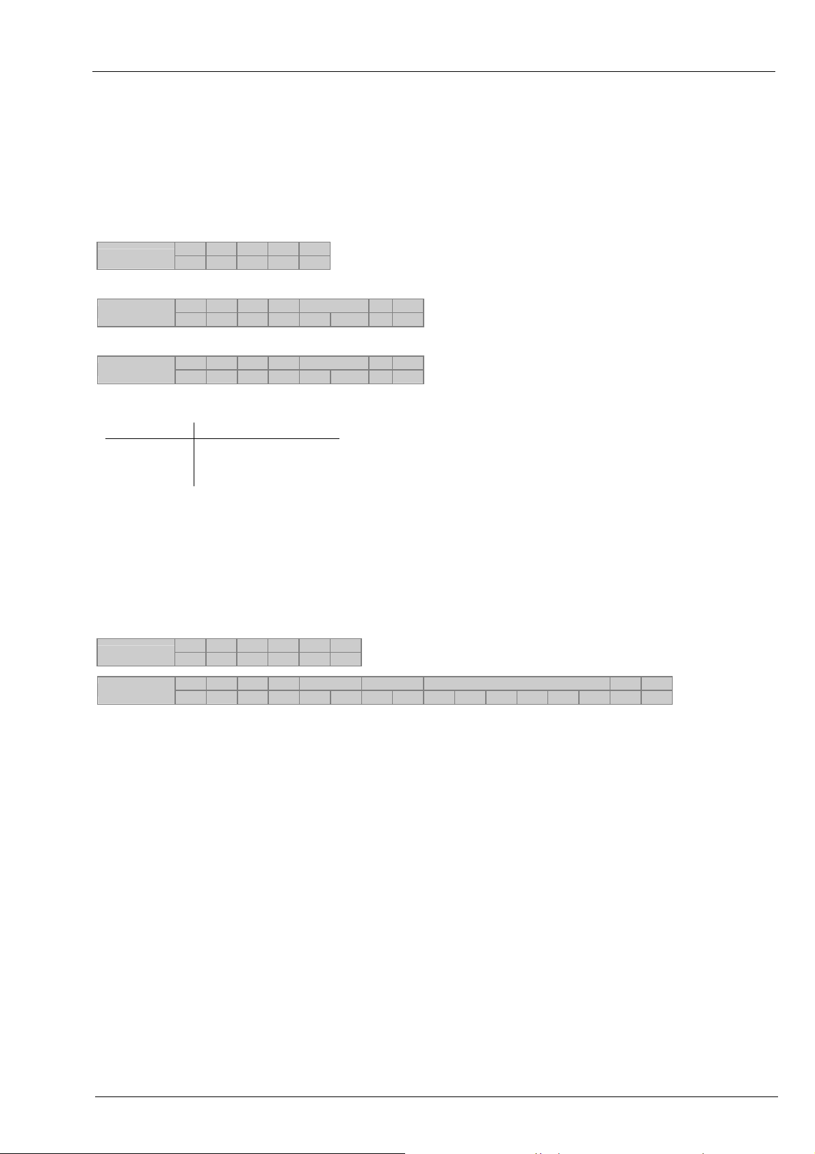
3.2. Protocol
The spindle position display operates with ASCII protocol (clear text protocol). Depending on the command, the
protocol data package varies between 5 and 17 bytes.
Byte Hex-Code Significance Parameters
1 01H SOH = start of heading permanent on 01h
2 XXh Adr = address 00...31dez + 20h Offset (address 00 = 20h)
3 XXh Cmd = command specific commands
4-n [XXh..XXh] [Data] = data 20h-7Fh
n+1 04h EOT = end of transmission permanent 04h
n+2 XXh CRC = cyclic redundancy check 00h...FFh
3.3. Redundancy check (CRC byte)
For optimized error-free data transmission the CRC byte is added after the footer token (EOT, end of
transmission) to the string to be transferred. Upon receiving a command the CRC byte transmitted is
crosschecked with the auto-calculated CRC byte.
Algorithm:
1) Reset CRC byte.
2) Rotate CRC byte by 1 bit to the left.
3) Link result to first data byte XOR.
4) Rotate result by 1 bit to the left.
5) Link result to the second data byte XOR.
:
x) Rotate result by 1 bit to the left.
y) Link result to the last data byte (ever 04H) XOR.
z) Add result as CRC after the footer token (04H) to the transmitted string.
Note:
Example:
String less CRC = 01h 20h 43h 04h
CRC-Byte = 0Ah
0000 0000 RL 0000 0000 XOR 0000 0001 (01h) = 0000 0001
0000 0001 RL 0000 0010 XOR 0010 0000 (20h) = 0010 0010
0010 0010 RL 0100 0100 XOR 0100 0011 (43h) = 0000 0111
0000 0111 RL 0000 1110 XOR 0000 0100 (04h) =
Legend: RL = rotate left; XOR = antivalence link
1101 0000 RL 1010 0001 Important: Bit 7 is shifted in bit 0 during rotation
* To avoid bus collisions a minimum timeout reply of 1 ms (default parameter)
is to be kept, i.e. the time elapsed between transmitting the last bit of the
query until start transmitting the 1st bit of the SPA response.
The operator should see that due to the minimized timeout reply of 1 ms
the bus switching time after having transmitted the last bit must not exceed
1 ms.
The default parameter of 1 ms can optionally be altered by serial interface
in steps of 0,1 ms within the range of 0,1 ... 60 ms. Refer to command „x“
(78h).
** The BUS switching time is the time the SPA requires to be ready again for
reception after having replied to the host
0000 1010
= CRC
www.baumer.com 6
Page 7

N 142
3.4. Broadcast commands
Some specific commands are designated so-called broadcast commands. As soon as the master broadcasts a
command to identifier 99, the command is addressed to all N 142 in the network. Every individual spindle
position display will accomplish the respective command but will not respond any confirmation to master.
3.5. Data saving
Specific parameters are saved in EEPROM (1.000.000 writing cycles). Data saving is via interface upon every
parameter transmission to the SPA.
Important:
These parameters should not be transmitted to SPA cyclic but only if necessary, for example in case of any
parameter alteration. The relevant parameters that are saved in EEPROM are listed in the charts in chapter
“Command explanations” or “Overview on commands”.
3.6. Transmitting and reading negative values
The minus sign (2DHex) is always transmitted by digit 6 of the data field.
Example: Taking for granted a negative target of –1,5 and a programmed resolution of 1/10, the transmitted
value is –00015.
3.7. Transmitting and reading position values (decimal point)
Position values as for example target (command „S“), offset (command „U“) or end positions (command “g”) are
generally transmitted and read without decimal point. The visualization on the display corresponds to the format
in the data field of the interface command.
Example 1: target = 278.50; actual value = 1.00 Display
SOH Adr Cmd Profil-Nr=17
01h 20h 53h 31h 37h
Sollwert = 278,50
30h 32h 37h 38h 35h 30h
EOT CRC
04h 29h
2 7 8.5 0
1.0 0
www.baumer.com 7
Page 8

4. Command explanations
4.1. General information
The following is describing the individual interface commands broken down into the four groups below:
- operating commands [ commands required during operation ]
- parameter commands [ commands for SPA parameterization ]
- identifier commands [ commands to indicate or alter the device identifier (address)]
- specific commands [ commands for specific functions as device reset or version number readout]
The following abbreviations are applied:
SOH = Start of heading (header token)
EOT = End of transmission (footer token)
Adr = Device address, including offset 20h
Cmd = Command
SCmd = Sub command
Data = data transmitted or received
CRC = Cyclic redundancy check
4.2. Operating parameters
Command Data amount
in bytes
C (43h) 3 / 11 X - - - Check if current value = target
D (44h) 1 X X X - Start motor
F (46h) 4 X - - - Readout device status and error
R (52h) 6 X - - - Read current value
S (53h) 8 X X - X Read/write target
U (55h) 6 X X - - Offset
V (56h) 2 X X X X Read/write profile number
Z (5Ah) 6 X X X X Set preset
t (74h) 6 - X - - Transmit tool number
u (75h) 6 - X - - Transmit any optional number sequence
read write Broad-
cast
Save in
EEPROM
Significance
N 142
www.baumer.com 8
Page 9
N 142
4.2.1. Check Position, command „C“ (43h)
This command provides the alignment status of target versus current value. If the current value is within the
target tolerance window, the response will be „o“ (6Fh) for OK together with the current profile number. If the
current value is outside the tolerances, „x“ (78H) followed by the current profile number will be replied. In case
of any error occurred at the SPA the response will be “e” together with the current profile number.
Example: (active profile number = 05)
Transmission
Response if current value within tolerance window: (Status = 6Fh = „o“)
Response
Response in case of current value outside the tolerance window: (Status = 78h = „x“)
Response
SOH Adr Cmd EOT CRC
01h 20h 43h 04h 0Ah
SOH Adr Cmd Stat. Profile no.=05EOT CRC
01h 20h 43h
SOH Adr Cmd Stat. Profile no.=05EOT CRC
01h 20h 43h
6Fh 30h 35h
78h 30h 35h
04h A5h
04h 1D
Following status parameters are possible:
Status Significance
o (6Fh) Current value = target
x (78h) Current value ≠ target
e (65h) SPA error
Extended command Check Position „CX“
The extended command „Check Position CX “provides besides the alignment status target versus current value
also the contents of the status and error register as well as the current value. The profile number is not
transmitted.
For the relevant status parameters refer to the table above, the significance of the individual bits in the status
and error register is explained under command readout device status „F“.
Example:
Transmission
Response
SOH Adr Cmd
01h 20h 43h 58h 04h A8h
SOH Adr Cmd Stat. Status-Reg Error-Reg Curent value = -12,50 EOT CRC
01h 20h 43h
SCmd
EOT CRC
6Fh 80h 80h 80h 80h 2Dh 30h 31h 32h 35h 30h
04h B7h
4.2.2. Read parameter start motor, command „D“ (44h)
This command is utilized to read the current SPA status parameter respectively to program or delete the motor
start parameter.
The following modes are available:
Status Significance
0 (30h) abort start, motor stop
1 (31h) start SPAs of group 1
2 (32h) start SPAs of group 2
3 (33h) start SPAs of group 3
Start is also released by broadcast command (identifier = 99) to all SPAs at the same time. Refer to example 3.
: : :
www.baumer.com 9
Page 10

N 142
Example 1: Readout current status (Status = 0 = not released)
Transmission
Response
Example 2: Start a specific motor
Transmission
Response
SOH Adr Cmd EOT CRC
01h 20h 44h 04h 04h
SOH Adr Cmd Stat. EOT CRC
01h 20h 44h
SOH Adr Cmd Stat. EOT CRC
01h 20h 44h
SOH Adr Cmd Stat. EOT CRC
01h 20h 44h
30h
31h
31h
04h 64h
04h 66h
04h 66h
Example 3: Start all motors by broadcast command (identifier = 99)
Transmission
Response Not confirmed
SOH Adr Cmd Stat. EOT CRC
01h 83h 44h
31h
04h 7Bh
Motor holding torque off / on, command „DB“ (44h, 42h)
Prior to utilizing the “DB” command to disable / enable the holding torque it must be activated first in command
„m“ since otherwise command „DB“ remains ineffective.
Holding torque always enable means that only motive shaft positioning operations are possible - either by aid of
the two keys provided or by a corresponding command via interface. The holding torque is automatically
disabled as soon as the motor is getting a start command and will later automatically be re-enabled. Manual
positioning operations by hand cranks etc require disabling the holding torque first by command “DB”.
Following modes are available:
Status Function
0 (30h) holding torque disable
1 (31h) holding torque enable
Example 1: Read out current status (status = 0 : without holding torque)
transmitted
response
SOH Adr Cmd
01h 20h 44h 42h 04h 80h
SOH Adr Cmd
01h 20h 44h 42h
SCmd
EOT CRC
SCmd
Stat. EOT CRC
30h
04h 6Dh
Example 2: Disable holding torque (status = 0 : unblock holding torque)
transmitted
response
SOH Adr Cmd
01h 20h 44h 42h
SOH Adr Cmd
01h 20h 44h 42h
SCmd
Stat. EOT CRC
30h
SCmd
Stat. EOT CRC
30h
04h 6Dh
04h 6Dh
Example 3: Disable holding torque for all motors by broadcast-command (ID=99)
transmitted
response not confirmed
SOH Adr Cmd
01h 83h 44h 42h
SCmd
Stat. EOT CRC
30h
04h 57h
Note: If the holding torque is enabled (command „m“), clamping will always be activated upon power on, reason
why holding torque OFF by command „DB0“ remains only effective whilst device is under power supply.
www.baumer.com 10
Page 11

N 142
4.2.3. Readout device status, command „F“ (46h)
This command provides the device statii Stat1, Stat2 together with error flags Err1, Err2. In case of error check
command “C” will come with an “e” in reply.
Example:
Transmission
Response
Stat1: 1 0 0 0 0 0 0 0
┬ ──────┬──────
│ └──────── reserved
└──────────────── ever 1
Stat2: 1 0 0 0 0 0 X X
┬ ────┬──── ┬ ┬
│ │ │ └── 1 = Motor is running (Moving Bit). The bit is set with running motor
│ │ └──── 1 = Manual SPA abort. Bit is set upon actuating one of SPA keys during
│ └────────── reserved
└──────────────── ever 1
Err1: 1 0 0 0 0 0 0 0
┬ ──┬── ┬ ┬ ┬
│ │ │ │ │ └── 1 = Err 8 - target > limit MAX (no motor start)
│ │ │
│ │ │ └────── reserved
│ │ └──────── reserved
│ └──────────── reserved
└──────────────── ever 1
Err2: 1 0 0 0 0 X X X
┬ ┬ ┬ ┬ ┬ ┬ ┬ ┬
│ │ │ │ │ │ │ └── 1 = Err 1 – hurt limit MAX
│ │ │ │ │ │ └──── 1 = Err 2 – hurt limit MIN
│ │ │ │ │ └────── 1 = Err 3 – no shaft rotation
│ │ │ │ └──────── 1 = Err 4 – motor failure (overload current)
│ │ │ └────────── 1 = Err 5 – target window not achieved
│ │ └──────────── 1 = Err 6 – trailing error
│ └──────────────
└──────────────── ever 1
SOH Adr Cmd EOT CRC
01h 20h 46h 04h 00h
SOH Adr Cmd Stat1 Stat2 Err1 Err2 EOT CRC
01h 20h 46h
80h 80h 80h 80h
04h 4Bh
and during loop interval.
With active clipped connections the bit will remain set as
│ long as the connections are open.
an automated positioning operation.
│ └──── 1 = Err 9 - target < limit MIN (no motor start)
reserved
www.baumer.com 11
Page 12

N 142
4.2.4. Read current value, command „R“ (52h)
This command is for readout the 6-digit current value (bottom display line). The amount of data is always 6
bytes. In case of a negative value, the “-“ sign (2Dh) together with 5 data bytes is replied. Positive values are
represented by 6 data bytes without sign. Values of less than 6 (5) digits will come with preceding zeroes.
Example: Current value = -32,50
Transmission
Response
SOH Adr Cmd EOT CRC
01h 20h 52h 04h 28h
SOH Adr Cmd Current value = –32,50 EOT CRC
01h 20h 52h
2Dh 30h 33h 32h 35h 30h
04h 54h
4.2.5. Read / write target (profile), command „S“ (53h)
This command is for readout the presently active target or for programming respectively reading a specific
target. The data are composed of profile number (2 bytes) and target (6 bytes). Important: Negative targets
come by 5 digits only (see example no. 3).
Example 1: Read target of the active profile (current profile number = 12; target = 12,50)
Transmission
Response
Response upon deletion of all targets:
Response
Example 2: Read target of a specific profile (profile number = 17; target = 12,50)
Transmission
Response
Example 3: Write target of a specific profile (profile number = 17; target = -12,50)
Transmission
SOH Adr Cmd EOT CRC
01h 20h 53h 04h 2A
SOH Adr Cmd Profile no.=12 Target = 12,50 EOT CRC
01h 20h 53h
SOH Adr Cmd Profile=FFh Target = FFFFFFh EOT CRC
01h 20h 53h
SOH Adr Cmd Profile no=17 EOT CRC
01h 20h 53h
SOH Adr Cmd Profile no=17 Target = 12,50 EOT CRC
01h 20h 53h
SOH Adr Cmd Profile no.=17 Target = -12,50 EOT CRC
01h 20h 53h
31h 32 30h 30h 31h 32h 35h 30h
3Fh 3F 3Fh 3Fh 3Fh 3Fh 3Fh 3Fh
31h 37h
31h 37h 30h 30h 31h 32h 35h 30h
31h 37h 2Dh 30h 31h 32h 35h 30h
04h 16h
04h 3E
04h 2Ah
04h BCh
04h FBh
Response
SOH Adr Cmd Profile =17 Target = -12,50 EOT CRC
01h 20h 53h
31h 37h 2Dh 30h 31h 32h 35h 30h
04h FBh
Direct positioning „SD“
This command may be utilized for direct positioning operations. Only the target less any profile number is
transmitted to SPA. The profile number after the command “S” is replaced by sub command “D” (0 =
dimension). Motor start requires transmission of the additional motor start command “D”.
Example 4: Write position value for direct positioning (less profile)
Transmission
Response
SOH Adr Cmd Sub Position value = 278,25 EOT CRC
01h 20h 53h
SOH Adr Cmd Sub Position value = 278,25 EOT CRC
01h 20h 53h
44h 30h 32h 37h 38h 32h 35h
44h 30h 32h 37h 38h 32h 35h
04h 6Bh
04h 6Bh
Note: The position value is saved in the non-volatile memory and will be retained in case of power failure. In this
case the previously selected profile will be utilized again.
www.baumer.com 12
Page 13

N 142
4.2.6. Read / write profile number, command „V“ (56h)
This command is for readout the number of the presently active profile respectively for profile alteration.
Example 1: Read active profile (active profile number = 38)
Transmission
SOH Adr Cmd EOT CRC
01h 20h 56h 04h 20h
SOH Adr Cmd Profile no=38 EOT CRC
Response
Response after reset upon deletion of all profiles:
01h 20h 56h
33h 38h
04h 28h
SOH Adr Cmd Profile no=FF EOT CRC
Response
01h 20h 56h
3Fh 3Fh
04h 16h
Example 2: Transmit new profile (new profile number = 17)
SOH Adr Cmd Profile no=17 EOT CRC
Transmission
01h 20h 56h
31h 37h
04h 3E
SOH Adr Cmd Profile no=17 EOT CRC
Response
01h 20h 56h
31h 37h
04h 3E
Example 3: Transmit new profile by broadcast to all SPAs (identifier = 99 (83h); new profile number = 17)
SOH Adr Cmd Profile no=17 EOT CRC
Transmission
01h 83h 56h
31h 37h
04h 04
Response Not confirmed
To check whether the new profile has been accepted by SPAs utilize check command „C“ (43h).
4.2.7. Read / write offset, command „U“ (55h)
This command is to read or write the offset that is added to the true current value. First however the function
must be enabled in command bit parameter ‚a’ (61h).
Example 1: Read offset
Transmission
Example 2: Write offset
Transmission
Response in both examples:
Response
SOH Adr Cmd EOT CRC
01h 20h 55h 04h 26h
SOH Adr Cmd Data (offset = –20,00) EOT CRC
01h 20h 55h
2Dh 30h 32h 30h 30h 30h
04h C3h
SOH Adr Cmd Data (offset = –20,00) EOT CRC
01h 20h 55h
2Dh 30h 32h 30h 30h 30h
04h C3h
www.baumer.com 13
Page 14

N 142
4.2.8. Align current value with preset, command „Z“ (5Ah)
The Z command is for setting the current value to any optional position. The required position value is
transmitted to the SPA. The SPA will calculate a so-called “preset offset” -value relating to the true absolute
sensor position. When calculating the preset offset any programmed offset transmitted by command “U” will be
considered, so that after having accomplished the “Z” command the current value always equals the preset.
Note: For technical reasons there is no preset offset scaling what might result in misalignments due to rounding
operations. In this case, the current value displayed is by 1 LSB inferior or superior to the programmed preset
value.
The current value displayed is composed as follows:
Current value
Current value
Current value
current value display and readout by interface
Anz
internal absolute current value.
Abs
= current value
Anz
+ Preset offset + Offset
Abs
Preset offset Offset generated by command „Z“.
Offset Additional offset defined by command „U“. This function however must be enabled in
command bit parameter ‚a’ (61h), otherwise offset = 0.
Example 1: Readout the currently active preset
Transmission
Response
SOH Adr Cmd EOT CRC
01h 20h 5Ah 04h 38h
SOH Adr Cmd Preset = 2,50 EOT CRC
01h 20h 5Ah
30h 30h 30h 32h 35h 30h
04h 27h
Example 2: Align actual value with preset (preset = 17,25)
Transmission
Response
SOH Adr Cmd Preset = 17,25 EOT CRC
01h 20h 5Ah
SOH Adr Cmd Preset = 17,25 EOT CRC
01h 20h 5Ah
30h 30h 31h 37h 32h 35h
30h 30h 31h 37h 32h 35h
04h 09h
04h 09h
Example 3: Align actual value to preset by broadcast at all SPA´s
Transmission
Response Not confirmed
SOH Adr Cmd Preset = 17,25 EOT CRC
01h 83h 5Ah
30h 30h 31h 37h 32h 35h
04h AAh
4.2.9. Readout any optional number sequence in the upper line of display,
command „t“ (74h)
This command is for indicating a 6-digit number sequence in the upper line of the display. The sequence is
indicated without dot respectively comma. Preceding zeroes as well as both direction arrows are suppressed.
The bottom display line still indicates the current value.
The number is displayed until any command except „t“, „u“ or „R“ is received by interface. The number will be
retained after power failure.
Example: (number sequence = 654321)
Transmission
Response
SOH Adr Cmd Number sequence = 654321 EOT CRC
01h 20h 74h
SOH Adr Cmd Number sequence = 654321 EOT CRC
01h 20h 74h
36h 35h 34h 33h 32h 31h
36h 35h 34h 33h 32h 31h
04h 47h
04h 47h
www.baumer.com 14
Page 15

N 142
4.2.10. Readout any optional number sequence in the bottom line of display,
command „u“ (75h)
The command is for indicating a 6-digit number in the bottom line. The number is displayed without dot
respectively comma. Preceding zeroes as well as both direction arrows are suppressed. The upper line still
indicates the current target or number sequence.
The number sequence is displayed until any optional command except „t“, „u“ or „R“ is received by the interface.
The number will be retained after power failure.
Example: (number sequence = 123456)
Transmission
Response
SOH Adr Cmd Number sequence = 123456 EOT CRC
01h 20h 75h
SOH Adr Cmd Number sequence = 123456 EOT CRC
01h 20h 75h
31h 32h 33h 34h 35h 36h
31h 32h 33h 34h 35h 36h
04h BCh
04h BCh
Important:
Command “t” in conjunction with command “u” enables displaying a 12-digit number.
Both numbers are not saved in EEPROM.
4.3. Parameter commands
Command Amount of data
in Bytes
a (61h) 5 X X - X Read / write general parameters
b (62h) 8 X X - X Parameter: Tolerance compensation, window
c (63h) 8 X X - X Parameter: Scaling spindle pitch
g (67h) 12 X X - X Parameter: Limits MIN, MAX
h (68h) 12 X X - X Parameter: Switching points for motor speed.
i (69h) 1 X X X X Parameter: mm / inch
j (69h) 3 X X X X Parameter: Timeout for bus error
k (6Bh) 9 X X - X Parameter: Motor system cycles
l (6Ch) 5 X X - X Parameter: Jog
m (6Dh) 5 X X - X Read / write general parameters
x (78h) 5 X X - X Read / write specific parameters
read write Broad-
cast
Saved in
EEPROM
Significance
www.baumer.com 15
Page 16

N 142
4.3.1. Read / write bit parameter standard, command „a“ (61h)
To exploit maximum memory capacity, several parameters are put together and transferred as “data pack”
under the following parameter codes:
Data1: 1 0 X X 0 X 0 X
┬ ──┬── ─┬─ ─┬─
│ │ │ └─── positioning direction 0/1 (UP/DOWN)
│ │ └─────── counting direction 0/1 (UP/DOWN)
│ └──────────── arrows 0/1/2/3 (UP/DOWN/UNI/OFF)
└──────────────── 1
Data2: 1 0 0 X 0 X 0 X
┬ ┬ ─┬─ ─┬─ ─┬─
│ │ │ │ └─── rounding the current value 0/1 (OFF/ON)
│ │ │ └─────── turn display 0/1 (OFF/ON)
│ │ └─────────── Offset 0/1/2 (OFF/SER/S+K)
│ └────────────── reserved
└──────────────── 1
Data3: 1 0 0 X X 0 X X
┬ ┬ ──┬── ┬ ─┬─
│ │ │
│ │ │ └────── reserved
│ │ └────────── external inputs 0/1/2/3 (Key/Slow/Middle/Fast)
│ └────────────── reserved
└──────────────── 1
Data4/5: 0 0 1 1 0 0 0 0 0 0 1 1 0 0 0 0
───────┬─────── ───────┬───────
│ └──────── reserved
└─────────────────────────── reserved
Important: Only the bits marked ‘X’ may be altered. The permanent parameters „1“ and „0“ must not be altered
since this might create a control token ( tokens < 20h) what is not permitted in ASCII protocol.
Example 1: Read bit parameter (Data 1 to Data 3 = 80h; Data 4 to Data 5 = 30h)
Transmission
Response
Example 2: Write bit parameter (positioning direction = down; turn display = On)
Transmission
Response
SOH Adr Cmd EOT CRC
01h 20h 61h 04h 4E
SOH Adr Cmd Data1 Data2 Data3Data4 Data5 EOT CRC
01h 20h 61h
SOH Adr Cmd Data1 Data2 Data3 Data4 Data5 EOT CRC
01h 20h 61h
SOH Adr Cmd Data1 Data2 Data3 Data4 Data5 EOT CRC
01h 20h 61h
│ └─── hide target 0/1/2 (ON/OFF/EVER)
Bit parameter default
80h 80h 80h 30h 30h
04h F1
81h 84h 80h 30h 30h
81h 84h 80h 30h 30h
04h 91h
04h 91h
www.baumer.com 16
Page 17

N 142
Significance of parameter „a“
Positioning direction
This parameter defines in which direction the target is headed for. Compensating tolerances, for example at
cogwheels, joints, shafts etc during a precise positioning operation requires a tolerance compensation. The
tolerance compensation is proceeded by heading for the target position always from the same direction by socalled loops. Loops mean that the target position is first crossed by a defined distance and then headed for again
from the opposite direction. The parameter for the crossing distance is programmed by command “b”. Whether a
loop is required or not can be seen from the direction arrows on the display. A flashing arrow means a tolerance
compensation is required. Upon reaching the turning point the direction changes and the arrow stops flashing. A
target enabling direct positioning is marked by a non-flashing arrow. Upon reaching the target within the
programmed tolerances (see command “b”) the arrows will not disappear until the required tolerance
compensation was completed.
00 = Up Direct positioning if target position > current position; otherwise proceed tolerance compensation
01 = Down Direct positioning if target position < current position; otherwise proceed tolerance compensation
Counting mode
This parameter assigns either „ascending“ or „descending” counted values in relation to the shaft’s direction of
rotation. Following parameters are available:
00 = Up Clockwise rotation, ascending counted values
01 = Down Clockwise rotation, descending counted values
Arrows
This parameter relates to the arrows in the display that show the operator the direction (to the right or to the left)
of the new positioning operation. Following parameters are available:
00 = Up If current value < target = arrow to the right; current value > target = arrow to the left
01 = Down As „Up“, but inverted direction of the arrows
10 = Uni If current value ≠ target indicate both arrows
11 = Off Arrows ever hidden
Note: A loop operation (for backlash compensation) is only performed with settings Up and Down. Uni and Off
always implicate a direct movement to the target without backlash compensation.
Rounding the current value
This means that the current value being within the tolerances but still differing from the target is rounded up or
down to the target value as soon as the shaft remains idle for approx. 3 seconds. The rounding operation is only
visual, the true internal current value remains unchanged. For current value readout by serial interface (command
“R”) the true, not rounded current position value is provided. The true current value will immediately reappear on
the display upon actuating a key. If the position is still within the tolerance window the rounding operation will be
repeated after 3 seconds.
Note: In operating mode „Hide target = Ever“ the target is deactivated and the SPA serves as a pure current
value display with disabled rounding function. The following parameters are available:
0 = Off Rounding the current value disabled
1 = On Rounding the current value enabled
Turn display
This parameter turns the display by 180°.
0 = Off Display readout with standard mounting, i.e. display above keypad
1 = On Display readout with inverted mounting, i.e. display below keypad
www.baumer.com 17
Page 18

N 142
Offset
Command „U“ is for programming the offset that is added to the current value and current target. This parameter
defines whether the offset is considered in the calculation.
Parameter 2 means optional manual offset alteration directly at the device itself. Press both softkeys at the same
time and proceed offset alteration by turning the shaft. Press the softkeys anew to quit. The bottom line shows
the unchanged current value again. The value alteration emerging from the shaft turn has been assigned to the
offset.
0 = Off Offset disabled. The previous offset transmitted - if any - is neither added to current value nor
target.
1 = SER Offset enabled. Offset is added to the actual current value.
Offset alteration by serial interface
2 = S+K Offset enabled. The offset is added to the respective current value.
Offset alteration either by serial interface or manually at the device.
Hide target
This parameter defines when to indicate the target in the upper line of the display.
0 = On Ever indicate target if target ≠ current value.
1 = Off Ever indicate target, even if target = current value. Indicate also arrows if target ≠ current value.
2 = Ever Ever hide both target and arrows.
External inputs
This parameter defines the external input operation.
0 = Key Function identical to N142 keypad
1 = Slow Motor in slow motion
2 = Middle Average motor speed (only if 3 optional speeds available, otherwise high speed)
3 = Fast Motor in fast motion
4.3.2. Read / write motor bit parameter „m“ (6Dh)
To exploit the maximum memory capacity, several parameters are put together and transmitted as „data pack“
under the following parameter codes:
Data1: 1 0 X X 0 X 0 X
┬ ──┬── ─┬─ ─┬─
│ │ │ └─── KEY Key assignment 0/1 (UP/DOWN)
│ │ └─────── CORRECT Sense of motor rotation 0/1 (UP/DOWN)
│ └──────────── JOG Activation MicroStep 0/1/2/3 (UP/DOWN/EVER/ONLY)
└──────────────── 1
Data2: 1 0 X X 0 0 0 0
┬ ──┬── ┬ ──┬──
│ │ │ └──── reserved
│ │ └──────── reserved
│ └──────────── TYP shaft type 0/1/2/3 (radialDim/axialDim/radial/axial)
└──────────────── 1
Data3: 1 0 0 X 0 X X X
┬ ┬ ┬ ┬ ┬ ──┬──
│ │ │ │
│ │ │ │ └──────── reserved
│ │ │ └────────── coupled shafts 0/1 (OFF/ON)
│ │ └────-─────── holding torque 0/1 (OFF/ON)
│ └────────────── reserved
└──────────────── 1
Data4/5: 0 0 1 1 X X X X 0 0 1 1 X X X X
───────┬─────── ───────┬─────── Leading shaft identifier for assigned shafts
│ └──────── ADR LSB (value range 30h to 39h)
└─────────────────────────── ADR MSB (value range 30h to 39h)
│ └──── GROUP 0 – 7 (group 1/group 2/…/group 8)
www.baumer.com 18
Page 19

N 142
Important: Only bits marked ‘X’ may be altered. The permanent values „1“ and „0“ must not be altered since
thereby a control token ( tokens < 20h) might be created what is not permitted in ASCII.
Example 1: Read bit parameter (Data 1 to Data 3 = 80h; Data 4 to Data 5 = 30h)
Transmission
Response
SOH Adr Cmd EOT CRC
01h 20h 6Dh 04h 56h
SOH Adr Cmd Data1 Data2 Data3Data4 Data5 EOT CRC
01h 20h 6Dh
80h 80h 80h 30h 30h
04h F2h
Bit parameter default
Example 2: Write bit parameter (key assignment = down; direction of motor rotation = down)
Transmission
Response
SOH Adr Cmd Data1 Data2 Data3 Data4 Data5 EOT CRC
01h 20h 6Dh
SOH Adr Cmd Data1 Data2 Data3 Data4 Data5 EOT CRC
01h 20h 6Dh
81h 84h 80h 30h 30h
81h 84h 80h 30h 30h
04h 92h
04h 92h
Significance of parameter „m“
Key assignment
This parameter assigns a specified direction of rotation to a certain key. For the mounting option “keypad below
display” and the remaining default parameters applies the following:
0 = Up left/right key actuated = shaft rotation ccw/cw, counting mode UP/DOWN
1 = Down left/right key actuated = shaft rotation cw/ccw, counting mode UP/DOWN
Motor direction of rotation
The parameter “motor direction of rotation” enables inversion of the two output signals for motor ccw (pin B) and
motor cw (pin C) provided at the motor cable.
0 = Up standard direction of rotation
1 = Down inverted direction of rotation
Jog
The jog function makes the motor run by a defined number of steps upon a short stroke on a key. The holding
time does not matter as long as it is not less than 400 ms. A holding time of > 400 ms results in permanent motor
run. Inferior holding times are accomplished as Jog. The number of steps is defined under parameter command
„l“, default parameter is 1.
Note: The respective step is always accomplished completely and cannot be stopped or restarted by actuating
any key during the motor positioning operation. However a stop by interface (command “D”) is possible. With
running motor the moving bit is set to 1 (refer also command “F”).
Setting the step width to 0 will disable the Jog function, both by keypad and by external inputs.
00 = Up Jog only enabled with counting mode UP
01 = Down Jog only enabled with counting mode DOWN
10 = Ever Jog enabled with both counting modes UP/DOWN
11 = Only Jog only enabled. Continuous movements actuated by keypad are disabled.
Shaft type
The shaft type parameter assigns the shaft type.
Some applications may call for different treatment of radially and axially operated shafts what is already taken into
consideration when utilizing the Baumer IVO master. For example, only certain shafts shall be displayed in DIM
mode. Other controls (for example PLC or PC) may utilize this parameter for general assignments.
00 = radialDim This is a radial shaft displayed in DIM mode.
01 = axialDim This is an axial shaft displayed in DIM mode.
10 = radial This is a radial shaft not displayed in DIM mode.
11 = axial This is an axial shaft not displayed in DIM mode.
www.baumer.com 19
Page 20

N 142
Groups
Parameter for division in groups. Individual SPAs can be bundled to 8 different groups to be started in successive
order group by group (command „D“) in order to prevent collisions.
0 = Group 1
Start command „D“ must comprise the designated group number to start the respective group.
1 = Group 2
: :
7 = Group 8
Assigned shafts
This parameter assigns two or more shafts to a leading shaft and is applied when utilizing the Baumer IVO
Master. For detailed description please refer to the Baumer IVO master user manual, chapter specific functions.
Other controls (for example PLC or PC) may utilize this parameter for general assignments.
0 = Off Assignment disabled
1 = On Assignment enabled. This SPA is assigned to a leading shaft. The leading shaft’s identifier is
specified in data 4/5 of command “m” in the leading shaft address.
Holding torque
This parameter is utilized to enable respectively disable the motor holding torque. Both directional signals “motor
ccw” and “motor cw” are activated by the spindle position display (SPA). Thus, the motor is hold at its actual
position. Refer also to command „DB“ for temporarily disabling the holding torque.
0 = Off holding torque disabled
1 = On holding torque enabled
4.3.3. Read /write parameters spindle tolerance and tolerance window,
command „b“ (62h)
This command is to read or write the parameters tolerance compensation and tolerance window.
Example 1: Read parameter (tolerance compensation = 0,15; tolerance window = 0,25)
Transmission
Response
Example 2: Write parameter (tolerance compensation = 1,30; tolerance window = 5,00)
Transmission
Response
SOH Adr Cmd EOT CRC
01h 20h 62h 04h 48h
SOH Adr Cmd compensation=0,15 Toelrance window=0,25 EOT CRC
01h 20h 62h
SOH Adr Cmd compensation.=1,30 Tolerance window=5,00 EOT CRC
01h 20h 62h
SOH Adr Cmd compensation.=1,30 Tolerance window=5,00 EOT CRC
01h 20h 62h
30h 30h 31h 35h 30h 30h 32h 35h
30h 31h 33h 30h 30h 35h 30h 30h
30h 31h 33h 30h 30h 35h 30h 30h
04h AAh
04h 20h
04h 20h
www.baumer.com 20
Page 21

N 142
4.3.4. Read / write parameter spindle pitch (scaling), command „c“ (63h)
This command is utilized to read or write the scaling factor relating to the spindle pitch within the range from
0,0000001...9,9999999. The decimal point is not transmitted.
Resolution per turn is 2304 steps. A scaling factor of 1.000000 will increase respectively decrease the indicated
value by 23.04 mm.
How to calculate the scaling factor:
Resolution per turn: 23.04 mm (corresponding to length with scaling factor 1.0000000)
Spindle pitch: 4,00 mm
Spindle pitch 4,00
Scaling factor = ───────────────── = ───── = 0,1736111
Resolution per turn 23,04
Example 1: Read scaling factor (scaling = 1,0000000)
Transmission
Response
SOH Adr Cmd EOT CRC
01h 20h 63h 04h 4Ah
SOH Adr Cmd Scaling factor = 1,0000000 EOT CRC
01h 20h 63h
31h 30h 30h 30h 30h 30h 30h 30h
04h 4B
Example 2: Write scaling factor (scaling = 0,1736111)
Transmission
Response
SOH Adr Cmd Scaling factor = 0,1736111 EOT CRC
01h 20h 63h
SOH Adr Cmd Scaling factor = 0,1736111 EOT CRC
01h 20h 63h
30h 31h 37h 33h 36h 31h 31h 31h
30h 31h 37h 33h 36h 31h 31h 31h
04h 05h
04h 05h
4.3.5. Read / write MIN/ MAX limits, command „g“ (67h)
This command is utilized to read or write the MIN and Max limits within the range from -999,99 to 9999,99. The
decimal point is not transmitted.
Example 1: Read limits (MIN = 15,00; MAX = 850,25)
Transmission
Response
Example 2: Write limits (MIN = -33,22; MAX = 1234,56)
Transmission
Response
SOH Adr Cmd EOT CRC
01h 20h 67h 04h 42h
SOH Adr Cmd limit MIN = 0015,00 limit MAX = 0850,25 EOT CRC
01h 20h 67h
SOH Adr Cmd limit MIN = -033,22 limit MAX = 1234,56 EOT CRC
01h 20h 67h
SOH Adr Cmd limit MIN = -033,22 limit MAX = 1234,56 EOT CRC
01h 20h 67h
30h 30h 31h 35h 30h 30h 30h 38h 35h 30h 32h 35h
2Dh 30h 33h 33h 32h 32h 31h 32h 33h 34h 35h 36h
2Dh 30h 33h 33h 32h 32h 31h 32h 33h 34h 35h 36h
04h 1Fh
04h 92h
04h 92h
www.baumer.com 21
Page 22

N 142
4.3.6. Read / write parameter motor speed switching points, command „h“ (68h)
This command is for read or write the motor speed switching points. Prior to reaching the target the motor
speed can be slowed down by two optional speeds (slow and precision) for absolutely precise positioning to the
target. The motor’s switchoff point might also be set to a certain value prior to reaching the target. The following
3 parameters are available:
Slow speed: At this point the SPA will go from high speed to slow speed.
Precision speed: At this point the SPA will go from slow speed to precision speed.
Switchoff point: SPA will stop motor at this position.
The individual switching points are indicated in relation to the target.
Example 1: Read parameter (slow speed = 2,00; precision speed = 0,70; switchoff point= 0,02)
Transmission
Response
SOH Adr Cmd EOT CRC
01h 20h 68h 04h 5Ch
SOH Adr Cmd Slow speed =2,00 Precision speed =0,70 Switchoff point =0,00 EOT CRC
01h 20h 68h
30h 32h 30h 30h 30h 30h 37h 30h 30h 30h 30h 30h
04h 72h
Example 2: Write parameter (slow speed = 1,25; precision speed = 0,50; switchoff point = 0,01)
Transmission
Response
SOH Adr Cmd Slow speed =1,25 Precision speed =0,50 Switchoff point =0,01 EOT CRC
01h 20h 68h
30h 31h 32h 35h 30h 30h 35h 30h 30h 30h 30h 31h
04h EAh
SOH Adr Cmd Slow speed =2,00 Precision speed =0,50 Switchoff point =0,01 EOT CRC
01h 20h 68h
30h 31h 32h 35h 30h 30h 35h 30h 30h 30h 30h 31h
04h EAh
4.3.7. Read / write parameter measuring unit, command „i“ (69h)
The command is for reading or writing the measuring unit in mm or inches.
Data = 0 (30h) = mm
Data = 1 (31h) = inch
Example 1: Read parameter (parameter = mm)
Transmission
Response
Example 2: Change measuring unit to inches
Transmission
Response
Example 3: Write mm as measuring unit into all SPAs by broadcast command (identifier/address=99)
Transmission
Response Not confirmed
Important: Parameters are programmed in mm and converted into inches by the SPA when displaying the
position values.
SOH Adr Cmd EOT CRC
01h 20h 69h 04h 5E
SOH Adr Cmd Data EOT CRC
01h 20h 69h
30h
04h D0h
SOH Adr Cmd Data EOT CRC
01h 20h 69h
31h
04h D2
SOH Adr Cmd Data EOT CRC
01h 20h 69h
31h
04h D2
SOH Adr Cmd Data EOT CRC
01h 83h 69h
30h
04h CDh
www.baumer.com 22
Page 23

N 142
4.3.8. Read / write parameter timeout at bus error RS485, command „j“ (6Ah)
This command is for read or write the system time: timeout at bus error. Parameter range is within 00,1 s to
99,9 s. Tolerance: ±7% at minimum time; < 1‰ at maximum time, approx. 1% at 1 s.
Function: RS485 monitoring during motive shaft positioning operations. If there is no interface activity within the
programmed timeout the motor will stop (EMERGENCY OFF) upon occurrence of a bus error or inactive
control. A motor restart requires transmission of profile (command „S“ or „V“) together with the start signal
(command „D“). Parameter 0.00 s means function disabled.
Example 1: Read parameter (time = 2,5 s)
Transmission
Response
SOH Adr Cmd EOT CRC
01h 20h 6Ah 04h 58h
SOH Adr Cmd time=2,5 s EOT CRC
01h 20h 6Ah
30h 32h 35h
04h C5h
Example 2: Write parameter (time = 13,5 s)
Transmission
Response
SOH Adr Cmd loop=13,5 s EOT CRC
01h 20h 6Ah
31h 33h 35h
04h C9h
SOH Adr Cmd loop=13,5 s EOT CRC
01h 20h 6Ah
31h 33h 35h
04h C9h
4.3.9. Read / write parameter motor system time, command „k“ (6Bh)
This command is for read or write the individual motor system times. Parameter range is within 00,1 s to 99,9
s. Tolerance: ±7% at minimum time; < 1‰ at maximum time, approx. 1% at 1 s.
The following 2 parameters are available:
Example 1: Read parameter (loop = 1,0 s; trailing error = 3,5 s)
Transmission
Example 2: Write parameter (loop = 2,0 s; trailing error = 6,5 s)
Transmission
Loop: Delay time at turning point during loop operation.
Trailing error: Timeout of motor signals, if shaft does not rotate after motor start.
SOH Adr Cmd EOT CRC
01h 20h 6Bh 04h 5Ah
Response
Response
SOH Adr Cmd loop=1,0 s Trailing err.=3,5s reserved EOT CRC
01h 20h 6Bh
30h 31h 30h 30h 33h 35h 30h 30h 30h
04h E9h
SOH Adr Cmd loop=2,0 s Trailing err.=6,5s reserved EOT CRC
01h 20h 6Bh
30h 32h 30h 30h 36h 35h 30h 30h 30h
04h 4Ah
SOH Adr Cmd loop=2,0 s Trailing err.=6,5s reserved EOT CRC
01h 20h 6Bh
30h 32h 30h 30h 36h 35h 30h 30h 30h
04h 4Ah
www.baumer.com 23
Page 24

N 142
4.3.10. Read / write parameter JOG step number, command „l“ (6Ch)
This command is to read or write the step number relating to the jog function within the value range 0- 999.
Parameter 0 will disable the Jog function, both by keypad and by external inputs.
Note: The jog function must be enabled in command „m“, lock in one direction possible as an option.
The respective step is always completely accomplished and during the motor positioning operation cannot be
stopped or restarted by actuating another key. However, stop by interface (command „D“) is possible. With
running motor the moving bit is set to 1 (refer also command “F”).
Example 1: Read jog step number
Transmission
Response
SOH Adr Cmd
01h 20h 6C 53h 04h 5Ah
SOH Adr Cmd
01h 20h 6Ch 53h
SCmd
EOT CRC
SCmd
Step number = 25 EOT CRC
30h 30 32 35
04h 44h
Example 2: Write jog step number
Transmission
Response
SOH Adr Cmd
01h 20h 6Ch 53h
SOH Adr Cmd
01h 20h 6Ch 53h
SCmd
SCmd
Step number = 50 EOT CRC
30h 30 35 30
Step number = 50 EOT CRC
30h 30 35 30
04h 52h
04h 52h
Example 3: Value transmitted too high (4 digits)
Transmission
Response
SOH Adr Cmd
01h 20h 6Ch 53h
SOH Adr Cmd
01h 20h 6Ch 53h
SCmd
SCmd
Step number = 2345 EOT CRC
32h 33 34 35
Step number = 0345 EOT CRC
30h 33 34 35
04h 64h
04h 44h
SPA accepts only 3-digit values, the 4th digit is automatically replaced by zero.
4.3.11. Read and write specific parameter „x“ (78h)
The specific parameter „x“ comprises several sub-parameters enabling alteration of originally permanent
parameters to adapt them to new circumstances. At present, the following sub-parameter is available:
D (44h) = minimized delaytime of serial interface
L (4Ch) = hide LCD digit
Sub parameter: Delaytime „D“ (44h)
This parameter defines the minimum delay time (timeout) between the last bit received and the first bit of the
response transmitted. Delay time is in steps of 0,1 ms within the range from 00.0 ... 60,0 ms. Default is 1,0 ms.
Example 1: Read current delaytime
Transmission
Response
Example 2: Write new delaytime
Transmission
Response
Please not that the true delaytime might be extended. It depends on the required processing time as well as on
internal software cycles. The tolerance is approx. 8 ms.
SOH Adr Cmd Sub EOT CRC
01h 20h 78h 44h 04h 7Ch
SOH Adr Cmd Sub Delaytime = 4.5 EOT CRC
01h 20h 78h 44h
SOH Adr Cmd Sub Delaytime = 15.0 EOT CRC
01h 20h 78h 44h
SOH Adr Cmd Sub Delaytime = 15.0 EOT CRC
01h 20h 78h 44h
30h 30h 34h 35h
30h 31h 35h 30h
30h 31h 35h 30h
04h BBh
04h BDh
04h BDh
www.baumer.com 24
Page 25

N 142
Sub-Parameter: Hide LCD-Digit „L“ (4Ch)
This parameter is used to ever hide the 1st digit (at right) of the upper or lower display. Readout of the displayed
values will be 1/10 with measuring unit “mm” respectively 1/100 with “inch”.
Following state parameters are possible:
0 (30h) = indicate all digits
1 (31h) = Hide digit 1 (at right)
Example 1: Read current state
Transmission
Response
SOH Adr Cmd Sub EOT CRC
01h 20h 78h 4Ch 04h 6Ch
SOH Adr Cmd Sub Stat EOT CRC
01h 20h 78h 4Ch
30h
04h B4h
Example 2: Hide first digit each (Stat = 31H)
Transmsission
Response
SOH Adr Cmd Sub Stat EOT CRC
01h 20h 78h 4Ch
SOH Adr Cmd Sub Stat EOT CRC
01h 20h 78h 4Ch
31h
31h
04h B6h
04h B6h
Note: Contrary to other multicon devices like N 150, N 152 etc, for some technical reasons N 142 does not
allow a change in resolution from 1/100 to 1/10 by resolution parameter. The “hide 1st digit” option is intended
to pretend a 1/10 resolution.
4.4. Identifier (address) commands
Command
code
Data amount
In bytes
read write Broad-
cast
Save in
EEPROM
Significance
A (41h) 2 X X X X Assign or display a device identifier
B (42h) 2 - - - - SPA response in address mode
4.4.1. Assigning device identifiers in the network, command „A“ (41h)
This command is creating an automated process where the device identifier is assigned in successive order to
every single SPA upon commissioning of the system. The first identifier to be assigned is broadcasted to all
networked SPAs as follows:
Transmission
All SPAs now show the identifier just transmitted and that is to be assigned in the upper line of the display. The
bottom line indicates the device-specific identifier. To enter the new identifier, the shaft of the respective SPA
has to be turned by half at least (direction does not matter). The identifier is now entered and appears in the
bottom line of the display (as new device-specific identifier). Both identifiers are now identical. As soon as the
shaft is in idle position again and after having elapsed 3 seconds, the following command „B“ (42h) is
transmitted by SPA to master:
Transmission
To Master
The Master can now transmit command „A“ with the next identifier to be assigned as previously described. This
way, the different (successive) identifiers are automatically assigned to all networked SPAs, one after the other.
Important: The confirmation command „B“ transmitted by N 142 to master will be repeated after 3 seconds
provided the master has not previously transmitted another „A“ command.
SOH Adr Cmd identifier=01 EOT CRC
01h 83h 41h
SOH Adr Cmd identifier=01 EOT CRC
01h 21h 42h
30h 31h
30h 31h
04h B4h
04h 86h
www.baumer.com 25
Page 26

N 142
Indicate identifier in the display, command „A“ (41h)
This command less parameters as a broadcast command (address/Identifier=99) will make every networked N
142 indicate the device-specific identifier in the bottom line of the display. The upper line is blind.
This command is a designated broadcast command.
Transmission
Response Not confirmed
SOH Adr Cmd EOT CRC
01h 83h 41h 04h 80h
The SPA remains in this mode until being switched off and on again or until transmission of another command.
Extended identifier command „AX“ (41h,58h)
This extended command is utilized for addressing individual multicon devices in the bus network in a similar
way as described above. By broadcast command the identifier to be assigned is transmitted to all networked
devices as follows:
Transmission
Response Not confirmed
SOH Adr Cmd Sub Identifier = 01 EOT CRC
01h 83h 41h 58h
30h 31h
04h 40h
Similar to standard command all devices now show the identifier just transmitted and that is to be assigned in
the upper line. Entering the identifier is proceeded the same way. However contrary to the above no
confirmatory command „B“ will be replied. It is up to master to check whether the identifier has been accepted,
for example by command “R” (read current value). The R-command is transmitted under the corresponding
identifier to the position display. If the addressed SPA replies the assignment was successful and the master
can proceed with the next identifier. With other commands the display of the respective device switches to
standard operation.
www.baumer.com 26
Page 27

N 142
4.5. Specific commands
Command
code
Data amount
in bytes
read write Broad-
cast
Save in
EEPROM
Significance
K (4Bh) - - X X X Specific command: Profile reset (delete)
Q (51h) 1 - X X X Specific command: N 142 reset
X (58h) 2 / 4 / 8 X - - - Specific command: Read device data
4.5.1. SPA profile reset, command „K“ (4Bh)
This command is clearing all previously programmed profiles.
Example 1: Profile reset of a specific N 142
Transmission
Response
SOH Adr Cmd Data EOT CRC
01h 20h 4Bh
SOH Adr Data EOT CRC
01h 20h
6Fh
04h C6h
7Fh
04h 52h N 142 replies by standard response ‚o’ (6Fh) = OK
Example 2: General profile reset in all SPAs by broadcast command (identifier = 99)
Transmission
Response Not confirmed
SOH Adr Cmd Data EOT CRC
01h 83h 4Bh
7Fh
04h DBh
Important: After profile reset all profile data are set to auf FFFFFFhex , the current profile number to FFhex.
The display now shows 6 dashes instead of the target.
4.5.2. N 142 restore default, command „Q“ (51h)
This command restores default either of individual or collective parameters.
Data = p (70h) = offset reset
Data = q (71h) = restore default
Data = t (74h) = Assign device identifier 98.
Data = x (78h) = current value reset to 0.
Data = ∆ (7Fh) = All above functions are enabled.
Note: No profile reset. Profile reset by command “R”.
Example 1: Restore default at a specific N 142
Transmission
Response
Example 2: Restore default at all SPAs by broadcast command (identifier = 99)
Transmission
Response Not confirmed
SOH Adr Cmd Data EOT CRC
01h 20h 51h
SOH Adr Data EOT CRC
01h 20h
SOH Adr Cmd Data EOT CRC
01h 83h 51h
6Fh
04h AEh
7Fh
04h 52h N 142 replies by standard response ‚o’ (6Fh) = OK
04h B3
7Fh
www.baumer.com 27
Page 28

N 142
4.5.3. Read version, device type or serial number, command „X“ (58h)
This command is for readout the version number, device type or serial number. The following sub-commands
are available:
Data = V (56h) = read version
Data = T (54h) = read device type
Data = S (53h) = read serial number
Example 1: Read version
Transmission
Response
Example 2: Read device type (device type = 82h = N 142; software no. = 01)
Transmission
Response
Code configuration of the transmitted device type:
1 0 0 0 0 0 1 0 1 0 0 0 0 0 0 1 = 82 81 hex
┬ ──────┬────── ┬ ───────┬─────
│ │ │ └─────── software no. 01h = program 01
│ │ └──────────────── permanent 1
│ └────────────────────────── device type 02h = N 142
└────────────────────────────────── permanent 1
Example 3: Read serial number
Transmission
Response
Code configuration of the transmitted serial number:
The Low-Nibble (lower 4 bits of a byte) of the 8 data bits received equal together a 4 byte value comprising the
serial number.
The serial number is composed by date and time of production. Due to also the seconds being coded and by
assigning only one number per second the serial number is unique.
Example: Serial number for June 1st, 2005 01.06.2005 16:58:36 = 15 83 0E A4 hex
X X X X X X X X X X X X X X X X X X X X X X X X X X X X X X X X Bit position
J J J J J J M M M M T T T T T h h h h h m m m m m m s s s s s s content
0 0 0 1 0 1 0 1 1 0 0 0 0 0 1 1 0 0 0 0 1 1 1 0 1 0 1 0 0 1 0 0 example = 15 83 0E A4 hex
─────┬───── ────┬──── ────┬──── ─────┬───── ──────┬────── ─────┬─────
│ │ │ │ │ └─────── sec.10
│ │ │ │ └──────────────────── min.11
│ │ │ └──────────────────────────────── hours 1
│ │ └──────────────────────────────────────────── day 0
│ └────────────────────────────────────────────────────── month
└───────────────────────────────────────────────────────────────── year00
│
01.06.05 16:58:36 <──────┘
SOH Adr Cmd Data EOT CRC
01h 20h 58h
56h
04h D8h
SOH Adr Cmd Data Version number = 2.00 EOT CRC
01h 20h 58h 56h
20h 32h 30h 30h
04h FAh
SOH Adr Cmd Data EOT CRC
01h 20h 58h
54h
04h DCh
SOH Adr Cmd Data Typ EOT CRC
01h 20h 58h 54h
82h 81h
04h 6Eh
SOH Adr Cmd Data EOT CRC
01h 20h 58h
53h
04h D2h
SOH Adr Cmd Data Serial number code = 07090EA4 EOT CRC
01h 20h 58h 53h
30h 37h 30h 39h 30h 3Eh 3Ah 34h
04h 20h
0100 = 24h = 36d
1010 = 3Ah = 58d
0000 = 10h = 16d
0001 = 01h = 01d
0110 = 06h = 06d
0101 = 05h = 05d
www.baumer.com 28
Page 29

N 142
4.6. CRC error
Upon recognizing a CRC error in a command transmitted the SPA will respond as follows:
Response
SOH Adr Error EOT CRC
01h 20h 65h 04h 46h Error = „e“ (65h) = CRC error
4.7. Format error
Upon recognizing a format error (incorrect length of protocol or void command (Cmd); the SPA will respond as
follows:
Response
SOH Adr Error EOT CRC
01h 20h 66h 04h 40h Error = „f“ (66h) = Format error
5. Overview on commands
The following chart shows in alphabetical order all available commands (Cmd) as well as options regarding read
and write (parameterization).
Command
code
a (61h) 5 X X - X Read /write general parameters
b (62h) 8 X X - X Parameter: Tolerance compensation, window
c (63h) 8 X X - X Parameter: Scaling factor spindle pitch
g (67h) 12 X X - X Parameter: Limits MIN, MAX
h (68h) 12 X X - X Parameter: Switching points motor speed
i (69h) 1 X X X X Parameter: mm / inch
j (69h) 3 X X X X Parameter: Timeout interval bus error
k (6Bh) 9 X X - X Parameter: Motor system cycles
l (6Ch) 5 X X - X Parameter: Jog
m (6Dh) 5 X X - X Read/write general parameters
t (74h) 6 - X - - Transmission tool number
u (75h) 6 - X - - Transmit optional number sequence
x (78h) 5 X X - X Read / write specific parameters
A (41h) 2 X X X X Assign or display device identifier
B (42h) 2 - - - - SPA response in addressing mode
C (43h) 3 / 11 X - - - Check if current value = target
D (44h) 1 X X X - Start motor
F (46h) 4 X - - - Readout device status and error
K (4Bh) - - X X X Specific command: Profile reset (delete)
Q (51h) 1 - X X X Specific command: N 142 reset
R (52h) 6 X - - - Read current value
S (53h) 8 X X - X Read / write target
U (55h) 6 X X - - Offset
V (56h) 2 X X X X Read / write profile number
X (58h) 2 / 4 / 8 X - - - Specific command: read device data
Z (5Ah) 6 X X X X Set preset
Data amount
In bytes
read write Broad-
cast
Save in
EEPROM
Significance
www.baumer.com 29
Page 30

N 142
6. Error warnings
Error warnings are visualized by a flashing upper display line, indicating alternately both error signal and current
value (usually target).
MAX limit of SPA hurt by manual positioning operation (by softkey)
Troubleshooting: Set SPA to the admissible positioning range.
Troubleshooting: Set SPA to the admissible positioning range.
Troubleshooting: Check motor, cable and mechanical connections from motor to shaft to SPA.
Troubleshooting: Take corrective actions.
Troubleshooting: Extend the tolerance window. Set switchover to precision speed at an earlier
Troubleshooting: Verify SPA parameterization ( for example motor direction of rotation, or motor
Troubleshooting: Transmit new valid position value.
Troubleshooting: Transmit new valid position value.
MIN limit of SPA hurt by manual positioning operation (by softkey)
SPA is giving a motor start signal but N 142 hollow shaft does not move.
Motor failure at SPA.
(Failure is indicated for approx 5 seconds if motor start is released by interface or
pushbutton)
SPA did not reach the target window.
point.
Direction error. Shaft positioning is in the wrong direction.
cable connection)
Target transmitted respectively DIM parameter is above the MAX limit.
Note: Consider any loops.
Target transmitted respectively DIM parameter is below the MIN limit.
Note: Consider any loops.
www.baumer.com 30
Page 31

7. Technical data
Technical data – electrical ratings
Supply voltage 24 VDC ±10 %
Current consumption ≤30 mA
Display LCD, 7-segment display, 2-lines, backlit
Measuring rinciple Absolute multiturn sensing
Measuring range -999,99...+9999,99 mm
-99.999...+999.999 inch
Steps per turn 2304
Number of turns 4096 / 12 bit
Spindle pitch ≤23 mm
Interface RS485 (ASCII-protocol)
Data memory Parameter buffer: EEPROM
Current value buffer: >10 years by
integrated 3 V lithium battery
Programmable parameters Display position horizontal/vertical
Measuring unit mm/inch
Counting direction
Spindle pitch
Spindle tolerances
Positioning direction
Direction arrows
Tolerance window
Rounding up/down
Motive positioning Two softkeys for format alignment
Direct motor connection to N 142 by motor cable
Standard DIN EN 61010-1 Protection II
Overvoltage category II
Pollution degree 2
Emitted interference DIN EN 61000-6-3
Interference immunity DIN EN 61000-6-2
Approvals UL/cUL
Technical data – mechanical design
Hollow shaft ø20 mm, ø25 mm
Operating speed ≤600 U/min (short-term)
Protection DIN EN 60529 IP 65 (housing), IP 40 (connector)
Operating temperature -10...+50 °C
Storage temperature -20...+70 °C
Relative humidity 80 % not condensing
Torque support Torque pin provided at housing
E-connections - Cable output (30 cm( with male and mating connector M16, 5-pins
- Motor cable with female connector M16, 12-pins
User surface / keypad Membrane with two softkeys
Housing Surface-mount with hollow shaft
Dimensions W x H x L 56 x 100 x 62.5 mm
Mounting Surface-mount with hollow shaft
Weight approx. 200 g
Material Polycarbonate black, UL 94V-0
N 142
www.baumer.com 31
Page 32

7.1. Dimensions
25 H7
(20 H7)
58.5
Fixing pin
for bore
Ø
10 mm
100
40 ±0.2
37
Ø
Hollow shaft Ø25 mm
7
8
20°
M5
37
Ø
Hollow shaft
Ø
20 mm
N 142
M5
37
Ø
6
22
56
10
17
1
62.5 21.5
8. Part number
reference Interface
1 RS485
Connection
1 Cable output M16, motor cable 0.5 m
2 Cable output M16, motor cable 1.5 m
Supply voltage
3 24 VDC
Display
A Display at slope (horizontal mounting)
Hollow shaft
A ø25 mm
B ø20 mm
N 142.1 3 A 01
4
8.5
M16 female connector
M16 male
connector / motor
M16 male
connector
www.baumer.com 32
 Loading...