

Page 1

Operating Instructions
Interface Description
N 141 spindle positioning display (SPA)
Software 01 Versions 3.10 and up
Contents Page
1. General information 2
1.1. Safety precautions 2
1.2. SPA description and explanation 3
2. Terminal assignment 4
3. Interface 5
3.1. Interface data 5
3.2. Protocol 5
3.3. Redundancy check (CRC byte) 5
3.4. Broadcast commands 6
3.5. Data saving 6
4. Command explanations 6
4.1. General information 6
4.2. Operating commands 6
4.3. Parameter commands 11
4.4. Identifier commands 15
4.5. Specific commands 16
5. Error warnings 20
5.1. CRC error 20
5.2. Format error 20
6. Overview on commands 20
7. Technical data 21
7.1. Dimensions 22
8. Part number 22
Baumer IVO GmbH & Co. KG 05.11
Dauchinger Strasse 58-62 • DE-78056 Villingen-Schwenningen Subject to modification
Phone +49 (0)7720 942-0 • Fax +49 (0)7720 942-900 in technic and design.
www.baumer.com • info.de@baumerivo.com
• 171.02.291/3
Page 2
N 141
1. General information
1.1. Safety precautions
General remarks
The equipment is designed and assembled according to the prevailing regulations of technology. The
equipment left the manufacturer in perfect working order and in line with all safety-relevant conditions. To
maintain this status of the equipment, it is imperative to stick to the following when installing and using the
device:
- use only according to the intended purpose,
- observation of any precautions regarding safety and hazards,
- observe the present manual and especially the relevant safety precautions!
Make sure that the operating manual and especially the chapter describing the safety precautions is read and
well understood by the staff in charge. Supplementary to the operating instructions, ad other generally or legally
relevant regulations regarding accident prevention and environmental care are to be considered and observed.
This manual is a supplement to already existing documentation (product information, mounting instructions,
catalogues).
Intended purpose of the equipment
Intended purpose of the equipment is industrial process monitoring and control in metal, wood, plastic, paper,
glass and textile etc. industry.
It is imperative that the equipment is applied only
- in properly installed condition and
- in line with the relevant technical data!
Any operation outside the technical specifications/parameters is improper use and in conjunction
with the equipment/processes/machines to be monitored/controlled might lead to
- fatal injuries
- serious damage to health,
- damage to property or corporate equipment or
- damage to the device!
Any overvoltage the device might be exposed to at its connecting terminals has to be limited to the values
stipulated in overvoltage category II (see technical data).
The device must not be operated
- in hazardous areas where is danger of explosion,
- as medical equipment or in medical areas,
- or in any applications expressly named in EN 61010!
If the device is utilized for control/monitoring of machines or processes where as the result of a
failure/malfunction or incorrect operation of the device might occur
- any threats to life,
- risks of damage to health or
- any risk of damage to property or environment
The corresponding appropriate safety precautions must be taken!
Do not open the housing of the device or proceed any modifications! Tampering with the device can affect
operating safety and result in danger!
Do not proceed any repairs but return defective devices to the manufacturer!
Installation/Commissioning
In case of any extraordinary incidents (including in the operating behaviour) that impair safety switch off the
device immediately.
Installation must be carried out by suitably trained experts only. After proper mounting and installation the
device is ready for operation
Maintenance/repairs
Always disconnect the power supply of all appliances involved. Maintenance and repair work must only be
carried out by suitably trained experts.
If troubleshooting is unsuccessful, do not continue using the device but contact the manufacturer.
.
www.baumer.com 2
Page 3

N 141
1.2. SPA description and explanation
Mounting the spindle position display (SPA) is by docking the hollow shaft to the end of the spindle shaft. The
hollow shaft is fixed by hexagon screw to the spindle shaft and secured by power grip.
This way, the SPA is mounted over-hung and secured against torsion at rear of the housing by the attached
spreader pin. The spindle position display features an absolute multiturn sensing system allowing to capture the
position after several turns of the spindle even in powerless status. The position data will be retained even in
case of power failure (min. 10 years).
The current position value is displayed in the two-line backlit LCD display (2x 6 digits, numeric). Simultaneously,
in the same display the target transmitted by the control (master) is indicated. Two arrows show the editing
engineer the direction the spindle is to be turned in order to align the current value with the target. As soon as
the current value equals the target and is within the allowable tolerance, the target will disappear.
By the respective parameterization, for example at master, the display can be turned by 180 enabling a vertical
mounting position of the SPA. The SPAs are networked by cable cut to length providing male and mating
connector. Power supply for all connected SPAs is by the same cable.
Upper line of the display „target“
Arrows indicating direction of rotation for target/current value alignment
Bottom line of the display „current value“
Softkey for input confirmation or „Offset“
www.baumer.com 3
Page 4
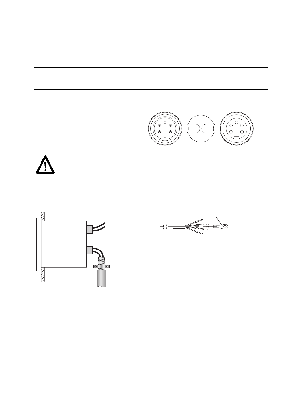
2. Terminal assignment
Pin Assignment Core colour DIN47100
Pin 1 Sensor supply +24 V yellow red
Pin 2 Sensor supply 0 V green black
Pin 3 -- -- --
Pin 4 Tx/Rx+, RS485 brown brown
Pin 5 Tx/Rx-, RS485 white orange
Male connector M16 Female connector M16
3
4
2
1
5
IEC757
3
2
1
4
5
N 141
Connect power supply that is free from interference emission. The supply must not be used as
parallel supply of drives, shields, magnetic valves, etc.
Apply DC according to the terminal assignment
Power supply: 24 VDC ±10 %
Shield
Use shielded cables only. Ground of the shield must be provided at the machine (two examples
corresponding to the cable applied, see drawings).
Abschirmungsanschluss
www.baumer.com 4
Page 5

N 141
3. Interface
3.1. Interface data
Type: RS485
Baudrate: 19200
Parity: No
Data bits: 8
Stop bits: 1
Handshake: No
Redundancy check: Yes (CRC)
Timeout reply*: 0,1...60 ms
BUS switching time**: <0,1 ms
3.2. Protocol
The spindle position display operates with ASCII protocol (clear text protocol). Depending on the command, the
protocol data package varies between 5 and 17 bytes.
Byte Hex-Code Significance Parameters
1 01H SOH = start of heading permanent 01h
2 XXh Adr = address/identifier 00 ... 31dez + 20h Offset (identifier 00 = 20h)
3 XXh Cmd = command code Defined commands
4-n [XXh..XXh] [Data] = data 20h-7Fh
n+1 04h EOT = end of transmission Permanent 04h
n+2 XXh CRC = redundancy check 00h ... FFh
3.3. Redundancy check (CRC byte)
For optimized error-free data transmission the CRC byte is added after the footer token (EOT, end of
transmission) to the string to be transferred. Upon receiving a command the CRC byte transmitted is
crosschecked with the auto-calculated CRC byte.
Algorithm:
1) Reset CRC byte.
2) Rotate CRC byte by 1 bit to the left.
3) Link result to first data byte XOR.
4) Rotate result by 1 bit to the left.
5) Link result to the second data byte XOR.
:
x) Rotate result by 1 bit to the left.
y) Link result to the last data byte (ever 04H) XOR.
z) Add result as CRC after the footer token (04H) to the transmitted string.
Note:
Example:
String less CRC = 01h 20h 43h 04h
CRC-Byte = 0Ah
0000 0000 RL 0000 0000 XOR 0000 0001 (01h) = 0000 0001
0000 0001 RL 0000 0010 XOR 0010 0000 (20h) = 0010 0010
0010 0010 RL 0100 0100 XOR 0100 0011 (43h) = 0000 0111
0000 0111 RL 0000 1110 XOR 0000 0100 (04h) =
Legend: RL = rotate left; XOR = antivalence link
1101 0000 RL 1010 0001 Important: Bit 7 is shifted in bit 0 during rotation
* To avoid bus collisions a minimum timeout reply of 1 ms (default parameter)
is to kept, i.e. the time elapsed between transmitting the last bit of the
query until start transmitting the 1st bit of the SPA response.
The operator should see that due to the minimized timeout reply of 1 ms
the bus switching time after having transmitted the last bit must not exceed
1 ms.
The default parameter of 1 ms can optionally be altered by serial interface
in steps of 0,1 ms within the range of 0,1 ... 60 ms.
Refer to command „x“ (78h).
** The BUS switching time is the time the SPA requires to be ready again for
reception after having replied to the host
0000 1010
= CRC
www.baumer.com 5
Page 6

N 141
3.4. Broadcast commands
Some specific commands are defined as so-called broadcast commands. As soon as the master broadcasts a
command to identifier 99, the command is addressed to every SPA in the network. Each individual spindle
position display will accomplish the respective command but will not respond any confirmation to master.
3.5. Data saving
Specific parameters are saved in EEPROM (1.000.000 writing cycles). Data saving is via interface upon every
parameter transmission to SPA.
Important:
There should not be a cyclic transmission of these parameters to the SPA but only if necessary, for example in
case of parameter alteration. The parameters that are saved in EEPROM are listed in the charts in chapter
“Command explanations” or “Overview on commands”.
4. Command explanations
4.1. General information
The following is describing the individual interface commands broken down into the four groups below:
- operating commands [ commands required during operation ]
- parameter commands [ commands for SPA parameterization ]
- identifier commands [ commands to indicate or alter the device identifier (address)]
- specific commands [ commands for specific functions as device reset or version number readout]
The following abbreviations are applied:
SOH = Start of heading (header token)
EOT = End of transmission (footer token)
Adr = Device address, including offset 20h
Cmd = Command
Data = data transmitted or received
4.2. Operating commands
Command
code
C (43h) 3 / 11 X - - - Check if current value = target
R (52h) 6 X - - - Read current value
T (54h) 7 X - - - Read current value and softkey status
S (53h) 8 X X - X Read / write target
U (55h) 6 X X - - Offset
V (56h) 2 X X X X Read / write profile number
Z (5Ah) 6 X X X X Set preset
t (74h) 6 - X - - Transmit tool number
u (75h) 6 - X - - Transmit optional number sequence
Data amount
inbytes
read write Broad-
cast
Save in
EEPROM
significance
www.baumer.com 6
Page 7

N 141
4.2.1. Check Position, command „C“ (43h)
This command provides the alignment status of target versus current value. If the current value is within the
target tolerance window, the response will be „o“ (6Fh) for OK together with the current profile number. If the
current value is outside the tolerances, „x“ (78H) followed by the current profile number will be replied.
Example: (active profile number = 05)
Transmission
Response if current value within the tolerance window:
Response
Response if current value outside the tolerance window:
Response
SOH Adr Cmd EOT CRC
01h 20h 43h 04h 0Ah
SOH Adr Cmd Status Profile no. = 05 EOT CRC
01h 20h 43h
SOH Adr Cmd Status Profile no. = 05 EOT CRC
01h 20h 43h
6Fh 30h 35h
78h 30h 35h
04h A5h
04h 1D
Extended command Check Position „CX“
The command extension „Check Position CX “provides besides the alignment status target versus current value
also the contents of the status and error register as well as the current value. The profile number is not
transmitted.
Note: SPA N 141 does not provide any status or error register. For reasons of compatibility to other multicon
equipment here the permanent parameter 80h is transmitted, i.e. the 4 data bytes have no significance.
Example:
Transmission
Response
SOH Adr Cmd
01h 20h 43h 58h 04h A8h
SOH Adr Cmd Stat. Status-Reg Error-Reg Current value = -12,50 EOT CRC
01h 20h 43h
SCmd
EOT CRC
6Fh 80h 80h 80h 80h 2Dh 30h 31h 32h 35h 30h
04h B7h
4.2.2. Read parameter current value, command „R“ (52h)
This command is for readout the 6-digit current value (bottom line). The amount of data is always 6 bytes. In
case of a negative value, the “-“ sign (2Dh) together with 5 data bytes is replied. Positive values come as 6 data
bytes without sign. Values of less than 6 (5) digits will come with preceding zeroes.
Example: Current value = -32,50
Transmission
Response
SOH Adr Cmd EOT CRC
01h 20h 52h 04h 40h
SOH Adr Cmd Current value = –32,50 EOT CRC
01h 20h 52h
2Dh 30h 33h 32h 35h 30h
04h 54h
www.baumer.com 7
Page 8

N 141
4.2.3. Read current value and key status, command „T“ (54h)
This command is for readout the 6-digit current value (bottom line of the display) as well as the key status.
Amount of data is always 7 byte. Negative values will come with a “-“ sign (2Dh) together with 5 data bytes.
Positive values are transmitted by 6 data bytes less any sign. Values inferior to 6 (5) digits come with preceding
zeroes. The 7
th
data byte is comprising the key status. A readout operation is deleting the status of the actuated
key (21hex) so that any further readout will always be 20hex. Status 1 (21hex) will not be restored until the key
is actuated again.
Example: Current value = -32,50
Transmission
Response
key = 0
Response
key = 1
SOH Adr Cmd EOT CRC
01h 20h 54h 04h 40h
SOH Adr Cmd Current value = –32,50 key EOT CRC
01h 20h 54h
SOH Adr Cmd Current value = –32,50 key EOT CRC
01h 20h 54h
2Dh 30h 33h 32h 35h 30h 20h
2Dh 30h 33h 32h 35h 30h 21h
04h E2h
04h E0h
4.2.4. Read / write parameter target (profile), command „S“ (53h)
This command is for the presently active target readout or for programming respectively reading a specific
target. The data are composed of profile number (2 bytes) and target (6 bytes). Important: Negative targets
come with 5 digits only (see example no. 3).
Example 1: Read active target (current profile number = 12; target = 12,50)
Transmission
Response
Response upon deletion of all targets:
Response
Example 2: Read target of a specific profile (profile number = 17; target = 12,50)
Transmission
Response
Example 3: Write target of a specific profile (profile number = 17; target = -12,50)
s
Transmission
Response
s
SOH Adr Cmd EOT CRC
01h 20h 53h 04h 2A
SOH Adr Cmd Profile no. = 12 Target = 12,50 EOT CRC
01h 20h 53h
SOH Adr Cmd Profile no. =
01h 20h 53h
SOH Adr Cmd Profile no. = 17 EOT CRC
01h 20h 53h
SOH Adr Cmd Profile no. = 17 Target = 12,50 EOT CRC
01h 20h 53h
SOH Adr Cmd Profile no. = 17 Target = -12,50 EOT CRC
01h 20h 53h
SOH Adr Cmd Profile no. = 17 Target = -12,50 EOT CRC
01h 20h 53h
31h 32 30h 30h 31h 32h 35h 30h
FFh
3Fh 3F 3Fh 3Fh 3Fh 3Fh 3Fh 3Fh
31h 37h
31h 37h 30h 30h 31h 32h 35h 30h
31h 37h 2Dh 30h 31h 32h 35h 30h
31h 37h 2Dh 30h 31h 32h 35h 30h
04h 16h
Target = FFFFFFh EOT CRC
04h 3E
04h 2Ah
04h BCh
04h FBh
04h FBh
www.baumer.com 8
Page 9

N 141
4.2.5. Read / write parameter offset, command „U“ (55h)
This command is to read or write the offset that is added to the true current value. First however the function
must be enabled in command bit parameter ‚a’ (61h).
Example 1: Read offset
Transmission
SOH Adr Cmd EOT CRC
01h 20h 55h 04h 26h
Example 2: Write offset
Transmission
SOH Adr Cmd data (offset = –20,00) EOT CRC
01h 20h 55h
2Dh 30h 32h 30h 30h 30h
04h C3h
Response in both examples:
Response
SOH Adr Cmd data (offset = –20,00) EOT CRC
01h 20h 55h
2Dh 30h 32h 30h 30h 30h
04h C3h
4.2.6. Read / write parameter profile number, command „V“ (56h)
This command is to readout the number of the presently active profile respectively for altering the profile.
Example 1: Read active profile (active profile number = 38)
Transmission
Response
Response after reset upon deletion of all profiles:
Response
Example 2: Transmit new profile (new profile number = 17)
Transmission
Response
Example 3: Transmit new profile by broadcast command to all N 141 (Identifier = 99 (83h); new profile no. =
17)
Transmission
Response Not confirmed
To verify whether the new profile has been accepted by all N141 utilize check command „C“ (43h).
SOH Adr Cmd EOT CRC
01h 20h 56h 04h 20h
SOH Adr Cmd Profile no. = 38 EOT CRC
01h 20h 56h
33h 38h
04h 28h
SOH Adr Cmd Profile no. = FF EOT CRC
01h 20h 56h
3Fh 3Fh
04h 16h
SOH Adr Cmd Profile no. = 17 EOT CRC
01h 20h 56h
31h 37h
04h 3E
SOH Adr Cmd Profile no. = 17 EOT CRC
01h 20h 56h
31h 37h
04h 3E
SOH Adr Cmd Profile no. = 17 EOT CRC
01h 83h 56h
31h 37h
04h 04
www.baumer.com 9
Page 10

N 141
4.2.7. Align current value with preset, command „Z“ (5Ah)
The Z command is for setting the current value to any optional position. The required position value is
transmitted to the SPA. The SPA will calculate a so-called “preset offset” -value relating to the true absolute
sensor position. When calculating the preset offset the already programmed offset transmitted by command “U”
will be considered, so that after having accomplished the “Z” command the current value always equals the
preset.
The current value displayed is composed as follows:
Current value
Current value
Current value
current value displayed and read out by interface
Anz
internal absolute current value.
Abs
Preset offset Offset generated by command „Z“.
Offset Additional offset defined by command „U“. This function however must be enabled in
command bit parameter ‚a’ (61h), otherwise offset = 0.
Example 1: Readout current preset
Transmission
Response
SOH Adr Cmd EOT CRC
01h 20h 5Ah 04h 38h
SOH Adr Cmd Preset = 2,50 EOT CRC
01h 20h 5Ah
30h 30h 30h 32h 35h 30h
Example 2: : Align actual value with preset (preset = 17,25)
Transmission
Response
SOH Adr Cmd Preset = 17,25 EOT CRC
01h 20h 5Ah
SOH Adr Cmd Preset = 17,25 EOT CRC
01h 20h 5Ah
30h 30h 31h 37h 32h 35h
30h 30h 31h 37h 32h 35h
Example 3: Align actual value with preset at all SPAs by broadcast command
Transmission
Response Not confirmed
SOH Adr Cmd Preset = 17,25 EOT CRC
01h 83h 5Ah
30h 30h 31h 37h 32h 35h
4.2.8. Readout parameter tool number, command „t“ (74h)
This command is for displaying a 6-digit tool number in the upper line of the display. The tool number is
indicated without dot respectively comma. Preceding zeroes as well as both direction arrows are suppressed.
The bottom line still indicates the current value.
The number is shown on the display until any command except „t“, „u“, „R“ or “T” is received by interface. The
number will be retained after power failure.
Example: (tool number = 654321)
Transmission
Response
SOH Adr Cmd Tool number = 654321 EOT CRC
01h 20h 74h
SOH Adr Cmd Tool number = 654321 EOT CRC
01h 20h 74h
= current value
Anz
36h 35h 34h 33h 32h 31h
36h 35h 34h 33h 32h 31h
+ Preset offset + Offset
Abs
04h 27h
04h 09h
04h 09h
04h AAh
04h 47h
04h 47h
www.baumer.com 10
Page 11

N 141
4.2.9. Show any optional number sequence in the bottom line of display , command „u“ (75h)
The command is for writing a 6-digit number sequence in the bottom line of the display. The number is indicated
without dot respectively comma. Preceding zeroes as well as both direction arrows are suppressed. The upper
line still indicates the current target or tool number.
The number sequence is displayed until any optional command except „t“, „u“, „R“ or “T” is received by
interface. The number will be retained after power failure.
Example: (number sequence = 123456)
Transmission
Response
SOH Adr Cmd number = 123456 EOT CRC
01h 20h 75h
SOH Adr Cmd number = 123456 EOT CRC
01h 20h 75h
31h 32h 33h 34h 35h 36h
31h 32h 33h 34h 35h 36h
04h BCh
04h BCh
Important:
Command “t” in conjunction with command “u” enables displaying a 12-digit number.
Tool number and number sequence are not saved.
4.3. Parameter commands
Command
code
a (61h) 5 X X - X Read / write general parameters
b (62h) 8 X X - X Parameter: Tolerance compensation, window
c (63h) 8 X X - X Parameter: Scaling factor spindle pitch
i (69h) 1 X X X X Parameter: mm / inch
x (78h) 5 X X - X Read / write specific parameter
4.3.1. Read / write bit parameter, command „a“ (61h)
To exploit maximum memory capacity, several parameters are put together and transferred as “data pack”
under the following parameter codes:
Data1: 1 0 X X 0 X 0 X
┬ ──┬── ─┬─ ─┬─
│ │ │ └─── positioning direction 0/1 (UP/DOWN)
│ │ └─────── counting direction 0/1 (UP/DOWN)
│ └──────────── arrows 0/1/2/3 (UP/DOWN/UNI/OFF)
└──────────────── 1
Data2: 1 0 X X 0 X 0 X
┬ ┬ ─┬─ ─┬─ ─┬─
│ │ │ │ └─── round current value 0/1 (OFF/ON)
│ │ │ └─────── turn display 0/1 (OFF/ON)
│ │ └─────────── offset 0/1/2 (OFF/SER/S+K)
│ └────────────── reserved
└──────────────── 1
Data3: 1 0 0 0 0 0 X X
┬ ────┬──── ─┬─
│ │ └─── hide target 0/1/2 (ON/OFF/EVER)
│ └──────────
└──────────────── 1
Data4/5: 0 0 1 1 X X X X
───┬───
└───── reserved
Data amount
in bytes
read write Broad-
cast
reserved
Save in
EEPROM
Significance
www.baumer.com 11
Page 12

N 141
Note: Only the bits marked ‘X’ may be altered. The permanent parameters „1“ and „0“ must not be altered since
this might create a control token ( tokens < 20h) what is not permitted in ASCII protocol.
Example 1: Read bit parameter (Data1 to Data3 = 80h; Data4 to Data5 = 30h)
Transmission
Response
SOH Adr Cmd EOT CRC
01h 20h 61h 04h 4E
SOH Adr Cmd Data1 Data2 Data3 Data4 Data5 EOT CRC Bit parameter default
01h 20h 61h
80h 80h 80h 30h 30h
04h F1
Example 2: Write bit parameter (positioning direction = Down; turn display = On)
Transmission
Response
SOH Adr Cmd Data1 Data2 Data3 Data4 Data5 EOT CRC
01h 20h 61h
SOH Adr Cmd Data1 Data2 Data3 Data4 Data5 EOT CRC
01h 20h 61h
81h 84h 80h 30h 30h
81h 84h 80h 30h 30h
04h 91h
04h 91h
Explanation of parameter „a“
Positioning direction
This parameter defines the positioning direction to head for the target. Compensating tolerances, for example at
cogwheels, joints, shafts etc during a precise positioning operation requires a tolerance compensation. The
tolerance compensation is proceeded by heading for the target position always from the same direction by socalled loops. Loops mean that the target position is first crossed by a defined distance and then headed for from
the opposite direction. The parameter for the crossing distance is programmed by command “b”. Whether a loop
is required or not can be seen from the direction arrows on the display. A flashing arrow means tolerance
compensation required. Upon reaching the turning point the direction changes and the arrow stops flashing. A
target enabling direct positioning is marked by a non-flashing arrow. Upon reaching the target within the
programmed tolerances (see command “b”) the arrows will not disappear until the required tolerance
compensation was completed.
00 = Up Direct positioning if target position > current position; otherwise proceed tolerance compensation
01 = Down Direct positioning if target position < current position; otherwise proceed tolerance compensation
Counting mode
This parameter assigns either „ascending“ or „descending” counted values in relation to the shaft’s direction of
rotation. Following parameters are available:
00 = Up Clockwise rotation, ascending counted values
01 = Down Clockwise rotation, descending counted values
Arrows
This parameter relates to the arrows in the display that indicate the operator the correct direction (to the right or to
the left) of the new positioning operation. The following parameters are available:
00 = Up If current value < target = arrow to the right; current value > target = arrow to the left
01 = Down As „Up“, but inverted direction of the arrows
10 = Uni If current value ≠ target indicate both arrows
11 = Off Ever hide arrows
Rounding the current value
This means that the current value being within the tolerances but still differing from the target is rounded up or
down to the target value as soon as the shaft remains idle for approx. 3 seconds. The rounding operation is only
visual, the true internal current value remains unchanged. For current value readout by serial interface (command
“R”) the true, not rounded current position value is provided. The true current value will immediately reappear on
the display upon actuating a key. If the position is still within the tolerance window the rounding operation will be
repeated after 3 seconds.
Note: In operating mode „Hide target = Ever“ the target is deactivated and the SPA serves as a pure current
value display with disabled rounding function. The following parameters are available:
0 = Off Rounding the current value disabled
1 = On Rounding the current value enabled
www.baumer.com 12
Page 13

N 141
Turn display
This parameter turns the display by 180°.
0 = Off Display readout with standard mounting, i.e. display above keypad
1 = On Display readout with inverted mounting, i.e. display below keypad
Offset
Command „U“ is for programming the offset that is added to the current value and current target. This parameter
defines whether the offset is considered in the calculation.
Parameter 2 means optional manual offset alteration directly at the device itself. Press both softkeys at the same
time and proceed offset alteration by turning the shaft. Press the softkeys anew to quit. The bottom line shows
the unchanged current value again. The value alteration emerging from the shaft turn has been assigned to the
offset.
0 = Off Offset disabled. The previous offset transmitted -if any- is neither added to current value nor
target
1 = SER Offset enabled. Offset is added to the actual current value.
Offset alteration by serial interface
2 = S+K Offset enabled. The offset is added to the actual current value.
Offset alteration either by serial interface or manually at the device.
Hide target
This parameter defines when to indicate the target in the upper line of the display.
0 = On Ever indicate target if target ≠ current value
1 = Off Ever indicate target, even if target = current value. Indicate also arrows if target ≠ current value.
2 = Ever Ever hide both target and arrows.
4.3.2. Read /write parameter spindle tolerance and tolerance window, command „b“ (62h)
This command is for reading or writing the parameters tolerance compensation and tolerance window.
Example 1: Read parameter (tolerance compensation = 0,15; tolerance window = 0,25)
Transmission
Response
Example 2: Write parameter (tolerance compensation = 1,30; tolerance window = 5,00)
Transmission
Response
SOH Adr Cmd EOT CRC
01h 20h 62h 04h 48h
SOH Adr Cmd Tolerance compensation=0,15 Tolerance window=0,25 EOT CRC
01h 20h 62h
SOH Adr Cmd Tolerance compensation=1,30 Tolerance window=5,00 EOT CRC
01h 20h 62h
SOH Adr Cmd Tolerance compensation =1,30 Tolerance window=5,00 EOT CRC
01h 20h 62h
30h 30h 31h 35h 30h 30h 32h 35h
30h 31h 33h 30h 30h 35h 30h 30h
30h 31h 33h 30h 30h 35h 30h 30h
04h AAh
04h 20h
04h 20h
www.baumer.com 13
Page 14

N 141
4.3.3. Read / write parameter spindle pitch (scaling factor), command „c“ (63h)
This command is utilized to read or write the scaling factor of the spindle pitch within the range from
0,0000001...9,9999999. The decimal point is not transmitted.
How to calculate the scaling factor:
Resolution per turn: 23,04 mm
Spindle pitch: 4,00 mm
Spindle pitch 4,00
Scaling factor = ───────────────── = ───── = 0,1736111
Resolution per turn 23,04
Example 1: Read scaling factor (scaling factor = 1,000000)
Transmission
Response
SOH Adr Cmd EOT CRC
01h 20h 63h 04h 4Ah
SOH Adr Cmd Scaling factor = 1,0000000 EOT CRC
01h 20h 63h
31h 30h 30h 30h 30h 30h 30h 30h
04h 4B
Example 2: Write scaling factor (scaling factor = 0,1736111)
Transmission
Response
SOH Adr Cmd Scaling factor = 0,1736111 EOT CRC
01h 20h 63h
SOH Adr Cmd Scaling factor = 0,1736111 EOT CRC
01h 20h 63h
30h 31h 37h 33h 36h 31h 31h 31h
30h 31h 37h 33h 36h 31h 31h 31h
04h 05h
04h 05h
4.3.4. Read / write parameter measuring unit, command „i“ (69h)
The command is to read or write the measuring unit in mm or inches.
Data = 0 (30h) = mm
Data = 1 (31h) = inch
Example 1: Read parameter (setting = mm)
Transmission
Response
Example 2: Change measuring unit to inches
Transmission
Response
Example 3: Write mm as measuring unit into all SPAs by broadcast command (identifier/Adr=99)
Transmission
Response Not confirmed
Important: The parameter is programmed in mm and converted into inches by the SPA when displaying the
position values.
SOH Adr Cmd EOT CRC
01h 20h 69h 04h 5E
SOH Adr Cmd Data EOT CRC
01h 20h 69h
SOH Adr Cmd Data EOT CRC
01h 20h 69h
SOH Adr Cmd Data EOT CRC
01h 20h 69h
SOH Adr Cmd Data EOT CRC
01h 83h 69h
30h
31h
31h
30h
04h D0h
04h D2
04h D2
04h CDh
www.baumer.com 14
Page 15

N 141
4.3.5. Read / write specific parameter „x“ (78h)
The specific parameter „x“ comprises several sub-parameters enabling alteration of originally permanent
parameters to adapt them to new circumstances. At present, the following sub-parameter is available:
D (44h) = minimized delay time of serial interface
Sub parameter: Delay time „D“ (44h)
This parameter defines the minimum delay time (timeout) between the last bit received and the first bit of the
response transmitted. Delay time is in steps of 0,1 ms within the range from 00.0 ... 60,0 ms. Default is 1,0 ms.
Example 1: Read current delay time
Transmission
Response
SOH Adr Cmd Sub EOT CRC
01h 20h 78h 44h 04h 7Ch
SOH Adr Cmd Sub Delaytime = 4.5 EOT CRC
01h 20h 78h 44h
30h 30h 34h 35h
04h BBh
Example 2: Write new delay time
Transmission
Response
SOH Adr Cmd Sub Delaytime = 15.0 EOT CRC
01h 20h 78h 44h
SOH Adr Cmd Sub Delaytime = 15.0 EOT CRC
01h 20h 78h 44h
30h 31h 35h 30h
30h 31h 35h 30h
04h BDh
04h BDh
Please note that the true delay time might be extended. It depends on the required processing time as well as
on internal software cycles. The tolerance window is approx. 8 ms.
4.4. Identifier commands
Command
code
A (41h) 2 X X X X Assign or indicate identifier
B (42h) 2 - - - - SPA response in adressing mode
4.4.1. Assigning device identifiers in the network, command „A“ (41h)
This command is creating an automated process where the device identifier is assigned in successive order to
every single SPA upon commissioning of the system. The first identifier to be assigned is broadcasted to all
networked SPAs as follows:
Transmission
All SPAs now show the identifier just transmitted and that is to be assigned in the upper line of the display. The
bottom line indicates the device-specific identifier. To enter the new identifier, the shaft of the respective SPA
has to be turned by half at least (direction does not matter). The identifier is now entered and appears in the
lower line of the display (as device-specific identifier). Both identifiers are now identical. As soon as the shaft is
in idle position again and after having elapsed 3 seconds, the following confirmatory command „B“ (42h) is
transmitted by SPA to master:
Transmission
to Master
The Master may now transmit command „A“ with the next identifier to be assigned as previously described.
This way, the different (successive) identifiers are automatically assigned.to all networked SPAs, one after the
other.
Important: The confirmatory command „B“ transmitted by SPA to master will be repeated after 3 seconds
provided the master has not previously transmitted another „A“ command.
Data amount
In bytes
SOH Adr Cmd Identifier = 01 EOT CRC
01h 83h 41h
SOH Adr Cmd Identifier = 01 EOT CRC
01h 21h 42h
read write Broad-
30h 31h
30h 31h
cast
04h B4h
04h 86h
Save in
EEPROM
Function
www.baumer.com 15
Page 16

N 141
Indicate identifier in the display, command „A“ (41h)
This command less parameters as a broadcast command (address/identifier=99) will make every networked
SPA indicate the device-specific identifier in the bottom line of the display. The upper line is blind.
This command is a desginated broadcast command.
Transmission
Response Not confirmed
SOH Adr Cmd EOT CRC
01h 83h 41h 04h 80h
The SPA remains in this mode until being switched off and on again or until transmission of another command.
Extended identifier command „AX“ (41h,58h)
This extended command is utilized for addressing individual multicon devices in the bus network in a similar
way as described above. By broadcast command the identifier to be assigned is transmitted to all networked
devices as follows:
Transmission
Response Not confirmed
SOH Adr Cmd Sub identifier = 01 EOT CRC
01h 83h 41h 58h
30h 31h
04h 40h
Similar to standard command all devices now show the identifier just transmitted and that is to be assigned in
the upper line. Entering the identifier is proceeded the same way. However contrary to the above no
confirmatory command „B“ will be replied. It is up to master to check whether the identifier has been accepted,
for example by command “R” (read current value). The R-command is transmitted under the corresponding
identifier to the position display. If the addressed SPA is responding the assignment was successful and the
master can proceed with the next identifier. Regarding other commands the display of the respective device
switches to standard operation.
4.5. Specific commands
Command
code
K (4Bh) - - X X X Specific command: Profile reset (delete)
Q (51h) 1 - X X X Specific command: N 141 reset
X (58h) 2 / 4 / 8 X - - - Specific commands
4.5.1. SPA profile reset, command „K“ (4Bh)
This command is deleting all previously programmed profiles.
Example 1: Profile reset at specific N 141
Transmission
Response
Example 2: Profile reset at all N 141 by broadcast command (Identifier=99)
Transmission
Response Not confirmed
Important: After profile reset all profile data are set to auf FFFFFFhex , the current profile number to FFhex.
The display now shows 6 dashes instead of the target.
Data
amount in
read write Broad-
cast
Save in
EEPROM
Significance
bytes
SOH Adr Cmd Data EOT CRC
01h 20h 4Bh
SOH Adr Data EOT CRC
01h 20h
SOH Adr Cmd Data EOT CRC
01h 83h 4Bh
6Fh
04h C6h
7Fh
04h 52h Device replies by standard response ‚o’ (6Fh) = OK
04h DBh
7Fh
www.baumer.com 16
Page 17

N 141
www.baumer.com 17
Page 18

N 141
4.5.2. N 141 restore default, command „Q“ (51h)
This command restores default either of individual or collective parameters.
Data = p (70h) = clear offset. Tool radius is again 0,00
Data = q (71h) = restore default
Data = t (74h) = Device identifier = 98
Data = x (78h) = Multiturn counter is set to 4096 corresponding to 0.
Data = ∆ (7Fh) = All above functions are enabled.
Note: No profile reset. Profile reset by command „R“.
Example 1: Restore default at specific N 141
Transmission
Response
SOH Adr Cmd Data EOT CRC
01h 20h 51h
7Fh
04h AEh
SOH Adr Data EOT CRC
01h 20h
04h 52h Device replies by standard response ‚o’ (6Fh) = OK
6Fh
Example 2: Restore default at all N 141 by broadcast command (identifier = 99)
Transmission
SOH Adr Cmd Data EOT CRC
01h 83h 51h
7Fh
04h B3
Response Not confirmed
4.5.3. Read version, device type or serial number, command „X“ (58h)
This command is for reading version number, device type or serial number. The following sub-commands are
available:
Data = V (56h) = read version
Data = T (54h) = read device type
Data = S (53h) = read serial number
Example 1: Read version
Transmission
Response
Example 2: Read device type (device type = N 141; software no. = 01)
Transmission
Response
Code configuration of the transmitted device type:
1 0 0 0 0 0 0 1 1 0 0 0 0 0 0 1 = 81 81 hex
┬ ──────┬────── ┬ ───────┬─────
│ │ │ └─────── software no. 01h = software 01
│ │ └──────────────── permanent 1
│ └────────────────────────── device type 01h = N 141
└────────────────────────────────── permanent 1
SOH Adr Cmd Data EOT CRC
01h 20h 58h
56h
04h D8h
SOH Adr Cmd Data Version number = 2.00 EOT CRC
01h 20h 58h 56h
20h 32h 30h 30h
04h FAh
SOH Adr Cmd Data EOT CRC
01h 20h 58h
54h
04h DCh
SOH Adr Cmd Data Typ EOT CRC
01h 20h 58h 54h
81h 81h
04h 6Eh
www.baumer.com 18
Page 19

N 141
Example 3: Read serial number
Transmission
Response
Code configuration of the transmitted serial number:
SOH Adr Cmd Data EOT CRC
01h 20h 58h
53h
04h D2h
SOH Adr Cmd Data Serial number code = 15830EA4 EOT CRC
01h 20h 58h 53h
31h 35h 38h 33h 30h 3Eh 3Ah 34h
04h 63h
The Low-Nibble (lower 4 bits of a byte) of the 8 data bits received equal together a 4 byte value comprising the
serial number.
The serial number is composed by date and time of production. Due to also the seconds being coded and by
assigning only one number per second the serial number is unique.
Example: Serial number for June 1st, 2005 / 01.06.2005 16:58:36 = 15 83 0E A4 hex
X X X X X X X X X X X X X X X X X X X X X X X X X X X X X X X X Bit position
J J J J J J M M M M T T T T T h h h h h m m m m m m s s s s s s contents
0 0 0 1 0 1 0 1 1 0 0 0 0 0 1 1 0 0 0 0 1 1 1 0 1 0 1 0 0 1 0 0 ex.= 15 83 0E A4 hex
─────┬───── ────┬──── ────┬──── ─────┬───── ──────┬────── ─────┬─────
│ │ │ │ │ └─────── sec. 0
│ │ │ │ └──────────────────── min.11
│ │ │ └───────────────────────────────── hours 1
│ │ └──────────────────────────────────────────── day 0
│ └────────────────────────────────────────────────────── month
└───────────────────────────────────────────────────────────────── year 00
│
01.06.05 16:58:36 <──────┘
0100 = 24h= 36d
1010 = 3Ah= 58d
0000 = 10h= 6d
0001 = 01h= 01d
0110 = 06h= 06d
0101= 05h= 05d
www.baumer.com 19
Page 20

N 141
5. Error warnings
5.1. CRC error
Upon recognizing a CRC error in a transmitted command the SPA will respond as follows:
Response
SOH Adr Error EOT CRC
01h 20h 65h 04h 46h Error = „e“ (65h) = CRC error
5.2. Format error
Upon recognizing a format error (incorrect length of protocol or void command Cmd) in a transmitted command
the SPA will respond as follows.
Response
SOH Adr Error EOT CRC
01h 20h 66h 04h 40h Error = „f“ (66h) = Format error
6. Overview on commands
The following chart shows in alphabetical order all available commands (Cmd) as well as options regarding read
and write (parameterization).
Command
code
a (61h) 5 X X - X Read / write general parameters
b (62h) 8 X X - X Parameter: Tolerance compensation, window
c (63h) 8 X X - X Parameter: scaling factor spindle pitch
i (69h) 1 X X X X Parameter: mm / inch
t (74h) 6 - X - - Transmit tool number
u (75h) 6 - X - - Transmit optional number sequence
x (78h) 5 X X - X Read / write specific parameters
A (41h) 2 X X X X Assign or indicate device identifier
C (43h) 3 / 11 X - - - Check if current value = target
K (4Bh) - - X X X Specific command: Profile reset (delete)
Q (51h) 1 - X X X Specific command: N 141 reset
R (52h) 6 X - - - Read current value
S (53h) 8 X X - X Read / write target
T (54h) 7 X - - - Read current value and key button status
U (55h) 6 X X - - offset
V (56h) 2 X X X X Read / write profile number
X (58h) 2 / 4 / 8 X - - - Specific parameters
Z (5Ah) 6 X X X X Set preset
Data amount
in bytes
read write Broad-
cast
Save in
EEPROM
Signficance
www.baumer.com 20
Page 21

7. Technical data
Technical data – electrical ratings
Supply voltage range 24 VDC ±10 %
Current consumption ≤30 mA
Display LCD, 7-segment display, 2-lines, backlit
Measuring principle Absolute multiturn sensing
Measuring range -999,99...+9999,99 mm
-99.999...+999.999 inch
Steps per turn 2304
Number of turns 4096 / 12 bit
Spindle pitch ≤23 mm
Interface RS485 (ASCII-protocol)
Data memory Parameter buffer: EEPROM
Current value buffer: >10 years by
integrated 3 V lithium battery
Programmable parameters Display position horizontal/vertical
Measuring unit mm/inch
Counting direction
Spindle pitch
Spindle tolerances
Positioning direction
Direction arrows
Tolerance window
Round up/down
Standard DIN EN 61010-1 Protection II
Overvoltage category II
Pollution degree 2
Emitted interference DIN EN 61000-6-3
Interference immunity DIN EN 61000-6-2
Approvals UL/cUL
Technical data – mechanical design
Hollow shaft ø20 mm, ø25 mm
Operating speed ≤600 rpm (short-term)
Protection DIN EN 60529 IP 65 (housing), IP 40 (connector)
Operating temperature -10...+50 °C
Storage temperature -20...+70 °C
Relative humidity 80 % not condensing
Torque support Torque pin provided at housing
Connections - Cable output (30 cm) with male and mating connector M16, 5-pins
Housing type Surface-mount with hollow shaft
Dimensions W x H x L 56 x 100 x 62.5 mm
Mounting Surface-mount with hollow shaft
Weight approx. 200 g
Material Polycarbonate black, UL 94V-0
N 141
www.baumer.com 21
Page 22

7.1. Dimensions
25 H7
(20 H7)
58.5
Fixing pin
for bore
Ø
100
10 mm
40 ±0.2
37
Ø
Hollow shaft Ø25 mm
7
8
20°
M5
37
Ø
Hollow shaft
Ø
20 mm
N 141
M5
37
Ø
6
10
16
56
1
62.5 21.5
8. Part number
Reference Interface
1 RS485
Connection
0 cable output with connector M16
supply voltage
3 24 VDC
Hollow shaft
A ø25 mm
B ø20 mm
N 141.1 0 3 A 01
4
8.5
M16-female
connector
M16
connector
www.baumer.com 22
 Loading...