

Page 1

User´s Guide
LXC cameras (Camera Link®)
Document Version: v1.3
Release: 07.11.16
Document Number: 11160995
Page 2

2
Page 3

Table of Contents
1. General Information ................................................................................................. 6
2. General safety instructions ..................................................................................... 7
3. Intended Use ............................................................................................................. 7
4. General Description ................................................................................................. 7
5. Camera Models ......................................................................................................... 8
5.1 LXC – Camera ........................................................................................................ 8
5.2 Dimensions ............................................................................................................. 9
5.3 Lens Mount Adapter .............................................................................................. 10
5.4 Flange Focal Distance .......................................................................................... 12
6. Installation .............................................................................................................. 12
6.1 Environmental Requirements ................................................................................ 12
6.2 Heat Transmission ................................................................................................ 13
6.2.1 Emergency shutdown at Overtemperature ..................................................... 14
6.3 Mechanical Tests ................................................................................................... 15
7. Process- and Data Interface .................................................................................. 16
7.1 Pin-Assignment Interface ...................................................................................... 16
7.2 Pin-Assignment Power Supply and Digital-IOs ..................................................... 16
7.3 Power saving Mechanisms ................................................................................... 17
7.4 LED Signaling ....................................................................................................... 18
8. ProductSpecications .......................................................................................... 19
8.1 Sensor Specications ........................................................................................... 19
8.1.1 Quantum Efciency of Baumer LXC Cameras ............................................... 19
8.1.2 Shutter ............................................................................................................ 20
8.1.3 Digitization Taps ............................................................................................ 20
8.1.4 Field of View Position ..................................................................................... 21
8.2 Timings .................................................................................................................. 22
8.2.1 Free Running Mode ........................................................................................ 22
8.2.2 Trigger Mode .................................................................................................. 23
9. Software .................................................................................................................. 27
9.1 Frame grabber with GenCP support ..................................................................... 27
9.2 Frame grabber without GenCP support ................................................................ 27
3
Page 4

10. Camera Functionalities .......................................................................................... 28
10.1 Image Acquisition ................................................................................................ 28
10.1.1 Image Format ............................................................................................... 28
10.1.2 Pixel Format ................................................................................................. 29
10.1.3 Exposure Time.............................................................................................. 31
10.1.4 PRNU / DSNU Correction (FPN - Fixed Pattern Noise) ............................... 31
10.1.5 HDR .............................................................................................................. 32
10.1.6 Look-Up-Table .............................................................................................. 32
10.1.7 Gamma Correction ....................................................................................... 33
10.1.8 Region of Interest (ROI) and Multi ROI ........................................................ 33
10.1.9 Multi-ROI ...................................................................................................... 34
10.1.10 Binning ....................................................................................................... 35
10.1.11 Decimation (sub-sampling) ......................................................................... 36
10.1.12 Brightness Correction (Binning Correction) ................................................ 37
10.2 Color Adjustment – White Balance ..................................................................... 37
10.2.1 User-specic Color Adjustment .................................................................... 37
10.2.2 One Push White Balance ............................................................................. 37
10.3 Analog Controls ................................................................................................... 38
10.3.1 Offset / Black Level ....................................................................................... 38
10.3.2 Gain .............................................................................................................. 38
10.4 Pixel Correction ................................................................................................... 39
10.4.1 General information ...................................................................................... 39
10.4.2 Correction Algorithm ..................................................................................... 39
10.4.3 Add Defect Pixel / Defect Columns / Defect Rows to Defect pixel list .......... 40
10.5 Sequencer ........................................................................................................... 41
10.5.1 General Information ...................................................................................... 41
10.5.2 Baumer Optronic Sequencer in Camera xml-le .......................................... 42
10.5.3 Examples ...................................................................................................... 42
10.5.4 Capability Characteristics of Baumer GAPI Sequencer Module .................. 43
10.5.5 Double Shutter ............................................................................................. 44
10.6 Process Interface ................................................................................................ 45
10.6.1 Digital I/O ...................................................................................................... 45
10.7 Trigger Input / Trigger Delay ............................................................................... 47
10.7.1 Trigger Source .............................................................................................. 48
10.7.2 Debouncer .................................................................................................... 49
10.7.3 Flash Signal .................................................................................................. 49
10.7.4 Timer............................................................................................................. 50
10.8 User Sets ............................................................................................................ 51
10.9 Factory Settings .................................................................................................. 51
11. Camera Link
®
Interface ........................................................................................... 52
11.1 Channel Link and LVDS Technology ................................................................... 52
11.2 Camera Signals ................................................................................................... 52
11.2.1 Serial Communication ................................................................................... 52
11.2.2 Camera Control ............................................................................................ 53
11.2.3 Video Data .................................................................................................... 53
11.3 Camera Link
®
Taps .............................................................................................. 55
11.3.1 Tap Conguration ......................................................................................... 55
11.3.2 Tap Geometry ............................................................................................... 55
11.4 Chunk Data ......................................................................................................... 57
4
Page 5

12. Cleaning .................................................................................................................. 58
12.1 Sensor ................................................................................................................. 58
12.2 Cover glass ......................................................................................................... 58
12.3 Housing ............................................................................................................... 58
13. Transport / Storage ................................................................................................ 59
14. Disposal .................................................................................................................. 59
15. Warranty Information ............................................................................................. 59
16. Conformity .............................................................................................................. 60
16.1 CE ....................................................................................................................... 60
17. Support .................................................................................................................... 60
5
Page 6

1. General Information
Thanks for purchasing a camera of the Baumer family. This User´s Guide describes how
to connect, set up and use the camera.
Read this manual carefully and observe the notes and safety instructions!
Target group for this User´s Guide
This User's Guide is aimed at experienced users, which want to integrate camera(s) into
a vision system.
Copyright
Any duplication or reprinting of this documentation, in whole or in part, and the reproduc-
tion of the illustrations even in modied form is permitted only with the written approval of
Baumer. This document is subject to change without notice.
Classicationofthesafetyinstructions
In the User´s Guide, the safety instructions are classied as follows:
Notice
Gives helpful notes on operation or other general recommendations.
Caution
Pictogram
Indicates a possibly dangerous situation. If the situation is not avoided,slight
or minor injury could result or the device may be damaged.
6
Page 7

2. General safety instructions
1
2
3
4
5
Observe the the following safety instruction when using the camera to avoid any damage
or injuries.
Caution
Provide adequate dissipation of heat, to ensure that the temperature does
not exceed +50 °C (+122 °F).
The surface of the camera may be hot during operation and immediately
after use. Be careful when handling the camera and avoid contact over a
longer period.
3. Intended Use
The camera is used to capture images that can be transferred over Camera Link® interfaces to a PC.
Notice
Use the camera only for its intended purpose!
For any use that is not described in the technical documentation poses dangers and will
void the warranty. The risk has to be borne solely by the unit´s owner.
4. General Description
No. Description No. Description
LXC-20 / 40
C-mount only
1
LXC-120 / 200 / 250
lens mount (M58), adapter for
other lens mounts available
Camera Link
2
(Base)
®
socket
4 Signaling LED
Camera Link® socket
5
(Medium / Full / EightyBit)
3 Power Suppy / Digital-IO
7
Page 8

5. Camera Models
5.1 LXC – Camera
LXC-20M / C
LXC-40M / C
LXC-120M / C
LXC-200M / C
LXC-250M / C
Camera Type
Monochrome / Color
LXC-20M / C
LXC-40M / C
LXC-120M / C
LXC-200M / C
LXC-250M / C
Sensor
Size
2/3"
1"
APS-C
35 mm
APS-H
Resolution
2048 × 1088
2048 × 2048
4096 × 3072
5120 × 3840
5120 × 5120
Full Frames
[max. fps]
337
180
63
32
32
8
Page 9

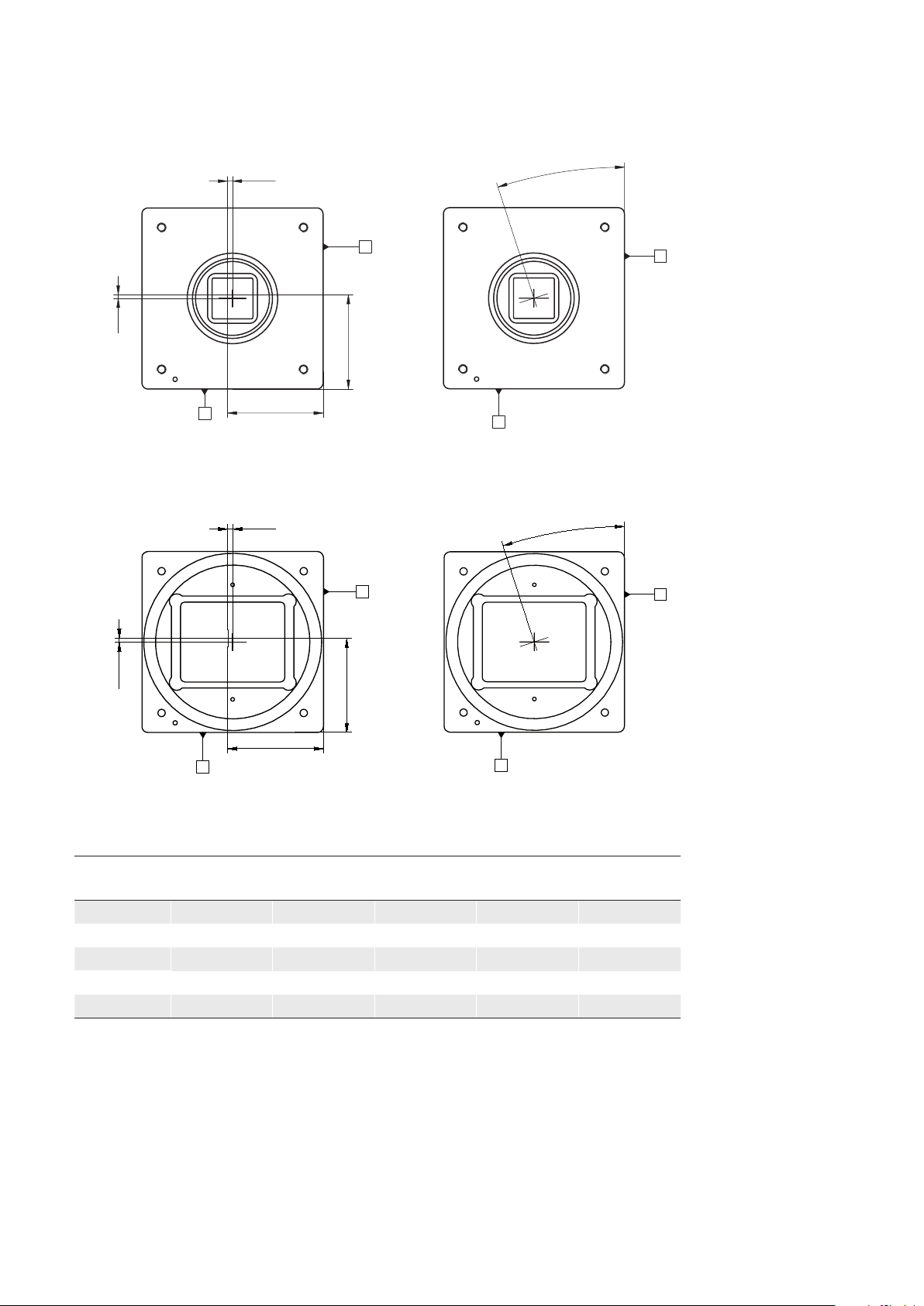
5.2 Dimensions
8
8
LXC-20M / C, LXC-40M / C
26
30
1"-32 UN
60
47
Pixel 0,0
4 x M3 x 6
18,035 ±0,025
47
60
47,95
43,05
38,45
8
4,9
17,5
26
17,5
8
26
8 x M3 x 6
48,8
20
14,7
19,2
LXC-120M / C, LXC-200M / C, LXC-250M / C
60
47
47
M58 x 0,75
Pixel 0,0
4 x M3 x 6
12 ±0,025
60
47,95 / *)50,02
43,05 / *)45,12
38,3
38,45 / *)40,52
8
26
17,5
26
17,5
8
26
8 x M3 x 6
20
48,8
19,2
*)
LXC-250
14,7
◄Figure1
Dimensions of the
Baumer LXC cameras
9
Page 10

5.3 Lens Mount Adapter
20,75
59ø
M58x0,75
M42x1
3
ø
50
Notice
LXC-20 and LXC-40 have a C-Mount interface only.
Adapter M58 / F-mount
(Art. No.: 11117852)
59ø
F-Mount
M58x0,75
40,43
Adapter M58 / M42x1-mount (26.8mm)
(Art. No.: 11127232)
10
Notice
ange focal distance: 27 mm, ±0,25 mm
suitable for Zeiss M42 lenses (e.g. Biogon T* 2.8/21 Z-M42-I, Biogon T* 2/35 Z-M42-I,
C Sonnar T* 1.5/50 Z-M42-I)
Page 11

Adapter M58 / M42x1-mount (45.5 mm)
(Art. No: 11137781)
59ø
M42x1
39,43
M58x0,75
50
ø
3
Notice
suitable for Zeiss (e.g. Distagon T* 2/25 Z-M42-I, Planar T* 1.4/50 Z-M42-I, Makro-Planar
T* 2/50 Z-M42-I) and KOWA M42 lenses (e.g. LM28LF P-Mount, LM35LF P-Mount)
Adapter M58 / C-mount
(Art. No: 11115198)
59ø
30ø
C-Mount
M58x0,75
50
4,467
3ø
11
Page 12

5.4 Flange Focal Distance
12 ±0,25
6. Installation
Lens mounting
Notice
Avoid contamination of the sensor and the lens by dust and airborne particles when
mounting the support or the lens to the device!
Therefore the following points are very important:
▪ Install the camera in an environment that is as dust free as possible!
▪ Keep the dust cover (foil) on camera as long as possible!
▪ Hold the print with the sensor downwards with unprotected sensor.
▪ Avoid contact with any optical surface of the camera!
6.1 Environmental Requirements
Temperature
Storage temperature -10 °C ... +70 °C ( +14 °F ... +158 °F)
Operating temperature* see Heat Transmission
* If the environmental temperature exceeds the values listed in the table below, the cam-
era must be cooled. (see Heat Transmission)
Humidity
Storage and Operating Humidity 10 % ... 90 %
Non-condensing
12
Page 13

6.2 Heat Transmission
Caution
Provide adequate dissipation of heat, to ensure that the temperature does
not exceed +50 °C (+122 °F) at temperature measurment point T.
The surface of the camera may be hot during operation and immediately
after use. Be careful when handling the camera and avoid contact over a
longer period.
As there are numerous possibilities for installation, Baumer do not speciy
a specic method for proper heat dissipation, but suggest the following principles:
▪ operate the cameras only in mounted condition
▪ mounting in combination with forced convection may provide proper heat
dissipation
T
Measure Point Maximal Temperature
T 50°C (122°F)
For remote temperature monitoring of the camera a temperature sensor is integrated.
Notice
The temperature sensor is able to deliver values of 0°C (32°F) to +85°C (185°F)
T
◄Figure2
Temperature measure-
ment points of Baumer
LXC cameras
Take care that the temperature of the camera does not exceed the specied case temperature +50°C (+122°F).
13
Page 14

6.2.1 Emergency shutdown at Overtemperature
To prevent damage on the hardware due to high temperatures, the camera is equipped
with an emergency shutdown. The DeviceTemperatureStatusTransitionSelector feature
allows you to select different thresholds for temperatures:
NormalToHigh: freely programmable value
HighToExeeded: xed value (camera shutdown if exceeded)
ExeededToNormal: freely programmable value, temperature for error-free re-ac
tivation of the camera.
In the DeviceTemperatureStatusTransition feature, the temperatures for the programma-
ble temperature transitions are set.
The Event EventDeviceTemperatureStatusChanged is always generated when Device-
TemperatureStatus changes.
If the temperature rises above the value set at HighToExeeded, the DeviceTemperature-
Exceeded feature is set to True, the image recording is stopped, and the LED is set to red.
For further use, the camera must disconnected from the power supply after cooling down
or a device reset should be carried out.
The sufcient cooling is recognizable when the event EvenDeviceTemperatureStatusChanged (Device Temperature < ExceededToNormal) is output.
14
Page 15

6.3 Mechanical Tests
Tested with C-Mount adapter adapter and lens dummy.
Environmental
Testing
Vibration,
sinussodial
Vibration, broad
band
Shock IEC 60068-2-27 Puls time 11 ms / 6 ms
Bump IEC60068-2-29 Pulse Time 2 ms
Standard Parameter
IEC 60068-2-6 Search for
Resonance
Amplitude underneath crossover frequencies
Acceleration 1 g
Test duration 15 min (axis)
IEC 60068-2-64 Frequency
range
Acceleration 10 g
Test duration 300 min (axis)
Acceleration 50 g / 100 g
Acceleration 100 g
10-2000 Hz
0,75 mm
45 min (total)
10-1000 Hz
15 h (total)
15
Page 16

7. Process- and Data Interface
Baumer
Type: XXXXXx
(xxxxxxx)
CL FULL
CL BASE
7
3
7.1 Pin-Assignment Interface
Notice
The camera has two Camera Link® sockets. To differentiate between
Camera Link® socket, please look at the label.
You can not use the CL Medium / Full / EightyBit socket alone!
Notice
To use Power over
Camera Link® (PoCL,
12V DC ± 20%), both
Camera Link® sockets
must be used.
Camera Link
(Base)
®
Camera Link
(Medium / Full / EightyBit)
®
Pin Signal Pin Signal Pin Signal Pin Signal
1 GND 14 GND 1 GND 14 GND
2 X0- 15 X0+ 2 Y0- 15 Y0+
3 X1- 16 X1+ 3 Y1- 16 Y1+
4 X2- 17 X2+ 4 Y2- 17 Y2+
5 XCLK- 18 XCLK+ 5 YCLK- 18 YCLK+
6 X3- 19 X3+ 6 Y3- 19 Y3+
7 SERTC+ 20 SERTC- 7 100 Ω term. 20 100 Ω term.
8 SERTFG- 21 SERTFG+ 8 Z0- 21 Z0+
9 CC1- 22 CC1+ 9 Z1- 22 Z1+
10 CC2+ 23 CC2- 10 Z2- 23 Z2+
11 CC3- 24 CC3+ 11 ZCLK- 24 ZCLK+
12 CC4+ 25 CC4- 12 Z3- 25 Z3+
13 GND 26 GND 13 GND 26 GND
16
7.2 Pin-Assignment Power Supply and Digital-IOs
Power Supply / Digital-IOs
M8 / 8 pins (SACC-DSI-M8FS-8CON-M10-L180 SH)
4
5
6
1 (white) not in use
2 (brown) Power VCC +
3 (green) IN 1 (line 0)
4 (yellow) IO GND
5 (grey) IO Power VCC
6 (pink) OUT 1 (line 1)
7 (blue) Power GND
8 (red) not in use
Power Supply
Power VCC 12 VDC ... 24 VDC
2
8
1
Page 17

7.3 Power saving Mechanisms
The camera is equipped with various power saving mechanisms to reduce the power
consumption and to prevent excessive heating.
1. Set the sensor into idle state
If no frame is requested for a specic time (idle time), the sensor is set into idle state. This
reduces the power consumption of the camera.
The sensor is not set into idle state:
▪ in Sequencer Mode
▪ in Burst Mode
▪ at set Acquisition Frame Rate
Trigger (valid)
A
Exposure
B
Readout
C
Idle
DD
Time
A - Trigger delay
B - Exposure time
C - Readout time
D - Idle time
2. Dynamic adjustment of the framerate
The frame rate is dynamically adjusted to the current situation. This means that only so
many frames are recorded, as can be transferred via the interface with the current settings (e.g. resolution, binning and pixel format).
This dynamic adjustment only works when the feature Acquisition Frame Rate is deactivated, so the camera takes pictures at FreeRunning Mode.
Power saving diagram
10
9
8
7
6
power consumption [W]
5
4
0510 15 20 25
framerate [fps]
without power saving
with power saving
Notice
The diagram applies for a low exposure time. As the exposure time increases, the power consumption of the camera increases even with small framerate.
17
Page 18

LED position
7.4 LED Signaling
LED
Figure3►
Signal Meaning
green on Power on, link good
green blinking Power on, no link
red on Error / Overtemperature
LED
Boot process
or
red blinking
Warning
(update in progress, don’t switch off)
yellow Readout active
18
Page 19

8. ProductSpecications
Quantum Efficiency [%]
350 450 550 650 750 850 950 1050
Wave Length [nm]
Quantum Efficiency [%]
LXC-20M
LXC-40M
MonoMono
Quantum Efficiency [%]
350 450 550 650 750 850 950 1050
Wave Length [nm]
Quantum Efficiency [%]
LXC-200M / LXC-200C
Mono
Red
Green
Blue
Quantum Efficiency [%]
8.1 SensorSpecications
8.1.1 QuantumEfciencyofBaumerLXCCameras
The quantum efciency characteristics of monochrome and color matrix sensors for
Baumer LXC cameras are displayed in the following graphs. The characteristic curves for
the sensors do not take the characteristics of lenses and light sources without lters into
consideration, but are measured with an AR coated cover glass.
Values relating to the respective technical data sheets of the sensors manufacturer.
Red
Green
Blue
350 450 550 650 750 850 950 1050
LXC-20C
LXC-40C
350 450 550 650 750 850 950 1050
LXC-120M / LXC-120C
Wave Length [nm]
Wave Length [nm]
Mono
Red
Green
Blue
Mono
Red
Green
Blue
300400 500600 700800 90010001100
LXC-250M / LXC-250C
Wave Length [nm]
◄Figure4
Quantum efciency
19
Page 20
Pixel
Active Area (Photodiode)
Storage Area
Microlens
Figure5►
Structure of an imaging sensor with global
shutter
8.1.2 Shutter
All cameras of the LXC series are equipped with a global shutter.
Global shutter means that all pixels of the sensor are reset and afterwards exposed for a
specied interval (t
For each pixel an adjacent storage circuit exists. Once the exposure time elapsed, the
information of a pixel is transferred immediately to its circuit and read out from there.
Due to the fact that photosensitive area gets "lost" by the implementation of the circuit
area, the pixels are equipped with microlenses, which focus the light on the pixel.
exposure
).
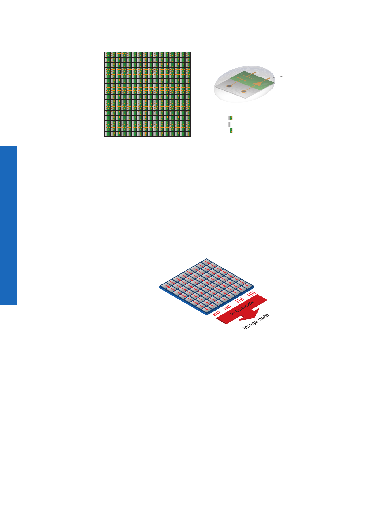
Figure6►
Digitization Tap of the
Baumer LXC cameras
Readout with 16 channel
8.1.3 Digitization Taps
The CMOSIS sensors, employed in Baumer LXC cameras are read out with 16 channels
in parallel.
20
Page 21
8.1.4 Field of View Position
β
β
The typical accuracy by assumption of the root mean square value is displayed in the
gures and the table below:
±
A'
M
±Y
LXC-20, LXC-40
±X
M
A'
R
±Y
±X
A
R
A
±X
M
A'
A'
M
±Y
LXC-120, LXC-200, LXC-250
Camera
Type
A
± x
[mm]
M,typ
R
±X
± y
[mm]
M,typ
R
±Y
± x
[mm]
R,typ
A
± y
[mm]
R,typ
± β
[°]
LXC-20 0.09 0.09 0.1 0.1 0.4
LXC-40 0.09 0.09 0.1 0.1 0.4
LXC-120 0.07 0.06 0.08 0.07 0.26
LXC-200 0.08 0.08 0.09 0.08 0.27
LXC-250 0.07 0.06 0.08 0.07 0.47
◄Figure7
Sensor accuracy of
Baumer LXC cameras.
typ
21
Page 22
8.2 Timings
Exposur
Readout
Exposur
Readout
Exposur
Readout
Flas
Notice
Overlapped mode can be switched off with setting the readout mode to sequential shut-
ter instead of overlapped shutter.
The image acquisition consists of two separate, successively processed components.
Exposing the pixels on the photosensitive surface of the sensor is only the rst part of the
image acquisition. After completion of the rst step, the pixels are read out.
Thereby the exposure time (t
ed for the readout (t
) is given by the particular sensor and image format.
readout
) can be adjusted by the user, however, the time need-
exposure
Baumer cameras can be operated with two modes, the Free Running Mode and the
Trigger Mode.
1)
The cameras can be operated non-overlapped
or overlapped. Depending on the mode
used, and the combination of exposure and readout time:
Non-overlapped Operation Overlapped Operation
Here the time intervals are long enough
to process exposure and readout successively.
e
In this operation the exposure of a frame
(n+1) takes place during the readout of
frame (n).
e
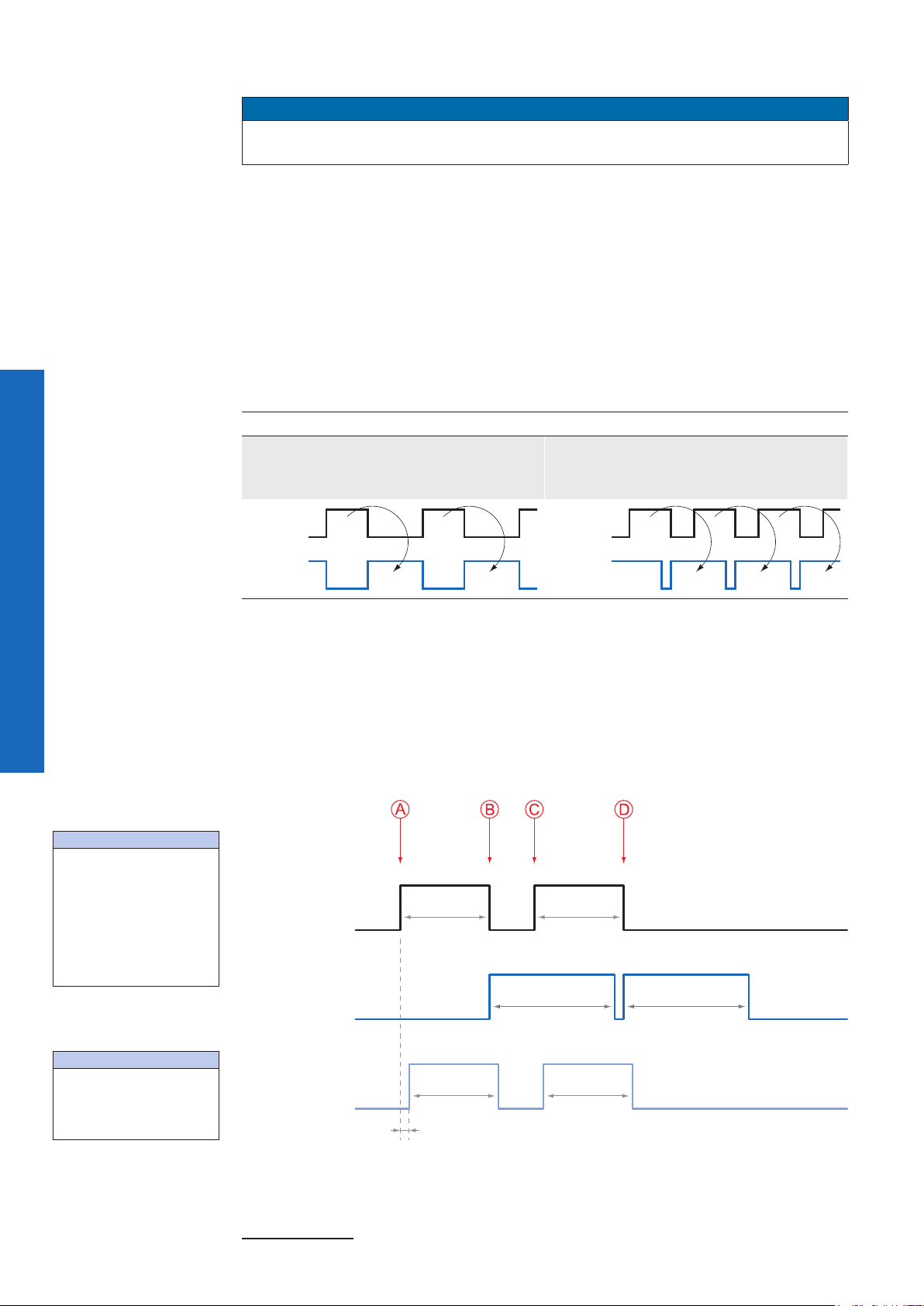
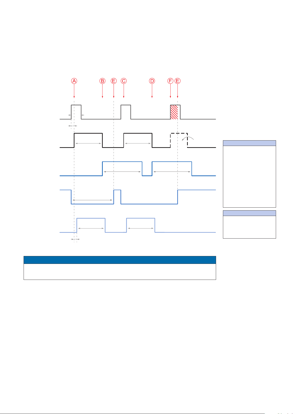
8.2.1 Free Running Mode
In the "Free Running" mode the camera records images permanently and sends them to
the PC. In order to achieve an optimal (with regard to the adjusted exposure time t
and image format) the camera is operated overlapped.
exposure
Timings:
A - exposure time
frame (n) effective
B - image parameters
frame (n) effective
C - exposure time
frame (n+1) effective
D - image parameters
frame (n+1) effective
Image parameters:
Offset
Gain
Mode
Partial Scan
In case of exposure times equal to / less than the readout time (t
exposure
≤ t
), the maxi-
readout
mum frame rate is provided for the image format used. For longer exposure times the
frame rate of the camera is reduced.
t
exposure(n)
t
exposure(n+1)
e
t
readout(n+1)
t
flash(n)
t
readout(n)
t
flash(n+1)
h
t
flashdelay
t
= t
ash
exposure
22
1) Non-overlapped means the same as sequential.
Page 23

8.2.2 Trigger Mode
Exposur
Readout
Tr
Flas
Tr
After a specied external event (trigger) has occurred, image acquisition is started. Depending on the interval of triggers used, the camera operates non-overlapped or overlapped in this mode.
With regard to timings in the trigger mode, the following basic formulas need to be taken
into consideration:
Case Formula
t
exposure
t
exposure
< t
> t
readout
readout
(1) t
(2) t
(3) t
(4) t
earliestpossibletrigger(n+1)
notready(n+1)
earliestpossibletrigger(n+1)
notready(n+1)
= t
exposure(n)
= t
exposure(n)
= t
readout(n)
+ t
= t
exposure(n)
- t
readout(n)
exposure(n+1)
- t
exposure(n+1)
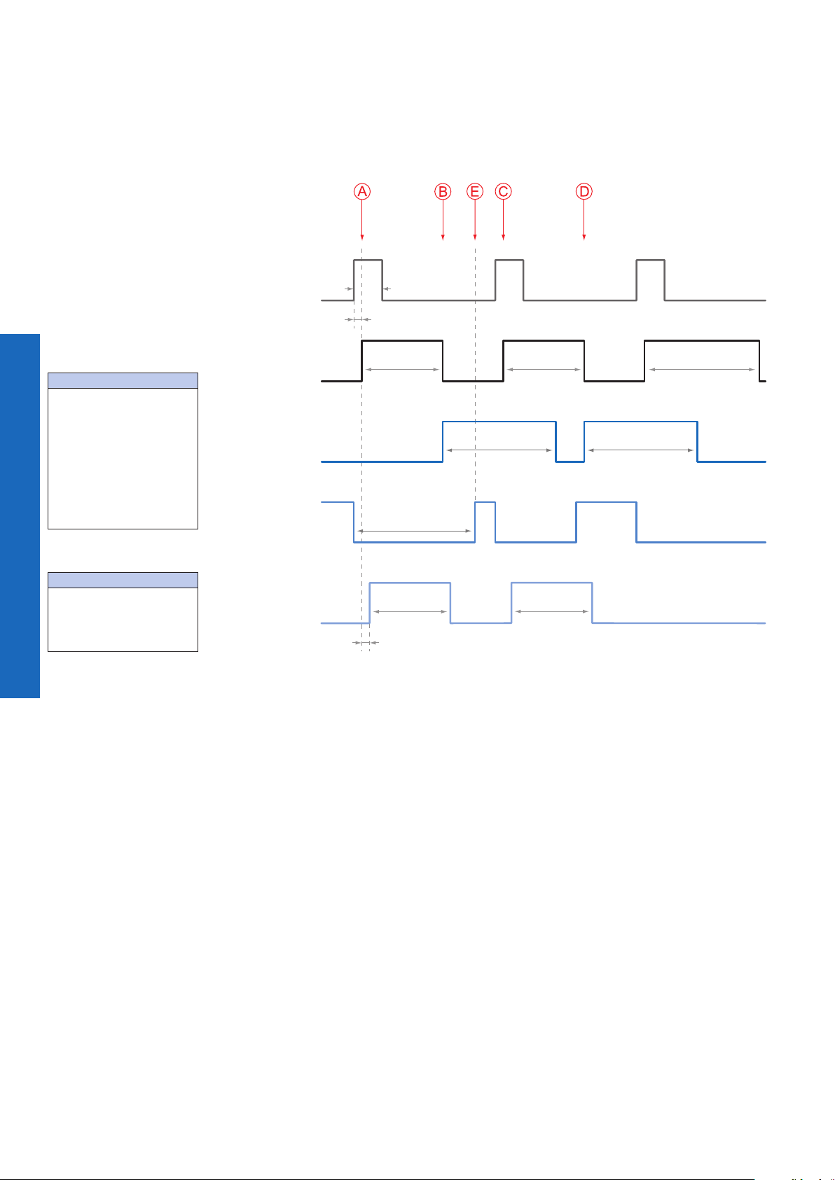
8.2.2.1 Overlapped Operation: t
exposure(n+2)
= t
exposure(n+1)
In overlapped operation attention should be paid to the time interval where the camera is
unable to process occuring trigger signals (t
exposures. When this process time t
notready
). This interval is situated between two
notready
has elapsed, the camera is able to react to
external events again.
After t
age (t
has elapsed, the timing of (E) depends on the readout time of the current im-
notready
) and exposure time of the next image (t
readout(n)
exposure(n+1)
). It can be determined by the
formulas mentioned above (no. 1 or 3, as is the case).
In case of identical exposure times, t
remains the same from acquisition to acquisi-
notready
tion.
t
igger
min
t
triggerdelay
t
exposure(n)
t
exposure(n+1)
e
t
readout(n+1)
t
notready
t
readout(n)
iggerReady
Timings:
A - exposure time
frame (n) effective
B - image parameters
frame (n) effective
C - exposure time
frame (n+1) effective
D - image parameters
frame (n+1) effective
E - earliest possible trigger
Image parameters:
t
flash(n)
t
flash(n+1)
h
t
flashdelay
Offset
Gain
Mode
Partial Scan
23
Page 24
8.2.2.2 Overlapped Operation: t
Flas
exposure(n+2)
> t
exposure(n+1)
Timings:
A - exposure time
frame (n) effective
B - image parameters
frame (n) effective
C - exposure time
frame (n+1) effective
D - image parameters
frame (n+1) effective
E - earliest possible trigger
If the exposure time (t
tion, the time the camera is unable to process occuring trigger signals (t
) is increased from the current acquisition to the next acquisi-
exposure
notready
) is scaled
down.
This can be simulated with the formulas mentioned above (no. 2 or 4, as is the case).
t
Trigger
min
t
triggerdelay
t
exposure(n)
t
exposure(n+1)
t
exposure(n+2)
Exposure
t
readout(n)
t
readout(n+1)
Readout
t
notready
TriggerReady
Image parameters:
Offset
Gain
Mode
Partial Scan
t
flash(n)
t
flash(n+1)
h
t
flashdelay
24
Page 25
8.2.2.3 Overlapped Operation: t
Exposur
Readout
exposure(n+2)
Tr
Flas
Tr
exposure(n+2)
< t
exposure(n+1)
If the exposure time (t
tion, the time the camera is unable to process occuring trigger signals (t
) is decreased from the current acquisition to the next acquisi-
exposure
notready
) is scaled
up.
When decreasing the t
exposure
such, that t
exceeds the pause between two incoming
notready
trigger signals, the camera is unable to process this trigger and the acquisition of the image will not start (the trigger will be skipped).
t
igger
min
t
triggerdelay
t
exposure(n)
t
exposure(n+1)
t
e
t
readout(n+1)
t
notready
t
readout(n)
iggerReady
Timings:
A - exposure time
frame (n) effective
B - image parameters
frame (n) effective
C - exposure time
frame (n+1) effective
D - image parameters
frame (n+1) effective
E - earliest possible trigger
F - frame not started /
trigger skipped
t
flash(n)
t
flash(n+1)
h
t
flashdelay
Notice
From a certain frequency of the trigger signal, skipping triggers is unavoidable. In general, this frequency depends on the combination of exposure and readout times.
Image parameters:
Offset
Gain
Mode
Partial Scan
25
Page 26

8.2.2.4 Non-overlapped Operation
Flas
If the frequency of the trigger signal is selected for long enough, so that the image acquisitions (t
Trigger
exposure
+ t
) run successively, the camera operates non-overlapped.
readout
t
min
t
triggerdelay
Timings:
A - exposure time
frame (n) effective
B - image parameters
frame (n) effective
C - exposure time
frame (n+1) effective
D - image parameters
frame (n+1) effective
E - earliest possible trigger
Image parameters:
Offset
Gain
Mode
Partial Scan
Exposure
Readout
TriggerReady
h
t
exposure(n)
t
notready
t
flash(n)
t
flashdelay
t
readout(n)
t
exposure(n+1)
t
flash(n+1)
t
readout(n+1)
26
Page 27

9. Software
9.1 Frame grabber with GenCP support
The camera can be controlled via the GenCP/GenICam protocol. The SDK of some Camera Link frame grabber vendors directly supports this. Thus, only this SDK is required for
image acquisition and camera conguration. See compliance list for details which frame
grabbers support this.
9.2 Frame grabber without GenCP support
The camera can be controlled via the GenCP/GenICam protocol. If the SDK of the Camera Link frame grabber does not support the GenCP/GenICam protocol, the GenICam
Reference implementation can be used for camera conguration.
Notice
Latest software version and technical documentation are available at:
www.baumer.com/vision/login (registration required)
27
Page 28

10. Camera Functionalities
10.1 Image Acquisition
10.1.1 Image Format
A digital camera usually delivers image data in at least one format - the native resolution
of the sensor. Baumer cameras are able to provide several image formats (depending on
the type of camera).
Compared with standard cameras, the image format on Baumer cameras not only includes resolution, but a set of predened parameter.
These parameters are:
▪ Resolution (horizontal and vertical dimensions in pixels)
▪ Binning Mode
▪ Decimation
Camera Type
Mono
LXC-20M ■ ■ ■ ■ ■ ■ ■
LXC-40M ■ ■ ■ ■ ■ ■ ■
LXC-120M ■ ■ ■ ■ ■ ■ ■
LXC-200M ■ ■ ■ ■ ■ ■ ■
LXC-250M ■ ■ ■ ■ ■ ■ ■
Color
LXC-20C ■ □ □ □ ■ ■ ■
LXC-40C ■ □ □ □ ■ ■ ■
LXC-120C ■ □ □ □ ■ ■ ■
LXC-200C ■ □ □ □ ■ ■ ■
LXC-250C ■ □ □ □ ■ ■ ■
Full frame
Binning 2x2
Binning 1x2
Binning 2x1
Decimation 2x2
Decimation 1x2
Decimation 2x1
28
Page 29

10.1.2 Pixel Format
On Baumer digital cameras the pixel format depends on the selected image format.
10.1.2.1 Pixel Formats on Baumer LXC Cameras
Camera Type
Mono8
Mono10
Mono12
BayerGB8
BayerGB10
Bayer RG8
Bayer RG10
Monochrome
LXC-20M ■ ■ □ □ □ □ □ □
LXC-40M ■ ■ □ □ □ □ □ □
LXC-120M ■ ■ □ □ □ □ □ □
LXC-200M ■ ■ ■ □ □ □ □ □
LXC-250M ■ ■ □ □ □ □ □ □
Color
LXC-20C □ □ □ ■ ■ □ □ □
LXC-40C □ □ □ ■ ■ □ □ □
LXC-120C □ □ □ ■ ■ □ □ □
LXC-200C □ □ □ □ □ ■ ■ ■
LXC-250C □ □ □ ■ ■ □ □ □
10.1.2.2 Denitions
Notice
Below is a general description of pixel formats. The table above shows, which camera
support which formats.
Bayer RG12
Bayer: Raw data format of color sensors.
Color lters are placed on these sensors in a checkerboard pattern, generally
in a 50% green, 25% red and 25% blue array.
Mono: Monochrome. The color range of mono images consists of shades of a single
color. In general, shades of gray or black-and-white are synonyms for monochrome.
◄Figure8
Sensor with Bayer
Pattern.
29
Page 30

RGB: Color model, in which all detectable colors are dened by three coordinates,
Red
Gree
Blue
Byte 1 Byte 2 Byte 3
Byte 1 Byte 2
unused bits
Byte 1 Byte 2
unused bits
Red, Green and Blue.
White
Black
Figure9►
RBG color space displayed as color tube.
n
The three coordinates are displayed within the buffer in the order R, G, B.
BGR: Here the color alignment mirrors RGB.
YUV: Color model, which is used in the PAL TV standard and in image compression.
In YUV, a high bandwidth luminance signal (Y: luma information) is transmitted
together with two color difference signals with low bandwidth (U and V: chroma
information). Thereby U represents the difference between blue and luminance
(U = B - Y), V is the difference between red and luminance (V = R - Y). The third
color, green, does not need to be transmitted, its value can be calculated from
the other three values.
YUV 4:4:4 Here each of the three components has the same sample rate.
Therefore there is no subsampling here.
YUV 4:2:2 The chroma components are sampled at half the sample rate.
This reduces the necessary bandwidth to two-thirds (in relation to
4:4:4) and causes no, or low visual differences.
YUV 4:1:1 Here the chroma components are sampled at a quarter of the
sample rate.This decreases the necessary bandwith by half (in
relation to 4:4:4).
Figure10►
Bit string of Mono 8 bit
and RGB 8 bit.
Figure11►
Spreading of Mono 10
bit over 2 bytes.
Figure12►
Spreading of Mono 12
bit over two bytes.
Pixel depth: In general, pixel depth denes the number of possible different values for
8
each color channel. Mostly this will be 8 bit, which means 2
different "col-
ors".
For RGB or BGR these 8 bits per channel equal 24 bits overall.
8 bit:
10 bit:
12 bit:
30
Page 31

10.1.3 Exposure Time
On exposure of the sensor, the inclination of photons produces a charge separation on
the semiconductors of the pixels. This results in a voltage difference, which is used for
signal extraction.
Light
Photon
Charge Carrier
Pixel
The signal strength is inuenced by the incoming amount of photons. It can be increased
by increasing the exposure time (t
exposure
).
On Baumer LXC cameras, the exposure time can be set within the following ranges (step
size 1μsec):
Camera Type t
min t
exposure
exposure
max
LXC-20M / C 30 μsec 1 sec
LXC-40M / C 30 μsec 1 sec
LXC-120M / C 16 μsec 1 sec
LXC-200M / C 200 μsec 1 sec
LXC-250M / C 27 μsec 1 sec
Notice
The exposure time can be programmed or controlled via trigger width.
However, the sensor needs additional time for the sampling operation during which the
sensor is still light sensitive. As a consequence the real minimum exposure time is the
respective t
exposure
min longer.
◄Figure13
Incidence of light
causes charge separation on the semiconductors of the sensor.
10.1.4 PRNU / DSNU Correction (FPN - Fixed Pattern Noise)
CMOS sensors exhibit nonuniformities that are often called xed pattern noise (FPN).
However it is no noise but a xed variation from pixel to pixel that can be corrected. The
advantage of using this correction is a more homogeneous picture which may simplify the
image analysis. Variations from pixel to pixel of the dark signal are called dark signal nonuniformity (DSNU) whereas photo response nonuniformity (PRNU) describes variations
of the sensitivity. DNSU is corrected via an offset while PRNU is corrected by a factor.
The correction is based on columns. It is important that the correction values are comput-
ed for the used sensor readout conguration. During camera production this is derived for
the factory defaults. If other settings are used (e.g. different number of readout channels)
using this correction with the default data set may degrade the image quality. In this case
the user may derive a specic data set for the used setup.
PRNU / DSNU Correction Off PRNU / DSNU Correction On
31
Page 32
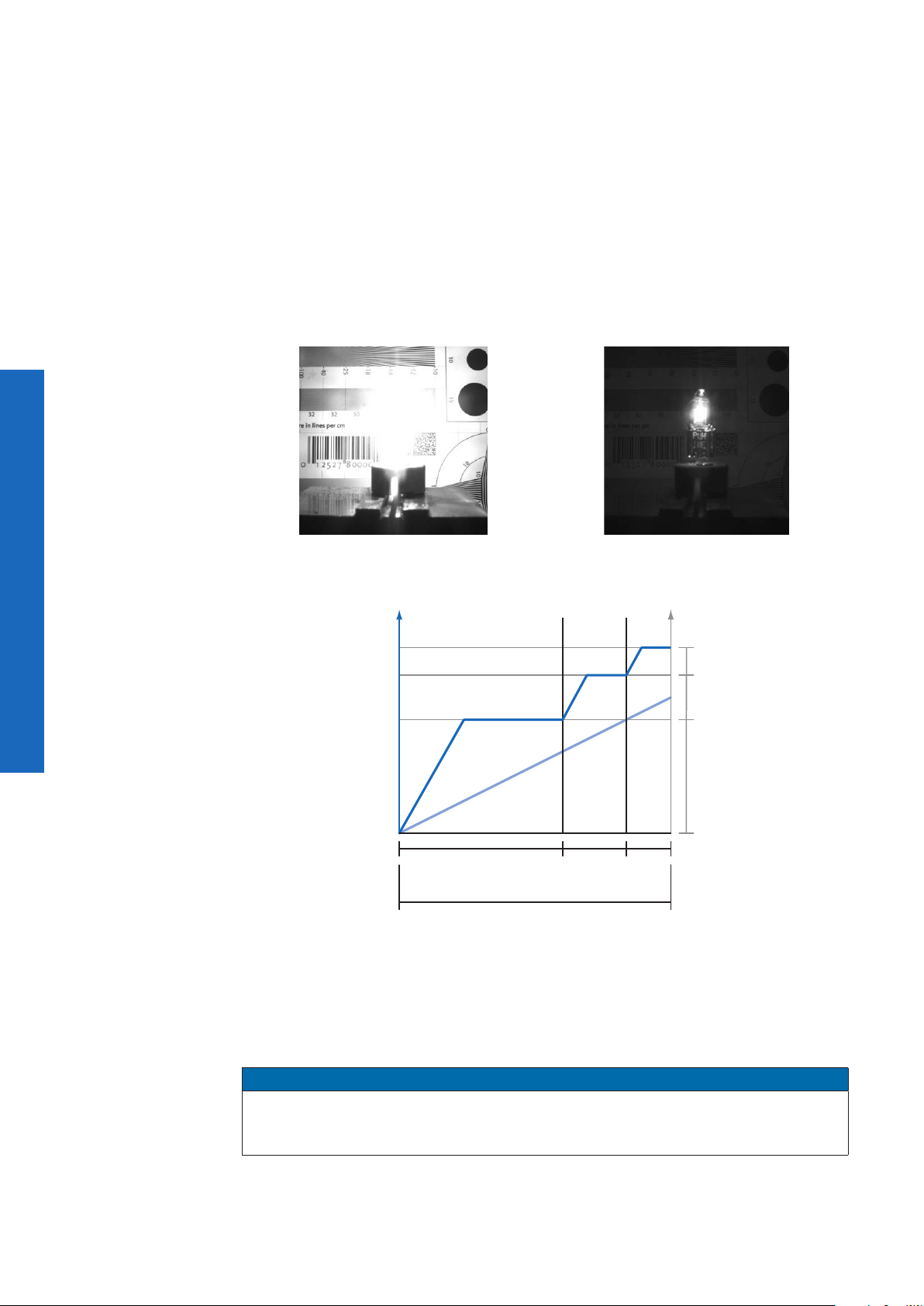
10.1.5 HDR
Beside the standard linear response the sensor supports a special high dynamic range
mode (HDR) called piecewise linear response. With this mode illuminated pixels that
reach a certain programmable voltage level will be clipped. Darker pixels that do not reach
this threshold remain unchanged. The clipping can be adjusted two times within a single
exposure by conguring the respective time slices and clipping voltage levels. See the
gure below for details.
, t
In this mode, the values for t
The value for t
t
)
Expo1
will be calculated automatically in the camera. (t
Expo2
Expo0
, Pot0 and Pot1can be edited.
Expo1
Expo2
= t
exposure
- t
Expo0
-
HDR Off HDR On
Sensor Output
10.1.6 Look-Up-Table
Illumination
High
ow Illumination
L
t
Expo0
t
exposure
t
Expo1tExpo2
Pot
Pot
Pot
2
1
0
32
The Look-Up-Table (LUT) is employed on Baumer monochrome cameras. It contains 212
(4096) values for the available levels of gray. These values can be adjusted by the user.
Notice
The LUT always calculates with 12 bit input and 12 bit output. In 8/10 bit mode, the lower
bits of the input values are equal zero but can be spread to full 12 bit because of digital
gain. Therefore, all values of the LUT have to be lled in.
Page 33
10.1.7 Gamma Correction
Start ROI
H
E0
With this feature, Baumer LXC cameras offer the possibility of compensating nonlinearity
in the perception of light by the human eye.
For this correction, the corrected pixel intensity (Y') is calculated from the original intensity
of the sensor's pixel (Y
) and correction factor γ using the following formula (in over-
original
simplied version):
γ
Y' = Y
original
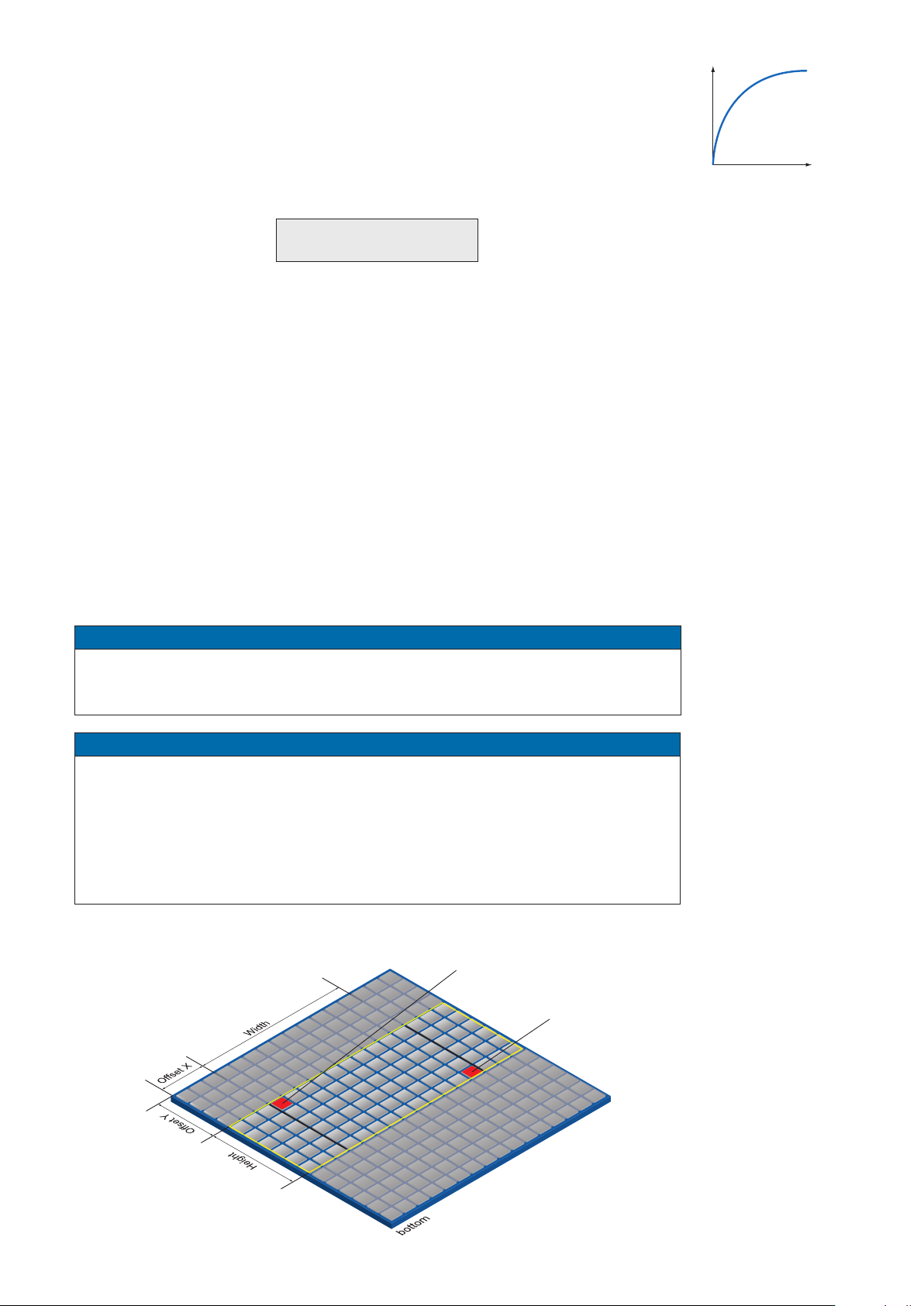
10.1.8 Region of Interest (ROI) and Multi ROI
With this functions it is possible to predene a so-called Region of Interest (ROI) or Partial
Scan. The ROI is an area of pixels of the sensor. After image acquisition, only the information of these pixels is sent to the PC.
This functions is turned on, when only a region of the eld of view is of interest. It is
coupled to a reduction in resolution and increases the frame rate.
The ROI is specied by following values:
▪ Region Selector Region 0 / Multi-ROI horizontal 1-8, Multi-ROI vertical 1-8
▪ Region Mode On/Off
▪ Offset X - x-coordinate of the rst relevant pixel
▪ Offset Y - y-coordinate of the rst relevant pixel
▪ Width - horizontal size of the ROI
▪ Height - vertical size of the ROI
▲Figure14
Non-linear perception of
the human eye.
H - Perception of bright ness
E - Energy of light
Notice
The values of the Offset X and Size X must be a multible of 32!
The step size in Y direction is 1 pixel at monochrome cameras and 2 pixel at color cam-
eras.
Notice
If defect pixels should exist in the rst (mono cameras) or in the rst two (color
cameras) rows or columns of a ROI, these cannot be corrected with the defect
pixel correction. In this case you need to move or increase the ROI by a few
pixels.
The coordinates of defect pixels can be read out with the Camera Explorer
(Category: Control LUT).
End ROI
◄Figure15
Parameters of the ROI.
33
Page 34
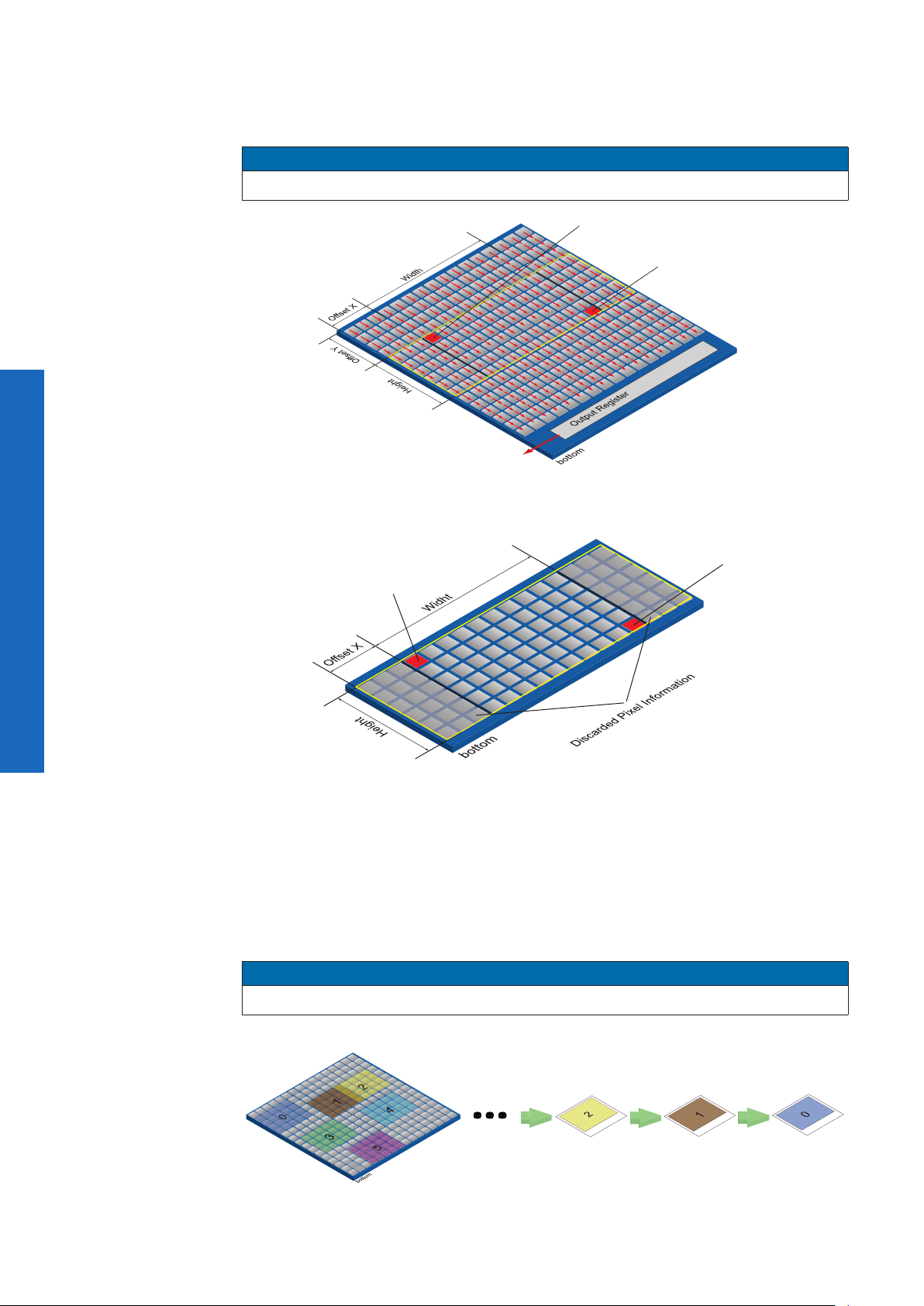
ROI: Readout
10.1.8.1 Normal- ROI Readout (Region 0)
For the sensor readout time of the ROI, the horizontal subdivision of the sensor is unimportant – only the vertical subdivision is of importance.
Notice
The activation of ROI turns off all Multi-ROIs.
Start ROI
End ROI
Figure16►
The readout is line based, which means always a complete line of pixels needs to be read
out and afterwards the irrelevant information is discarded.
Figure17►
ROI:
Discarded Information
End ROI
Start ROI
10.1.9 Multi-ROI
With Multi-ROI it is possible to predene several Region of Interests (ROIs). It can be
specied up to 8 ROIs (Region 0 - Region 7), which must have the same size. Overlapped
ROIs (in the gure Region 1 and Region 2) are possible.
The camera only reads out sensor parts that are within one of the active Multi Regions.
Each dened ROI is sequentially transferred in a separate frame.
The activation of Multi-ROI turns off ROI.
Notice
Multi-ROI can not be used simultaneously with Binning.
Figure18►
Result frames generat-
ed by using Multi-ROI´s
34
Page 35
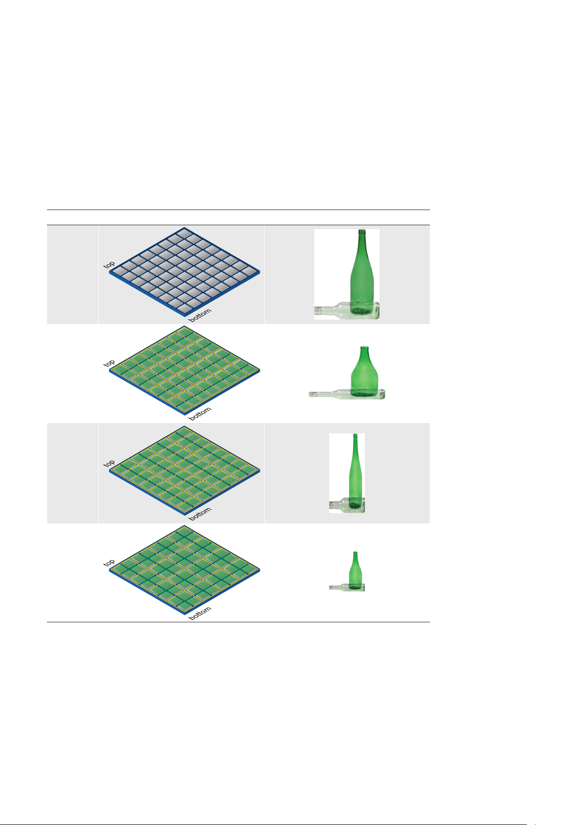
10.1.10 Binning
On digital cameras, you can nd several operations for progressing sensitivity. One of
them is the so-called "Binning". Here, the charge carriers of neighboring pixels are aggregated. Thus, the progression is greatly increased by the amount of binned pixels. By
using this operation, the progression in sensitivity is coupled to a reduction in resolution.
Baumer cameras support three types of Binning – vertical, horizontal and bidirectional.
In unidirectional binning, vertically or horizontally neighboring pixels are aggregated and
reported to the software as one single "superpixel".
In bidirectional binning, a square of neighboring pixels is aggregated.
Binning Illustration Example
without
1x2
2x1
2x2
◄Figure19
Full frame image, no
binning of pixels.
◄Figure20
Vertical binning causes
a vertically compressed
image with doubled
brightness.
◄Figure21
Horizontal binning
causes a horizontally
compressed image with
doubled brightness.
◄Figure22
Bidirectional binning
causes both a horizontally and vertically
compressed image with
quadruple brightness.
35
Page 36
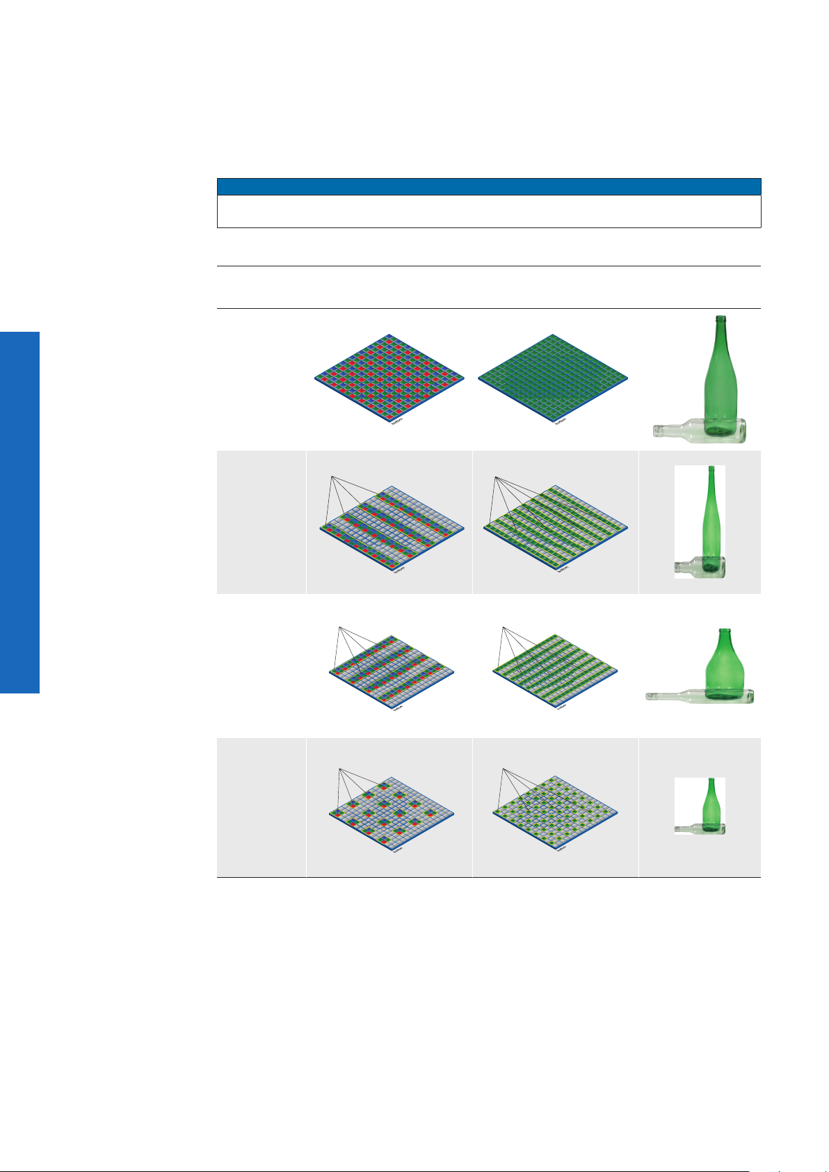
10.1.11 Decimation (sub-sampling)
Readout pixels
Readout pixels
Readout pixels
Readout pixels
Readout pixels
Readout pixels
In this mode, the sensor is read out partially. Thus the frame rate is increased and the
amount of data transferred is reduced.
It is available for mono and color cameras. With color cameras, a color correct readout of
the pixels takes place.
Notice
The camera must be stopped before decimation can be set.
Figure23►
Full frame image, no
decimation of pixels.
Figure24►
Vertical decimation
causes a vertically compressed image.
Figure25►
Horizontal decimation
causes a horizontally
compressed.
Decimation Illustration
color mono
without
1x2
2x1
Example
Figure26►
Bidirectional decimation
causes both a horizontally and vertically compressed image.
36
2x2
Page 37

10.1.12 Brightness Correction (Binning Correction)
non-adjusted
histogramm after
non-adjusted
histogramm after
The summation of pixel values may cause an overload. To prevent this, binning correction
was introduced.
Binninig Realization
1x2 1x2 binning is performed within the sensor, binning correction also takes
place here. A possible overload is prevented by halving the exposure time.
2x1 2x1 binning takes place within the FPGA of the camera. The binning cor-
rection is realized by aggregating the charge quantities, and then halving
this sum.
2x2 2x2 binning is a combination of the above versions.
Total charge
quantity of the
Binning 2x2
Charge quantity
4 aggregated
pixels
Super pixel
10.2 Color Adjustment – White Balance
◄Figure27
Aggregation of charge
carriers from four pixels
in bidirectional binning.
This feature is available on all color Baumer LXC cameras and takes place within
the Bayer processor.
White balance means independent adjustment of the three color channels, red,
green and blue by employing of a correction factor for each channel.
10.2.1 User-specicColor Adjustment
The user-specic color adjustment in Baumer color cameras facilitates adjustment of the
correction factors for each color gain. This way, the user is able to adjust the amplica-
tion of each color channel exactly to his needs. The correction factors for the color gains
range from 1 to 4.
histogramm
user-specific
color adjustment
10.2.2 One Push White Balance
Notice
Due to the internal processing of the camera, One Push White Balance refers to the
current ROI but always considers the entire row.
◄Figure28
Examples of histogramms for a nonadjusted image and for
an image after user-
specic white balance..
Here, the three color spectrums are balanced to a single white point. The correction factors of the color gains are determined by the camera (one time).
histogramm
„one push“ white
balance
◄Figure29
Examples of histogramms for a non-adjusted image and for an
image after "one push"
white balance.
37
Page 38

10.3 Analog Controls
10.3.1 Offset / Black Level
On Baumer LXC cameras the offset (or black level) is adjustable.
Camera Type 1 step = 4 LSB
Relating to [bit]
Monochrome
LXC-20M 0 ... 63 LSB | 10 bit
LXC-40M 0 ... 63 LSB | 10 bit
LXC-120M 0 ... 63 LSB | 10 Bit
LXC-200M 0 ... 255 LSB | 12 Bit
LXC-250M 0 ... 63 LSB | 10 Bit
Color
LXC-20C 0 ... 63 LSB | 10 bit
LXC-40C 0 ... 63 LSB | 10 bit
LXC-120C 0 ... 63 LSB | 10 Bit
LXC-200C 0 ... 255 LSB | 12 Bit
LXC-250C 0 ... 63 LSB | 10 Bit
10.3.2 Gain
In industrial environments motion blur is unacceptable. Due to this fact exposure times
are limited. However, this causes low output signals from the camera and results in dark
images. To solve this issue, the signals can be amplied by user within the camera. This
gain is adjustable from 0 to 12 db.
Notice
Increasing the gain factor causes an increase of image noise and leads to missing
codes at Mono12, if the gain factor > 1.0.
38
Page 39
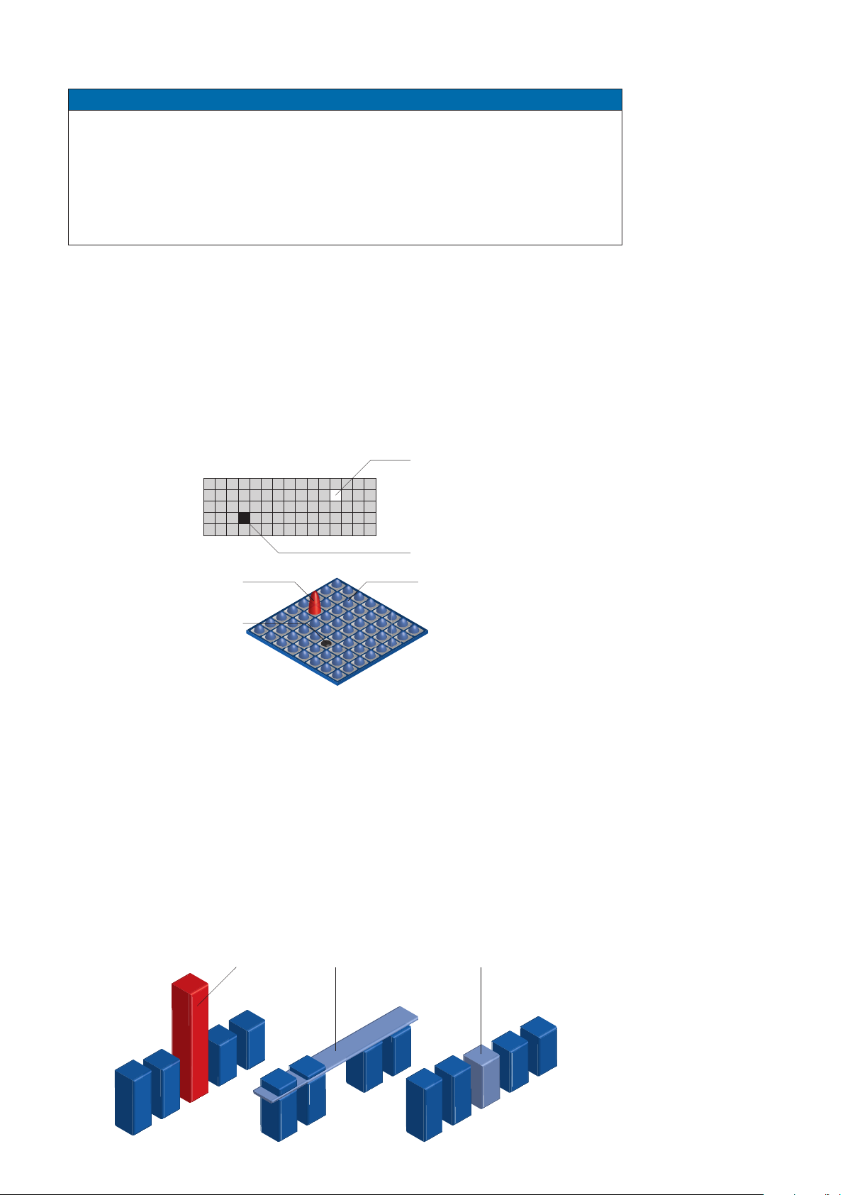
10.4 Pixel Correction
Charge quantity
„Normal Pixel“
Charge quantity
„Cold Pixel“
Charge quantity
„Warm Pixel“
Defect Pixel Average Value Corrected Pixel
Notice
If defect pixels should exist in the rst (mono cameras) or in the rst two (color
cameras) rows or columns of a ROI, these cannot be corrected with the defect
pixel correction. In this case you need to move or increase the ROI by a few
pixels.
The coordinates of defect pixels can be read out with the Camera Explorer
(Category: Control LUT).
10.4.1 General information
A certain probability for abnormal pixels - the so-called defect pixels - applies to the sensors of all manufacturers. The charge quantity on these pixels is not linear-dependent on
the exposure time.
The occurrence of these defect pixels is unavoidable and intrinsic to the manufacturing
and aging process of the sensors.
The operation of the camera is not affected by these pixels. They only appear as brighter
(warm pixel) or darker (cold pixel) spot in the recorded image.
Warm Pixel
Cold Pixel
10.4.2 Correction Algorithm
On Baumer LXC cameras the problem of defect pixels is solved as follows:
▪ Possible defect pixels are identied during the production process of the camera.
▪ The coordinates of these pixels are stored in the factory settings of the camera.
Once the sensor readout is completed, correction takes place:
▪ Before any other processing, the values of the neighboring pixels with the same
color on the left and the right side of the defect pixel, will be read out
▪ Then the average value of these pixels is determined
▪ Finally, the value of the defect pixel is substituted by the previously determined
average value
This works horizontally and vertically. With this approach whole defect rows and defect
columns can be corrected.
◄Figure30
Distinction of "hot" and
"cold" pixels within the
recorded image.
◄Figure31
Charge quantity of "hot" and
"cold" pixels compared with
"normal" pixels.
◄Figure32
Schematic diagram of
the Baumer pixel
correction.
39
Page 40

10.4.3 Add Defect Pixel / Defect Columns / Defect Rows to Defect pixel list
As stated previously, this list is determined within the production process of Baumer cameras and stored in the factory settings. This list is editable.
Additional hot pixels, cold pixels, defect columns or defect rows can develop during the
lifecycle of a camera. In this case Baumer offers the possibility of adding their coordinates
to the defect pixel list.
1)
The user can determine the coordinates
add them to the list. Once the defect pixel list is stored in a user set, pixel correction is
executed for all coordinates on the defect pixel list.
Notice
There are defect pixels, defect columns or defect rows, which occur only under certain
environmental parameters. These include temperatures or exposure settings.
Complete defect pixels, defect columns or defect rows that occur in your application.
Procedure
of the affected pixels, columns and rows and
1.
Start the Camera Camera Link
®
CongTool v2. Connect to the camera. Select
the prole GenICam Expert.
2. Open the category LUT Control.
3. Select the to be corrected defect at Defect Pixel List Selector (Pixel, Column,
Row).
4. Locate an empty Defect Pixel List Index.
An empty Defect Pixel List Index can be recognized by the fact that no entries
are present at Defect Pixel List Entry PosX and Defect Pixel List Entry PosY.
Avoid using existing entries!
5. Determine the coordinates of the defect pixels, defect column or defect row.
Keep the mouse pointer over the defect. The coordinates are displayed in the
status bar.
For simplication, you can enlarge the image.
6.
Enter the determined values of the defect.
Pixel
Enter the determined coordinates for X (Defect Pixel List Entry PosX).
Enter the determined coordinates for Y (Defect Pixel List Entry PosY).
40
Column
Enter the determined column (Defect Pixel List Entry PosX).
Row
Enter the determined row (Defect Pixel List Entry PosY).
7. Activate the registered Defect Pixel List Index (Defect Pixel List Entry Active =
True).
8. Stop the camera and start them again to take over the updated entries.
1) Position in relation to Full Frame Format (Raw Data Format / No ipping).
Page 41
10.5 Sequencer
ABC
10.5.1 General Information
A sequencer is used for the automated control of series of images using different sets of
parameters.
n
A
n
m
A
B
B
n
C
n
x-1
C
o
z
The gure above displays the fundamental structure of the sequencer module.
The loop counter (m) represents the number of sequence repetitions.
The repeat counter (n) is used to control the amount of images taken with the respective
sets of parameters. For each set there is a separate n.
The start of the sequencer can be realized directly (free running) or via an external event
(trigger). The source of the external event (trigger source) must be determined before.
The additional frame counter (z) is used to create a half-automated sequencer. It is absolutely independent from the other three counters, and used to determine the number of
frames per external trigger event.
◄Figure33
Flow chart of
sequencer.
m - number of loop
passes
n - number of set
repetitions
o - number of
sets of parameters
z - number of frames
per trigger
Sequencer Parameter:
The mentioned sets of
parameter include the
following:
▪ Exposure time
▪ Gain factor
▪ Output line value
▪ Origin of ROI (Offset X, Y
)
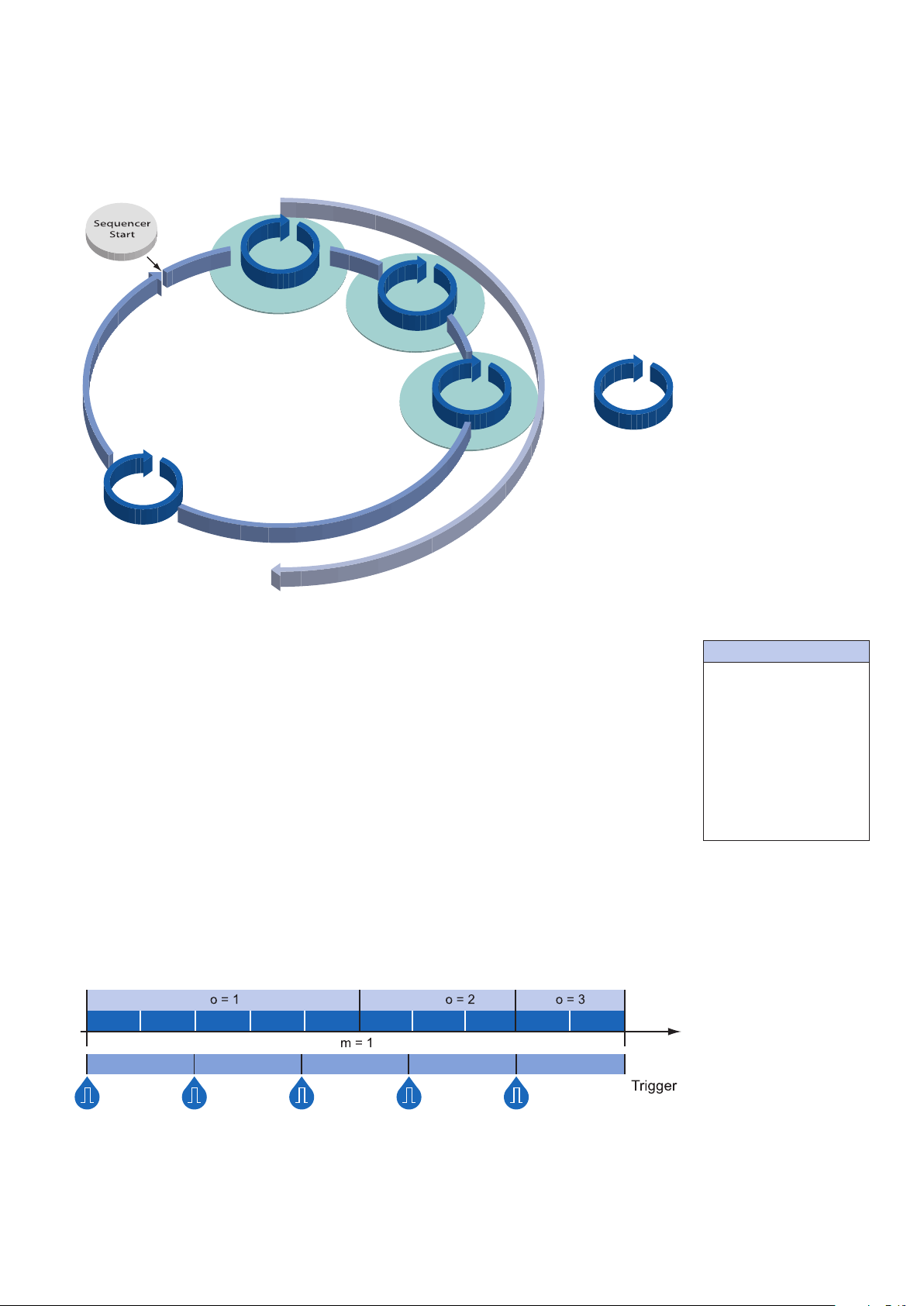
The following timeline displays the temporal course of a sequence with:
▪ n = (A=5), (B=3), (C=2) repetitions per set of parameters
▪ o = 3 sets of parameters (A,B and C)
▪ m = 1 sequence and
▪ z = 2 frames per trigger
n = 1
n = 2
n = 3
n = 4
n = 5
n = 1
n = 2
n = 3
n = 1n = 2
z = 2z = 2z = 2z = 2z = 2
t
◄Figure34
Timeline for a single
sequence
41
Page 42

10.5.2 Baumer Optronic Sequencer in Camera xml-le
The Baumer Optronic seqencer is described in the category
ing features:
Static Sequencer Features
These values are valid for all sets.
BoSequencerEnable
BoSequencerFramesPerTrigger
BoSequencerIsRunning
BoSequencerLoops
BoSequencerMode
BoSequencerSetNumberOfSets
BoSequencerStart
BoSequencerSetActive
Enable / Disable
Number of frames per trigger (z)
Check whether the sequencer is running
Number of sequences (m)
Running mode of Sequencer
Number of sets - 1
Start / Stop
Returns the index of the active set of the
running sequencer.
Set-specicFeatures
These values can be set individually for each set.
BoSequencerExposure
BoSequencerGain
BoSequencerOffsetX
BoSequencerOffsetY
BoSequencerIOSelector
BoSequencerIOStatus
BoSequencerSetRepeats
BoSequencerSetSelector
Parameter exposure
Parameter gain
ROI Offset X
ROI Offset Y
Selected output lines
Status of all Sequencer outputs
Number of repetitions (n)
Congure set of parameters
“BOSequencer”
by the follow-
Figure35►
Example for a fully automated sequencer.
10.5.3 Examples
10.5.3.1 Sequencer without Machine Cycle
C
C
Sequencer
Start
B
B
A
A
The gure above shows an example for a fully automated sequencer with three sets of
parameters (A, B and C). Here the repeat counter (n) is set for (A=5), (B=3), (C=2) and
the loop counter (m) has a value of 2.
42
When the sequencer is started, with or without an external event, the camera will record
the pictures using the sets of parameters A, B and C (which constitutes a sequence).
After that, the sequence is started once again, followed by a stop of the sequencer - in this
case the parameters are maintained.
Page 43

10.5.3.2 Sequencer Controlled by Machine Steps (trigger)
C
C
Sequencer
B
B
Start
A
A
Trigger
The gure above shows an example for a half-automated sequencer with three sets of
parameters (A,B and C) from the previous example. The frame counter (z) is set to 2. This
means the camera records two pictures after an incoming trigger signal.
10.5.4 Capability Characteristics of Baumer GAPI Sequencer Module
◄Figure36
Example for a half-auto-
mated sequencer.
▪ up to 128 sets of parameters
▪ up to 2 billion loop passes
▪ up to 2 billion repetitions of sets of parameters
▪ up to 2 billion images per trigger event
▪ free running mode without initial trigger
43
Page 44

10.5.5 Double Shutter
Tr
Prevent Light
Exposur
Readout
Flas
This feature offers the possibility of capturing two images in a very short interval. Depend-
ing on the application, this is performed in conjunction with a ash unit. Thereby the rst
exposure time (t
sure time must be equal to, or longer than the readout time (t
pixels of the sensor are recepitve again shortly after the rst exposure. In order to realize
the second short exposure time without an overrun of the sensor, a second short ash
must be employed, and any subsequent extraneous light prevented.
) is arbitrary and accompanied by the rst ash. The second expo-
exposure
) of the sensor. Thus the
readout
igger
h
e
Figure37►
Example of a double
shutter.
On Baumer LXC cameras this feature is realized within the sequencer.
In order to generate this sequence, the sequencer must be congured as follows:
Parameter Setting:
Sequencer Run Mode Once by Trigger
Sets of parameters (o) 2
Loops (m) 1
Repeats (n) 1
Frames Per Trigger (z) 2
44
Page 45

10.6 Process Interface
CC
IO GND
CC
IO GND
state selection
10.6.1 Digital I/O
All Baumer LXC cameras are equipped with one input line and one output lines.
10.6.1.1 I/O Circuits
Output high active Output low active Input
Camera Customer Device
U
Pin (Out1, 2, 3)
ext
I
OUT
Out1 or Out2
or Out3
IO Power V
R
L
Out
IO GND
DRV
IN1 Pin
IN_GND Pin
Camera Customer Device
IO Power V
U
Pin
ext
I
OUT
Out (n)
Pin
R
L
10.6.1.2 UserDenableInputs
The wiring of the input connector is left to the user.
CameraCustomer Device
Sole exception is the compliance with predetermined high and low levels (0 .. 4,5V low,
11 .. 30V high).
The dened signals will have no direct effect, but can be analyzed and processed on the
software side and used for controlling the camera.
The employment of a so called "IO matrix" offers the possibility of selecting the signal and
the state to be processed.
On the software side the input signals are named "Line0".
(software side)
state high
(Input) Line0
state low
IO Matrix
Line0
◄Figure38
IO matrix of the
Baumer LXC on input
side.
45
Page 46

10.6.1.3 CongurableOutputs
With this feature, Baumer offers the possibility of wiring the output connectors to internal
signals, which are controlled on the software side.
Hereby on Baumer LXC cameras 17 signal sources – subdivided into three categories –
can be applied to the output connectors.
The rst category of output signals represents a loop through of signals on the input side,
such as:
Signal Name Explanation
Line0 Signal of input "Line0" is loopthroughed to this ouput
Within the second category you will nd signals that are created on camera side:
Signal Name Explanation
FrameActive The camera processes a Frame consisting of exposure
and readout
TriggerReady Camera is able to process an incoming trigger signal
TriggerOverlapped The camera operates in overlapped mode
TriggerSkipped Camera rejected an incoming trigger signal
ExposureActive Sensor exposure in progress
ReadoutActive Read out in progress
Figure39►
IO matrix of the
Baumer LXC on output
side.
Beside the signals mentioned above, each output can be wired to a user-dened signal
("UserOutput1", "SequencerOut 0" or disabled ("OFF").
O
Line0
state selection
(software side)
state high
(Output) Line 0
state low
IO Matrix
signal selection
(software side)
FrameActive
ExposureActive
ReadoutActive
TriggerReady
TriggerSkipped
TriggerOverlapped
UserOutput1
Timer1Active
Timer2Active
Timer3Active
SequencerOutput0
Loopthroughed
Internal Signals
User defined
Signals
Signals
46
Page 47

10.7 Trigger Input / Trigger Delay
t0
Trigger signals are used to synchronize the camera exposure and a machine cycle or, in
case of a software trigger, to take images at predened time intervals.
Different trigger sources can be used here:
Off Line0
All CC 1
Software
Possible settings of the Trigger Delay: :
Delay: 0-2 sec
Number of tracked Triggers: 512
Step: 1 µsec
There are three types of modes. The timing diagrams for the three types you can see
below.
Normal Trigger with adjusted Exposure
U
30V
11V
4.5V
Figure40▲
Trigger signal, valid for
Baumer cameras.
high
low
A
B
Pulse Width controlled Exposure
B
Trigger (valid)
Exposure
Readout
C
Time
Trigger (valid)
Exposure
Camera in trigger
mode:
A - Trigger delay
B - Exposure time
C - Readout time
Readout
C
Time
47
Page 48

10.7.1 Trigger Source
t
r
c
i
c
e
l
s
e
o
t
o
h
p
r
a
w
t
f
o
s
e
n
s
o
r
e
t
r
i
g
g
e
r
l
o
e
l
g
b
i
a
m
m
a
r
g
o
r
p
c
c
o
n
t
r
o
l
l
e
r
e
g
r
g
i
r
t
e
r
a
w
d
r
a
H
s
r
i
g
e
n
g
g
i
r
t
a
l
e
h
r
t
s
o
Figure41►
Examples of possible
trigger sources.
Each trigger source has to be activated separately. When the trigger mode is activated,
the hardware trigger is activated by default.
48
Page 49

10.7.2 Debouncer
Incoming signals
(valid and invalid)
Debouncer
Filtered signal
The basic idea behind this feature was to seperate interfering signals (short peaks) from
valid square wave signals, which can be important in industrial environments. Debouncing
means that invalid signals are ltered out, and signals lasting longer than a user-dened
testing time t
DebounceHigh
In order to detect the end of a valid signal and lter out possible jitters within the signal, a
second testing time t
If the signal value falls to state low and does not rise within t
as end of the signal.
will be recognized, and routed to the camera to induce a trigger.
DebounceLow
was introduced. This timing is also adjustable by the user.
DebounceLow
, this is recognized
The debouncing times t
DebounceHigh
of 1 μsec.
This feature is disabled by default.
U
30V
11V
4.5V
∆t
1
U
30V
11V
and t
∆t
DebounceLow
2
are adjustable from 0 to 5 msec in steps
high
low
∆t
6
5
high
t
DebounceHigh
∆t
∆t4∆t
3
t
DebounceLow
Debouncer:
Please note that the edges
of valid trigger signals are
shifted by t
t
DebounceLow
!
Depending on these
two timings, the trigger
signal might be temporally
stretched or compressed.
t0
t
DebounceHigh
and
10.7.3 Flash Signal
On Baumer cameras, this feature is realized by the internal signal "ExposureActive",
which can be wired to one of the digital outputs.
4.5V
∆tx - high time of the signal
t
DebounceHigh
t
DebounceLow
- user-defined debouncer delay for state high
- user-defined debouncer delay for state low
low
t0
◄Figure42
Principle of the Baumer
debouncer.
49
Page 50

10.7.4 Timer
Timers were introduced for advanced control of internal camera signals.
On Baumer LXC cameras the timer conguration includes four components:
Setting Description
TimeSelector There are three timers. Own settings for each timer can be
made . (Timer1, Timer2, Timer3)
TimerTriggerSource This feature provides a source selection for each timer.
TimerTriggerActivation This feature selects that part of the trigger signal (edges or
states) that activates the timer.
TimerDelay This feature represents the interval between incoming trig-
ger signal and the start of the timer.
(0 μsec .. 2 sec, step: 1 μsec)
TimerDuration By this feature the activation time of the timer is adjustable.
(10 μsec .. 2 sec, step: 1 μsec)
Different Timer sources can be used:
Off Exposure Start
CC 1 Trigger Skipped
Software Frame End
Line 0 Exposure End
Frame Start
For example the using of a timer allows you to control the ash signal in that way, that the
illumination does not start synchronized to the sensor exposure but a predened interval
earlier.
For this example you must set the following conditions:
Setting Value
TriggerSource Line0
TimerTriggerSource Line0
Outputline1 (Source) Timer1Active
TimerTriggerActivation Falling Edge
Trigger Polarity Falling Edge
InputLine0
Exposure
t
triggerdelay
t
TimerDelay
t
exposure
50
t
Timer
TimerDuration
Page 51

10.8 User Sets
Three user sets (1-3) are available for the Baumer LXC cameras. The user sets can contain the following information:
Parameter
ChunkModeActive AcquisitionFrameRate
ChunkEnable PixelFormat
DeviceTapGeometry BlackLevel
DeviceClockFrequency Gain
LUTValue Gamma
LUTEnable TestPattern
HDREnable ReverseX
BlackReferenceCorrectionEnable ReverseY
FixedPatternNoiseCorrection DecimationX
SensorEffectCorrection DecimationY
ReadoutMode LineMode
BoSequencerEnable LineStatus
DefectPixelCorrection LineInverter
ExposureTime LineSource
BinningHorizontal TimerDuration
BinningVertical TimerDelay
TriggerMode TimerTriggerSource
TriggerWidth TimerTriggerActivation
TriggerSource Events
TriggerDelay MultiROI
AcquisitionFrameRateEnable
These user sets are stored within the camera and and cannot be saved outside the device.
By employing a so-called "user set default selector", one of the three possible user sets
can be selected as default, which means, the camera starts up with these adjusted parameters.
10.9 Factory Settings
The factory settings are stored in an additional parametrization set which is used by default. This settings are not editable.
51
Page 52
11. Camera Link® Interface
The Camera Link® interface was specically developed for cameras in machine vision ap-
plications and provides high transfer rates and low latency. Depending on the conguration (Base, Medium or Full) the transfer rate adds up to 850 MBytes/sec.
®
Cameras of the Baumer LXC series are equipped with a Camera Link
therewith able to transmit up to 850 MBytes/sec.
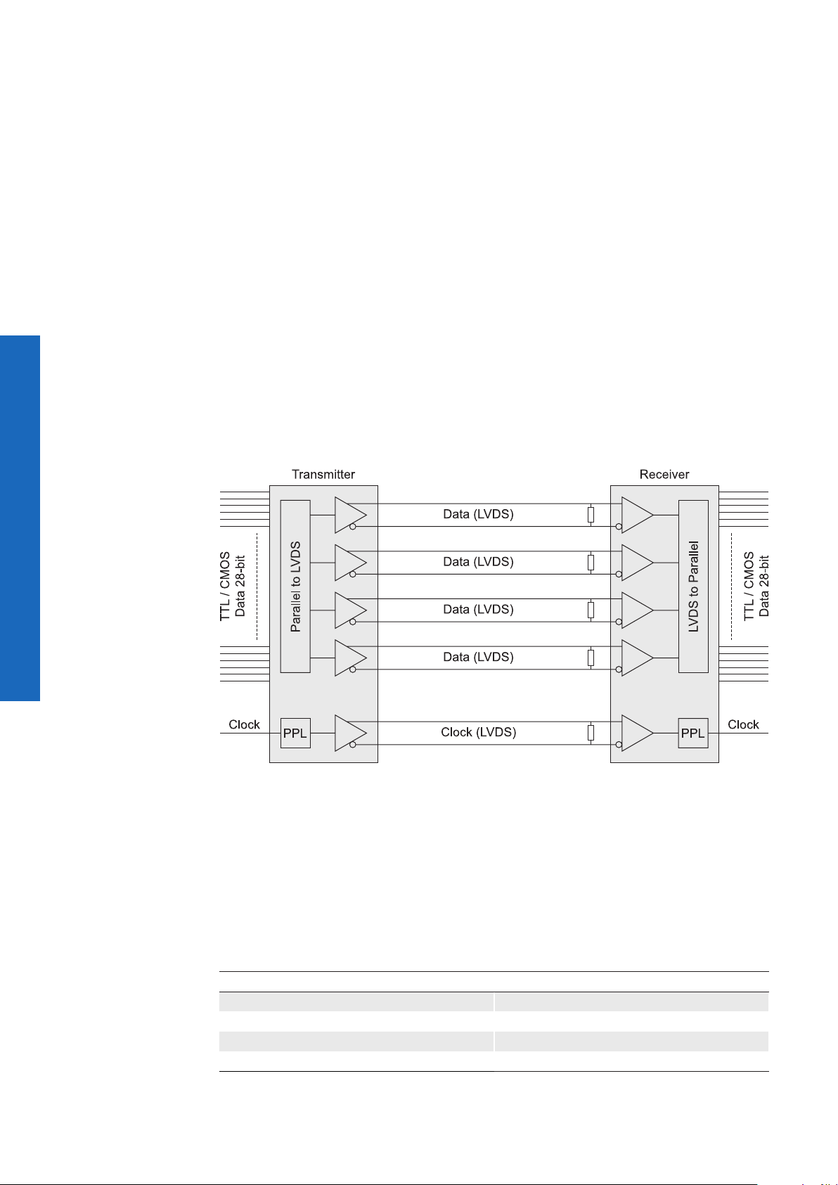
11.1 Channel Link and LVDS Technology
Camera Link® bases upon the Channel Link® technology, but provides a specication, that
is more benecial for machine vision.
®
Channel Link
standard – a low power, high speed interface standard.
The Channel Link
single-ended data signals and a single-ended clock signal can be wired on transmitter
side. Within the transmitter the data is serialized with a ratio of 7:1. Afterwards the four resulting data streams and the clock signal are transferred via ve LVDS pairs. On receiver
side the four LVDS data streams and the LVDS clock are reordered to parallel signals and
afterwards forwarded to further processing.
in turn is an advancement of the LDVS (Low Voltage Differential Signaling)
®
technology consists of a transmitter receiver pair with 21, 28 or 48
Full interface and
Channel Link
tion.
Figure43►
®
opera-
11.2 Camera Signals
The standard designates three different signal types, provided via standard Camera Link®
cable:
11.2.1 Serial Communication
The standard regulates two LVDS pairs are allocated for asynchronous serial communication between the camera and the frame grabber. Cameras and frame grabbers should
support at least 9600 baud serial communication.
Supported baud rates
9600 115200
19200 230400
38400 460800
57600 921600
52
Page 53

The following signals are designated:
Signal Description
SerTFG LVDS pair for serial communications to the frame grabber
SerTC LVDS pair for serial communications to the camera
The serial interface must apply the following regulations:
▪ one start bit,
▪ one stop bit,
▪ no parity and
▪ no handshaking.
11.2.2 Camera Control
According to the Camera Link® standard four LVDS pairs have to be reserved for general-
purpose camera control. They are dened as frame grabber outputs and camera inputs.
The denition of these signals is left to the camera manufacturer.
Signal Baumer Naming Employment
Camera Control 1 (CC1) CC1
Camera Control 2 (CC2) unused
Camera Control 3 (CC3) unused
Camera Control 4 (CC4) unused
On Baumer LXC cameras, the wiring
of these signals is arbitrary.
11.2.3 Video Data
The standard designates three signals (as well as the signal state) for the validation of
transmitted image data:
Signal Description
FVAL Frame Valid is dened high for valid lines.
LVAL Line Valid is dened high for valid pixels.
DVAL Data Valid is dened high for valid data.
53
Page 54

Signal Timing
L
L
L
FVA
LVA
A
F
C
B
D
E
LVA
DVAL
G
H
Description Value
A The time of FVAL High depends on line numbers
B The time from the rising edge of FVAL to the
0
rising edge of LVAL
C The time of LVAL High depends on the CL TAP
Format and pixel per line
D The time of LVAL Low 4 * clock cycle
E The time from the falling edge of LVAL to the
0
falling edge of FVAL
F The time of FVAL Low 64 * clock cycle
G The time from the rising edge of LVAL to the
0
rising edge of DVAL
H The time of DVAL High DVAL = LVAL
Notice
Depending on the used frame grabber, the frame may icker if the values for the camera
features CLLVALLowTime (D) and CLFVALLowTime (F) are set at an unfavorable level.
Increase the values.
The change can cause a slight reduction in the frame rate. Ask the manufacturer of the
frame grabber for the optimal values.
54
Page 55
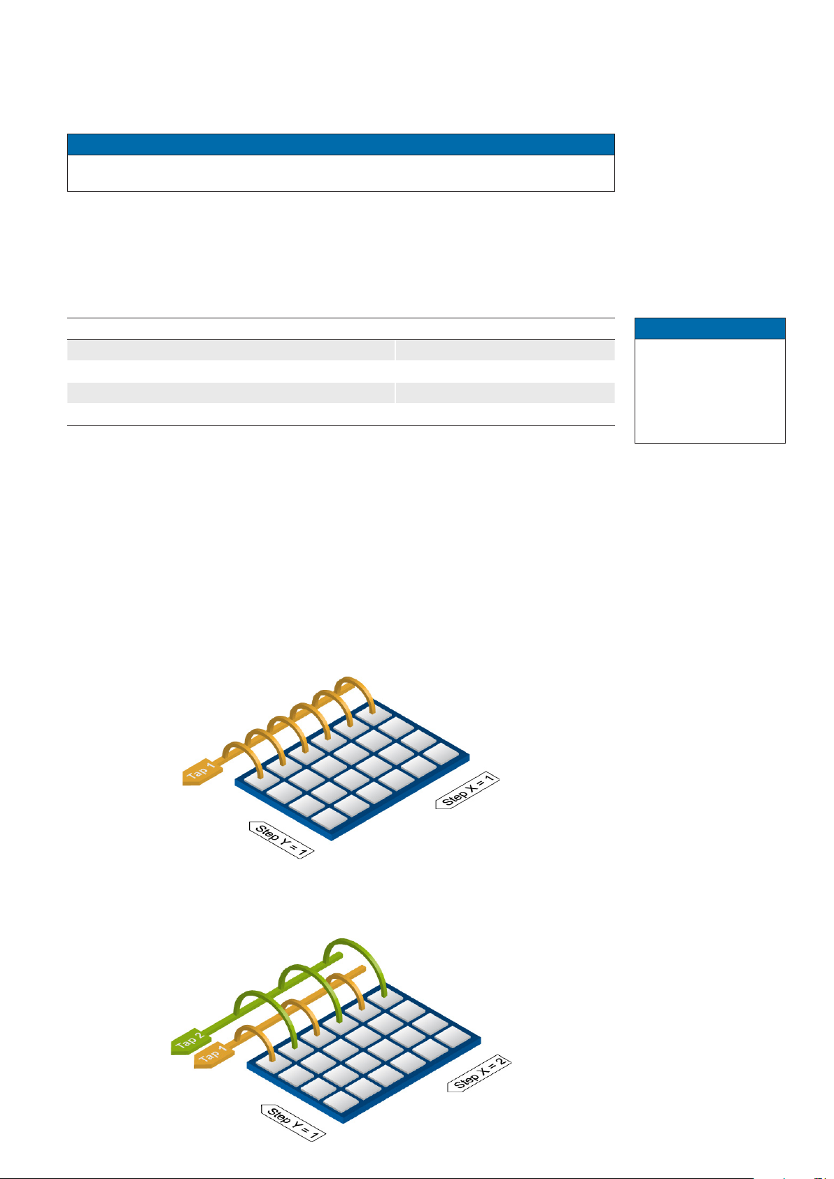
11.3 Camera Link® Taps
The standard denes a tap as "the data path carrying a stream of pixels". This means the
number of taps equates to the number of simultaneously transferred pixel.
Notice
Please do not mix up sensor digitization taps and Camera Link® taps!
11.3.1 TapConguration
Within the subsequent sections, the transmission of images with different pixel formats
(bit depth) linked to the employment of different numbers of taps is displayed.
The following table shows the adjustable tap congurations.
Conguration Cables
CL Base (1T8, 2T8, 3T8, 1T10, 2T10, 1T12, 2T12) 1
CL Medium (3T10, 3T12, 4T8, 4T10 4T12) 2
CL Full (8T8) 2
CL Eighty Bit (10T8, 8T10)
2
11.3.2 Tap Geometry
Since frame grabbers possess the ability of image reconstruction from multi-tap cameras
"on-the-y", the Camera Link® standards demands the specication of the used / supported tap geometries from the manufacturers of both, cameras and frame grabbers.
11.3.2.1 Single Tap Geometry
For single tap transmission the cameras of the Baumer LXC series employ the 1X-1Y tap
geometry:
Notice
nTx
n = number of pixels
x = bit depth
(e.g. 1T8=1 pixel, 8
bit)
11.3.2.2 Dual Tap Geometry
For dual tap transmission the cameras of the Baumer LXC series employ the 1X2-1Y tap
geometry:
◄Figure44
Tap geometry 1X-1Y.
The pixel information
is transmitted pixel-bypixel and line-by-line.
◄Figure45
Tap geometry 1X2-1Y.
55
Page 56

Figure46►
Tap geometry 1X3-1Y.
11.3.2.3 Triple Tap Geometry
For triple tap transmission the cameras of the Baumer LXC series employ the 1X3-1Y tap
geometry:
11.3.2.4 Quad, Eight and Ten Tap Geometry
For Quad, Eight and Ten tap transmission the cameras of the Baumer LXC series use the
same system.
Figure47►
Tap geometry 1X4...101 Y.
56
Page 57

11.4 Chunk Data
The chunk provides additional information about the respective image (e.g. the time-
stamp). When using Baumer LXC cameras, this information is encoded into the last eight
pixels of the image.
This additional information can include:
Information Description
CRC32 Delivers a checksum which ensures that the image is transmitted
correctly.
RegionID Delivers the ID of the Region (Multi-ROI)from which the image
originates.
FrameID Delivers a unique ID for the image in the form of a number.
Timestamp Delivers a timestamp for each image.
Beginning of image
(pImageStart)
The chunk data is assigned to the last 8 pixels as follows, depending on the settings:
Pixel
n-7
Combination
1 Bit 0
2 Bit 0
3 Bit 0
4 Bit 0
5 Bit 0
6 Bit 0
7 Bit 0
Pixel
n-6
CRC32
CRC32
FrameID
RegionID
FrameID
CRC32
Pixel
n-5
Pixel
n-4
Timestamp
Bit 31 Bit 0
Bit 31 Bit 0
Bit 31 Bit 0
Bit 31 Bit 0
Bit 31 Bit 0
Bit 31 Bit 0
Pixel
n-3
Pixel
n-2
RegionID
FrameID
RegionID
Pixel
n-1
0
0
0
Pixel
n
Bit 63
Bit 31
Bit 31
Bit 31
Bit 31
Bit 31
Bit 31
Notice
The programming of the chunk request is described in the document:
AN201517_Baumer_Application_Note_Chunk_LXC_EN.pdf
Latest software version and technical documentation are available at:
www.baumer.com/vision/login (Registration required.)
57
Page 58

12. Cleaning
Avoid cleaning if possible. To prevent dust, follow the instructions under Installation.
Notice
Perform the cleaning in a dust-free room with clean tools. Use localized ionized air ow
on to the glass during cleaning.
12.1 Sensor
Recommended Equipment
▪ Microscope
▪ Air gun
▪ Single drop bottle with pure alcohol
▪ Swab
▪ Phillips screwdriver
Procedure
1. Make sure that the contamination is not on the sensor glass (except LXC-20M,
LXC-40M) or the installed lens.
2. Uninstall the lens mount adapter (except LXC-20M, LXC-40M). Uninstall the
sensor glass (except LXC-20M, LXC-40M) using the phillips screw driver.
3. Blow away mobile contamination using the air gun.
Place the sensor under the microscope to determine the location of any
4.
remaining contamination.
5. Clean the contamination on the sensor using one drop pure alcohol on a swab.
Wipe the swab from left to right (or conversely, but only in one direction). Do this
in an overlapping pattern, turning the swab after the rst wipe and with each
subsequent wipe. Avoid swiping back and forth with the same swab in order to
ensure that particles are removed and not transferred to a new location on the
sensor. Use several swabs for this procedure.
12.2 Cover glass
If you must clean it, use compressed air or a soft, lint free cloth dampened with a small
quantity of pure alcohol.
12.3 Housing
Caution!
58
Volatile solvents for cleaning.
volatile
solvents
To clean the surface of the camera housing, use a soft, dry cloth. To remove persistent
stains, use a soft cloth dampened with a small quantity of neutral detergent, then wipe dry.
Volatile solvents damage the surface of the camera.
Never use volatile solvents (benzine, thinner) for cleaning!
Page 59

13. Transport / Storage
Notice
Transport the camera only in the original packaging. When the camera is not installed,
then storage the camera in the original packaging.
Storage Environment
Storage temperature -10°C ... +70°C ( +14°F ... +158°F)
Storage Humidy 10% ... 90% non condensing
14. Disposal
Dispose of outdated products with electrical or electronic circuits, not in the
normal domestic waste, but rather according to your national law and the
directives 2002/96/EC and 2006/66/EC for recycling within the competent
collectors.
Through the proper disposal of obsolete equipment will help to save valuable resources and prevent possible adverse effects on human health and
the environment.
The return of the packaging to the material cycle helps conserve raw materials an reduces the production of waste. When no longer required, dispose
of the packaging materials in accordance with the local regulations in force.
Keep the original packaging during the warranty period in order to be able
to pack the device in the event of a warranty claim.
15. Warranty Information
Notice
There are no adjustable parts inside the camera!
In order to avoid the loss of warranty do not open the housing!
Notice
If it is obvious that the device is / was dismantled, reworked or repaired by other than
Baumer technicians, Baumer will not take any responsibility for the subsequent performance and quality of the device!
59
Page 60

16. Conformity
Baumer LXC cameras comply with:
▪ CE
▪ RoHS
16.1 CE
We declare, under our sole responsibility, that the previously described Baumer LXC
cameras conform with the directives of the CE (electromagnetic compatibility (EMC)
2004/108EC).
17. Support
If you have any problems with the camera, then feel free to contact our support.
Worldwide
Baumer Optronic GmbH
Badstrasse 30
DE-01454 Radeberg, Germany
Tel: +49 (0)3528 4386 845
Mail: support.cameras@baumer.com
Website: www.baumer.com
60
Page 61

61
Page 62

Baumer Optronic GmbH
Badstrasse 30
DE-01454 Radeberg, Germany
Phone +49 (0)3528 4386 0 · Fax +49 (0)3528 4386 86
sales@baumeroptronic.com · www.baumer.com
Technical data has been fully checked, but accuracy of printed matter not guaranteed.
Subject to change without notice. Printed in Germany.
 Loading...