

Page 1
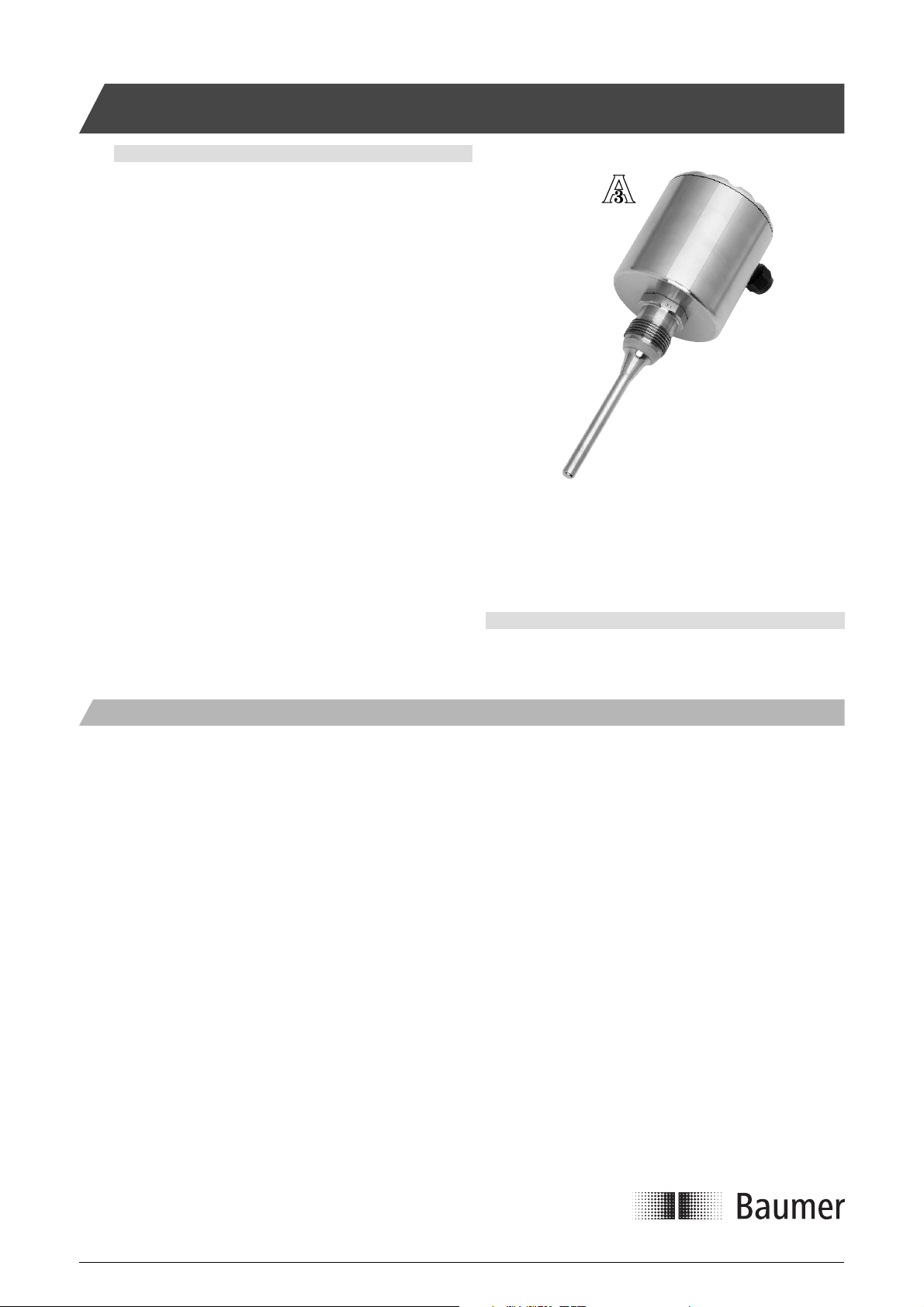
LSP 05X Potentiometric Level Transmitter
Safety instructions
This instrument is built and tested ac cord ing to the current EU-directives and packed in technically safe con di tion. In order to main tain this
condition and to ensure safe op er a tion, the user must follow the hints
and warnings given in this instruction.
During the installation the valid national rules have to be observed.
Ignoring the warnings may lead to severe per son al injury or substantial
damage to property.
The product must be op er at ed by trained staff. Correct and safe
operation of this equipment is de pend ent on proper transport, storage,
installation and op er a tion.
All electrical wiring must conform to local stand ards. In order to prevent
stray elec tri cal radiation, we rec om mend twisted and shielded input
cables, as also to keep power sup ply cables separated from the input
cables. The con nec tion must be made ac cord ing to the connecting
di a grams.
Before switching on the power supply take care that other equip ment
is not af fect ed. Ensure that the supply voltage and the conditions in the
environment comply with the spec i fi ca tion of the de vice.
Before switching off the supply voltage check the possible effects on
other equipment and the processing system.
LSP051
Description
The level measuring device LSP05X utilises the potentiometric meas-
urement principle and can be used in all medias that have a minimum
conductivity of 50 µS/cm.
From the low resistive measuring rod a high frequent current is fed
through the media to the tank wall. The voltage between the tip of the
rod and the tank wall is measured. This output voltage is proportional
to the tank fi lling level.
The measurement is unaffected by temperature and adhesive media.
The instrument is ideal for measurements in small wessels with tough,
pasty or strong adhesive media, such as ketchup, honey, and tooth-
paste. The integrated electronics provide a 4...20 mA output.
WARNING
This product contains no replaceable parts.
In case of malfunction the product must be shipped to Baumer for
repair.
The LSP has automatic recognition of top/buttom mounting position.
Even angled installation is possible. In a non-conductive tank such as
a plastic tank a reference rod must be installed.
Please observe that a non-linear conductivity in the media will affect
the accuracy of the measurement.
A version with separate rod sensor and electronics is available for
applications where the ambient temperature at the measuring point
exceeds 60°C. Due to the high temperature limit the LSP050 is well
suitable for CIP and SIP processes.
The hygienic installation is guaranteed by using one of the hygienic
weld-in sleeves. (Please refer to the separate data sheet).
Installation Manualwww.baumerprocess.com
Page 1 Design and specifi cations subject to change without notice
Page 2
Mechanical Installation
Welding part
Please refer to “Accessories” data sheet. The welding part has an
engraved mark or hole. When the product has been mounted and
correctly tightened the gland or M12 plug will align with this mark.
Make sure that the gland/plug is pointing downwards to prevent fl uids
from penetrating into the instrument.
Cautions
Use only the authorised special designed accessories.
The product warranty is void when installed with other adapters.
The sensor can not be shortened.
Please be aware of the active measuring zone on the rod
(see drawing)
Do not use tefl on, paper or other gaskets.
The process connection must have electrical contact with the tank.
if not, a separate grounding cable must be installed.
If the tank is non-conductive an additional ground electrode must be
installed. This should have electrical connection to the LSP process
connection.
Make sure that the rod can not touch the tank wall even with the highest movement of the media.
When installed <100 mm from the tank wall the rod must be parallel
with the tank wall. For larger distances non-parallelity can be allowed.
After carefully insertion of the sensor into the welding part tighten the
union with a torque of 20...30 Nm.
After Installation and Confi guration
Check the leak tightness of the sleeve.
Check the tightness of glands or M12 plugs.
Check the tightness of the cover.
Check that the rod is not touching the tank wall.
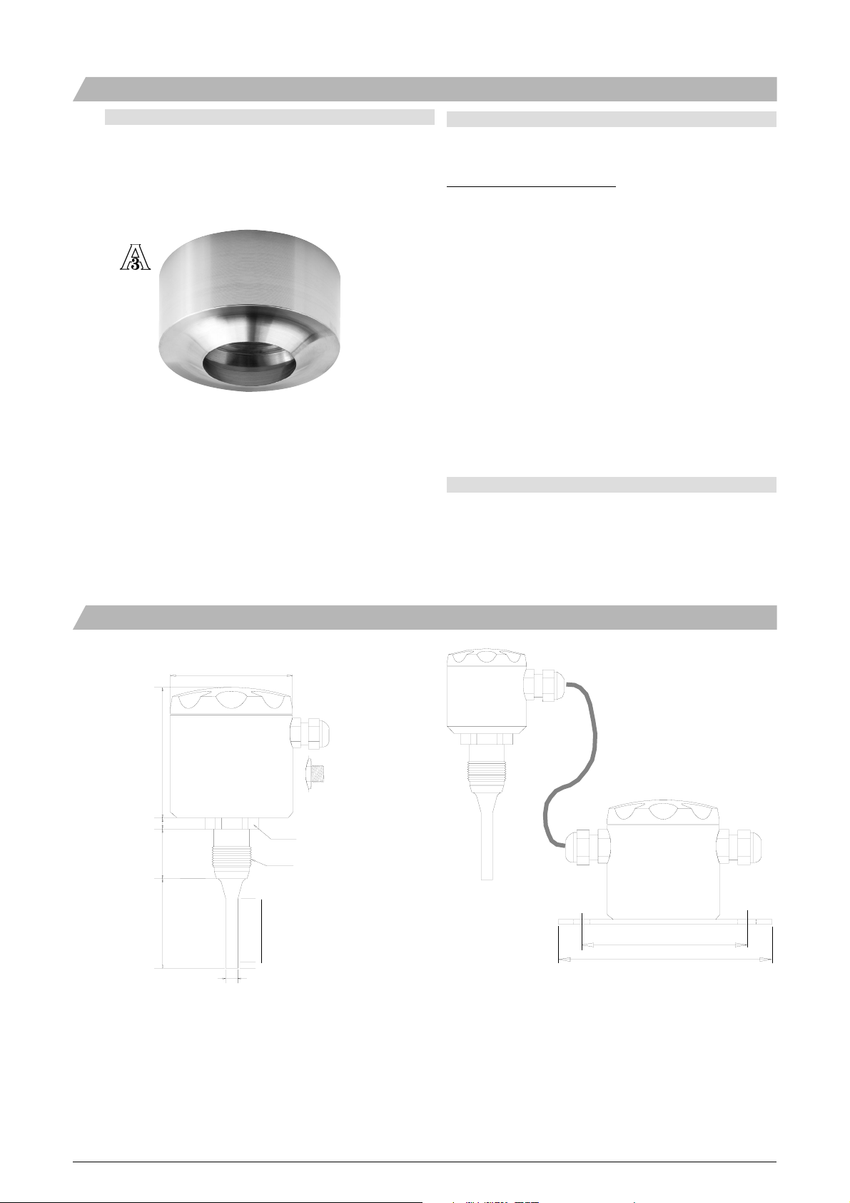
Dimensional Drawings
[mm]
ø89
Gland
92
M12 plug
8
33
L
ø10
LSP050/LSP051 - integrated electronics LSP055/LSP056 - separate electronics
AF36
G1
Active zone
5 mm
ø55 housing
Interconnection cable.
Specify length.
ø89 housing
ø8ø8
125
145
Installation Manualwww.baumerprocess.com
Page 2 Design and specifi cations subject to change without notice
Page 3

Electrical Installation
Push buttons >3 sec.
1 2 3 4
+-
18...36 Vdc
Connector LED Buttons M12 plug
+-
4...20 mA
to set 0% and 100%
Push both > 3 sec.
to reset.
Setpoint
100%; 20 mA
Setpoint
0%; 4 mA
18...36 Vdc (+) (+) 4...20 mA
1
2
4...20 mA (-)
(-)18...36 Vdc
4
3
1: Brown
2: White
3: Blue
4: Black
Operator Control
The green LED indicates that a supply voltage > 18 V with the correct
polarity is present.
The two red LEDs show different fl ashing rates according to the control
of the 4...20 mA output.
The sensor can be installed in the top or the buttom of the tank.
The sensor is calibrated for installation from the top. Then 4 mA output
corresponds to the tip of the rod, and 20 mA to the thread end.
When installed from the buttom of the tank an output excessive of 4
mA is obtained.
The sensor can be calibrated by pressing one of the two setpoint keys
for more than 3 seconds. The relevant LED will show a steady light.
With these two buttons any empty/full level can be confi gured on the
entire length of the rod.
The factory setting will be valid again by pressing both keys for more
than 3 seconds.
The “dry” signal level is adjusted together with the low level setting.
The “dry” indication is 2.4 mA output current.
Measuring Principle
Uout
to amplifi er
Ugen
100%
Caution
If different medias are used the low level adjustment should be made
with the media having the lowest conductivity.
Caution
The minus pole of the power supply is connected to the housing via a
protective diode.
However, the 4...20 mA output is galvanically isolated from the power
supply.
Theory
The liquid is stored in a ground connected tank.
The immersed level probe is a low resistance rod where the ends
are powered by an AC generator operating in the lower kiloherz
frequency range.
Between the rod and the tank wall is an endless amount of high level
resistances. Since they connect to the same potential (the tank wall)
they can be shown as two equivalent resistances, R1 and R2 con-
nected to an imaginary center point.
A high resistance input amplifi er is connected between the generator
and the tank wall.
0%
X%
R1
Since the generator is supplying a high range current it will create a
signifi cant voltage drop across the low resistance rod.
The resistances R1 and R2 form a voltage divider in range of the
immersed part of the rod. Output from this divider will indicate half
the level of the liquid. The amplifi er then calculate the actual level of
liquid from 0 to 100%.
The formula is:
Uout= 1/2 x media level (%) x Ugen
Media level (%) = Uout/Ugen x 2
R2
The level measurement is insensitive to adhesion.
Caution
It is very essential that the media conductivity is homogenious.
Otherwise R1 will not be equal to R2 and the output voltage will be
infl uenced.
Installation Manualwww.baumerprocess.com
Page 3 Design and specifi cations subject to change without notice
Page 4

Mounting of 3A Approved Products
Max. ± 85°
1)
2)
3)
Installation of 3A approved products:
1) Use only a 3A approved counter part.
2) The inspection hole should be visible and drained.
3) Mount the instrument in a self drained position.
4) Level the inner surface of the pipe with the counter part.
5) Weldings should be grinded to Ra= 0.8
4)
5)
Max. ± 175°
Refer to the data sheet “Accessories” for O-rings, gaskets and other
accessories.
The LSP 051 and LSP 056 are approved by 3A providing it is mounted
in a 3A approved counter part and installed according to the guidelines
given in the installation manual.
The 3A approved products fulfi ll the FDA demands and follow the
EHEDG guidelines regarding design, materials and fi nishing.
Refer to the 3A marked counter parts in the data sheet “Accessories”.
Example of Application
LSP Output
21.6 mA
21.6...20 mA
Set point 100% = 20 mA
5850-004_UK/2009-03-20/Rev. B1 This data sheet may only be reproduced in full.
20...4 mA
Set point 0% = 4 mA
4...2.4 mA
2.4 mA
Installation Manualwww.baumerprocess.com
Page 4 Design and specifi cations subject to change without notice
 Loading...