

Page 1
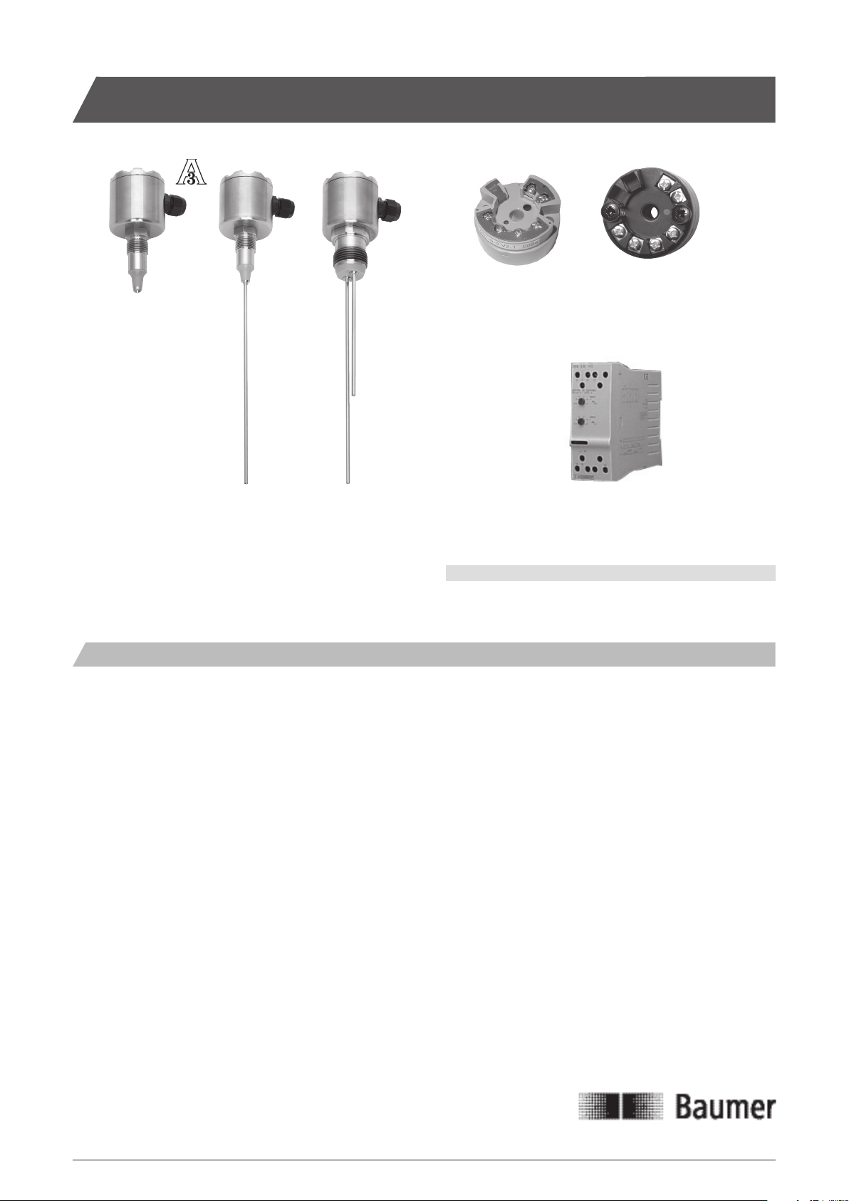
LSK Conductive Level Sensor
LSK320
LSK420 LSK350
Safety Instructions
This instrument is built and tested according to the current EU-direc-
tives and packed in technically safe condition. In order to maintain this
condition and to ensure safe operation, the user must follow the hints
and warnings given in this instruction.
During the installation the valid national rules have to be observed.
Ignoring the warnings may lead to severe personal injury or substantial
damage to property.
The product must be operated by trained staff. Correct and safe
operation of this equipment is dependent on proper transport, storage,
installation and operation.
All electrical wiring must conform to local standards. In order to prevent
stray electrical radiation, we recommend twisted and shielded input
cables, as also to keep power supply cables separated from the input
cables. The connection must be made according to the connecting
diagrams.
Before switching on the power supply take care that other equipment
is not affected. Ensure that the supply voltage and the conditions in the
environment comply with the specification of the device.
Before switching off the supply voltage check the possible effects on
other equipment and the processing system.
LKP100
Ver. 1
LKP100
Ver. 2
DNGA230100
WARNING
This product contains no replaceable parts.
In case of malfunction the product must be shipped to Baumer for
repair.
Installation Manualwww.baumer.com
Page 1 Design and specifications subject to change without notice
Page 2
Mechanical Installation
Welding part
Please refer to “Accessories” data sheet. The welding part has an
engraved mark or hole. When the product has been mounted and
correctly tightened the gland or M12 plug will align with this mark.
Make sure that the gland/plug is pointing downwards to prevent fluids
from penetrating into the instrument.
Cautions
Use only the authorised special designed accessories.
The product warranty is void when installed with other adapters.
The sensor can be shortened.
Coated rods: Remove approx. 10 mm of the coating from the rod tip to
ensure a proper contact to the media.
Do not use teflon, paper or other gaskets.
The process connection must have electrical contact with the tank.
if not, a separate grounding cable must be installed.
If the tank is non-conductive an additional ground electrode must be
installed. This should have electrical connection to the LSK process
connection.
Make sure that the rod can not touch the tank wall even with the highest movement of the media.
When installed <100 mm from the tank wall the rod must be parallel
with the tank wall. For larger distances non-parallelity can be allowed.
After carefully insertion of the sensor into the welding part tighten the
union with a torque of:
LSKx2x: 10...20 Nm.
LSKx5x: 20...30 Nm.
After Installation and Configuration
Check the leak tightness of the sleeve.
Check the tightness of glands or M12 plugs.
Check the tightness of the cover.
Check that the rod is not touching the tank wall.
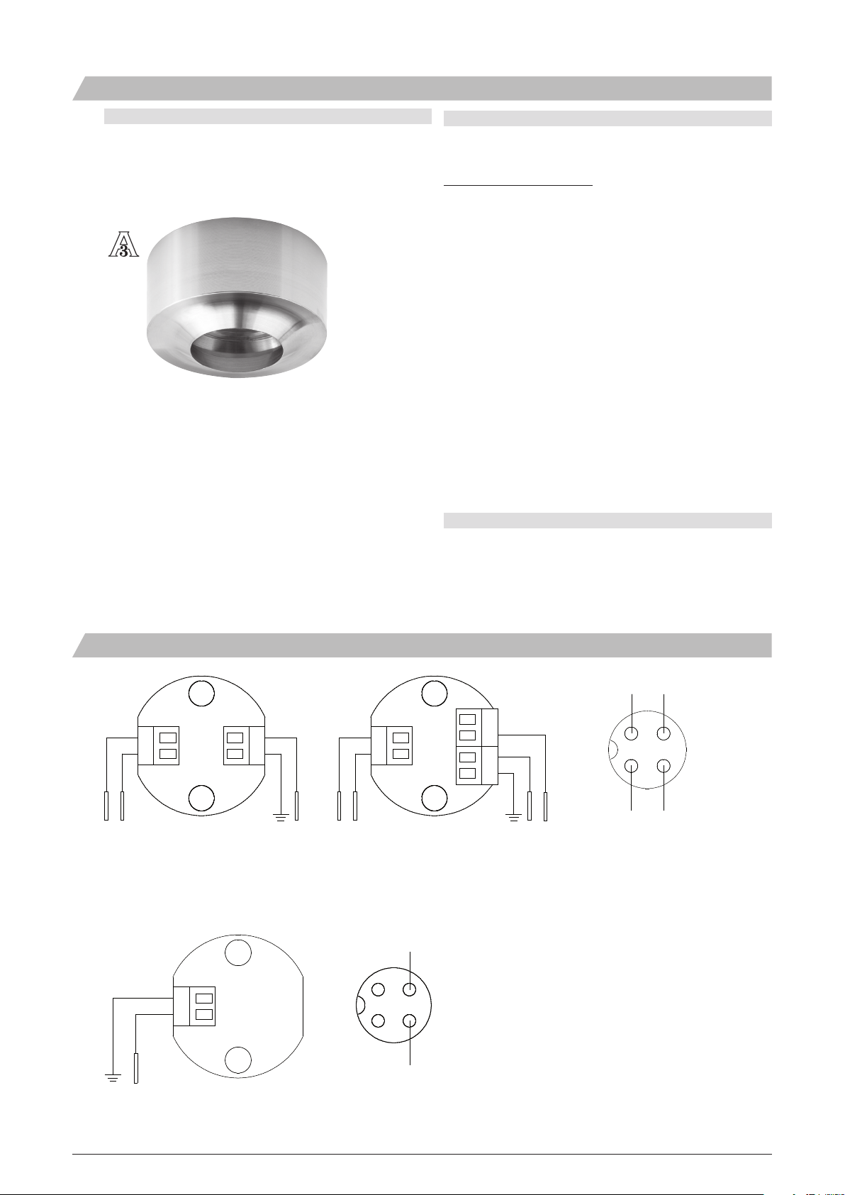
Electrical Installation
E3
E1
3
2
1
E2 E1 Gnd E3 E2 E1 Gnd E4 E3
2 or 3 rods 4 rods M12 plug
3
4
2
1
Connection terminal M12 Plug
E
2
1
Gnd
Input
1 4
2
3
4
5
6
WARNING:
Do not connect the LSK to a high DC potential, which could damage
the sensor. The most suitable evaluation module is a type with a
sensing frequency > 200 Hz and input voltage < 5Vrms.
1
2
E2
4
3
Gnd
1: Brown
2: White
3: Blue
4: Black
Gnd E
Gnd
1 rod
Installation Manualwww.baumer.com
Page 2 Design and specifications subject to change without notice
Page 3

Electrical Installation - LKP100 Amplifier for In-head Mounting
M12 Plug
Input
5
6
Gnd
Output load
max. 50 mA
Input
5
6
Gnd
Output load
max. 50 mA
0 mA
50 mA
50 mA
0 mA
LED
LED
+
4
1
2
3
S
-
+
4
1
2
3
S
-
+
18...36 Vdc
-
+
18...36 Vdc
-
4
3
S
2
1
4
3
S
2
1
Sensibility Connection Typical application
20 KOhm
Terminal S connected to + (plus) Water
2 KOhm Terminal S not connected Beer, juice, youghurt
200 Ohm
Note: Terminal S is for local or remote setting of the sensibility.
Terminal S connected to - (minus) Acid, Alkalis
Electrical Installation - DNGA 230100
1: Brown
2: White
3: Blue
4: Black
ø7
33
ø44
Refer to Installation manual 5511-507.
DNGA230100
Installation Manualwww.baumer.com
Page 3 Design and specifications subject to change without notice
Page 4

Mounting of 3A Approved Products
Max. ± 85°
1)
2)
3)
Installation of 3A approved products:
1) Use only
2) The inspection hole should be visible and drained.
3) Mount the instrument in a self drained position.
4) Level the inner surface of the pipe with the counter part.
5) Weldings should be grinded to Ra= 0.8
a 3A approved counter part.
4)
5)
Max. ± 175°
Refer to the data sheet “Accessories” for O-rings, gaskets and other
accessories.
The LSK32x, LSK42x, LSK52x, LSK 35x and LSK 45x are approved
by 3A providing it is mounted in a 3A approved counter part and
installed according to the guidelines given in the installation manual.
The 3A approved products fulfill the FDA demands and follow the
EHEDG guidelines regarding design, materials and finishing.
Refer to the 3A marked counter parts in the data sheet “Accessories”.
5850-003_UK/2009-12-02/Rev. B1 This data sheet may only be reproduced in full.
Installation Manualwww.baumer.com
Page 4 Design and specifications subject to change without notice
 Loading...