

Page 1
Operators instructions
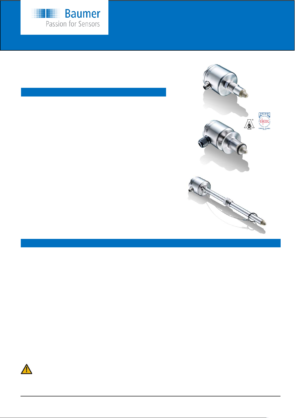
CleverLevel switch, LFFS
CleverLevel switch, type LFFS is an universal level switch, which
can be used for all applications in liquids and solids with a DK-value
above 1,5
Safety instructions
This instrument is constructed and tested according to the current EUdirectives and packed in technically safe condition. In order to maintain
this condition and to ensure safe operation, the user must follow the
instructions and warnings given in this instruction.
During the installation local standards have to be observed. Ignoring the
warnings may lead to severe personal injury or substantial damage to
property.
The product must be operated by trained staff. Correct and safe operation of this equipment is dependent on proper transport, storage, installation and operation.
All electrical wiring must conform to local standards and the connection
must be made according to the connecting diagrams.
Before switching on the power supply take care that other equipment is
not affected. Ensure that the supply voltage and the conditions in the
environment comply with the specification of the device.
Before switching off the supply voltage check the possible effects on
other equipment and the processing system.
To obtain the specified protection degree, the LFFS must be mounted
with a compliant cable.
Description
The Level Switch LFFS designed to detect levels in tanks, media separation and provide empty-pipe detection or dry-run protection
for pumps.
A high frequency sweep signal is radiated from the sensor tip into the tank. The media will act as a virtual capacitor, which together
with a coil in the sensor head, will form a circuit creating the switch point signal. This virtual capacity will depend of the di-electric
value (DK-value) of the media.
By means of the FlexProgrammer 9701 the output can be configured to either NPN, PNP or digital output signal. A damping of the
output signal can be activated in case of a fluctuating media level, e.g. during tank filling.
The measurement is precise and unaffected by the mounting position in the tank. In the Flex-software a compensation for foam,
bubbles and condensate as well as viscous media can be set.
The Flex-software also features an adjustment facility making the user able to adjust the sensor to a specific media.
The Level Switch LFFS measures liquids such as water and beer as well as viscous, sticky fluids, such as honey, yoghurt, toothpaste and ketchup. Even dry medias can be measured, e.g. sugar or flour.
The Level Switch LFFS is resistant against CIP and SIP agents.
Hygienic installation is also possible with the comprehensive range of accessories, see the overview at page 6.
WARNING
When the top cover is removed, do not look directly at the blue LED with unshielded eyes or damage to retina may occur !
This product contains no replaceable parts. In case of malfunction the product must be shipped to Baumer for repair.
www.baumer.com
Operators instructions: 11109132 02 EN Page 1 / 12
2013-08-23 Design and specifications subject to change without notice
Page 2
Operators instructions
CleverLevel switch, LFFS
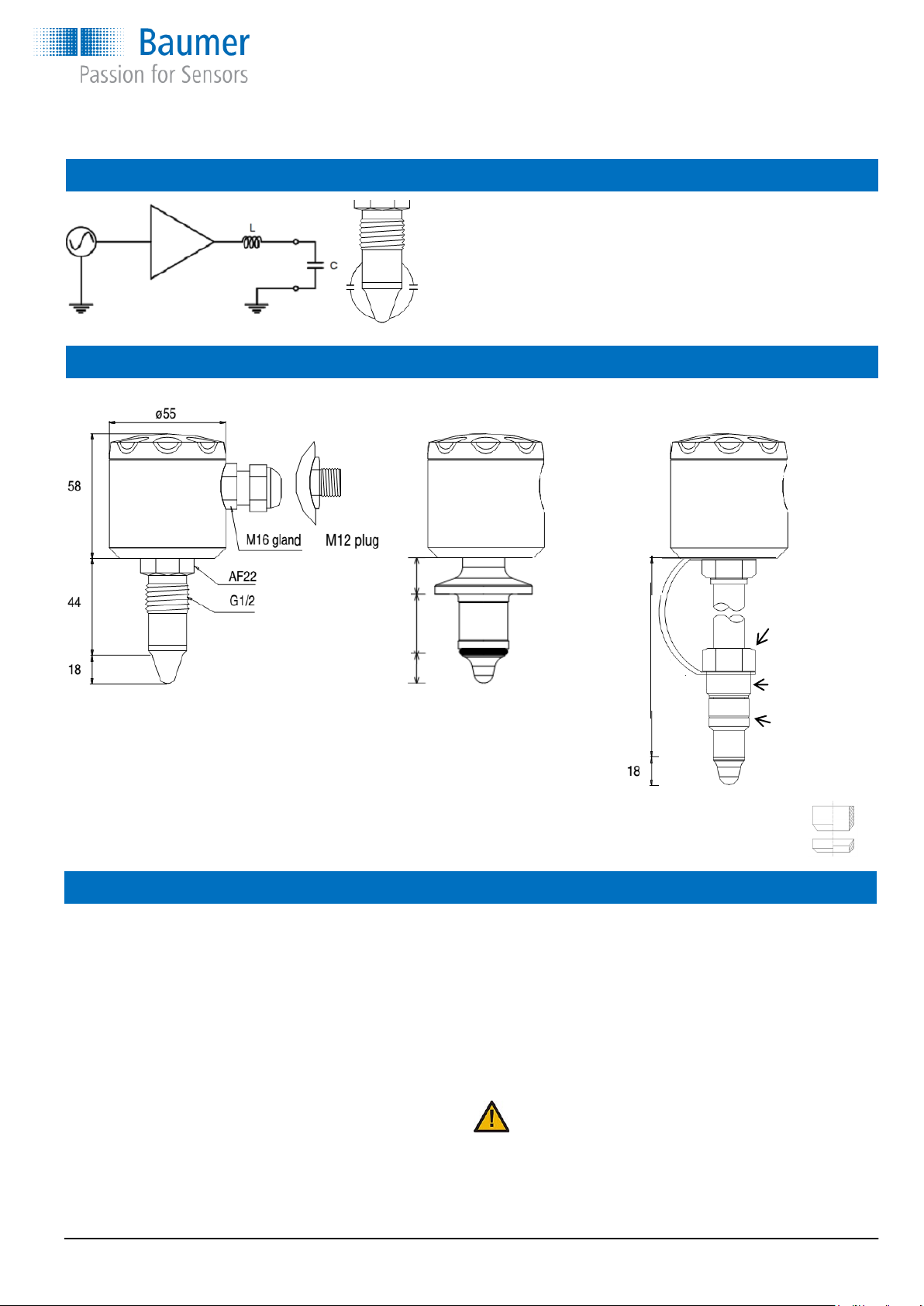
Measuring principle
The capacity (C) of the media is directly proportional to the dielectric
value of the media.
A frequency between 100 and 180MHz is swept into the media.
When the coil (L) and the capacitor (C) reach a resonance frequency,
it will be detected by the electrical circuit.
Dimensions
G½ hygienic 3A DN38 hygienic G½ hygienic sliding connection
19,0
31,5
14,5
Mounting
Please refer to “Accessories” data sheet. The welding part has
an engraved mark or a leak hole. When the product has been
mounted and correctly tightened the gland or M12 plug will
align with this mark.
Make sure that the gland/plug is pointing downwards to prevent fluids from penetrating into the instrument.
Use only the authorised special designed accessories. The
product warranty is void when installed with other adapters.
Do not use PTFE, fibre or other gaskets. The PEEK tip against
the stainless steel welding part will perform a hygienic tightening provided that the guidelines have been followed.
Due to the measuring principle it is essential that the sensor tip
can “see” an ample amount of the metal shaft or welding part.
Safety
wire
100
or
250
Mounting instructions for sliding connection:
1) Clean the sliding shaft.
2) Mount the smallest ring against the media as indicated.
3) Tighten the G1/2 Hygienic sliding nipple at 25...30 Nm.
4) Replace the Washer ring kit when one or both parts are
permanently deformed or stick to the shaft of the sliding
connection.
WARNING
The Level Switch LFFS with sliding connection can be mounted
in installations with a static pressure up to 16 bar.
To prevent personal injuries or property damage it is essential
that the safety wire is mounted correctly and is undamaged.
Sliding
connection
G½
2 × PEEK
sealing
washers
Spare part set:
4401.8001
www.baumer.com Operators instructions: 11109132 02 EN Page 2 / 12
Page 3
Mounting
Operators instructions
CleverLevel switch, LFFS
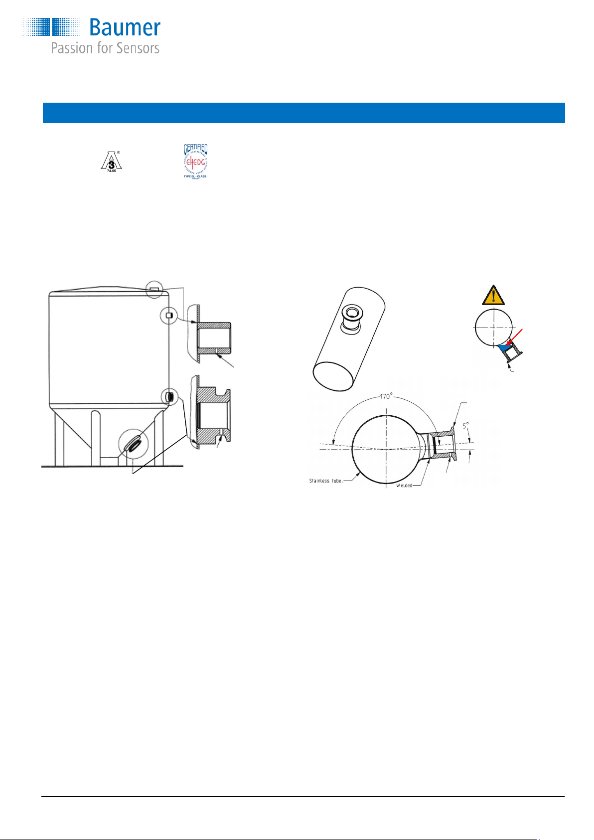
Installation of 3A approved and EHEDG certified products:
1) Use only a 3A approved counter part.
2) The inspection hole should be visible and drained.
3) Mount the instrument in a self drained position.
4) Level the inner surface of the pipe with the counter part.
5) Welding's should be grinded to Ra= 0.8
Example
with PM023
Tighten the union with a torque of:
Std. version 20...25 Nm.
Sliding connection 25...30 Nm.
WARNING
Cannot be
drained
Fitted
incorrect
Example
with 8126-928
Example
with 8126-916
After installation and configuration
Check the leak tightness of the sleeve.
Check the tightness of glands or M12 plugs.
Check the tightness of the cover
Leakage indication hole
must be places downwards
www.baumer.com Operators instructions: 11109132 02 EN Page 3 / 12
Page 4
Operators instructions
CleverLevel switch, LFFS
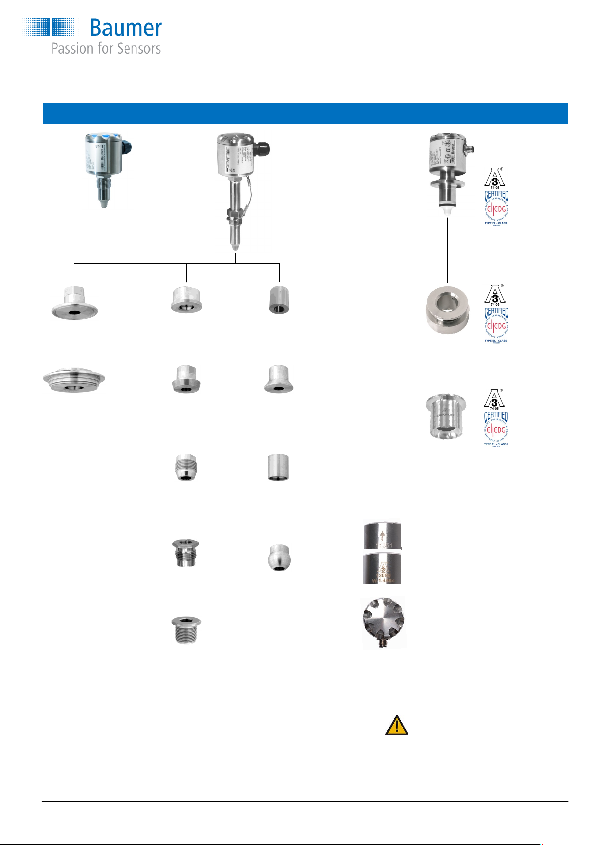
Mounting connections
ISO2852 SMS 1145 Welding
DN38: CAM023.505 DN51: SAM020.051.1 for tank
DN51: CAM023.640 PM023
Variline, type N DIN 11851 Welding
VAM023 DN25: MAM020.025 for tank
DN40: MAM020.040 PM021
DN50: MAM020.050
Adapter Welding
G½ → G1 to pipe end
RAM020.1 DN25...50: PM022.1
DN65...100: PM022.2
Adapter Welding Ø35
1” level switch for tank/tube
LAM020.3 PM025
Adapter, industrial
G½ → G1
RAM020.2
Welding
for tank
8126916
Welding
for pipe end
8126928
On a welding adapter there is an
arrow or a 3A logo.
This must be placed upwards when
welding the adapter into a tank
(horizontal position).
This assures that the electrical connection will be pointing downwards
(opposite of the arrow; 3A logo)
Refer to data sheet ”Accessories Universal” for further
information
NOTE:
The LFFS must be mounted in a Baumer mounting
connection. If not, Baumer do not guarantee correct
function or tightness.
www.baumer.com Operators instructions: 11109132 02 EN Page 4 / 12
Page 5

Operators instructions
CleverLevel switch, LFFS
Media temperature and external length for sliding connection
LFFS-xx1.x / LFFS-xx2.x LFFS-xx3.x and LFFS-xx4.x
Media temperature °C
120
115
110
105
100
95
90
85
80
75
50 55 60 65 70 75 80 85 90
Ambient temperature °C
For CIP/SIP Media temperature, max. 140°C
Ambient temperature, max. 60°C
Duration, max. 1 hour
External length
Media temperature °C
See example
External length of sliding connection
It is essential that the max. ambience temperature for the electronics
is never exceeded (85°C). For ATEX approved products please refer
ATEX data.
Example, how to read External length curve:
Example: Media temperature / Ambient temperature / External length
160°C 60°C 120 mm
A 250 mm sliding connection is mounted in a tank with a total in-
The drawing shows how the sliding connection can be
used for at least 4 applications:
1) Mounted at the top of a tank to adjust to a
maximum level.
2) Serving as a cooling neck in high media
temperature applications.
3) Adjusted to place the sensor tip deeper
inside the tank.
4) To reach in through insulation material.
sert length of 130 mm. Hence the external length of the sliding
connection will be 250 – 130 = 120 mm.
The media temperature will be max. 160 °C.
Read the x-axis at 120 mm an the y-axis at 160°C and find that
the ambient temperature must be kept below 60°C.
In case the radiated heat from the tank will cause a higher ambient
temperature at the housing efficient insulation of the tank must be
established.
When re-ordering a CleverLevel switch
If a new CleverLevel switch is installed in an existing application, it is normally a “plug-n’-play” operation.
If the settings of the level switch was changed from standard factory settings, it is necessary to re-adjust the new switch to same
as the “old” switch. It is possible to save the settings of the “old” switch on the PC and download those again to the new level
switch.
The factory setting of the sensitivity of the media may vary up to ±5%. This means that if an very exact set point is required, a new
teach-in or adjustment by the FlexProgram must be performed.
www.baumer.com Operators instructions: 11109132 02 EN Page 5 / 12
Page 6

Operators instructions
CleverLevel switch, LFFS
Teach-In using the FlexProgram and FlexProgrammer 9701
Sophisticated settings for Teach-In as well as output type, diagnostics, data logging, tag no. and damping can be configured using
the FlexProgrammer 9701. Integrated HELP-menus will give full instruction.
Using the FlexProgrammer 9701 alone and Teach-In
FlexProgrammer 9701 stand alone menu
Press
Turn on FlexProgrammer if in sleep mode
Empty configuration
Search for product
LFFS/LBFS configuration
Product LFFS / LBFS
TAG number xxxxxxxxxxxxxxx
Range min. x.x%
Range max. xx.x%
Damping x,x sec
Output config. Xxxxxxx
Trigger level xx,x%
Range hyst. x,xx%
Trigger hyst. x.xx%
Press or to browse the menus
to access current menu point
to return to previous menu
and simultaneously to reset FlexProgrammer
and go in sleep mode
Teach-In
Press
and simultaneously
Select Menu “Teach-In”
Search for product
= Product LFS/LBFS
At empty tank setting 0%
At full tank setting 100%
Manually Teach-In
Make sure that power is on before Teach-In.
For best Teach-In it is important the product is fixed in the final application.
During Teach-In mode the light intensity of the LED will decrease, please protect your eyes.
Step To do LED Result
Connect terminal ”Teach-In” to
1
- VDC (T1 or T2) for 3,5 second
With no media present connect
2
”Teach-In” to - VDC shortly
With media present connect
3
”Teach-In” to - VDC shortly
NOTE:
If the media is sticky, foamy, powdery or in other ways leaving parts of the media at the sensor tip this situation has to be established also during the Teach-In process. Otherwise a faulty calibration can be the result.
If Teach-In for some reason do not succeed, the CleverLevel Switch LFFS will enter “Error State” and automatically reload factory
settings . The factory settings can always be reloaded by connecting the terminal “Teach-In” to -VDC for more than 6.5 seconds.
A reloaded factory settings will be confirmed by pulsing light intensity 3 times.
Error state description LED Result
Flash 1 time per second
Light on for 2 second and then flash
Light on for 2 seconds
Ready for Teach-in
Register ”empty” state. Pls. See note
Register ”full” state, stores the value and returns to
Normal operation with new setting
Error state Blinking, 3 × short and 1 × long Can normally be fixed by powering off and on and remake the Teach-In.
Alternatively remake the Teach-In configuration by use of the FlexProgram and the FlexProgrammer 9701
www.baumer.com Operators instructions: 11109132 02 EN Page 6 / 12
Page 7

Electrical connection
Electrical specifications:
Power supply 12,5...36 VDC, 35 mA max.
Output PNP, NPN or Digital
Max. 50 mA, short-circuit and high
temperature protected
Active “Low” NPN and Digital output
(-VDC +2,5V) ±0,5V, R
Active “High” PNP and Digital output
(+VDC -2,5V) ±0,5V, R
load
load
1 kΩ
1 kΩ
Operators instructions
CleverLevel switch, LFFS
M12 plug: 1 Brown
2 White*
3 Blue
4 Black
* To avoid unintended Teach-In, be aware not to
connect the Teach-In pin or expose it to any
electrical noise during normal operation.
Normally open - NO
Normally closed - NC
5
1
2
5
1
2
5
1
2
5
1
2
5
1
2
5
1
2
www.baumer.com Operators instructions: 11109132 02 EN Page 7 / 12
Page 8

ATEX
Operators instructions
CleverLevel switch, LFFS
Conditions for Ex certification
Connection type Ambient temperature Media temperature
G½ hygienic -40 … +85 °C +85 °C
3A DN38
100 mm -40 … +85 °C +85 °C
Sliding connection
250 mm -40 … +85 °C +85 °C
Sliding connection
ATEX Gas ia
Ex ia IIC T5, ATEX II 1G - Installation
A Level Switch LFFS-1xx.x is Ex ia IIC T5, ATEX II 1G approved for application in hazardous areas in accordance with
the current EU directives. The product must be installed in
accordance with prevailing guidelines for zone 0 with a barrier
Ex-data
Supply range 24...30 VDC
Temperature class T1...T5 Pls. see above table
Internal inductivity Li <10 µH
Internal capacity Ci <33 nF
Barrier data U <30 VDC
I <0.1 A
P <0.75 W
Note:
There is an electrical connection between intrinsic safe circuit
and housing due to the measurement principle
Note
(max. allowed)
-40 … +60 °C +95 °C 1)
-40 … +40 °C +115 °C 1)
-40 … +60 °C +155 °C 1)
-40 … +40 °C +175 °C 1)
-40 … +60 °C +195 °C 1)
-40 … +40 °C +200 °C 1)
LFFS-1xx.x
with NPN output
NPN out
LFFS-1xx.x
with PNP output
Note:
For NPN output only!
A standard barrier may be used
Standard barrier
Note:
For PNP output the barrier module
PFOFSI3-B25100-ALG-LS
is required for functional purposes.
1) Provided that
the sensor tip
at the instru ment is the
only part in
contact with
the media
Two-channel
ZENER barrier
Safe area
+ 22...120 VDC
PFOFSI3-B25100-ALG-LS
www.baumer.com Operators instructions: 11109132 02 EN Page 8 / 12
or
- 90...253 VAC
Page 9

Operators instructions
CleverLevel switch, LFFS
ATEX Dust tD
A Level Switch LFFS-2xx.x is Ex tD A20 IP67 T100°C, ATEX II 1D
approved for application in hazardous areas in accordance with the
current EU-directives. The product must be installed in accordance
with prevailing guidelines for zone 20 without a barrier.
Ex-data
Supply range VDC 12,5...30
Load I <0.1 A
Temperature class T1...T5 Pls. see table top page 8
ATEX Gas nA
A Level Switch LFFS-3xx.x is Ex nA II T5, ATEX II 3G approved for
application in hazardous areas in accordance with the current EU
directives. The product must be installed in accordance with prevailing
guidelines for zone 2 without a barrier.
Ex-data
Supply range VDC 12,5...30
Load I <0.1 A
Temperature class T1...T5 Pls. see table top page 8
5
1
2
12,5...30 VDC
5
1
2
12,5...30 VDC
Ex-Configuring
The FlexProgrammer 9701 configuring unit must not be connected to the CleverLevel
Switch LFFS within the hazardous area.
Configuring procedure:
a) Disconnect mains from the 4...20 mA loop circuit.
b) Disconnect the Level Switch from the circuitry within the hazardous area.
c) Uninstall and bring the Level Switch to the safe area.
d) Connect the FlexProgrammer 9701 and perform the configuring session.
e) Re-install the Level Switch in the hazardous area.
f) Connect the power supply to the circuit.
Outside hazardous area
Links
Operation instructions in other languages and certificates can be found on Baumer home page
Operation instructions www.baumer.com → downloads → certificates-approvals → product main group
Certificates ATEX / DNV www.baumer.com → downloads → certificates-approvals → certificate / approval
WHG certificate/instruction leakage www.baumer.com/LxFS-WHG-Leak
WHG certificate/instruction overfill www.baumer.com/LxFS-WHG-Overfill
www.baumer.com Operators instructions: 11109132 02 EN Page 9 / 12
Page 10

WHG leakage approval
Operators instructions
CleverLevel switch, LFFS
www.baumer.com Operators instructions: 11109132 02 EN Page 10 / 12
Page 11

WHG overfill protection approval
Operators instructions
CleverLevel switch, LFFS
www.baumer.com Operators instructions: 11109132 02 EN Page 11 / 12
Page 12

Operators instructions
CleverLevel switch, LFFS
WHG leakage and overfill protection approval
www.baumer.com Operators instructions: 11109132 02 EN Page 12 / 12
 Loading...