

Page 1
Betriebsanleitung
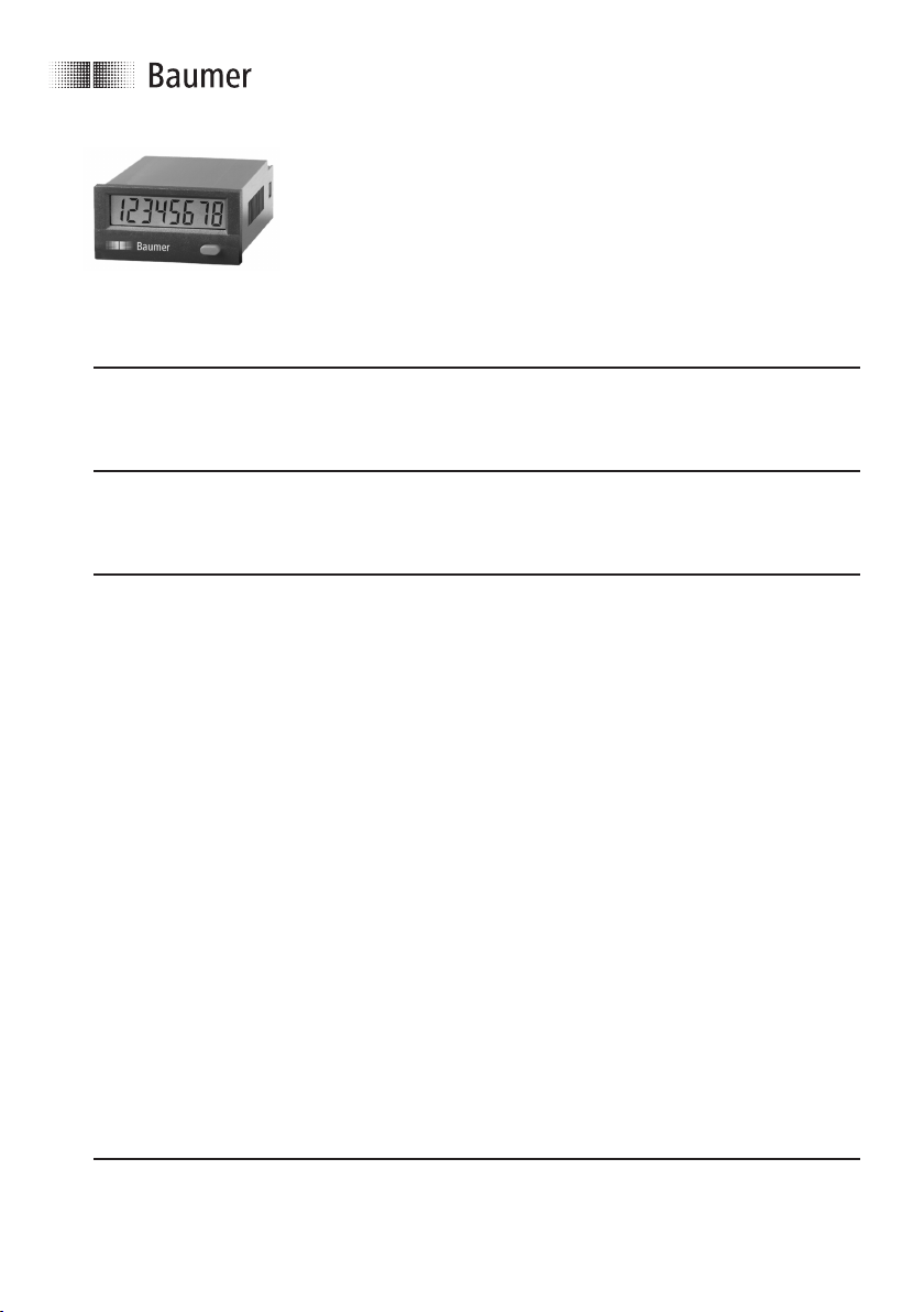
Anzeigezähler
ISI30, ISI31, ISI32, ISI33
Operating instructions
Display counter
ISI30, ISI31, ISI32, ISI33
Instructions d’utilisation
Compteurs à affichage
ISI30, ISI31, ISI32, ISI33
ensor Solutions
S
Motion Control
Vision Technologies
Process Instrumentation
Baumer IVO GmbH & Co. KG 04/10 · 171.55.256/4
Dauchinger Strasse 58–62 · DE -78056 Villingen-Schwenningen
Phone +49 (0)7720 942 -0 · Fax +49 (0)7720 942-900
info.de@baumerivo.com · www.baumer.com
Page 2
ISI30, ISI31, ISI32, ISI33
!
!
Betriebsanleitung
LCD-Anzeigezähler
isiLine 30/31/32/33
Beschreibung
ie isiLine Anzeigezähler sind batteriebetrieben. Die Ansteuerung
D
erfolgt über potentialfreie Kontakte oder Spannungsimpulse. Sie
assen sich in unterschiedlichen Applikationen einsetzen, wie z.B.
l
ummenzählung, Stückzählung, Positionserfassung,
S
Differenzzählung usw.
Die verschiedenen Typen mit spezifischen Eingangsarten lassen
sich mittels Steuereingängen zusätzlich erweitetern und auf fast
alle Anwendungen anpassen.
1.1 Vorwort
Lesen Sie vor der Montage und der Inbetriebnahme
diese Bedienungsanleitung durch. Beachten Sie zu
Ihrer eigenen Sicherheit und der Betriebssicherheit
alle Warnungen und Hinweise. Wenn das Gerät nicht
nach der Bedienungsanleitung benutzt wird, kann
der vorgesehene Schutz beeinträchtigt werden.
1.2 Sicherheits- und Warnhinweise
Benutzen Sie das Gerät nur in technisch einwandfreiem Zustand, bestimmungsgemäß, sicherheits-
und gefahrenbewusst unter Beachtung dieser
Bedienungsanleitung. Die geltenden
Sicherheitsnormen für elektrische Installationen sind
ebenso zu beachten.
1.3 Bestimmungsgemäßer Gebrauch
Der Einsatzbereich dieses Geräts liegt in industriellen Prozessen
und Steuerungen. In den Bereichen von Fertigungsstraßen der
Metall-, Holz-, Kunststoff-, Papier-, Glas- und Textilindustrie u.ä
mit einem Verschmutzungsgrad von 2. Überspannungen an den
Schraubklemmen des Geräts müssen auf den Wert der Überspannungskategorie II begrenzt sein. Das Gerät ist nicht geeignet für
den explosionsgeschützten Bereich und den Einsatzbereichen,
die in EN 61010 Teil 1 ausgeschlossen sind. Das Gerät darf nur
als Einbaugerät in Innenräumen eingesetzt werden. Unter
bestimmten Vorraussetzungen ist ein Betrieb aber auch im
Außenbereich zulässig.
Es darf bis zu einer Höhe von 2.000 m über N.N. verwendet werden. Jeder darüber hinausgehende Gebrauch gilt als nicht
bestimmungsgemäß.
Wird das Gerät zur Überwachung von Maschinen oder
Ablaufprozessen eingesetzt, bei denen infolge eines Ausfalls
oder Fehlbedienung des Gerätes eine Beschädigung der
Maschine oder ein Unfall des Bedienungspersonals möglich ist,
dann müssen Sie entsprechende Sicherheitsvorkehrungen treffen.
1.4 Schalttafeleinbau
Montieren Sie das Gerät entfernt von Wärmequellen
und vermeiden Sie direkten Kontakt mit ätzenden
lüssigkeiten, heißem Dampf oder ähnlichen. Achten
F
ie bei der Installation auf eine ausreichende
S
Kühlung des Gerätes.
1.5 Montageanleitung
– Befestigungsrahmen vom Gerät abziehen.
Gerät von vorne in den Schalttafelausschnitt einsetzen und auf
–
orrekten Sitz der Frontrahmendichtung achten.
k
– Befestigungsrahmen von hinten auf das Gehäuse aufschieben,
is die Federbügel unter Spannung stehen und die Rastnasen
b
oben und unten eingerastet sind.
1.6 Elektrische Installation
Dieses Gerät wird mit einer internen Batterie versorgt.
– Um die Brandschutzvorschriften einzuhalten, dür-
fen im Fehlerfall am Zähler 8 A/150 VA nicht überschritten werden!
– Die vom Gerät nicht belegten Klemmen dürfen
nicht beschaltet werden.
– Die Anschlussbelegung der Stecker sowie die max.
zulässigen Werte sind unbedingt einzuhalten.
– Um die CE-Konformität zu erreichen, ist eine EMV-
gerechte Installation Vorraussetzung.
1.7 Hinweise zur Störsicherheit
Alle Anschlüsse sind gegen äußere Störeinflüsse geschützt. Der
Einsatzort ist so zu wählen, dass induktive oder kapazitive
Störungen nicht auf das Gerät oder dessen Anschlussleitungen
einwirken können! Durch geeignete Kabelführung und
Verdrahtung können Störeinflüsse (z.B. von Schaltnetzteilen,
Motoren, getaktete Reglern oder Schützen) vermindert werden.
1.8 Erforderliche Maßnahmen:
– Für Signal- und Steuerleitungen nur geschirmtes Kabel
verwenden.
– Kabelschirm beidseitig auflegen.
– Litzenquerschnitt der Leitungen min. 0,14 mm².
– Der Anschluss der Abschirmung an den Potentialausgleich
muss so kurz wie möglich und großflächig (niederimpedant)
erfolgen.
– Verbinden Sie die Abschirmungen nur mit der Schalttafel, wenn
diese auch geerdet ist.
– Bei Problemen durch Erdschleifen ist der Schirm auf der
Auswerteseite impedanzarm und auf der Geberseite über einen
Kondensator mit ca. 100nF an Bezugserde anzuschließen.
– Das Gerät muss in möglichst großem Abstand von Leitungen
eingebaut werden, die mit Störungen belastet sind.
– Leitungsführungen parallel zu Energieleitungen vermeiden.
– Leitungen und deren Isolierungen müssen dem vorgesehenen
Temperatur- und Spannungs- und Leistungsbereich entspre-
chen. Es gelten die Normen des jeweiligen Landes.
DC-Ausführungen:
Damit Sie die maximale EMV-Festigkeit erreichen, müssen Sie für
die Zähl- und Steuereingänge geschirmte Leitungen verwenden,
oder nicht verwendete Zähleingänge mit GND (0 V) verbinden.
2 www.baumer.com
Page 3

ISI30, ISI31, ISI32, ISI33
AC-Ausführungen:
amit Sie die maximale EMV-Festigkeit erreichen, müssen Sie für
D
die Steuereingänge geschirmte Leitungen verweden.
1.9 Inbetriebnahme
– Ist das Gerät richtig eingestellt und programmiert (Funktion;
ei Zählern max. Zählfrequenz)?
b
1.10 Fehlermöglichkeiten und deren Ursachen
astatur lässt sich nicht bedienen:
T
Tastaturverriegelungseingang aktiviert
-
Zähler zählt nicht:
- Zähleingang falsch oder verdreht angeschlossen
- Falsche Eingangssignal für den Impulsgeber eingestellt
- Polarität (NPN/PNP) vertauscht
- keine Masseverbindung zwischen Impulsgeber und Zähler
Maximale Zählfrequenz überschritten
-
- Signalpegel erreichen die Schaltschwelle des Zählers nicht
Sollte Ihr Gerät trotz allem nicht funktionieren, so wenden Sie
ich bitte an die für Sie zuständige Vertretung ganz in Ihrer Nähe,
s
der rufen Sie direkt bei der technischen Beratung in unserem
o
Hause an.
ei Rücksendungen bitten wir um eine kurze Beschreibung des
B
Fehlers, der Programmierung und des Anschlußbildes, um einen
eventuell vorhandenen Fehler nachvollziehen zu können und eine
eparatur Ihres Gerätes möglichst schnell durchführen zu können.
R
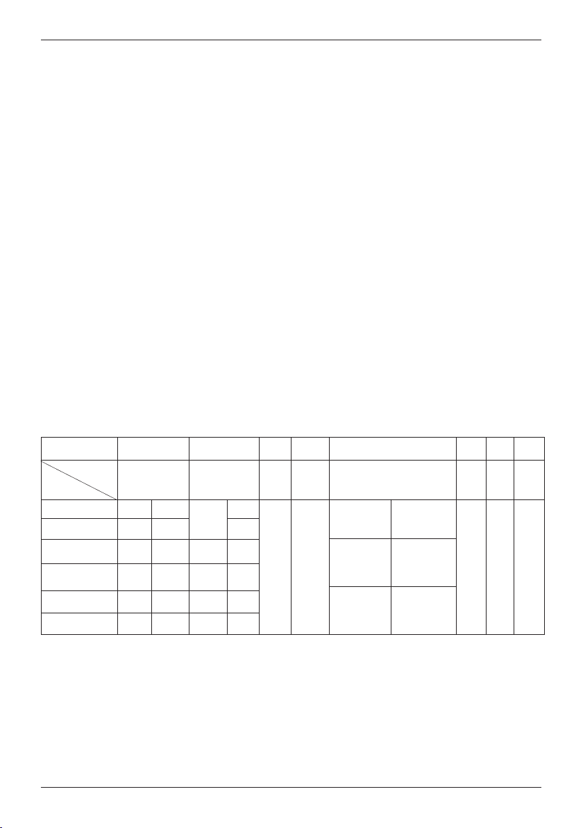
Typenübersicht:
Type Eingangsart Zähleingänge
INP A INP B
ISI30.010AX01
ISI30.012AX01
ISI30.013AX01
ISI31.010AX01
ISI31.011AX01
ISI31.013AX01 AC/DC
ISI32.013AX01
ISI33.010AX01
ISI33.011AX01
Tabelle 1
Count
Cnt.Dir/Up.Dn
Up.Dn
Cnt.Dir
Quad/Quad2
00 ... 0,7 V DC NPN 7 kHz 00 ... 0,7 V DC
04 ... 30 V DC PNP 12 kHz
10 ... 260 V AC/DC AC/DC 30 Hz
00 ... 0,7 V DC
04 ... 30 V DC
10 ... 260 V AC/DC
10 ... 260 V AC/DC
00 ... 0,7 V DC
04 ... 30 V DC
NPN
PNP
AC/DC
NPN
PNP
Optionen: x = A: ohne Hintergrundbeleuchtung
00 ... 0,7 V DC
10 ... 260 V AC/DC
7 kHz
00 ... 0,7 V DC
12 kHz
04 ... 30 V DC
30 Hz
10 ... 260 V AC/DC
30 Hz
10 ... 260 V AC/DC
3 kHz
00 ... 0,7 V DC
6 kHz
04 ... 30 V DC
x = B: mit Hintergrundbeleuchtung
NPN
NPN
AC/DC
NPN
PNP
AC/DC
AC/DC
NPN
PNP
30 Hz
0–
7 kHz
12 kHz
30 Hz
30 Hz
3 kHz
6 kHz
h
c
s
t
u
e
d
Eingangsarten DC:
Count: Schneller und langsamer Zähleingang
INP A: Zähleingang schnell
INP B: Zähleingang langsam
Cnt.Dir: Zähleingang und Zählrichtungseingang
INP A: Zähleingang
INP B: Zählrichtungseingang
Up.Dn: Differenzzähleingang
INP A: Zähleingang addierend
INP B: Zähleingang subtrahierend
Quad: Phasendiskriminatoreingang
INP A: Zähleingang 0°
INP B: Zähleingang 90°
Quad2: Phasendiskriminatoreingang mit
Impulsverdopplung
INP A: Zähleingang 0°
INP B: Zähleingang 90°
Jede Flanke von INP A wird gezählt.
Eingangsarten AC:
Count: Zähl- und Rücksetzeingang
INP A: Zähleingang AC/DC
INP B: Rücksetzeingang AC/DC
Cnt.Dir: Zähleingang und Zählrichtungseingang
INP A: Zählrichtungseingang AC/DC
INP B: Zähleingang AC/DC
Up.Dn: Differenzzähleingang
INP A: Zähleingang subtrahierend AC/DC
INP B: Zähleingang addierend AC/DC.
www.baumer.com 3
Page 4
ISI30, ISI31, ISI32, ISI33
Allgemeine technische Daten:
Anzeige: LCD, 8stellig, Ziffernhöhe 8 mm.
nzeigebereich: -9999999 ... 99999999
A
it Vornullenunterdrückung.
m
Überlauf: Bei Überschreiten des Anzeigebereichs
eginnt der Zähler wieder bei 0, jedoch
b
ohne Vornullenunterdrückung und mit
nsteuerung aller Dezimalpunkte
A
ei Unterschreiten des Anzeigebereichs
B
beginnt der Zähler wieder bei 0, jedoch mit
esetztem Minuszeichen, ohne Vornullen-
g
nterdrückung und mit Ansteuerung aller
u
Dezimalpunkte.
Tastatur: Resettaste elektrisch verriegelbar
Gehäuse: Schalttafelgehäuse 48 x 24 mm
nach DIN 43 700, Farbe RAL 7021
+0,3
Schalttafel- 22,2
x 45
+0,6
mm
MV: Störabstrahlung EN55011 Klasse B
E
törfestigkeit EN 61000-6-2
S
Gerätesicherheit:
Auslegung nach: EN 61010Teil1
chutzklasse: 2
S
Einsatzgebiet: Verschmutzungsgrad 2
Spannungs- fest eingebaute Lithium-Batterie
versorgung: (ca. 8 Jahre bei 20°C)
Arbeitstemperatur: –10 ... +55 °C, rel. Luftfeuchte < 85%,
icht kondensierend
n
Betriebstemperatur: –10 ... +60 °C
Lagertemperatur: –20 ... +70°C
Höhe: bis 2000 m
Hintergrund- externe Spannungsversrogung
beleuchtung: (24 V DC ±20 %, 50 mA)
ausschnitt:
Einbautiefe: ca. 48 mm
Gewicht: ca. 50 g
Schutzart: IP65 frontseitig
Anschluss: Schraubklemme, RM 5.00, 8 polig
Nennquerschnitt: max.: 1 x 1,5 mm
2 x 0,75 mm
2
2
AWG 26-14
Eingangsspezifikation, Anschlussbelegung und einstellbare Betriebsarten (DC-Ausführungen)
Über einen Steuereingang (Schraubklemme 5) wird die Betriebsart eingestellt.
Schraubklemme
Bezeichnung
Typ
ISI30.010AX01
ISI30.012AX01
ISI31.010AX01
ISI31.011AX01
ISI33.010AX01
ISI33.011AX01
Tabelle 2
Nr. 1
7 kHz
12 kHz
7 kHz
12 kHz
3 kHz
6 kHz
INP A
Nr. 2 Nr. 3
30 Hz
NPN
PNP
NPN
7 kHz
12 kHz
PNP
3 kHz
NPN
PNP
6 kHz
INP B
NPN
NPN
NPN
PNP
NPN
PNP
Nr. 4 Nr. 5
Reset Reset
Enable
Rücksetzeingang NPN
Verriegelungseingang für
Steuereingang für Betriebsart
(Mode)
unbeschaltet
=
addierend
unbeschaltet
=
Cnt.Dr Mode
unbeschaltet
=
GND, Taste freigeschaltet.
Quad Mode
Rücksetztaste NPN. Beschaltet nach
Nr. 6 Nr. 7
beschaltet nach
GND =
subtrahierend
beschaltet nach
GND =
Up.Dn Mode
beschaltet nach
GND =
Quad2 Mode
GND BL
GND = 0 V DC
Nr. 8
BL
+
–
Hintergrundbeleuchtung (–)
Hintergrundbeleuchtung (+)
Schraubklemme 1 und 2:
Funktion und max. Frequenzen bei Impuls/Pausenverhältnis 1:1
siehe Tabelle 2
NPN: aktiv bei negativer Flanke
Eingangswiderstand: ca. 1 MOhm
Low-Pegel: 0 ... 0,7 V DC
High-Pegel: 3 ... 30 V DC
PNP: aktiv bei positiver Flanke
Eingangswiderstand: ca. 100 kOhm
Low-Pegel: 0 ... 0,7 V DC
High-Pegel: 4 ... 30 V DC
4 www.baumer.com
Page 5

ISI30, ISI31, ISI32, ISI33
Schraubklemme 3:
ücksetzeingang, aktiv bei negativer Flanke
R
Kontakteingang / Open Collector NPN
(nach 0 V DC schaltend)
Low-Pegel: 0 ... 0,7 V DC
igh-Pegel: 3 ... 30 V DC
H
in. Impulsdauer: 50 ms
m
ingangswiderstand: ca. 2,2 MOhm
E
chraubklemme 5:
S
Umschaltung der Betriebsart (Mode)
Kontakteingang / Open Collector NPN
nach 0 V DC schaltend)
(
Low-Pegel: 0 ... 0,7 V DC
High-Pegel: 3 ... 5 V DC
Eingangswiderstand: ca. 2,2 MOhm
Funktion: siehe Tabelle 2
Schraubklemme 4:
lektrische Verriegelung der Rücksetztaste
E
Kontakteingang / Open Collector NPN
(nach 0 V DC schaltend)
Low-Pegel: 0 ... 0,7 V DC
igh-Pegel: 3 ... 5 V DC
H
ingangswiderstand: ca. 2,2 MOhm
E
ingang unbeschaltet: Rücksetztaste verriegelt
E
ingang beschaltet nach GND: Rücksetztaste freigeschaltet
E
Schraubklemme 6:
Gemeinsamer GND-Anschluß für alle Eingänge
Schraubklemme 7:
(–) externe Spannung bei Option LCD-Hinterleuchtung
Schraubklemme 8:
(+) externe Spannung bei Option LCD-Hinterleuchtung
(24 V DC ±20%, 50 mA)
Eingangsspezifikation und Anschlussbelegung AC-Ausführungen
Schraubklemme
Bezeichnung
Typ
ISI30.013AX01
ISI31.013AX01
ISI32.013AX01
Tabelle 3
Schraubklemme 1 und 3:
Funktion siehe Tabelle 3
Optokoppler-Eingang 10 ... 260 V AC/V DC galvanisch
entkoppelt, aktiv bei High-Signal
min. Impulszeit: 16 ms
max. Frequenz: ca. 30 Hz
Low-Pegel: 0 ... 2 V AC/V DC
High-Pegel: 10 ... 260 V AC/V DC
Eingangswiderstand: ca. 160 kOhm
Schraubklemme 2:
Common AC/DC, gemeinsamer Anschluss für OptokopplerEingänge (Schraubklemme 1 und Schraubklemme 3).
Schraubklemme 4:
Elektrische Verriegelung der Rücksetztaste
Kontakteingang / Open Collector NPN
(nach 0 V DC schaltend)
Low-Pegel: 0 ... 0,7 V DC
High-Pegel: 3 ... 5 V DC
Eingangs- ca. 2,2 MOhm
widerstand:
Eingang Rücksetztaste verriegelt
unbeschaltet:
Eingang beschaltet nach GND:
Nr. 1
AC/DC
zählen
subtrahieren
Zählrichtung
Rücksetztaste freigeschaltet
Nr. 2
INP A
Common
AC/DC
Gemeinsamer
Anschluss für INP A
Nr. 3
INP B AC/DC
rücksetzen
addieren
und INP B
zählen
Nr. 4
Reset Enable
Verriegelungseingang für Rücksetztaste NPN. Beschaltet
nach GND. Taste freigeschaltet.
Schraubklemme 5:
Funktion siehe Tabelle 3, aktiv bei negativer Flanke
Kontakteingang/Open Collector NPN (nach 0 V DC schaltend)
Low-Pegel: 0 ... 0,7 V DC
High-Pegel: 3 ... 5 V DC
min. Impulsdauer: 50 ms
Eingangswiderstand:
Eingang High: - - Eingang Low: Zähler wird zurückgesetzt
Schraubklemme 6:
Gemeinsamer GND-Anschluß für Schraubklemme 4
(Rücksetztaste-Verriegelungseingang) und Schraubklemme 5
(Rücksetzeingang)
Schraubklemme 7:
(–) externe Spannung bei Option Hintergrundbeleuchtung
Schraubklemme 8:
(+) externe Spannung bei Option Hintergrundbeleuchtung
(24 V DC
Nr. 5 Nr. 6
Reset
frei
Rücksetzeingang NPN
ca. 2,2 MOhm
Rücksetzverhalten dynamisch
±
20%, 50 mA)
GND
GND =
h
c
s
t
u
e
d
Nr. 8
Nr. 7
BL
BL
+
–
0 V DC
Hintergrund-
Hintergrund-
beleuchtung (–)
beleuchtung (+)
www.baumer.com 5
Page 6

ISI30, ISI31, ISI32, ISI33
Lieferumfang:
Digitalanzeiger
Spannbügel
rontrahmen für Schraubbefestigung,
F
inbauquerschnitt 50 x 25 mm
E
Frontrahmen für Spannbügelbefestigung,
inbauquerschnitt 50 x 25 mm
E
Dichtung
edienungsanleitung
B
Hinweis:
Dieses Produkt enthält eine Lithium-Batterie. Nicht
gewaltsam öffnen, nicht ins Feuer werfen.
emperaturen unter –20 °C und über 70 °C
Sie können die kompletten Geräte nach Gebrauch zu uns zurück-
chicken. Falls Sie die Batterien fachgerecht ausbauen können,
s
dürfen Sie diese auch in einer kommunalen Sammelstelle oder
im Handel vor Ort zurückgeben.
Rückgabe-Bestimmungen speziell für Lithium Batterien:
Vermeiden Sie Kurzschluss! Kleben Sie daher die Pole der
Batterie mit Isolierband ab. Die Pole der Lithium-Batterie dürfen
weder versehentlich noch vorsätzlich mit Metallgegenständen in
Berührung kommen!
Schadstoffhaltige Batterien sind mit einem Zeichen, bestehend
aus einer durchgestrichenen Mülltonne und dem chemischen
Symbol des für die Einstufung als schadstoffhaltig ausschlaggebenden Schwermetalls versehen. Danke für Ihre Mithilfe!
T
ermeiden!
v
ieses Gerät enthält eine Lithium-Batterie. Gemäß
D
der Batterieverordnung weisen wir Sie auf
Folgendes hin:
atterien gehören nicht in den Restmüll, sondern
B
ie sind gesetzlich zur Rückgabe verpflichtet.
S
6 www.baumer.com
Page 7

ISI30, ISI31, ISI32, ISI33
!
!
Operating instructions
LCD Display counters
isiLine 30/31/32/33
Description
he isiLine display counters are battery-powered. They are con-
T
trolled by contact or voltage pulses. They may be used in various
pplications, like e. g. totalising, parts counting, position
a
cquisition, differential counting, etc. In addition, the various
a
models with specific input types may be extended using control
inputs to select operatin modes and set for almost any application thanks to adjustable operating modes.
1.1 Preface
Please read this instruction manual carefully before
installation and start-up. Please observe all warn-
ings and advices, both for your own safety and for
general plant safety. If the device is not used in
accordance with this instruction manual, then the
intended protection can be impaired.
1.2 Safety Instructions and Warnings
Please use the device only if its technical condition
is perfect. It should be used only for its intended
purpose. Please bear in mind safety aspects and
potential dangers and adhere to the operating
instructions at all times. The safety standards in
force for electrical installations are also to be
adhered to.
1.3 Use according to the intended purpose
The application area for this device lies in industrial processes
and controls, in the fields of manufacturing lines for the metal,
wood, plastics, paper, glass, textile and other like industries with
a degree of contamination of 2. Over voltages at the terminals
of the device must be kept within the limits of Over voltage
Category II. The device is not suitable for use in hazardous areas
and for areas excluded from EN 61010 Part 1. The device may
only be operated indoors as a panel-mounted device. However,
in certain conditions, an outdoor operation is also allowed. It
may be operated up to an altitude of 2,000 m. Use for any purpose over and beyond this will be deemed as not in accordance
with its intended purpose.
If the device is used to monitor machines or processes in which,
in the event of a failure of the device or an error made by the
operator, there might be the risk of damaging the machine or
causing an accident to the operators, then it is your responsibility to take the appropriate safety measures.
1.4 Mounting in a control panel
Mount the device away from heat sources and avoid
direct contact with corrosive liquids, hot steam or
similar. When mounting the device, make sure it is
sufficiently cooled.
1.5 Mounting instructions
– Remove the mounting clip from the device.
– Insert the device from the front into the panel cut-out, ensur-
ng the front-panel gasket is correctly seated.
i
Slide the fixing clip from the rear onto the housing, until the
–
spring clamps are under tension and the upper and lower
atching lugs have snapped into place.
l
1.6 Electrical installation
his device is powered by an internal battery
T
In order to respect the fire protection regulations,
–
8 A/150 VA shall not be exceeded on the counter
n case of a defect!
i
– Do not wire the terminals of the device that are
not used.
– The pin assignment of the connectors, as well as
the maximum admissible values, must obligatorily
be observed.
– An EMC-compliant installation is a prerequisite to
reach EC conformity.
1.7 Advice on noise immunity
All connections are protected against external sources of interference. The installation location should be chosen so that inductive or capacitive interference does not affect the device or its
connecting lines! Interference (e.g. from switch-mode power
supplies, motors, clocked controllers or contactors) can be
reduced by means of appropriate cable routing and wiring.
1.8 Measures to be taken:
– Use only shielded cable for signal and control lines.
– Connect cable shield at both ends.
– The conductor cross-section of the cables should be a mini-
mum of 0.14 mm².
– The shield connection to the equipotential bonding should be
as short as possible and with a contact area as large as possible (low-impedance).
– Only connect the shields to the control panel, if the latter is
also earthed.
– In case of problems due to ground loops, the shield is to be
connected to the reference ground, on the reception side, with
low impedance and, on the emission side, via a capacitor of
approximately 100nF.
– Install the device as far away as possible from noise-contain-
ing cables.
– Avoid routing signal or control cables parallel to power lines.
– Cables and their insulation should be in accordance with the
intended temperature, voltage and power ranges. The stan-
dards of the respective countries apply.
DC versions:
Use shielded wires for the counting and control inputs so as to
obtain the maximum EMC resistance or connect not used count
inputs to ground (0 V).
AC versions:
Use shielded wires for the counting and control inputs so as to
obtain the maximum EMC resistance.
english
www.baumer.com 7
Page 8

ISI30, ISI31, ISI32, ISI33
1.9 Start-up
Is the device set and programmed correctly (function; for counters, max. counting frequency)?
1.10 Failure possibilities and causes
Impossible to use the keys:
Key lock input activated
-
Counter does not count:
Wrong or reversed wiring of the counting input
Setting of an input signal not matching the pulse generator
-
- Polarity (NPN/PNP) reversed
- No ground connection between the pulse generator and the
ounter
c
- Signal levels do not reach the switching threshold of the counter
If, despite all, your device still does not operate, contact your
ocal representative or call us directly for technical support.
l
hen sending your device back, please attach a short descrip-
W
ion of the failure, of the programming and of the connection
t
iagram, in order to allow us to reproduce a possibly existing
d
defect and to repair your device as quickly as possible.
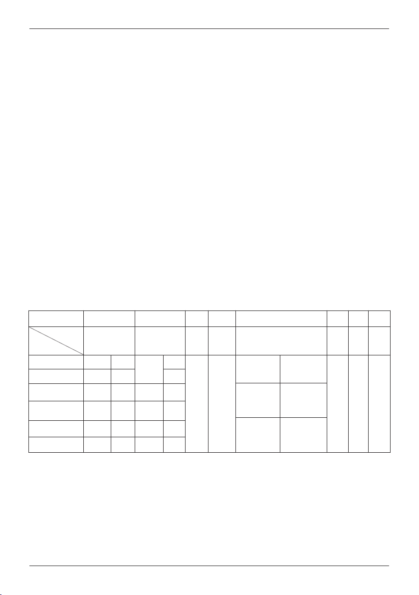
Overview
Model Operating mode
ISI30.010AX01
ISI30.012AX01
ISI30.013AX01
ISI31.010AX01
ISI31.011AX01
ISI31.013AX01 AC/DC
ISI32.013AX01
ISI33.010AX01
ISI33.011AX01
Table 1
Count
Cnt.Dir/Up.Dn
Up.Dn
Cnt.Dir
Quad/Quad2
Counting inputs
INP A
00 ... 0,7 V DC
04 ... 30 V DC
10 ... 260 V AC/DC AC/DC 30 Hz
00 ... 0,7 V DC
04 ... 30 V DC
10 ... 260 V AC/DC
10 ... 260 V AC/DC
00 ... 0,7 V DC
04 ... 30 V DC
NPN 7 kHz
PNP
NPN
PNP
AC/DC
NPN
PNP
Options: x = A: no backlight
12 kHz
7 kHz
12 kHz
30
Hz
30 Hz
3 kHz
6 kHz
INP B
00 ... 0,7 V DC
00 ... 0,7 V DC
10 ... 260 V AC/DC
00 ... 0,7 V DC
04 ... 30 V DC
10 ... 260 V AC/DC
10 ... 260 V AC/DC
00 ... 0,7 V DC
04 ... 30 V DC
x = B: with backlight
NPN 30 Hz
NPN
AC/DC
0–
NPN
PNP
12 kHz
30 Hz
AC/DC
30 Hz
AC/DC
NPN
PNP
7 kHz
3 kHz
6 kHz
DC input modes:
Count: Fast and slow counting inputs
INP A: Fast counting input
INP B: Slow counting input
Cnt.Dir: Counting and counting direction input
INP A: Counting input
INP B: Counting direction input
Up.Dn: Differential counting input
INP A: Adding counting input
INP B: Subtracting counting input
Quad: Phase discriminator input
INP A: 0° counting input
INP B: 90° counting input
Quad2: Phase discriminator input with
pulse doubling
INP A: 0° counting input
INP B: 90° counting input
Each edge of INP A is counted.
8 www.baumer.com
AC input modes:
Count: Counting and reset inputs
Cnt.Dir: Counting and counting direction input
Up.Dn: Differential counting input
INP A: AC/DC counting input
INP B: AC/DC reset input
INP A: AC/DC counting direction input
INP B: AC/DC counting input
INP A: AC/DC subtracting counting input
INP B: AC/DC adding counting input.
Page 9

Main technical features:
ISI30, ISI31, ISI32, ISI33
Display: LCD, 8 decades, height of the figures 8 mm.
isplay range: -9999999 ... 99999999
D
ith leading zeros suppression.
w
Overflow: In case of a display range overflow, the
ounter starts again from 0, but without
c
removing the leading zeros and activating
ll decimal points.
a
n case of a display range underflow, the
I
counter starts again from 0 and displays
he minus sign, without removing the lead-
t
ng zeros and activating all decimal points.
i
Keys: Electrical locking of the reset key
Housing: Panel mounting, 48 x 24 mm
according to DIN 43 700, RAL 7021
+0,3
Panel cut-out: 22,2
x 45
+0,6
mm
Mounting depth: approximately 48 mm
Weight: approximately 50 g
Protection level: IP65 on the front side
Connection: Screw terminals, RM 5.00, 8 poles
Rated cross-section: max.: 1 x 1,5 mm
2
2 x 0,75 mm
AWG 26-14
onnection diameter:
C
,4 ... 2,3 mm single-wire
0
AWG 28-12
EMC: Interference emissions EN55011 Class B
nterference resistance EN 61000-6-2
I
Device safety:
Design to: EN61010 Part 1
Protection Class: 2
pplication area: Soiling Level 2
A
ow Voltage Directive (for the AC models):
L
EN 61010 Part 1 ; overvoltage category 2,
contamination level 2
Power supply: Non-replaceable lithium battery
(lifetime approximately, 8 years at 20°C)
Working temperature:
–10 ... +55 °C, relative humidity < 85%,
without condensation
Operating temperature:
–10 ... +60 °C
Storage temperature:
2
–20 ... +70°C
Altitude: to 2000 m
Backlighting: external electrical source
(24 V DC ±20 %, 50 mA)
Input specification, pin assignment and adjustable operating modes (DC versions).
A control input (screw terminal 5) allows adjusting the operating mode.
Screw terminal Nr. 1
Designation
INP A
Nr. 2
INP B Reset
Model
NPN
PNP
NPN
PNP
NPN
PNP
30 Hz
7 kHz
12 kHz
3 kHz
6 kHz
ISI30.010AX01
ISI30.012AX01
ISI31.010AX01
ISI31.011AX01
ISI33.010AX01
ISI33.011AX01
7 kHz
12 kHz
7 kHz
12 kHz
3 kHz
6 kHz
Table 2
NPN
NPN
NPN
PNP
NPN
PNP
Nr. 3
Nr. 4 Nr. 5 Nr. 6 Nr. 7
Control inputs for operating
Reset
Enable
NPN reset input
with GND, key free..
NPN reset key locking input, Contact
mode (Mode)
not active
=
adding
not active
=
Cnt.Dr Mode
not active
=
Quad Mode
contact with
GND =
subtracting
contact with
GND =
Up.Dn Mode
contact with
GND =
Quad2 Mode
GND
english
Nr. 8
BL
BL
+
–
GND = 0 V DC
Backlighting (–)
Backlighting (+)
Screw terminals 1 and 2:
Function and max. frequences (Pulse/Pause 1:1)
see Table 2
NPN : active for negative edge
Input resistance: approximately 1 MOhm
Low level: 0 ... 0,7 V DC
High level: 3 ... 30 V DC
PNP : active for positive edge
Input resistance: approximately. 100 kOhm
Low level: 0 .. 0,7 V DC
High level: 4 .. 30 V DC
www.baumer.com 9
Page 10

ISI30, ISI31, ISI32, ISI33
Screw terminal 3:
eset input, active for negative edge Contact input / Open
R
Collector NPN (switching at 0 V DC)
Low level: 0 ... 0,7 V DC
High level: 3 ... 30 V DC
in. pulse duration: 50 ms
M
nput resistance: approximately 2,2 MOhm
I
crew terminal 5:
S
perating mode switch (Mode) Contact input / Open Collector
O
NPN (switching at 0 V DC)
Low level: 0 ... 0,7 V DC
igh level: 3 ... 5 V DC
H
Input resistance: approximately 2,2 MOhm
Function: see Table 2
Input specification and pin assignment (AC-version)
Common
AC/DC
Common connec-
tion for INP A and
No. 3
INP B AC/DC
reset
adding
INP B
counting
Screw terminal No. 1
Designation
Model
ISI30.013AX01
ISI31.013AX01
ISI32.013AX01
Table 3
Screw terminals 1 and 3:
Function: see Table 3
Optocoupler input 10 ... 260 V AC/V DC
galvanic isolation, active for high signal
Min. pulse duration: 16 ms
Max frequency: approximately 30 Hz
Low level: 0 ... 2 V AC/V DC
High level: 10 ... 260 V AC/V DC
Input resistance: approximately 160 kOhm
Screw terminal 2:
Common AC/DC, common connection for the optocoupler inputs
(screw terminals 1 and 3).
Screw terminal 4:
Electrical locking of the reset key Contact input / Open
Collector NPN (switching at 0 V DC)
Low level: 0 ... 0,7 V DC
High level: 3 ... 5 V DC
Input resistance: approximately 2,2 MOhm
Input not active: Reset key locked
Input in contact with GND:
AC/DC
counting
subtracting
counting
direction
Reset key unlocked
No. 2
INP A
Screw terminal 4:
lectrical locking of the reset key Contact input / Open Collector
E
NPN (switching at 0 V DC)
Low level: 0 ... 0,7 V DC
High level: 3 ... 5 V DC
nput resistance: approximately. 2,2 MOhm
I
nput not active: Reset key locked
I
nput in contact
I
ith GND: Reset key unlocked
w
Screw terminal 6:
GND connection common for all inputs
Screw terminal 7:
(–) external power supply for the LCD backlight option
Screw terminal 8:
(+) external power supply for the LCD backlight option
(24 V DC ±20%, 50 mA)
No. 4 No 5 No. 6
Reset Enable
NPN reset key lokking input, Contact
with GND. key free.
Screw terminal 5:
Function: see table 3, active for negative edge Contact input
/ Open Collector NPN (switching at 0 V DC)
Low level: 0 ... 0,7 V DC
High level: 3 ... 5 V DC
Min. pulse duration:
Input resistance: approximately 2,2 MOhm
Input high: - - Input low : Reset of the counter
Screw terminal 6:
Common GND connection for screw terminal 4 (reset key
locking input) and screw terminal 5 (reset input).
Screw terminal 7:
(–) external power supply for the backlight option
Screw terminal 8:
(+) external power supply for the backlight option
(24 V ±20%, 50 mA)
Reset GND BL
not connected
NPN reset input
0 V DC
GND =
50 ms
Dynamic resetting behaviour
No. 7
–
No. 8
Backlighting (–)
BL
+
Backlighting (+)
10 www.baumer.com
Page 11

ISI30, ISI31, ISI32, ISI33
Scope of delivery:
Digital dispay
Clamp
ront frame for screw mounting,
F
Panel cut-out 50 x 25 mm
Front frame for clamp mounting,
anel cut-out 50 x 25 mm
P
Seal
Operating instructions
Note:
This product includes a lithium battery. Do not open
it by force, do not throw it in the fire. Avoid temper-
tures below –20 °C and above 70 °C!
ou can send us back the complete devices after use. If you can
Y
emove the batteries according to the state of the art, you can
r
also bring them to a local collection point or to a retailer collecting batteries.
Specific provisions for returning lithium batteries:
Avoid short-circuits! For that purpose, protect the poles with isolating tape. The poles of the lithium battery shall not come in contact with metallic objects, neither by accident nor intentionally!
Batteries containing pollutants are marked with a symbol representing a crossed-out garbage can and the chemical symbol of
the heavy metal that determines their classification as containing pollutants. Thank you for your help!
a
his device contains a lithium battery. In compliance
T
with the battery directive, we inform you that:
Batteries must not be discarded in the household
aste, but the law obliges you to bring them to the
w
collection point specifically provided for that purpose.
english
www.baumer.com 11
Page 12

ISI30, ISI31, ISI32, ISI33
!
!
Instructions d’utilisation
Compteurs à affichage LCD
isiLine 30/31/32/33
Description
es compteurs à affichage isiLine sont alimentés par batterie. Ils
L
sont commandés par impulsions de contact ou de tension. Ils
euvent s'utiliser dans diverses applications, comme par exem-
p
le la totalisation, le comptage de pièces, la détection de posi-
p
ions, le comptage différentiel, etc.. Les différents modèles munis
t
de types d'entrées spécifiques peuvent en outre, grâce à des
modes opératoires ajustables, être étendus et réglés pour pratiquement toutes les applications.
1.1 Introduction
1.2 Instructions de sécurité et avertissements
1.3 Utilisation conforme
Cet appareil trouve son application dans les process et les commandes industriels dans les domaines des chaînes de fabrication
des industries du métal, du bois, des matières plastiques, du
papier, du verre, des textiles, etc., avec un degré de salissure de
2. Les surtensions aux bornes à visser de l’appareil doivent être
limitées à la valeur de la catégorie de surtension II. L’appareil ne
convient pas pour des zones présentant des risques d’explosion,
ni pour les domaines d’utilisation exclus par la norme EN 61010
Partie 1. L’appareil ne peut être utilisé que comme appareil
encastré et à l’intérieur. Cependant, dans certaines conditions,
une utilisation à l’extérieur est également admise. Il peut être
mis en ouvre jusqu’à une altitude de 2.000 m. Toute autre utilisation est considérée comme non conforme à sa destination.
Si l’appareil est mis en ouvre pour la surveillance de machines
ou de process où, en cas de panne ou d’une erreur de manipulation de l’appareil, peuvent apparaître des risques de dommages
à la machine ou d’accidents pour les opérateurs, il vous appartient de prendre les mesures de sécurité appropriées.
1.4 Montage encastré
Lisez attentivement ces instructions d’utilisation
avant le montage et la mise en service. Pour votre
propre sécurité, ainsi que pour la sécurité de fonctionnement, respectez tous les avertissements et indications. Une utilisation de l’appareil non conforme à
ces instructions peut affecter la protection prévue.
N’utilisez cet appareil que s’il est techniquement en
parfait état, de manière conforme à sa destination,
en tenant compte de la sécurité et des risques, et
dans le respect des instructions d’utilisation et de ce
supplément. Il faut également respecter les normes
de sécurité en vigueur pour les installations électriques.
Montez l’appareil loin de toute source de chaleur et
évitez tout contact direct avec des liquides corrosifs,
de la vapeur chaude ou des substances similaires.
Lors de l’installation, veiller à assurer un refroidissement suffisant de l’appareil.
1.5 Instructions de montage
– Retirer le cadre de fixation de l’appareil.
– Introduire l’appareil par l’avant dans la découpe d’encastre-
ent du panneau et veiller à ce que le joint du cadre avant
m
oit correctement en place.
s
– Glisser par l’arrière le cadre de fixation sur le boîtier jusqu’à ce
ue les étriers élastiques soient comprimés et que les ergots
q
haut et bas soient encliquetés.
1.6 Installation électrique
et appareil est alimenté par une batterie interne.
C
– Afin de respecter les prescriptions de protection
ontre les incendies, il ne faut pas dépasser un cou-
c
rant de 8 A/150 VA sur le compteur en cas de
défaut !
– Il est interdit de câbler les bornes inutilisées de
l’appareil.
– Respecter impérativement l’affectation des broches
des connecteurs, ainsi que les valeurs maximales
admissibles.
– Une installation CEM conforme est la condition
préalable à la conformité CE.
1.7 Indications quant à la résistance
aux perturbations
Tous les raccordements sont protégés contre les perturbations
extérieures. Choisir le lieu d’utilisation de sorte que des perturbations inductives ou capacitives ne puissent pas affecter l’appareil ou les câbles raccordés à celui-ci ! Un tracé de câblage
approprié permet de réduire les perturbations (dues p. ex. à des
alimentations à commutation, des moteurs, des variateurs ou
des contacteurs cyclés).
1.8 Mesures à prendre :
– N’utiliser que du câble blindé pour les lignes de signal et de
commande.
– Raccorder le blindage des deux côtés.
– Section de la tresse des conducteurs 0,14 mm² min.
– La liaison du blindage à la compensation de potentiel doit être
aussi courte que possible et s’effectuer sur une grande surface
(basse impédance).
– Ne relier les blindages au panneau que si celui-ci est aussi mis
à la terre.
– En cas de problèmes dus à une boucle de terre, il faut raccor-
der le blindage du côté réception avec une basse impédance
et, du côté émission, à la terre de référence au moyen d’un
condensateur d’environ 100nF.
– L’appareil doit être encastré aussi loin que possible de lignes
soumises à des perturbations.
– Eviter de poser les conducteurs en parallèle avec des conduc-
teurs d’énergie.
– Les conducteurs et les isolations de ceux-ci doivent correspon-
dre aux plages de température, de tension et de puissance pré-
vues. Les normes du pays d’installation s’appliquent.
Exécutions DC :
Utiliser des fils blindés pour les entrées de comptage et de commande afin d’obtenir la résistance CEM maximale ou connecter
au GND (0 V) les entrées de comptage non utilisées.
12 www.baumer.com
Page 13

ISI30, ISI31, ISI32, ISI33
Exécutions AC :
tiliser des fils blindés pour les entrées de comptage et de com-
U
mande afin d’obtenir la résistance CEM maximale.
1.9 Mise en route
– L’appareil est-il bien réglé et programmé (fonction ; fréquence
e comptage max. pour les compteurs) ?
d
1.10 Possibilités de défauts et leurs causes
mpossible d’utiliser les touches :
I
Entrée de verrouillage des touches activée
-
e compteur ne compte pas :
L
- Entrée de comptage mal raccordée ou raccordée à l’envers
- Réglage d’un signal d’entrée erroné pour le générateur d’impulsions
- Polarité (NPN/PNP) inversée
- Pas de raccordement à la masse entre le générateur d’impulsions et le compteur
- Dépassement de la fréquence de comptage maximale
Sommaire
Modèle
ISI30.010AX01
ISI30.012AX01
ISI30.013AX01
ISI31.010AX01
ISI31.011AX01
ISI31.013AX01
ISI32.013AX01
ISI33.010AX01
ISI33.011AX01
Tableau 1
Mode opératoire
Count
Cnt.Dir/Up.Dn
Up.Dn
Cnt.Dir
Quad/Quad2
Entrées de comptage
INP A INP B
00 ... 0,7 V DC
04 ... 30 V DC
10 ... 260 V AC/DC
00 ... 0,7 V DC
04 ... 30 V DC
10 ... 260 V AC/DC
10 ... 260 V AC/DC
00 ... 0,7 V DC
04 ... 30 V DC
- Les niveaux des signaux n’atteignent pas le seuil de commutaion du compteur
t
Si votre appareil ne fonctionne toujours pas, adressez-vous à
votre agent local compétent, ou appelez-nous directement pour
n conseil technique.
u
n cas de retour, joignez une brève description du défaut, de la
E
rogrammation et du schéma de branchement, afin de nous per-
p
ettre de reproduire un éventuel défaut et d’assurer une répara-
m
tion de votre appareil aussi rapide que possible.
07 kHz 00 ... 0,7 V DC NPN 30 Hz
NPN
07 kHz
12 kHz
30 Hz
30 Hz
03 kHz
06 kHz
00 ... 0,7 V DC
10 ... 260 V AC/DC
00 ... 0,7 V DC
04 ... 30 V DC
10 ... 260 V AC/DC
10 ... 260 V AC/DC
00 ... 0,7 V DC
04 ... 30 V DC
x = B: rétroéclairé
NPN
AC/DC
NPN
PNP
AC/DC
AC/DC
NPN
PNP
0–
07 kHz
12 kHz
30 Hz
30 Hz
03 kHz
06 kHz
PNP 12 kHz
AC/DC 30 Hz
NPN
PNP
AC/DC
AC/DC
NPN
PNP
Options : x = A: non rétroéclairé
s
i
a
ç
n
a
r
f
Type d’entrée CC :
Count : Entrée de comptage rapide et lente
Cnt.Dir :
Up.Dn : Entrée de comptage différentiel
Quad : Entrée de discriminateur de phase
Quad2 : Entrée de discriminateur de phase avec
INP A: Entrée de comptage rapide
INP B: Entrée de comptage lente
Entrée de comptage et de sens de comptage
INP A: Entrée de comptage
INP B: Entrée de sens de comptage
INP A: Entrée de comptage additionnante
INP B: Entrée de comptage soustrayante
INP A: Entrée de comptage 0°
INP B: Entrée de comptage 90°
doublement des impulsions
INP A: Entrée de comptage 0°
INP B: Entrée de comptage 90°
Chaque front de INP A est compté.
Type d’entrée CA :
Count : Entrée de comptage et de remise à zéro
Cnt.Dir :
Up.Dn : Entrée de comptage différentiel
www.baumer.com 13
INP A: Entrée de comptage AC/DC
INP B: Entrée de remise à zéro AC/DC
Entrée de comptage et de sens de comptage
INP A:
Entrée de sens de comptage
INP B: Entrée de comptage AC/DC
INP A: Entrée de comptage soustrayante
AC/DC
INP B: Entrée de comptage additionnante
AC/DC.
AC/DC
Page 14
ISI30, ISI31, ISI32, ISI33
Caractéristiques techniques générales :
Affichage : LCD, 8 décades, hauteur des chiffres 8 mm.
lage d’affichage :
P
9999999 ... 99999999
avec suppression des zéros de tête.
épassement :
D
En cas de dépassement de la plage
’affichage, le compteur repart de 0, mais
d
ans suppression des zéros de tête et en
s
activant tous les points décimaux.
n cas de dépassement de la plage d’affi-
E
hage par le bas, le compteur repart de 0,
c
mais en affichant le signe moins, sans
suppression des zéros de tête et en activant
tous les points décimaux.
Touches : Verrouillage électrique de la touche de
remise à zéro
Boîtier : Montage dans tableau, 48 x 24 mm
suivant DIN 43 700, RAL 7021
Découpe d’encastrement :
22,2
0,3
0,6
+
+
x 45
mm
Profondeur de montage :
env. 48 mm
Poids : env. 50 g
Indice de protection :
IP65 sur la face avant
Raccordements : Bornes à vis, RM 5.00, 8 bornes
Section nominale:
max.: 1 x 1,5 mm
2 x 0,75 mm
WG 26-14
EM : Emissions parasites EN55011 Classe B
C
A
Résistance aux parasites EN 61000-6-2
écurité de l’appareil
S
onception selon : EN61010 Partie 1
C
Classe de protection :
Classe de protection 2
Domaine d’utilisation :
Degré de salissure 2
Alimentation : Batterie au lithium non remplaçable
(durée de vie env. 8 ans à 20°C)
Température de travail :
–10 ... +55 °C, humidité relative < 85%,
sans condensation
Température de fonctionnement:
–10 ... +60 °C
Température de stockage :
–20 ... +70 °C
Altitude : jusqu’à 2000 m
Rrétroéclairage: source électrique extérieure
(24 V DC ±20 %, 50 mA)
Entrées, Raccordement et modes opératoires ajustables (exécutions CC).
Une entrée de commande (borne à vis 5) permet l'ajustage du mode opératoire.
Borne à vis Nr. 1 Nr. 2 Nr. 3 Nr. 4 Nr. 5 Nr. 6 Nr. 7
Désignation
Modèle
ISI30.010AX01
ISI30.012AX01
ISI31.010AX01
ISI31.011AX01
ISI33.010AX01
ISI33.011AX01
Tableau 2
INP A INP B Reset Reset
7 kHz
NPN
30 Hz NPN
PNP
12 kHz
7 kHz
12 kHz
3 kHz
6 kHz
NPN
PNP
NPN
PNP
7 kHz
12 kHz
3 kHz
6 kHz
NPN
NPN
PNP
NPN
PNP
Enable
Mode GND BL
non activée
=
additionnant
non activée
=
Mode Cnt.Dr
touche libérée..
non activée
Entrée de remiseà zéro NPN
Entrée de verrouillage de la touche de
remise à zéro NPN. Contact avec GND,
=
Mode Quad
contact avec
GND=
soustrayant
contact avec
GND =
Mode Up.Dn
contact avec
GND =
Mode Quad2
GND = 0 V DC
2
2
Nr. 8
BL
–
+
Rétroéclairage (–)
Rétroéclairage (+)
Bornes à vis 1 et 2:
Fonction et fréquences max. : voir le Tableau 2
(Impulsion/Pause: 1:1)
NPN : active pour front négatif
Résistance d’entrée : env. 1 MOhm
Niveau Bas : 0 ... 0,7 V DC
Niveau Haut : 3 ... 30 V DC
PNP : active pour front positif
Résistance d’entrée : env. 100 kOhm
Niveau Bas : 0 ... 0,7 V DC
Niveau Haut : 4 ... 30 V DC
14 www.baumer.com
Page 15

Borne à vis 3 :
ntrée de remise à zéro, active pour flanc négatif Entrée de
E
contact / Open Collector NPN (commutation à 0 V DC)
Niveau Bas : 0 ... 0,7 V DC
Niveau Haut : 3 ... 30 V DC
urée d’impulsion min. : 50 ms
D
ésistance d’entrée : env. 2,2 MOhm
R
orne à vis 5 :
B
hangement de mode opératoire (Mode) Entrée de contact /
C
Open Collector NPN (commutation à 0 V DC)
Niveau Bas : 0 ... 0,7 V DC
iveau Haut : 3 ... 5 V DC
N
Résistance d’entrée : env. 2,2 MOhm
Fonction : voir le Tableau 2
ISI30, ISI31, ISI32, ISI33
orne à vis 4 :
B
Verrouillage électrique de la touche de remise à zéro
Entrée de contact / Open Collector NPN
(commutation à 0 V DC)
iveau Bas : 0 ... 0,7 V DC
N
Niveau Haut : 3 ... 5 V DC
ésistance d’entrée : env. 2,2 MOhm
R
Entrée non activée : Touche de RAZ verrouillée
Entrée en contact
vec GND: Touche de RAZ déverrouillée
a
Borne à vis 6 :
accordement GND commun à toutes les entrées
R
Borne à vis 7 :
(–) alimentation extérieure pour l’option LCD rétroéclairé
Borne à vis 8 :
(+)
alimentation extérieure pour l’option LCD rétroéclairé
DC
±
20 %, 50 mA)
(24 V
Raccordement (exécutions AC).
Borne à vis
Désignation
Modèle
ISI30.013AX01
ISI31.013AX01
ISI32.013AX01
Tableau 3
Bornes à vis 1 et 3 :
Fonction : voir le Tableau 3 Entrée optocoupleur 10 ... 260 V
AC/V DC découplage galvanique, actif pour signal Haut
Durée d’impulsion min. :
Fréquence max. : env. 30 Hz
Niveau Bas : 0 ... 2 V AC/V DC
Niveau Haut : 10 ... 260 V AC/V DC
Résistance d’entrée : env. 160 kOhm
Borne à vis 2 :
Commun CA/CC, raccordement commun pour les
entrées optocoupleur (borne à vis 1 et borne à vis 3).
Borne à vis 4 :
Verrouillage électrique de la touche de remise à zéro
Entrée de contact / Open Collector NPN
(commutation à 0 V DC)
Niveau Bas : 0 ... 0,7 V DC
Niveau Haut : 3 ... 5 V DC
Résistance d’entrée :
Entrée non activée :Touche de remise à zéro verrouillée
Entrée en contact avec GND :
N° 1
AC/DC
comptage
soustrayant
sens de
comptage
16 ms
env. 2,2 MOhm
Touche de remise à zéro déverrouillée
INP A
N° 2 N° 3
AC/DC
raccordement com-
INP B
mun pour INP A et
INP B AC/DC
remise à zéro
additionnant
comptage
Common
N° 4 N° 5 N° 6
Reset Enable
Entrée de verrouillage
de la touche de remise à zéro NPN.
Contact avec GND.
touche libérée.
Borne à vis 5 :
Fonction : voir le tableau 3, actif pour front négatif
Entrée de contact / Open Collector NPN
(commutation à 0 V DC)
Niveau Bas : 0 ... 0,7 V DC
Niveau Haut : 3 ... 5 V DC
Durée d’impulsion min. :
Résistance d’entrée :
Entrée Haute : - - Entrée Basse : Remise àzéro du compteur
Borne à vis 6 :
Raccordement GND commun pour la borne 4
(entrée de verrouillage de la touche de remise à zéro) et la
borne 5 (entrée de remise à zéro).
Borne à vis 7 :
(–) alimentation extérieure pour l’option
rétroéclairage
Borne à vis 8 :
(+) alimentation extérieure pour l’option
rétroéclairage
Reset GND BL–BL
libre
Entrée de remise
à zéro NPN
50 ms
env. 2,2 MOhm
Comportement dynamique
à la remise à zéro
(24 V ±20%, 50 mA)
N° 7
0 V DC
GND =
Rétroéclairage (–)
N° 8
s
i
a
ç
n
a
r
+
Rétroéclairage (+)
f
www.baumer.com 15
Page 16

ISI30, ISI31, ISI32, ISI33
Etendue de la livraison :
Compteur
Etrier de montage
adre avant pour fixation par vis,
C
Découpe d’encastrement 50 x 25 mm
Cadre avant pour fixation par étrier,
écoupe d’encastrement 50 x 25 mm
D
Joint
Instructions d’utilisation
Nota :
Ce produit comporte une batterie au lithium. Ne
pas l’ouvrir de force, ne pas le jeter au feu. Eviter
es températures inférieures à –20 °C et supérieu-
Vous pouvez nous retourner les appareils complets usagés. Si
vous êtes en mesure de retirer les piles dans les règles de l’art,
vous pouvez aussi porter celles-ci dans une déchetterie communale ou les déposer dans un commerce qui récupère les piles.
Dispositions spécifiques pour le retour de piles au lithium :
Evitez les courts-circuits ! Pour cela, protégez les bornes de la
pile à l’aide de ruban adhésif isolant. Ne mettez pas les bornes
de la pile au lithium en contact avec des objets métalliques, ni
involontairement ni volontairement !
Les piles contenant des substances polluantes sont indiquées par
un symbole représentant une poubelle barrée et le symbole chimique du métal lourd qui détermine leur classification en tant
que polluants. Merci de votre contribution !
d
es à 70 °C !
r
et appareil contient une pile au lithium.
C
Conformément aux dispositions sur la récupération
et le recyclage des piles, nous vous informons que :
es piles ne doivent en aucun cas être jetées avec
L
es ordures ménagères. La loi vous impose de les
l
rapporter aux points de collecte spécifiquement prévus à cet effet.
16 www.baumer.com
Page 17

Anschlussbilder/Connections/Schémas de branchement:
max.5VDCmax.30VDC
(-)BL
(+)BL
INP A
I
NP B
Reset
Mode
GND
24VDC±20%,50mA
1
2
3
4
5
6
7
8
R
eset
E
nable
(-)BL
(+)BL
INP A
I
NP B
R
eset
Mode
GND
1
2
3
4
5
6
7
8
R
eset
Enable
max.5VDCmax.30VDC
24VDC±20%,50mA
(-)BL
(+)BL
INP A
INP B
Reset
Mode
GND
1
2
3
4
5
6
7
8
Reset
Enable
max.5VDCmax.30VDC
24VDC±20%,50mA
max.5VDC
10..260
10..260
VAC /VD C
VAC /VD C
(-)BL
(+)BL
INP A
INP B
Common
AC/DC
GND
n.c.
1
3
2
4
5
6
7
8
Reset
Enable
24VDC±20%,50mA
max.5VDC
(-)BL
(+)BL
INP A
INP B
GND
1
3
2
4
5
6
7
8
Reset
Reset
Enable
10..260
10..260
VAC /VD C
VAC /VD C
Common
AC/DC
24VDC±20%,50mA
ISI30, ISI31, ISI32, ISI33
DC-Typ:
ISI30.010AX01
ISI31.010AX01
ISI33.010AX01
DC-Typ:
ISI30.012AX01
DC-Typ:
ISI31.011AX01
SI33.011AX01
I
AC-Typ:
ISI30.013AX01
s
i
a
ç
n
a
r
f
AC-Typ:
ISI31.013AX01
ISI32.013AX01
BL = Hinterleuchtung/backlight/rétroéclairage
www.baumer.com 17
Page 18

ISI30, ISI31, ISI32, ISI33
Abmessungen/Dimensions/Dimensions:
Schalttafelausschnitt/Panel cut-
ut/Découpe d’encastrement :
o
Schalttafelausschnitt/Panel cut-out/Découpe
d’encastrement :
1
Senkung Af3, DIN 74/Countersinking Af3, DIN 74/Fraisure Af3, DIN 74
18 www.baumer.com
Page 19

Page 20

Baumer IVO GmbH & Co. KG
Dauchinger Strasse 58–62
DE-78 056 Villingen-Schwenningen
Phone +49 (0)7720 942 -0
Fax +49 (0)7720 942-900
info.de@baumerivo.com
R.60339.9408
Sous réserve modifications et d‘erreur dans la technique et le design.
Subject to modification in technic & design.
Irrtum sowie Änderungen in Technik und Design vorbehalten.
www.baumer.com
 Loading...