

Page 1
EN
INSTALLATION INSTRUCTIONS MODBUS TEDM - ETTNM
Modbus Communication - Overview
The TEDM pressostat and the ETTNM thermostat have a serial RS485 port and use
the Modbus RTU communication protocol.
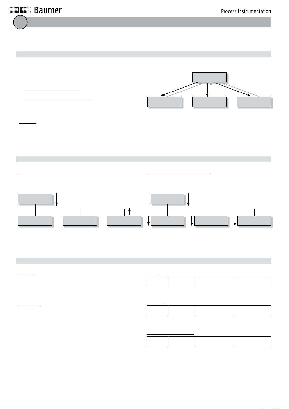
The Modbus protocol is a dialog protocol based on a hierarchical structure consisting
of a master and several slave devices. It supports reading the pressure level (TEDM)
or the temperature (ETTNM), as well as the status of each coil (open or closed).
Communication from master to 1 slave: the master sends a query and waits for a
response.
Communication from master to all slave devices: the master sends a message to all
slaves currently on the network, they execute the command in the message without
sending a reply.
Two slave devices cannot talk to each other.
Addressing
The devices on the bus are identified by addresses assigned by the user. The address
of each subscriber is not related to its physical location.
Modbus communication - Principles
Master
Slave device A Slave device B Slave device C
E.g.: slave device = TEDM / ETTNM ...
These addresses range from 1 to 247 and do not have to be assigned sequentially.
There cannot be two slave devices with the same address.
Factory default address TEDM / ETTNM: 246.
Communication from master to a single slave
The master queries the slave over the network and waits for a response from that
slave.
Master
Slave device A Slave device B Slave device C
Query
Response
Frame for query/response
The query
It contains a function code telling the slave being queried what type of action is
required.
The data contains any additional information the slave may need to execute the function.
The checksum allows the slave to check the integrity of the query content.
The response
If an error occurs, the function code is changed to indicate that the reply is an exception response (MSB*=0: no error; MSB=1: error).
The data then includes a code (exception code) indicating the type of error.
Exception code:
01 Illegal function (function code error)
02 Error in the register address or coil address
08 Transmission error (after checking the CRC or the synchronization)
*MSB : Most Significant Bit
Communication from master to all slaves
Communication from the master to all slave devices: the master sends a message
to all slaves currently on the network, they execute the command in the message
without sending a reply.
Master
Slave device A Slave device B Slave device C
Command
Query:
Device #
of slave
1 byte 1 byte n bytes 2 bytes
Function code
+ error bit
Specific information
about the command
Checksum
Response:
Device #
of slave
1 byte 1 byte n bytes 2 bytes
Function code
+ error bit
Transmitted data Checksum
Response in case of an error:
Device #
of slave
1 byte 1 byte 1 byte 2 bytes
Function code
+ error bit
Exception code Checksum
Baumer Bourdon-Haenni S.A.S. · 125, rue de la Marre · B.P. 70214 · 41103 Vendôme Cedex · France
Tel. +33 (0)2 54 73 74 75 · Fax France +33 (0)2 54 73 74 74 · Fax Export +33 (0)2 54 73 74 73
sales.fr@baumerprocess.com · www.baumer.com
320124 ind a 11/2012
Page 2
General format of a frame
Two types of encoding may be used to communicate over a Modbus network:
ASCII - each byte making up the frame consists of 2 ASCII characters
RTU (Remote terminal unit) - each byte making up the frame consists of 2 hexa-
decimal characters (2 x 4 bits).
ASCII mode allows having gaps of more than one second between the different characters without causing errors, while the RTU mode allows more data to be passed at
the same transmission speed.
The TEDM and ETTNM use RTU coding to communicate over the Modbus network.
ASCII frame:
START Address Function Data LRC END
1 chara 2 charas 2 charas n charas 2 charas 2 charas
RTU frame:
START Address Function Data CRC 16 END
1 byte 1 byte 1 byte n bytes 2 bytes Silence
RTU Type
The maximum data size is 256 bytes. All the information contained in the message is written as hexadecimal.
The master instructs a slave. The function code tells the slave what type of action to
carry out. For example: read the register, function code 03 hex.
The data field is coded for n words in hexadecimal from 00 to FF, or for n bytes.
Depending on the function code, the data field may hold different additional information allowing the slave to interpret the message.
If RTU coding is used, the checksum CRC (Cyclical Redundancy Check) allows
the integrity of the received data to be checked. The CRC contains a value which is
encoded as 16 bits..
The slave sends its response; it places its own address in the address field so that
the master can identify it.
For a normal response, the slave uses the same function code as the one in the
message sent by the master.
The checksum field contains a value which is encoded as 16 bits. This value is the
result of a CRC calculation using the message.
Data carrier
Each byte making up a message is transmitted as follows in RTU mode:
No parity check START Bit 0 Bit 1 Bit 2 Bit 3 Bit 4 Bit 5 Bit 6 Bit 7 STOP STOP
With parity check START Bit 0 Bit 1 Bit 2 Bit 3 Bit 4 Bit 5 Bit 6 Bit 7 Parity STOP
In the TEDM and ETTNM configuration menu it is possible to opt for parity
checking or not.
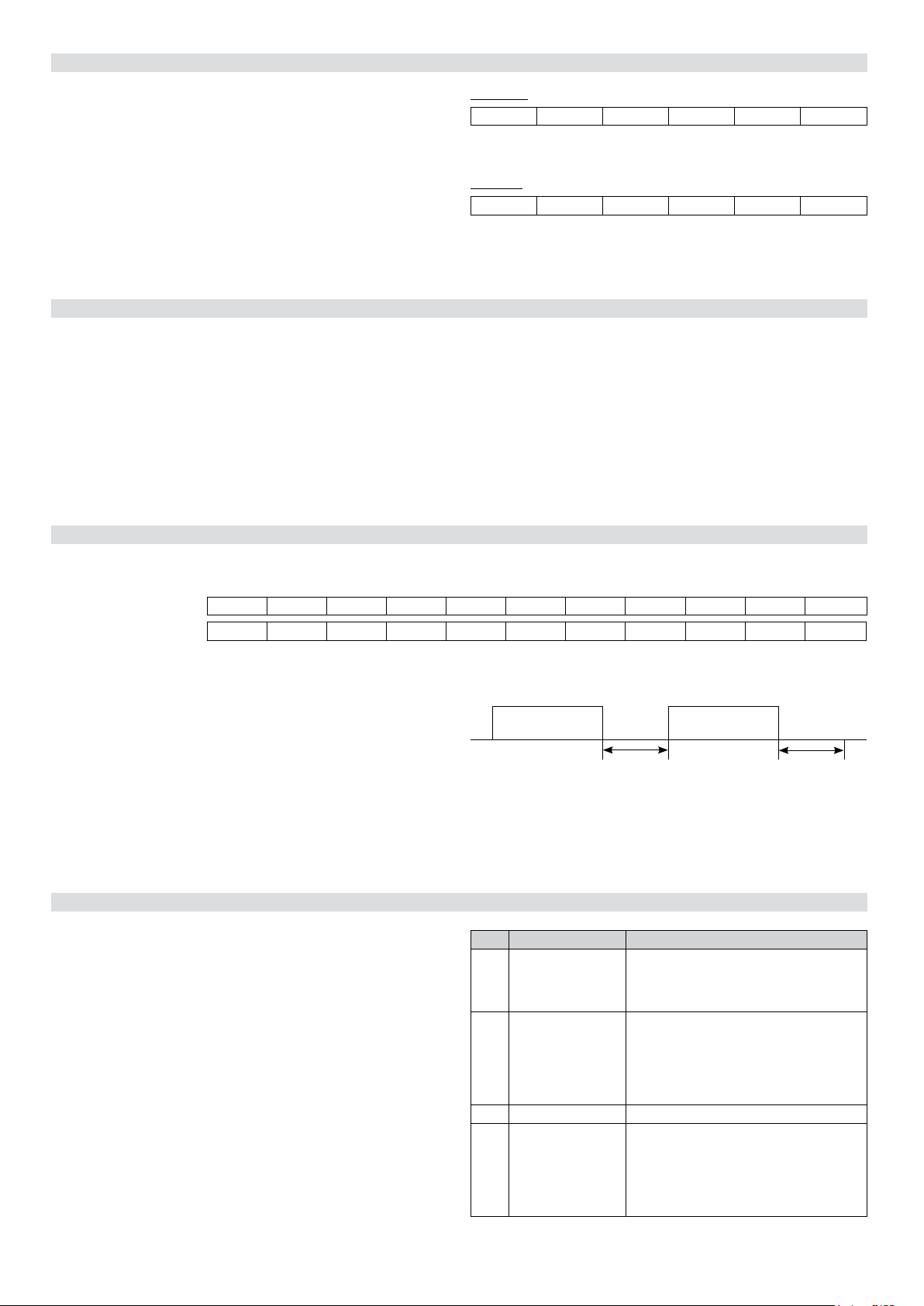
Before and after each message (frame), there must be a silence lasting a minimum
of 3.5 times the time needed to transmit a byte.
The whole message must be sent continuously. The maximum time between 2 bytes
must be less than 1.5 times the time required to transmit a byte.
Otherwise there is a transmission error.
The MODBUS protocol only defines the message structures and their exchange
mechanism.
If a parity check is used, you need to confirm the reference status: ‘even’ or ‘odd’.
Message from the
master
Minimum delay of 3.5 times the
time needed to transmit a byte
You can use any transmission interface, RS 232, RS 422 or RS 485, but the RS485
connector is the most widely used because it supports multipoints.
TEDM-ETTNM:
Data transmission speed: 9600 baud. Interface: RS485.
Message from the
slave
Minimum delay of 3.5 times the
time needed to transmit a byte
TEDM/ETTNM - Function codes
The TEDM and ETTNM use 4 function codes.
These function codes allow collection of:
- the value of the pressure reading (TEDM) or the temperature (ETTNM)
- the status of each coil (open or closed),
and writing of
- the status and setting of the coils
- the access code
- the address for the slave
Code Function Action
01 Read Coils Status Read the status of coils 1 and 2: open or closed
03 Read Holding Register Read the measured value. Pressure (TEDM) or
05 Write Single Coil
06 Write Single Register
Read the coil setting: Normally Open (NO) or
Normally Closed (NC)
Read the position of the decimal point (display)
Temperature (ETTNM)
Read the access code
Read the value of the high and low switching points
for each coil
Read the value of the timer for each coil
Write the coil’s configuration: NO or NC
Write the access code
Write the value of the high and low switching points
for each coil
Write the value of the timer for each coil
Write the slave’s address (TEDM or ETTNM)
320124 ind a 11/2012
Page 3

Transmission samples
Read Coil Status - function code 01
The master queries the TEDM/ETTNM about the coils’ status.
The start address for reading the coils is fixed and the number of coils is always 16. Coils are always addressed starting from zero: so
coils 1-16 are addressed as 0-15.
Sample command to read coils 16-01 of slave 59:
Field name Example
Slave Address 3B hex
Function 01 hex
Starting Address Hi 00 hex
Starting Address Lo 00 hex
Query
No. of Points Hi 00 hex
No. of Points Lo 10 hex
Error Check (CRC) —
Read Holding Register - function code 03
The master queries the TEDM/ETTNM on the value of the reading, the code, the setting of the high and low switching points of the timers for the coils.
The query indicates the register address to be read. Registers are always addressed starting from zero: so registers 1-11 are addressed as 0-10.
Sample response to the query:
Field name Example
Slave Address 3B hex
Function 01 hex
Byte Count 02 hex
Data (Coils 08-01) 21 hex
Response
Data (Coils 16-09) 00 hex
Error Check (CRC) —
The status of the coils (08-01) results in the byte value 21
hex, or 0010 0001 in binary, so coil 1 is active.
Coil 1 configured as NO and Coil 2 configured as NC.
Bit = 0: NC configuration. Bit = 1: NO configuration.
Addr.
Action
Coil
00 Status Coil 1
01 Status Coil 2
02
03
04 NO-NC 1
05 NO-NC 2
06
07
08 Position
09 of
10 decimal
11 point
12
13
14
15
Sample request to read register 1 (measured value) of slave 59:
Field name Example
Slave Address 3B hex
Function 03 hex
Starting Address Hi 00 hex
Starting Address Lo 00 hex
Query
No. of Points Hi 00 hex
No. of Points Lo 01 hex
Error Check (CRC) —
Write Single Coil - function code 05
This function code is used to remotely configure coils as NO or NC. The coils involved are 05 (NO) and 06 (NC) with addresses adr 04
and adr 05 respectively.
To configure a coil as NO, the value FF 00 hex is sent to the slave.
To configure a coil as NC, the value 00 00 hex is sent to the slave.
Sample request to set coil 05 of slave 59 to 1.
The master transmits the value FF 00:
Field name Example
Slave Address 3B hex
Function 05 hex
Starting Address Hi 00 hex
Starting Address Lo 04 hex
Query
No. of Points Hi FF hex
No. of Points Lo 00 hex
Error Check (CRC) —
Write Single Register - function code 06
This function code is used to remotely configure the access code*, the high and low switching points for the coils, the timer for the coils, the
address of the TEDM or ETTNM.
The query indicates the register address involved. The registers are always addressed starting from 1: registers 2-11 are addressed as 1-10.
Please note: the switching values, the access code and the slave address are inserted in the respective registers in hexadecimal.
Sample request to write the set point for slave 59:
Field name Example
Slave Address 3B hex
Function 06 hex
Starting Address Hi 00 hex
Starting Address Lo 02 hex
Query
No. of Points Hi 00 hex
No. of Points Lo 6E hex
Error Check (CRC) —
* access code for configuration from the front of the TEDM or ETTNM.
Sample response to the query:
Field name Example
Slave Address 3B hex
Function 03 hex
Byte Count 02 hex
Data Hi (Register 1) 0A hex
Response
Data Lo (Register 1) 2B hex
Error Check (CRC) —
For register 1: The content results in the value of two bytes
0A 2B hex or 2603 decimal.
The slave confirms the write action by sending back the
same message.
Sample response to the query:
Field name Example
Slave Address 3B hex
Function 05 hex
Starting Address Hi 00 hex
Starting Address Lo 04 hex
Response
No. of Points Hi FF hex
No. of Points Lo 00 hex
Error Check (CRC) —
Coil 1 is configured as NO.
Sample response to the query:
Field name Example
Slave Address 3B hex
Function 05 hex
Starting Address Hi 00 hex
Starting Address Lo 02 hex
Response
No. of Points Hi 00 hex
No. of Points Lo 6E hex
Error Check (CRC) —
The set point for coil 1 is set to 00 6E hex or 110 decimal.
Addr.
Action
Reg
00
Value measured
01 Code
02 Value HSP1
03 Value LSP1
04 Value HSP2
05 Value LSP2
06
07 Value TS1
08 Value TH1
09 Value TS2
10 Value TH2
Addr.
Action
Coil
00
01
02
03
04 NO-NC 1
05 NO-NC 2
06
07
08
09
10
11
12
13
14
15
Adr.
Action
Reg
00
01 Code
02 Value HSP1
03 Value LSP1
04 Value HSP2
05 Value LSP2
06 Slave addr.
07 Value TS1
08 Value TH1
09 Value TS2
10 Value TH2
For more information about the Modbus protocol go to: http://www.modbus.org/
320124 ind a 11/2012
Page 4

Baumer Bourdon-Haenni S.A.S. · 125, rue de la Marre · B.P. 70214 · 41103 Vendôme Cedex · France
Tel. +33 (0)2 54 73 74 75 · Fax France +33 (0)2 54 73 74 74 · Fax Export +33 (0)2 54 73 74 73
sales.fr@baumerprocess.com · www.baumer.com
320124 ind a 11/2012
 Loading...