

Page 1
Cleaning and maintenance
There is no need cleaning the pressure transmitter. However, in order to avoid any damage,
please do not direct high pressure cleaning “jets
of water” directly at the diaphragm. In particular,
never clean the diaphragm with tools or other
mechanical objects. Do not insert hard objects
into the pressure gauge opening.
Operation / procedure in case of
malfunction
The admissible range acc. to technical datasheet must be respected in any case.
In case of malfunction, please check the following points :
– Check the data on the label plate and compare
with the installed confi guration.
– Check wiring.
– Check the power supply and load.
– Check if the diaphragm is ok or damage.
– Check the possibilities of EMC infl uences.
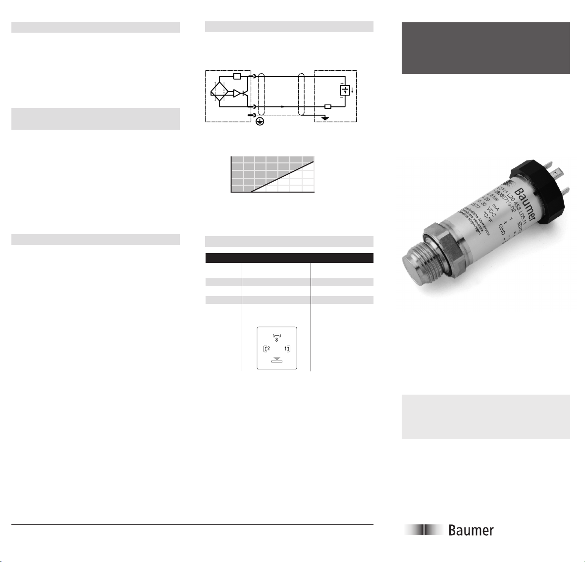
Connecting diagram
Electrical connection
For 4 … 20 mA current loop
a
b
I
A
d
Load RL + R
1500
Line
1200
900
+R
L
600
300
Load R
:
Line
Prohibited
zone
0
0 5 10 15 20 25 30 35
Supply voltage
Pressure Transmitter
ED 711
U
B
R
L
Repair
Please send the pressure transmitter (if possible with the original packing) to the nearest
representation.
Detailed information regarding the malfunction
helps us in obtaining a faster anal y sis.
www.baumerprocess.com Application Manual G45214.1
Design and specifi cations subject to change without notice
Pin assignment
Contact DIN 43650 plug
4…20 mA
a 1
b 2
c –
d GND
View
soldering
side
cable
socket
Installation and
Operating Instructions
E-2004-05-01
Page 2

Thank you for having chosen our product. These
instructions should allow you an easy installation. Please study this documentation carefully
and retain for further reference. Information
about the materials used and general technical
data can be obtained from the relevant technical
data sheet.
1. General points
This pressure transmitter is a precision measuring device. The highly sensitive diaphragm is
protected with a cap which should only be removed just prior to the installation. Take special
care to avoid abrasive media, solid bodies and
other mechanical damage (thumb-mark).
Please follow these instructions carefully so
that the pressure transmitter works perfectly.
The admissible storage temperature is –10 °C ...
+100 °C (dry air).
The pressure transmitter corresponds – under
the condition that the installation has been
properly effected – to the EMC standards EN
50081-1 and 2, as well as EN 50082-2 and EN
61326.
2. Installation / Removal
2.1 Pressure transmitter with thread
Screw the pressure transmitter in the corresponding threaded hole and tighten with the
following torque :
Pressure range (bar) Torque (Nm)
0,1 – 10 30
It is advisable to grease the threads lightly
with a molybdenum disulfi de grease such as
Molykote or Molymagus. In food applications,
use Vaseline.
2.2
Do not install the pressure transmitter close to
any fast closing valves or pumps (for example in
hydraulic systems), however the sensitive sensor is protected against pressure peaks.
Before removals, make sure that the tube carrying the medium is completely de pres su rized.
Attention: Serious injury can result if the line is
still pressurized!
After removal, the diaphragm resp. the pressure
connection, must be protected with the original
cap immediately.
3. Electrical connection
We recommend a shielded cable in order to
obtain the best possible EMC pro tec tion. The
shield has to be connected to the GND of the
plug. In addition, we rec om mend not to install
the cable in a chan nel where al ready cables
of controlling pumps, motors, etc. have been
in stalled. The cable shield has to be earthed at
the side “Power supply/con trol”.
3.1 Plug version
Fix the socket on the corresponding wires of the
cable. Assignement of contacts – please refer to
the labelling plate or to the corresponding list.
Fix the cable shield to the socket in such a way
that there will be a good contact between shield
and housing. Plug in and fi x the cable socket
connector.
3.2
For pin assignment, cable colors, electrical diagrams and load, please refer to the reverse page
of this manual.
The pressure transmitter is protected against
reverse polarity of the suply volt age, as well as
against over voltage.
4. New – Calibration of the Zero point
The function for the new calibration of the Zero
point is accessible on the device. This function
allows you to make a correction of the output
signal drift, for example caused by the installation. Any long term drifts can be corrected likewise. Caution: Usually, the pressure transmitter
must be free of any pressure, when adjusting
the Zero point. An exception, if for example you
want to adjust a level transmitter and you want
to set a new Zero point. If you need to set the
pressure transmitter with a negative range (-1 …
X bar ) or with an absolute range, it can only be
achieved if the defi ned pressure is applied on the
pressure transmitter. This can be done by means
of using a calibrator.
white wire
Zero point
push button
So the Zero point can be found, the device must
be connected to a power supply. The New-Calibration of the Zero point is achieved with a single
push on the push button.
The Zero point switch can be reached in different
way depending on the model:
The model with the plug unit connector: Unplug
the device plug, then loosen the plug unit from
the pressure transmitter, turn it anticlockwise.
Caution: The plug unit is connected with the
electronic system. Try to avoid to pull out the
cable to much, because you can possible pull
out the plug. Although using all your caution and
you unplug the connection, you take the white
wire and plug it in the right top hand corner (see
picture). Now you can apply the power supply
by plugging in the plug of the device. Press the
Zero point switch. Detach the plug of the device.
To assemble the plug unit, turning it clockwise
onto the device. Caution: Watch out and take the
necessary caution not to have the wires twisted
between the plug unit and the electronic, before
assembling. Fasten the plug unit on the device.
Your pressure transmitter is now reset with a
new Zero point and is ready to be used.
www.baumerprocess.com Application Manual G45214.1
Design and specifi cations subject to change without notice
 Loading...