

Page 1
FlexView, DFO - Graphical display with ColourView indication
Safety instructions
The configurable FlexView, DFO grafical LCD display is used for
read-out of a 4-20 mA signal.
The process values, error indications, damping, engineering units,
backlight, etc. can be configured by use of touch buttons on the
front or by using the FlexProgrammer incl. FP-software.
Some applications are working with a zoomed area e.g. 10...15
mA, which can be shown as a full 0...100% of the zoomed area.
Custom engineering unit is selectable in the Flexprogramme by
use of the 8×20 dot matrix field.
Further a 30-point liniarization table can be entered for e.g. volume
read-out.
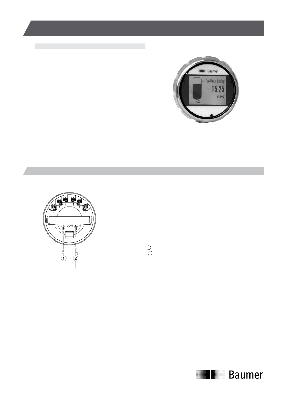
Electrical connection
Terminal 1 - 4-20 mA loop powered (Supply)
Terminal 2 - 4-20 mA loop powered (Supply)
Terminal 3 - Relay 1 - NO
Terminal 4 - Relay 1 - NO
Terminal 5 - Relay 2 - NO
Terminal 6 - Relay 2 - NO
Programming connect the FlexProgrammer to the FlexView, DFO.
Com. 1-Red clip it is not necessary to disconnect
Com. 2-Black clip the 4-20 mA loop to the FlexView, DFO display
The electrical installation must always be according to national standards and regulations.
Installation must be performed by trained staff only and always according to the wiring diagram.
Shielded twisted pair cable is recommended. Correct and safe installation and operation of the FlexView, DFO is dependent on proper transport,
storage, installation and operation.
Before switching on or off the power, it must be ensured that no other equipment is affected and that the correct voltage is used.
If in hazardous area (EX-area) installation must be according to the ATEX specifications and local standards and regulations – see separate
instructions in “Operation Instructions FlexView, DFO”.
Different ways of mounting are available.
Mounted in the housing of an instrument as a pre-mounted display, the FlexView, DFO is selected without or with relay output. When new
instruments PFMx, LFPx, AFKx etc. are delivered with FlexView, DFO, terminal 1 and 2 are not connected. In this case the FlexView, DFO will
have power and data through a special digital communication cable. The instrument can then also be programmed directly through the FlexView,
DFO display, by selecting its DTM-file.
Alternatively the FlexView, DFO is delivered in a Ø80 mm housing for separate wall mounting.
1
2
(When new instruments PFMx, LFPx,
AFKx etc. are delivered with FlexView,
DFO terminal 1 and 2 are not connected.
Then FlexView, DFO will have power and
data through a special flat cable.
The connected instrument can also be
programmed through the FlexView, DFO
display, by selecting its DTM-file)
Installation Manualwww.baumer.com
Page 1 Design and specifications subject to change without notice
Page 2
Page 2
Design and specifications subject to change without notice
Installation Manual
www.baumer.com
Selectable views
Value Analog Bar graph Tank illustration
Small / Large w. Bar graph / Value Vertical / horizontal Tank / Bottle
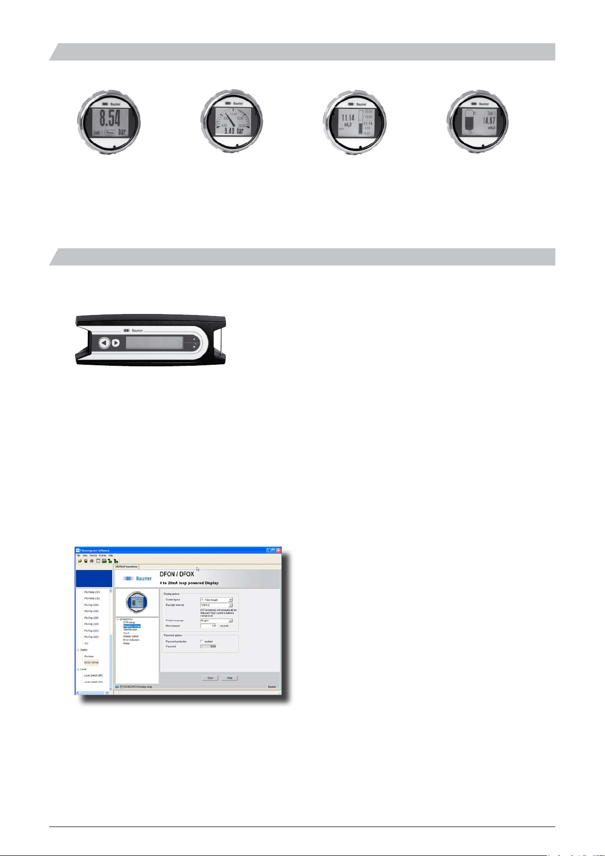
Programming by FlexProgrammer and/or touch screen
The FlexProgrammer 9701 is a dedicated tool to configure all Baumer configurable products.
FlexProgrammer, No. : 9701.0001
The FlexProgrammer interface unit will be delivered complete including
- CD with FlexProgram software
- Product drivers (DTM-files)
- USB cable
- Cable with 2 alligator clips
- Cable with M12 connector
For programming by the FlexProgrammer 9701 you will need to download tthe software from the Baumer homepage.
Instructions for use can be found under « Help »
If relays is to be activated in an instrument delivered with relays ”not activated”, please order an activation code from Baumer by
informing of the serial number of the instrument (the code is unique for each instrument). The activation code must be entered
under ”Identification” in the Flexprogramme (it cannot be entered using the touch screen).
Order option: DFO-SW.
Page 3

Configuration
see page 4
Screen layout
Colour
Normal backlight colour
(White/Red/Green)
Backlight
Intensity
Backlight intensity
(10 .. 140%)
Password enable Enable / Disable
MENU
Display setup
Password
New password Input new password
Attached instrument
Display name of
attached instrument
Attached instrument
Attached instr. menu
Access instrument
specific menu
Menu timeout
Statistics
Diagnostics
Demo setup Select demo mode Disabled/Static/Cyclic
Static display value
Input value used
in static demo mode
Factory settings Load Factory settings
Service menu For service personnel
Select between several display designs
Select idle time before menu reset
Min./max. value
High/low errors
Uptime since power-on/restart
Page 3 Design and specifications subject to change without notice
Installation Manualwww.baumer.com
Programming
Page 4

Identification
Input 100%
Loop current at 100%
(e.g. 20 mA)
Input 0%
Loop current at 0%
(e.g. 4 mA)
Input
Damping 0 = off / 1…30 sec.
Liniarization
correction
Enable / Disable
Display 100%
Displayed value
at 100% input
Display 0%
Displayed value
at 0% input
Decimals Digits after point
Display output Units Pressure units
Temperature units
Electric units
Configuration
Other units
Abs./Rel.
Select Absolute/Relative
or none
High error High error limit
MENU
High error indication
High error backlight
Error/warning setup
High warning Same as for high error
Display setup
Low warning Same as for high error
(see page 3)
Low error Same as for high error
Diagnostics
Relay 1 mode AO / AC / NO / NC
Relay 1 set point Point at which relay sets
Relay 1 reset point Point at which relay resets
Relay setup
Relay 2 mode
AO / AC / NO / NC
Relay 2 set point Point at which relay sets
Relay 2 reset point Point at which relay resets
This menu section is only accessible when the relays are activated
TAG No. / Serial No. / Date / Prod.date
Programming
www.baumer.com
Design and specifications subject to change without notice
5850-036_EN/2012-04-02 This data sheet may only be reproduced in full.
Installation Manual
Page 4
 Loading...