

Page 1
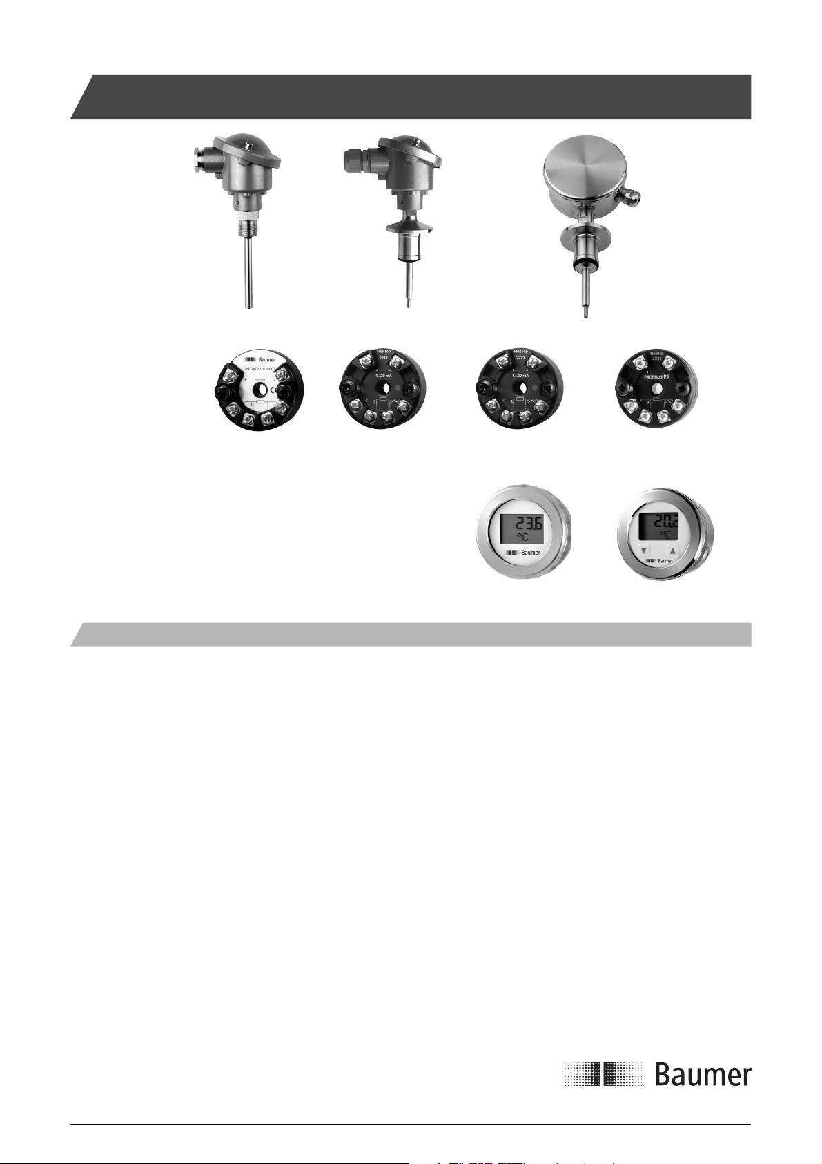
CombiTemp Temperature Measuring System
Housing
DIN-B
Standard or
Ex ia safety
Transmitters
FlexTop 2201 FlexTop 2211 FlexTop 2221 FlexTop 2231
Displays
The process connections shown
are examples.
Description
DIN-B
Ex n safety
Ø80 mm
stainless steel
FlexView BattTemp
CombiTemp comprises a series of basic elements which can be
combined to various temperature sensors and transmitters. Being a
building block system CombiTemp offers a great fl exibility in respect to
modifi cation, service and maintenance.
The basic components in the system are:
Housing: DIN-formB or Ø80mm stainless steel
Process connection: Refer to the data sheet
FlexTop transmitters: 2201, 2211, 2221, 2231
FlexView 4...20 mA LC-display
BattTemp, Battery operated Pt100 LC-display
The parts can be assembled by the user or delivered assembled and
calibrated, if relevant. However, an Ex ia or Ex n approved product will
always be assembled at the factory.
All documentation can be found at www.baumerprocess.com
This Ex-approved product is manufactured by:
Baumer A/S
Jacob Knudsens Vej 14
DK-8230 Aabyhoej
Denmark
Please refer to the relevant data sheets and installation manuals for
each product:
Product Data Sheet Manual
CombiTemp 2000-1 This manual
FlexTop2201 2201-1 2201-8906
FlexTop2211 2211-1 2211-8900
FlexTop2221 2221-1 2221-8900
FlexTop2231 2231-1 2231-8900
FlexView 9401-1 9401-8904
BattTemp 2400-1 2400-8900
Installation Manual 5850-008www.baumerprocess.com
Page 1 Design and specifi cations subject to change without notice
Page 2

Technical Data, General
Environmental conditions
Media temperature, std. -50...400°C
Surface sensor -40...150°C
Ambient temperature -40...160°C
(or max. temperature range for display/transmitter)
Humidity < 100% RH, condensing
(or max. humidity for display/transmitter)
Protection class DIN housing IP 65
ø80 mm housing IP 65 + IP 66
Vibrations GL, test 2
(sensor tubes < 200 mm only)
Disposal of product and packing
According to national laws or by returning to Baumer
Sensor tube and connection
Material Acid-proof, stainless steel
(AISI 316L/W.1.4404)
Media pressure Max. 16 bar
Time constant t
Mechanical tolerances ISO 2768-m
See table below
0.5
Sensor element
Sensor type Pt100, Class A or B
Pt1000, Class B
Accuracy DIN/EN/IEC 60751
1/1 DIN B: ±(0.3 + 0.005 x t) °C
1/3 DIN B: +1/3 x (0.3 + 0.005 x t) °C
1/6 DIN B: +1/6 x (0.3 + 0.005 x t) °C
1/1 DIN A: +(0.15 + 0.002 x t) °C
Safety Instructions Ex-Application - Confi guration
This instrument is built and tested ac cord ing to the current EU-directives and packed in technically safe con di tion. In order to main tain this
condition and to ensure safe op er a tion, the user must follow the hints
and warnings given in this instruction.
During the installation the valid national rules have to be observed.
Ignoring the warnings may lead to severe per son al injury or substantial
damage to property.
The product must be op er at ed by trained staff. Correct and safe
operation of this equipment is de pend ent on proper transport, storage,
installation and op er a tion.
All electrical wiring must conform to local stand ards. In order to prevent
stray elec tri cal radiation, we rec om mend twisted and shielded input
cables, as also to keep power sup ply cables separated from the input
cables. The con nec tion must be made ac cord ing to the connecting
di a grams.
Before switching on the power supply take care that other equip ment
is not af fect ed. Ensure that the supply voltage and the conditions in the
environment comply with the spec i fi ca tion of the de vice.
Before switching off the supply voltage check the possible effects on
other equipment and the processing system.
WARNING
For electrical installation and com mis sion ing of explosion protected
devices, the data given in the con form i ty cer tifi cate as also the local
reg u la tions for installation of elec tri cal apparatus within explosion pro tect ed areas must be considered. The intrinsically safe versions can be
mounted in the explosion hazarded area according to its spec i fi ca tion
only con nect ed to a certifi ed intrinsically safe supply loop with the cor re spond ing electrical values.
Valid for FlexTop 2201 / 2211 / 2221 and FlexView:
None of the two types of FlexProgrammer confi guring unit must be
connected to the FlexView within the hazardous area.
Confi guring procedure:
a) Disconnect mains from the 4...20 mA loop circuit.
b) Disconnect the product from the circuitry within
the hazardous area.
c) Bring the product to the safe area.
d) Connect the FlexProgrammer and perform the
confi guring session.
e) Re-install the product in the hazardous area.
f) Connect the power supply to the circuit.
Valid for FlexTop 2221 only:
Confi guration of the FlexTop2221 can be made within the hazardous
area by means of a handheld HART confi gurator, providing the
precautions and guidelines described in the product´s manual are
observed.
Valid for FlexTop 2231 only:
Confi guration of the FlexTop2231 can be made within the hazardous
area by means of a Profi bus PA confi gurator, providing the precautions
and guidelines described in the product´s manual are observed.
WARNING
This product contains no replaceable parts.
In case of malfunction the product must be shipped to Baumer for
repair.
WARNING
Products with painted and/or plastic surfaces (e.g. display) imply a risk
of electrostatic charging.
To prevent electrostatic hazard - do only clean with a moist cloth.
After mounting the device - do check that the housing has a ground
potential.
Installation Manual 5850-008www.baumerprocess.com
Page 2 Design and specifi cations subject to change without notice
Page 3
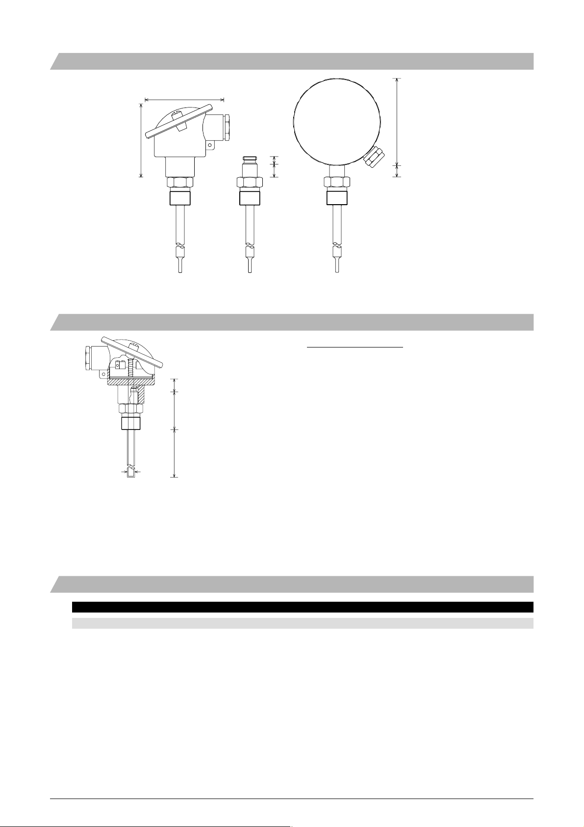
Dimensional Drawings - Mounting Details
[mm]
76
71
7.5
12.5
Male Nipple G1/2A Male Nipple G1/2A Male Nipple G1/2A
mounted on DIN B housing mounted on ø80 mm housing
Sensor inserts
Calculation of insert length:
When ordering an insert the length must be calculated from the
formula:
85
11
Housing shaft {8}
Total body length
Sensor length (L)
DIN housing with G1/2A male nipple connection
and sensor insert
Note {8}
Housing shaft DIN housing: 11.5 mm
ø80 housing: 6.5 mm
Time Constant τ
0.5
Insert length = Sensor length + total body length + housing shaft
(Total body length can be calculated from the dimensional drawings on
pages 6 and 7)
Example.
Insert for a G1/2A male nipple sensor in a DIN housing, 100 mm
sensor tube, normal response sensor tip:
Housing shaft = 11.5 mm
Total body length = 27.5 + 12.5 = 40 mm (see page 6)
Sensor length = 100 mm
This insert must be ordered with a 151.5 mm sensor tube.
Sensor type Liquids Air
Dimension Response Insert 0.4 m/sec. 3 m/sec. 0 m/sec.
ø6 mm tube fast < 1.5 sec. < 21.4 sec. < 135.6 sec.
ø8 mm tube fast < 1.5 sec. < 33.6 sec. < 181.0 sec.
ø10 mm tube fast < 1.5 sec. < 46.8 sec. < 238.9 sec.
ø12 mm tube fast < 1.5 sec. < 59.9 sec. < 311.4 sec.
ø6 mm tube normal < 6.1 sec. < 27.2 sec. < 137.8 sec.
ø8 mm tube normal < 7.6 sec. < 47.7 sec. < 200.9 sec.
ø10 mm tube normal < 11.1 sec. < 57.8 sec. < 270.6 sec.
ø12 mm tube normal < 16.2 sec. < 70.8 sec. < 319.8 sec.
ø8 mm tube normal 5.6 mm < 13.6 sec. < 51.1 sec. < 253.1 sec.
ø10 mm tube normal 5.6 mm < 28.1 sec. < 67.0 sec. < 271.1 sec.
ø12 mm tube normal 5.6 mm < 31.3 sec. < 82.3 sec. < 289.3 sec.
Surface sensor, fl ush mounted < 1.0 sec.
Installation Manual 5850-008www.baumerprocess.com
Page 3 Design and specifi cations subject to change without notice
Page 4

Technical Data, Ex ia IIC T4/T5, ATEX II 1G Approval
Product Identifi cation
The label at the product will show the type no. like this:
814x xxxx xxxx xx4 xxxx + xxxx xxxx + xx xx-xxx
CombiTemp no. + FlexTop no. + FlexView/BattTemp no.
The complete confi guration will be referred to as CombiTemp.
A CombiTemp with a type no. with the upmentioned structure is
Ex ia IIC T4/T5, ATEX II 1G approved in accordance with the current
EU-directives.
Ex- data for the below listed confi gurations
Ø80 housing: FlexTop 2201 / 2211 / 2221 / FlexView
DIN-B housing: FlexTop 2201 / 2211 / 2221
Internal inductivity L
Internal capacity C
Barrier data U < 28 Vdc ; I < 0.1 A ; P
Temperature class T4: -20 < T
T5: -20 < T
< 11 µH
i
< 36 nF
i
< 70°C
amb
< 60°C
amb
< 0.7 W
The CombiTemp must be installed in accordance with prevailing
guidelines for zone 0 or 1, and a certifi ed, intrinsically safe zener
barrier or isolation barrier with the listed maximum values must be
used.
Ex- data for the below listed confi gurations
Ø80 housing: FlexTop 2231
DIN-B housing: FlexTop 2231
Internal inductivity L
Internal capacity C
Coupler/link FISCO standard;
Zener barrier U < 20 Vdc ; I < 0.1 A ; P
Temperature class T4: -30 < T
T5: -30 < T
The CombiTemp must be installed in accordance with prevailing
guidelines for zone 0 or 1, and a certifi ed, intrinsically safe zener
barrier or isolation barrier with the listed maximum values must be
used.
< 10 µH
i
< 2 nF
i
U < 17.5 Vdc ; I < 215 mA ; P
< 0.75 W
< 85°C
amb
< 60°C
amb
< 2 W
Ex- data for the below listed confi guration
Ø80 housing: BattTemp
Temperature class
Battery: Energizer Lithium FR6 L91 AA
T4: -10 < T
T5: -10 < T
< 70 °C
amb
< 50 °C
amb
Battery: Duracell Alkaline MN1500 LR6 AA
T3: -10 < T
T4: -10 < T
< 70 °C
amb
< 60 °C
amb
The CombiTemp must be installed in accordance with prevailing
guidelines for zone 0 or 1. However, being a battery operated
instrument the installation does not involve a barrier.
CAUTION: Replacement of the battery must be done
outside hazardous areas.
The BattTemp is battery supplied and must not be connected to any
external power supply, nor to a 4...20 mA loop circuit.
When the BattTemp is installed in a hazardous area the battery clip
must be mounted. Observe the polarity of the battery.
BattTemp contains no repairable parts and must be replaced as a unit
in case of malfunction. It has no need for preventive maintenance,
except replacement of the battery.
Confi guring by the push buttons is allowed within the hazardous area.
Battery
Battery clip
+
Terminals
for Pt100 sensor
Ex-Application Example
230 Vac
RTD
Zone 0/1 Safe area
- +
2 - + 1
FlexTop 2211 FlexView Isolation Barrier Power Supply
CombiTemp
3 4
1 2
+ -
24 VDC 4...20 mA
Installation Manual 5850-008www.baumerprocess.com
Page 4 Design and specifi cations subject to change without notice
Page 5

Technical Data, Ex nA II T4/T5, ATEX II 3G Approval
Product Identifi cation
The label at the product will show the type no. like this:
814x xxxx xxxx xx5 xxxx + xxxx xxxx + xx xx-xxx
CombiTemp no. + FlexTop no. + FlexView/BattTemp no.
The complete confi guration will be referred to as CombiTemp.
A CombiTemp with a type no. with the upmentioned structure is
Ex nA II T4/T5, ATEX II 3G approved in accordance with the current
EU-directives.
Ex- data for the below listed confi gurations
Ø80 housing: FlexTop 2201 / 2211 / 2221 / 2231/FlexView
DIN-B housing: FlexTop 2201 / 2211 / 2221 / 2231
Temperature class T4: -20 < T
T5: -20 < T
The CombiTemp must be installed in accordance with prevailing
guidelines for zone 2 without a barrier.
WARNING: Do not open when energised.
< 70°C
amb
< 60°C
amb
Ex- data for the below listed confi gurations
Ø80 housing: BattTemp
Temperature class
Battery: Energizer Lithium FR6 L91 AA
T4: -10 < T
T5: -10 < T
< 70 °C
amb
< 50 °C
amb
Battery: Duracell Alkaline MN1500 LR6 AA
T3: -10 < T
T4: -10 < T
< 70 °C
amb
< 60 °C
amb
Warning: Observe battery ambient temperature !!!
The CombiTemp must be installed in accordance with prevailing
guidelines for zone 2.
CAUTION: Replacement of the battery must be done
outside hazardous areas.
The BattTemp is battery supplied and must not be connected to any
external power supply, nor to a 4...20 mA loop circuit.
When the BattTemp is installed in a hazardous area the battery clip
must be mounted. Observe the polarity of the battery.
BattTemp contains no repairable parts and must be replaced as a unit
in case of malfunction. It has no need for preventive maintenance,
except replacement of the battery.
Confi guring by the push buttons is allowed within the hazardous area.
Battery
Battery clip
Terminals
for Pt100 sensor
Electrical Connection Application
CombiTemp Gland Cable diameter Gland torque
mm Nm
Ø80 mm housing M16 3...9 8
DIN-B housing M20 8...13 6
Warning: If the CombiTemp is to be installed in ambient
temperature exceeding 70°C a proper cable should be installed.
CombiTemp
- +
4...20 mA
we
6
2 1
Zone 2 Safe area
RTD
5
4
3
- +
24 VDC
230 Vac
3 4
1 2
+ -
FlexView FlexTop 2211 Power supply
Installation Manual 5850-008www.baumerprocess.com
Page 5 Design and specifi cations subject to change without notice
Page 6

Mounting the ø80 mm Housing
35 Nm
2 Nm
Installation Manual 5850-008www.baumerprocess.com
Page 6 Design and specifi cations subject to change without notice
Page 7

Mounting the DIN-B Housing
2mm 2 Nm
35 Nm
Installation Manual 5850-008www.baumerprocess.com
Page 7 Design and specifi cations subject to change without notice
Page 8

4-wire Sensors Double Elements
White White Red Red White White Red Red
Warning:
One of the wires may not be
connected in case of a 3-wire
connection to the temperature
transmitter
Application Photos
ø80 mm housing with FlexView Cut through DIN - B housing ø80 mm housing with 2 glands
Gland (blind plug at the rear) FlexTop 2201 temperature transmitter Cover not mounted
Clamp connection G1/2A male nipple connection 3A connection at the rear
Fast response sensor Normal response sensor Fast response sensor
5850-008-UK/2008-04-25/Rev. A1 This data sheet may only be reproduced in full.
Installation Manual 5850-008www.baumerprocess.com
Page 8 Design and specifi cations subject to change without notice
 Loading...