

Baumer CleverLevel LFFS-1, CleverLevel LFFS-4, CleverLevel LFFS-3, CleverLevel LFFS-2 Operating Instructions Manual
Page 1

www.baumer.com Operating instructions: 11109132 09 EN Page 1 / 20
Safety instructions
2019-03-20 Design and specifications subject to change without notice
This instrument is constructed and tested according to the current EUdirectives and packed in technically safe condition. In order to maintain
this condition and to ensure safe operation, the user must follow the
instructions and warnings given in this instruction.
During the installation local standards have to be observed. Ignoring the
warnings may lead to severe personal injury or substantial damage to
property.
The product must be operated by trained staff. Correct and safe operation of this equipment is dependent on proper transport, storage, installation and operation.
All electrical wiring must conform to local standards and the connection
must be made according to the connecting diagrams.
Before switching on the power supply take care that other equipment is
not affected. Ensure that the supply voltage and the conditions in the
environment comply with the specification of the device.
Before switching off the supply voltage check the possible effects on
other equipment and the processing system.
To obtain the specified protection degree, the LFFS must be mounted
with a compliant cable.
Description
The Level Switch LFFS designed to detect levels in tanks, media separation and provide empty-pipe detection or dry-run protection
for pumps.
By means of the FlexProgrammer 9701 the output can be configured to either NPN, PNP or digital output signal. A damping of the
output signal can be activated in case of a fluctuating media level, e.g. during tank filling.
The measurement is precise and unaffected by the mounting position in the tank. In the Flex-software a compensation for foam,
bubbles and condensate as well as viscous media can be set.
The Flex-software also features an adjustment facility making the user able to adjust the sensor to a specific media.
The Level Switch LFFS measures liquids such as water and beer as well as viscous, sticky fluids, such as honey, yoghurt, toothpaste and ketchup. Even dry medias can be measured, e.g. sugar or flour.
The Level Switch LFFS is resistant against CIP and SIP agents.
Hygienic installation is also possible with the comprehensive range of accessories, see the overview at page 6.
WARNING
When the top cover is removed, do not look directly at the blue LED with unshielded eyes or damage to retina may occur!
This product contains no replaceable parts. In case of malfunction the product must be shipped to Baumer for repair.
Operating instructions
CleverLevel switch, LFFS
CleverLevel switch, type LFFS is an universal level switch, which
can be used for all applications in liquids and solids with a DCvalue above 1.5
Page 2

www.baumer.com Operating instructions: 11109132 09 EN Page 2 / 20
Mounting
Operating instructions
CleverLevel switch, LFFS
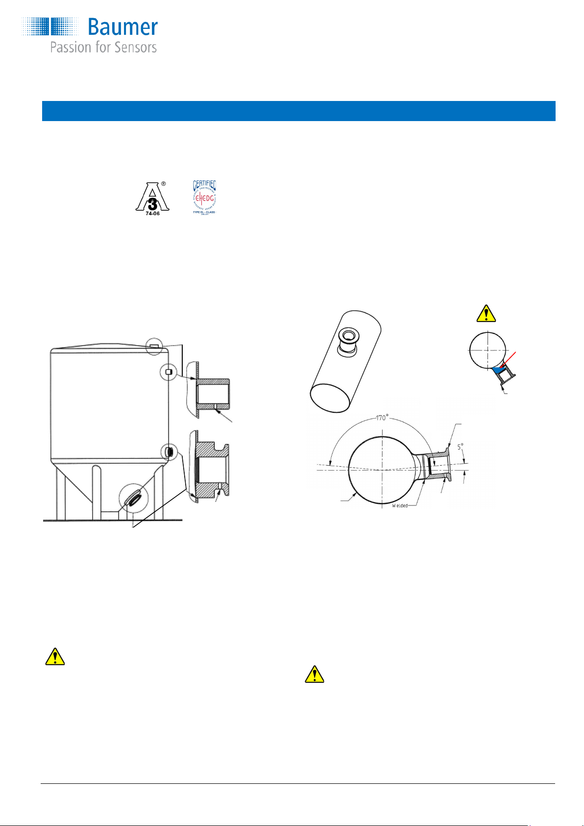
Please refer to “Accessories” data sheet. The welding part has
an engraved mark or a leak hole. When the product has been
mounted and correctly tightened the gland or M12 plug will
align with this mark.
Make sure that the gland/plug is pointing downwards to prevent fluids from penetrating into the instrument.
Use only the authorised special designed accessories. The
product warranty is void when installed with other adapters.
Do not use PTFE, fibre or other gaskets. The PEEK tip against
the stainless steel welding part will perform a hygienic tightening provided that the guidelines have been followed.
Due to the measuring principle it is essential that the sensor tip
can “see” an ample amount of the metal shaft or welding part.
Dimensions
Mounting instructions for sliding connection:
1) Clean the sliding shaft.
2) Mount the smallest ring against the media as indicated.
3) Tighten the G1/2 Hygienic sliding nipple at 25...30 Nm.
4) Replace the Washer ring kit when one or both parts are
permanently deformed or stick to the shaft of the sliding
connection.
The Level Switch LFFS with sliding connection can be mounted
in installations with a static pressure up to 16 bar.
To prevent personal injuries or property damage it is essential
that the safety wire is mounted correctly and is undamaged.
WARNING
Compression ring kit
ZPX1-006 for sliding
version
G 1/2 A hygienic sliding connection BHC 3A DN38 hygienic G 1/2 A hygienic
Measuring principle
An electrode inside the sensor tip builds a capacitor together with the surroundings. The medium with its dielectric constant (DC value) is defining
the capacitance value. A resonance circuit is created in combination with a
coil in the sensor head. Switching signal tripping is according to the measured resonance frequency and the programmed trigger thresholds.
Page 3

Operating instructions
CleverLevel switch, LFFS
Mounting
www.baumer.com Operating instructions: 11109132 09 EN Page 3 / 20
NOTE
The M12 cable rotating nut must be tightened by hand force only.
Max. torque is 0.6 Nm. Do not use any tool.
Refer to www.baumer.com for O-rings, gaskets and other accessories.
If the PEEK sealing rings for sliding connection is damaged or seriously scratched, the instrument or sealing rings should be replaced
(type ZPX1-006).
1) Use only a 3-A approved counterpart.
2) The leak detection port should be visible and drained.
3) Mount the adapter in a self-draining position/angle.
4) Level the inner surface of the pipe with the counterpart.
After installation:
Check the leak tightness of the sleeve.
Check the tightness of cable glands or M12 plug.
Example
with ZPW2-626
Example with
ZPW3-321
Example with
ZPW2-621
Leak detection port
must be placed at the
lowest possible position.
Fitted
incorrectly
Cannot be
drained
WARNING
5) The 3-A mark or the arrow shall be placed upwards.
6) Welding should be grinded to Ra ≤ 0.8.
7) Tighten the instrument in the adapter with a torque of 15...20 Nm.
If the seal is leaking and the media appears in the leak detection
port, the seal is to be changed immediately.
Before reassembly, clean the hole and inside of the connection with
detergent and sanitising liquid. Use a small brush. Verify that all of
the inside area is completely clean.
Reassemble and verify that the connection is tight.
Do not use Teflon, elastomer or other types of gaskets for the hygienic process connection featuring a conical seal.
The industrial versions with thread must be sealed e. g. by gasket or
Teflon® tape and tightened into the counterpart.
Installation of hygienic 3-A approved and EHEDG certified products,
please refer to below:
The switch provides IP67 protection in cable version or if installed
with IP67-compliant M12 cable. Switch installation using an IP69K
cable ensures IP69K conformity.
Stainless
steel tube
NOTE
The CleverLevel switch is to be mounted in a closed metal pipe, tank
or container.
Page 4

Refer to adaptor instruction manual for further information
NOTE:
The LFFS must be mounted in a Baumer mounting
connection.
If not, Baumer do not guarantee correct function or
tightness.
Operating instructions
CleverLevel switch, LFFS
Mounting connections
ISO2852 SMS 1145 Welding
DN38: ZPH3-3213 DN51: ZPH1-3236 for tank
DN51: ZPH3-3216 ZPW3-321
Varivent®, type N DIN 11851 Welding
ZPH3-324E DN25: ZPH3-3221 for tank
Varivent®, type F DN40: ZPH3-3224 ZPW3-322
ZPH3-344F DN50: ZPH3-3225
DIN 11864-1-A Welding Ø35
DN 40: ZPH3-3254 for tank/tube
DN 50: ZPH3-3255 ZPW2-324
Adapter Welding
EH FTL to pipe extrusion
G¾A: ZPH1-32BA DN 25...DN50: ZPW2-326
G1A: ZPH1-32CB DN 65...DN150: ZPW2-327
VS
G¾A: ZPH1-32BC
G1A: ZPH1-32CD
Adapter Adapter, industrial Adapter, industrial
G½ → G1 G½ → G1: ZPI1-32B Sliding connection
ZPH1-32C0 G½ → G1½: ZPI1-32D G½ → G½ DIN 3852-E
G½ → G2: ZPI1-32E ZPI1-32A
Welding
for tank
ZPW2-621
Welding
for pipe end
ZPW2-626
www.baumer.com Operating instructions: 11109132 09 EN Page 4 / 20
On a welding adapter there is an
arrow or a 3A logo.
This must be placed upwards when
welding the adapter into a tank
(horizontal position).
This assures that the electrical connection will be pointing downwards
(opposite of the arrow; 3A logo)
Page 5

Media temperature and external length for sliding connection
Operating instructions
CleverLevel switch, LFFS
Media temperature °C
120
115
110
105
100
95
90
85
80
75
50 55 60 65 70 75 80 85 90
Ambient temperature °C
LFFS-xx1.x / LFFS-xx2.x LFFS-xx3.x and LFFS-xx4.x
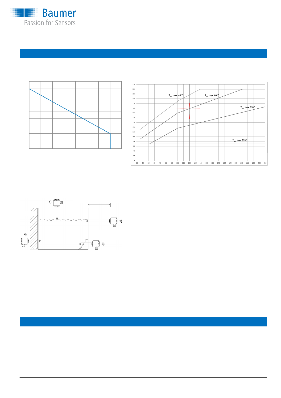
External length of sliding connection
Media temperature °C
External length
See example
The drawing shows how the sliding connection can be
used for at least 4 applications:
1) Mounted at the top of a tank to adjust to a
maximum level.
2) Serving as a cooling neck in high media
temperature applications.
3) Adjusted to place the sensor tip deeper
inside the tank.
4) To reach in through insulation material.
It is essential that the max. ambient temperature for the electronics is
never exceeded (85°C). For ATEX approved products please refer
ATEX data.
Example, how to read External length curve:
Example: Media temperature / Ambient temperature / External length
160°C 60°C 120 mm
A 250 mm sliding connection is mounted in a tank with a total in-
sertion length of 130 mm. Hence the external length of the sliding
connection will be 250 – 130 = 120 mm.
The media temperature will be max. 160 °C.
Read the x-axis at 120 mm and the y-axis at 160°C and find that
the ambient temperature must be kept below 60°C.
In case the radiated heat from the tank will cause a higher ambient
temperature at the housing efficient insulation of the tank must be
established.
www.baumer.com Operating instructions: 11109132 09 EN Page 5 / 20
For CIP/SIP Media temperature, max. 140°C
Ambient temperature, max. 60°C
Duration, max. 1 hour
When re-ordering a CleverLevel switch
If a new CleverLevel switch is installed in an existing application, it is normally a “plug-n’-play” operation.
If the settings of the level switch was changed from standard factory settings, it is necessary to re-adjust the new switch to same
as the “old” switch. It is possible to save the settings of the “old” switch on the PC and download those again to the new level
switch.
The factory setting of the sensitivity of the media may vary up to ±5%. This means that if an very exact set point is required, a new
teach-in or adjustment by the FlexProgram must be performed.
Page 6

Operating instructions
CleverLevel switch, LFFS
Teach-In using the FlexProgram and FlexProgrammer 9701
Sophisticated settings for Teach-In as well as output type, diagnostics, data logging, tag no. and damping can be configured using
the FlexProgrammer 9701. Integrated HELP-menus will give full instruction.
Press or to browse the menus
to access current menu point
to return to previous menu
and simultaneously to reset FlexProgrammer
and go in sleep mode
Teach-In
Press
and simultaneously
Select Menu “Teach-In”
Search for product
= Product LFFS/LBFS
At empty tank setting 0%
At full tank setting 100%
Manually Teach-In
Make sure that power is on before Teach-In.
For best Teach-In it is important the product is fixed in the final application.
During Teach-In mode the light intensity of the LED will decrease, please protect your eyes.
Step To do LED Result
1
Connect terminal ”Teach-In” to
- VDC (T1 or T2) for 3,5 second
Flash 1 time per second
Ready for Teach-in
2
With no media present connect
”Teach-In” to - VDC shortly
Light on for 2 second and then flash
Register ”empty” state. Pls. See note
3
With media present connect
”Teach-In” to - VDC shortly
Light on for 2 seconds
Register ”full” state, stores the value and returns to
Normal operation with new setting
NOTE:
If the media is sticky, foamy, powdery or in other ways leaving parts of the media at the sensor tip this situation has to be established also during the Teach-In process. Otherwise a faulty calibration can be the result.
If Teach-In for some reason do not succeed, the CleverLevel Switch LFFS will enter “Error State” and automatically reload factory
settings . The factory settings can always be reloaded by connecting the terminal “Teach-In” to -VDC for more than 6.5 seconds.
A reloaded factory settings will be confirmed by pulsing light intensity 3 times.
Error state description LED Result
Error state Blinking, 3 × short and 1 × long Can normally be fixed by powering off and on and remake the Teach-In.
Alternatively remake the Teach-In configuration by use of the FlexProgram and the FlexProgrammer 9701
Using the FlexProgrammer 9701 alone and Teach-In
FlexProgrammer 9701 stand alone menu
Press
Turn on FlexProgrammer if in sleep mode
Empty configuration
Search for product
LFFS/LBFS configuration
Product LFFS / LBFS
TAG number xxxxxxxxxxxxxxx
Range min. x.x%
Range max. xx.x%
Damping x,x sec
Output config. Xxxxxxx
Trigger level xx,x%
Range hyst. x,xx%
Trigger hyst. x.xx%
www.baumer.com Operating instructions: 11109132 09 EN Page 6 / 20
Page 7

Electrical connection
Operating instructions
CleverLevel switch, LFFS
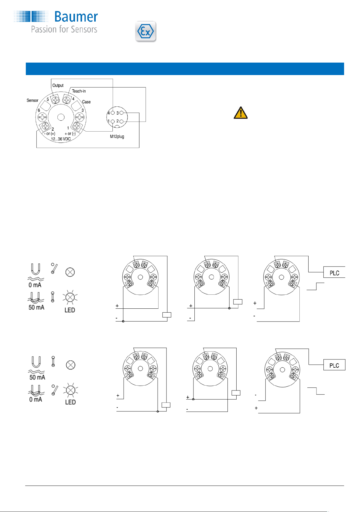
M12 plug: 1 Brown
2 White*
3 Blue
4 Black
WARNING
* To avoid unintended Teach-In, be aware
not to connect the Teach-In pin or expose it
to any electrical noise during normal operation.
Normally open - NO
Normally closed - NC
Electrical specifications:
Power supply 12,5...36 VDC, 35 mA max.
Output PNP, NPN or Digital
Max. 50 mA, short-circuit and high
temperature protected
1
2
5
1
2
5
1
2
5
1
2
5
1
2
5
1
2
5
www.baumer.com Operating instructions: 11109132 09 EN Page 7 / 20
Active “Low” NPN and Digital output
(-VDC +2,5V) ±0,5V, R
load
= 1 kΩ
Active “High” PNP and Digital output
(+VDC -2,5V) ±0,5V, R
load
= 1 kΩ
ATEX
Connection type Ambient temperature Media temperature
(max. allowed)
Note
G½ hygienic -40 … +85 °C +85 °C
3A DN38
-40 … +60 °C +95 °C 1)
-40 … +40 °C +115 °C 1)
100 mm -40 … +85 °C +85 °C
Sliding connection
-40 … +60 °C +155 °C 1)
-40 … +40 °C +175 °C 1)
250 mm -40 … +85 °C +85 °C
Sliding connection
-40 … +60 °C +195 °C 1)
-40 … +40 °C +200 °C 1)
Conditions for Ex certification
1) Provided that
the sensor tip
at the instru ment is the
only part in
contact with
the media
Page 8

Operating instructions
CleverLevel switch, LFFS
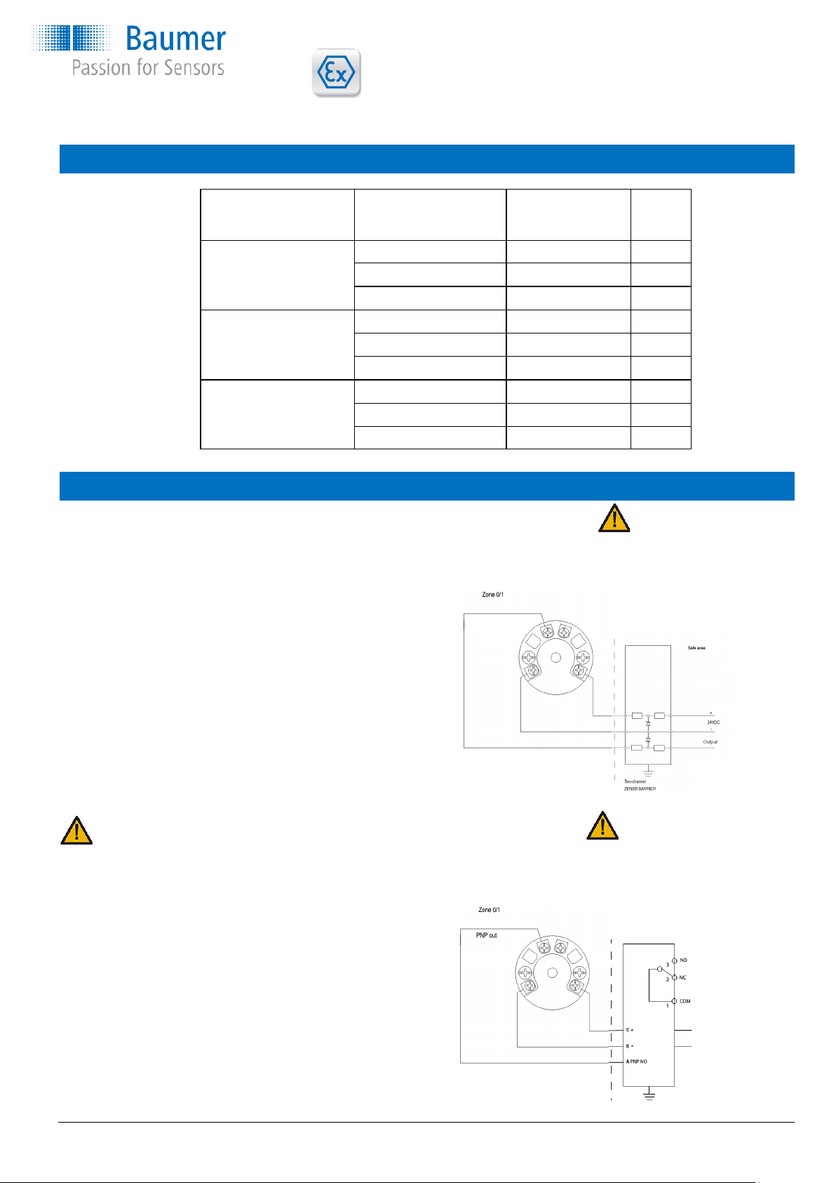
Ex ia IIC T5, ATEX II 1G - Installation
A Level Switch LFFS-1xx.x is Ex ia IIC T5, ATEX II 1G approved for application in hazardous areas in accordance with
the current EU directives. The product must be installed in
accordance with prevailing guidelines for zone 0 with a barrier
ATEX Gas ia
LFFS-1xx.x
with PNP output
Safe area
+ 22...120 VDC
or
- 90...253 VAC
Note:
For PNP output the barrier module
PFOFSI3-B25100-ALG-LS
is required for functional purposes.
PFOFSI3-B25100-ALG-LS
NPN out
LFFS-1xx.x
with NPN output
Note:
For NPN output only!
A standard barrier may be used
Standard barrier
Two-channel
ZENER barrier
www.baumer.com Operating instructions: 11109132 09 EN Page 8 / 20
Note:
There is an electrical connection between intrinsic safe
circuit and housing due to the measurement principle
ATEX Dust tD
A Level Switch LFFS-2xx.x is Ex tD A20 IP67 T100°C, ATEX II 1D
approved for application in hazardous areas in accordance with the
current EU-directives. The product must be installed in accordance
with prevailing guidelines for zone 20 without a barrier.
Ex-data
Supply range VDC 12,5...30
Load I <0.1 A
Temperature class T1...T5 Pls. see table top page 7
12,5...30
1
2
5
ATEX Gas nA
A Level Switch LFFS-3xx.x is Ex nA II T5, ATEX II 3G approved for
application in hazardous areas in accordance with the current EU
directives. The product must be installed in accordance with prevailing
guidelines for zone 2 without a barrier.
Ex-data
Supply range VDC 12,5...30
Load I <0.1 A
Temperature class T1...T5 Pls. see table top page 7
12,5...30
1
2
5
Ex-data
Supply range 24...30 VDC
Temperature class T1...T5 Pls. see above table
Internal inductivity Li <10 µH
Internal capacity Ci <3 nF
Barrier data U <30 VDC
I <0.1 A
P <0.75 W
Ex-Configuring
The FlexProgrammer 9701 configuring unit must not be connected to the CleverLevel Switch LFFS within the hazardous area.
Configuring procedure:
a) Disconnect mains from the 4...20 mA loop circuit.
b) Disconnect the Level Switch from the circuitry within the hazardous area.
c) Uninstall and bring the Level Switch to the safe area.
d) Connect the FlexProgrammer 9701 and perform the configuring session.
e) Re-install the Level Switch in the hazardous area.
Page 9

www.baumer.com Betriebsanleitung: 11109132 09 DE Page 9 / 20
Sicherheitshinweise
Dieses Gerät wurde gemäss den geltenden EU-Richtlinien gebaut und
geprüft und unter technisch sicheren Bedingungen verpackt. Um diesen
Zustand zu erhalten und einen sicheren Betrieb zu gewährleisten, muss
der Anwender die in dieser Anleitung gegebenen Anweisungen und
Warnhinweise befolgen.
Bei der Installation sind die vor Ort geltenden Vorschriften zu beachten.
Die Nichtbeachtung der Warnhinweise kann zu erheblichen Personenund Sachschäden führen.
Das Produkt darf nur von geschultem Personal bedient werden. Sachgemässer Transport sowie eine sachgemässe Lagerung, Installation
und Bedienung sind entscheidend für einen korrekten und sicheren
Betrieb dieses Gerätes.
Die gesamte elektrische Verkabelung muss den örtlichen Standards
entsprechen und die Anschlüsse müssen gemäss den Anschlussschemata ausgeführt werden.
Vor dem Einschalten der Spannungsversorgung ist darauf zu achten,
dass keine anderen Geräte beeinflusst werden. Es ist sicherzustellen,
dass die Versorgungsspannung und die Umgebungsbedingungen den
Spezifikationen für dieses Gerät entsprechen.
Vor dem Abschalten der Versorgungsspannung sind mögliche Auswirkungen auf andere Geräte und das gesamte System zu prüfen.
Um die spezifizierte Schutzklasse zu erreichen, müssen die entsprechenden Kabel verwendet werden.
Beschreibung
Der Füllstandsschalter LFFS eignet sich hervorragend für die Füllstandserkennung in Behältern, die Medientrennung sowie die
Erkennung leerer Rohre und den Trockenlaufschutz von Pumpen.
Mithilfe des FlexProgrammer 9701 kann der Ausgang als NPN-, PNP- oder ein digitales Ausgangssignal konfiguriert werden. Im
Falle eines veränderlichen Medienfüllstandes (z. B. während der Befüllung des Behälters) kann eine Dämpfung des Ausgangssignals aktiviert werden.
Die Messung erfolgt präzise und wird nicht von der Montageposition im Behälter beeinflusst. In der Flex-Software kann eine Kompensierung für Schaum, Blasen, Kondensat und viskose Medien eingestellt werden.
Die Flex-Software umfasst auch eine Einstellfunktion, die es dem Benutzer ermöglicht, den Sensor an ein bestimmtes Medium
anzupassen.
Der Füllstandsschalter LFFS misst Flüssigkeiten wie Wasser und Bier sowie viskose, klebrige Flüssigkeiten wie Honig, Joghurt,
Zahnpasta und Ketchup. Auch trockene Medien, wie z. B. Zucker oder Mehl, können gemessen werden.
Der Füllstandsschalter LFFS ist gegen CIP- und SIP-Mittel beständig.
Das umfangreiche Zubehörsortiment ermöglicht eine hygienegerechte Installation, siehe Übersicht auf Seite 6.
WARNUNG
Bei entferntem Deckel nicht mit ungeschützten Augen direkt in die blaue LED schauen, da die Netzhaut Schaden nehmen kann!
Dieses Produkt enthält keine austauschbaren Teile. Bei Fehlfunktion ist das Produkt zur Reparatur an Baumer einzusenden.
Betriebsanleitung
CleverLevel switch, LFFS
Der CleverLevel Switch LFFS ist ein vielseitiger Füllstandsschalter,
der für alle Anwendungen mit Flüssigkeiten und Feststoffen mit
einem DK-Wert über 1,5 eingesetzt werden kann.
Page 10

www.baumer.com Betriebsanleitung: 11109132 09 DE Page 10 / 20
Das Messprinzip
Montage
Betriebsanleitung
CleverLevel switch, LFFS
Eine Elektrode im Innern der Sensorspitze bildet zusammen mit der
Umgebung einen Kondensator. Das Medium mit der Dielektrizitätskonstante (DK-Wert) definiert den Kapazitätswert. In Kombination mit
einer Spule im Sensorkopf wird eine Resonanzschaltung gebildet.
Das Auslösen von Schaltsignalen erfolgt entsprechend der gemessenen Resonanzfrequenz und den programmierten Schwellenwerten für
die Auslösung.
Siehe Datenblatt „Zubehör”. Die Einschweissmuffe hat eine
eingravierte Markierung oder ein Bohrloch. Wenn das Produkt
montiert und richtig angezogen ist, stimmen Verschraubung
oder M12-Stecker mit dieser Markierung überein.
Bitte darauf achten, dass die Verschraubung bzw. der Stecker
nach unten zeigt, damit keine Flüssigkeit in das Gerät eindringen kann.
Ausschliesslich das zugelassene speziell angefertigte Zubehör
verwenden. Die Produktgarantie erlischt, wenn andere Adapter
installiert werden.
Bitte keine Dichtungen aus PTFE, Fasern oder sonstige Dichtungen verwenden. Wenn sich die aus PEEK bestehende Spitze gegen die Einschweissmuffe aus Edelstahl drückt, bildet
dies eine hygienegerechte Dichtung, vorausgesetzt die Richtlinien wurden befolgt.
Aufgrund des Messprinzips ist es wichtig, dass für die Sensorspitze ein ausreichend grosses Stück von Metallachse oder
Einschweissmuffe „sichtbar“ ist.
Dimensions
Montageanleitung für den verschiebbaren Anschluss:
1) Gleitachse reinigen.
2) Den kleinsten Ring in Richtung Medium anbringen.
3) Den hygienegerechten verschiebbaren Anschluss G1/2 mit
25...30 Nm festziehen.
4) Wenn eine oder beide Teile des Unterlegscheibensatzes
deformiert sind oder an der Achse des verschiebbar
Anschlusses anhaften, ist der Unterlegscheibensatz zu
ersetzen.
Der Füllstandsschalter LFFS mit verschiebbarem Anschluss eignet sich zum Einbau in Anlagen mit einem statischen Druck von
maximal 16 bar.
Um Personen- und Sachschäden zu vermeiden, ist es wichtig,
dass die Sicherheitskette richtig angebracht und unbeschädigt ist.
WARNUNG
Klemm-Ring-Kit
ZPX1-006 für verschiebbarem Anschluss
G 1/2 A hygienegerecht verschiebbarer Anschluss BHC 3A DN38 hygienegerecht G 1/2 A hygienegerecht
Page 11
Betriebsanleitung
CleverLevel switch, LFFS
Montage
www.baumer.com Betriebsanleitung: 11109132 09 DE Page 11 / 20
ANMERKUNG
Die M12-Kabel-Drehmutter darf nur von Hand angezogen werden.
Max. Drehmoment 0,6 Nm. Kein Werkzeug verwenden.
O-Ringe, Dichtungen und weiteres Zubehör sind im
www.baumer.com zu finden.
Falls die PEEK-Dichtringe des verschiebbaren Anschlusses beschädigt oder stark verkratzt sind, sollten das Gerät oder die Dichtringe
ausgetauscht werden (Typ ZPX1-006).
1) Nur Montageteile mit 3-A-Standard verwenden.
2) Die Kontrollbohrung muss sichtbar und selbstentleerend angeordnet sein.
3) Den Adapter so in einer Position bzw. einem Winkel montieren,
dass er von selbst abtropfen kann.
4) Die innere Oberfläche des Rohres mit dem Montageteil frontbündig abschliessen lassen.
Nach der Installation:
Dichtigkeit der Muffe überprüfen.
Dichtigkeit der Kabelverschraubungen oder M12-Stecker über-
prüfen
Beispiel mit
ZPW2-626
Beispiel mit
ZPW3-321
Beispiel mit
ZPW2-621
Die Kontrollbohrung
muss an der tiefstmöglichen
Position angeordnet werden
Nicht korrekt
eingesetzt
Kann nicht
abtropfen
WARNING
5) Die 3A-Markierung bzw. der Pfeil sollte nach oben zeigen.
6) Schweissnähte sollten so abgeschliffen werden, dass sie einen
Wert von Ra ≤ 0,8 aufweisen.
7) Gerät im Adapter mit einem Drehmoment von 15 ... 20 Nm festziehen.
Wenn die Dichtung undicht ist und die Medien in der Kontrollbohrung
sichtbar werden, muss die Dichtung sofort ausgetauscht werden.
Vor dem erneuten Zusammenbau die Bohrung und das Innere des
Anschlusses mit Reinigungsmittel und desinfizierender Flüssigkeit
reinigen. Eine kleine Bürste verwenden. Sicherstellen, dass die gesamte Innenfläche vollständig sauber ist.
Wieder zusammenbauen und überprüfen, ob der Anschluss dicht ist.
Keine Dichtungen aus Teflon, Elastomer oder andere Arten mit konischer Abdichtung für den hygienegerechten Prozessanschluss verwenden.
Die industriellen Versionen mit Gewinde müssen z. B. durch eine
Dichtung oder durch Teflon®-Band abgedichtet werden.
Für die Montage der hygienegerechten Produkte mit 3-A-Standard
und EHEDG-Zulassung siehe unten:
Der Schalter bietet IP67-Schutz in Kabelausführung oder bei Installation mit IP67-konformem M12-Kabel. Bei Installation des Schalters
mit einem IP69K-Kabel wird die IP69K-Konformität sichergestellt.
Edelstahlrohr
ANMERKUNG
Der CleverLevel Switch muss in einem geschlossenen Metallrohr,
Tank oder Behälter montiert werden.
Page 12

Weitere Informationen siehe Betriebsanleitung für
Anschlüsse
ANMERKUNG:
Der LFFS muss mit einem Montageanschluss von
Baumer montiert werden. Andernfalls übernimmt Baumer keine Garantie für korrekte Funktion oder Dichtigkeit.
Betriebsanleitung
CleverLevel switch, LFFS
Montageanschlüsse
ISO2852 SMS 1145 Einschweissmuffe
DN38: ZPH3-3213 DN51: ZPH1-3236 für Behälter
DN51: ZPH3-3216 ZPW3-321
Varivent®, Typ N DIN 11851 Einschweissmuffe
ZPH3-324E DN25: ZPH3-3221 für Behälter
Varivent®, Typ F DN40: ZPH3-3224 ZPW3-322
ZPH3-344F DN50: ZPH3-3225
DIN 11864-1-A Einschweissmuffe Ø35
DN 40: ZPH3-3254 für Behälter/Rohr
DN 50: ZPH3-3255 ZPW2-324
Adapter Einschweissmuffe
EH FTL für Rohr mit Auszug
G¾A: ZPH1-32BA DN 25...DN50: ZPW2-326
G1A: ZPH1-32CB DN 65...DN150: ZPW2-327
VS
G¾A: ZPH1-32BC
G1A: ZPH1-32CD
Adapter Adapter, Industriell Adapter, Industriell
G½ → G1 G½ → G1: ZPI1-32B verschiebbarer Anschl.
ZPH1-32C0 G½ → G1½: ZPI1-32D G½ → G½ DIN 3852-E
G½ → G2: ZPI1-32E ZPI1-32A
Einschweissmuffe für Behälter
ZPW2-621
Einschweissmuffe für Rohrende
ZPW2-626
www.baumer.com Betriebsanleitung: 11109132 09 DE Page 12 / 20
Auf dem Einschweissadapter befindet sich ein Pfeil oder ein 3A-Logo.
Diese müssen nach oben weisen,
wenn der Adapter in einen Behälter
eingeschweisst wird (horizontale
Position).
Dadurch ist gewährleistet, dass der
elektrische Anschluss nach unten
zeigt (dem Pfeil bzw. dem 3A-Logo
entgegengesetzt).
Page 13
Medientemperatur und externe Länge des verschiebbaren Anschlusses
Betriebsanleitung
CleverLevel switch, LFFS
Medientemperatur °C
120
115
110
105
100
95
90
85
80
75
50 55 60 65 70 75 80 85 90
Umgebungstemperatur °C
LFFS-xx1.x / LFFS-xx2.x LFFS-xx3.x und LFFS-xx4.x
Externe Länge des verschiebbaren Anschlusses
Medientemperatur °C
äußere Länge
siehe Beispiel
Die Skizze zeigt beispielhaft 4 verschiedene Anwendungsmöglichkeiten für den verschiebbaren Anschluss:
1) Von oben in den Behälter hineinragend zur
Einstellung des maximalen Füllstands
2) Als Kühlstrecke bei Anwendungen mit hoher
Medientemperatur
3) So eingestellt, dass die Sensorspitze tiefer in den
Behälter hineinragt
4) Durch Isoliermaterial hindurch in den Behälter
ragend
Es ist wichtig, dass die für die Elektronik gültige maximale Umgebungstemperatur (85 °C) nie überschritten wird. Bezüglich ATEXzugelassener Produkte siehe ATEX-Daten.
Beispiel: So ist die Kurve für die externe Länge abzulesen:
Beispiel: Medientemperatur / Umgebungstemperatur / Externe Länge
160°C 60°C 120 mm
Ein Schiebeanschluss von 250 mm Länge ist mit seiner gesamten
Einschublänge von 130 mm in einen Tank montiert. Seine externe
Länge beträgt daher 250 – 130 = 120 mm
Die Medientemperatur beträgt max. 160°C
Liest man den Schnittpunkt aus 120 mm auf der X-Achse und
160°C auf der Y-Achse ab, so ergibt sich, dass die Umgebungstemperatur unter 60°C gehalten werden muss.
Falls die Abstrahlwärme vom Behälter zu einer höheren Umgebungstemperatur am Gehäuse führt, muss für eine wirksame Isolierung des
Behälters gesorgt werden.
www.baumer.com Betriebsanleitung: 11109132 09 DE Page 13 / 20
Für CIP/SIP Medientemperatur max. 140 °C
Umgebungstemperatur max. 60 °C
Dauer max. 1 Stunde
Nachbestellung eines CleverLevel Switch
Wenn ein neuer CleverLevel Switch in einer bestehenden Anwendung installiert wird, geschieht dies in der Regel als „Plug-n'Play“.
Wurden die Standard-Werkseinstellungen des Füllstandsschalters verändert, muss der neue Schalter an die Einstellungen des
„alten“ Schalters angepasst werden. Die Einstellungen des „alten“ -Schalters lassen sich auf dem PC speichern und anschliessend in den neuen Füllstandsschalter herunterladen.
Die Werkseinstellungen der Sensitivität für die Medien können um bis zu ±5 % variieren. Wenn ein sehr genauer Sollwert erforderlich ist, muss daher ein neues Teach-in oder eine Anpassung durch FlexProgram durchgeführt werden.
Isolierung
Klumpige oder klebrige Medien
Page 14

Betriebsanleitung
CleverLevel switch, LFFS
Teach-In mithilfe von FlexProgram und FlexProgrammer 9701
Besondere Einstellungen für das Teach-In sowie Ausgangstyp, Diagnose, Datenerfassung, Messstellen-Nr. und Dämpfung können
mit dem FlexProgrammer 9701 konfiguriert werden. Eine vollständige Anleitung dazu ist im HILFE-Menü des Programms enthalten.
oder drücken, um durch das Menü zu navigieren
drücken, um den aktuellen Menüpunkt aufzurufen
drücken, um zum vorherigen Menü zurückzukehren
und gleichzeitig drücken, um FlexProgrammer
zurückzusetzen und in den Sleep-Modus zu schalten
Teach-In
Folgende Tasten drücken:
und gleichzeitig
Menü „Teach-In“ wählen
Produkt suchen
= Produkt LFFS/LBFS
Bei leerem Behälter Einstellung 0 %
Bei vollem Behälter Einstellung 100 %
Manuelles Teach-In
Vor Durchführung des Teach-In muss der Strom eingeschaltet werden.
Damit das Teach-In optimal durchgeführt wird, muss das Produkt in seiner endgültigen Anwendung montiert sein.
Während des Teach-In-Betriebs ist die Intensität der LED zum Schutz Ihrer Augen geschwächt.
Schritt Folgendes ausführen LED Ergebnis
1
Klemme „Teach-In“ für 3,5 Sek. an
-VDC (T1 oder T2) anschliessen
Blinkt 1-mal pro Sekunde
Bereit für Teach-In
2
Wenn noch keine Medien vorhanden sind,
„Teach-In“ kurz an -VDC anschliessen
Leuchtet 2 Sekunden
lang und blinkt danach
Registriert den Zustand „leer“. Bitte Anmerkung beachten
3
Wenn Medien vorhanden sind,„Teach-In“
kurz an -VDC anschliessen
Leuchtet 2 Sekunden
lang
Registriert den Zustand „gefüllt“, speichert den Wert und kehrt
mit den neuen Einstellungen zum Normalbetrieb zurück
ANMERKUNG:
Bei klebrigen, schäumenden, pulvrigen oder anderen Medien, von denen leicht Reste an der Sensorspitze haften bleiben, müssen
diese Bedingungen auch während des Teach-In-Verfahrens vorliegen. Andernfalls kann die Kalibrierung fehlerhaft werden.
Wenn das Teach-In nicht erfolgreich sein sollte, meldet der Füllstandsschalter LFFS einen „Fehlerstatus” und die Werkseinstellungen werden automatisch neu geladen. Die Werkseinstellungen können jederzeit neu geladen werden, indem die „Teach-In“-
Klemme länger als 6,5 Sekunden an -VDC angeschlossen wird. Neu geladene Werkseinstellungen werden durch dreimaliges Blinken bestätigt.
Beschreibung des
Fehlerstatus
LED Ergebnis
Fehlerstatus Blinkt 3-mal kurz und 1-mal
lang
Lässt sich in der Regel durch Aus- und Einschalten und erneutes TeachIn-Verfahren beheben.
Alternativ ist die Teach-In-Konfiguration mithilfe von FlexProgram und
dem FlexProgrammer 9701 erneut durchzuführen.
Verwendung des FlexProgrammer 9701 allein und zum Teach-In
FlexProgrammer 9701 - eigenständiges Gerät
Folgende Tasten drücken
Den FlexProgrammer einschalten, falls er sich im SleepModus befindet
Konfiguration löschen
Produkt suchen
LFFS/LBFS-Konfiguration
Produkt LFFS / LBFS
Messstellen-Nummer xxxxxxxxxxxxxxx
Messbereich min. xx.x%
Messbereich max. xx.x%
Dämpfung x,x sec
Ausgangskonfig. xxxxxxx
Trigger-Einstellung xx,x%
Messbereichs-Hyst. x,xx%
Trigger-Hyst. x.xx%
www.baumer.com Betriebsanleitung: 11109132 09 DE Page 14 / 20
Page 15
Elektrischer Anschluss
Betriebsanleitung
CleverLevel switch, LFFS
M12-Stecker: 1 Braun
2 Weiss*
3 Blau
4 Schwarz
WARNUNG
* Um ein unbeabsichtigtes Teach-In
zu vermeiden, ist darauf zu achten,
den Teach-In-Kontakt nicht anzuschliessen und im Normalbetrieb
keinem Elektrorauschen auszusetzen.
Schliesser – NO
Öffner – NC
Elektrische Daten:
Spannungsversorgung 12,5...36 VDC, 35 mA max.
Ausgang PNP, NPN oder Digital
Max. 50 mA, kurzschlussfest und
hochtemperaturfest
Low-aktiv NPN- und digitaler Ausgang
(-VDC +2,5V) ±0,5V, R
load
= 1 kΩ
High-aktiv PNP- und digitaler Ausgang
(+VDC -2,5V) ±0,5V, R
load
= 1 kΩ
1
2
5
1
2
5
1
2
5
1
2
5
1
2
5
1
2
5
www.baumer.com Betriebsanleitung: 11109132 09 DE Page 15 / 20
PNP Ausgang NPN Ausgang Digitaler Ausgang
Low-aktiv
High-aktiv
PNP Ausgang NPN Ausgang Digitaler Ausgang
Page 16
ATEX
Betriebsanleitung
CleverLevel switch, LFFS
Ex ia IIC T5, ATEX II 1G - Installation
Ein Füllstandsschalter LFFS-1xx.x ist zugelassen nach Ex ia
IIC T5, ATEX II 1G zur Anwendung in gefährlichen Bereichen,
gemäss den aktuellen EU-Richtlinien. Das Produkt ist den
üblichen Richtlinien für Zone 0 entsprechend mit Barriere zu
installieren.
Ex-Daten
Spannungsversorgung 24...30 VDC
Temperaturklasse T1...T5 siehe Tabelle oben
Interne Induktivität Li <10 µH
Interne Kapazität Ci <3 nF
Daten zur Barriere U < 30 VDC
I < 0,1 A
P < 0,75 W
Anschlussart Umgebungstemperatur Medientemperatur
(max. zulässig)
Anmer-
kung
G½ hygienegerecht -40 … +85 °C +85 °C
BHC 3A DN38
-40 … +60 °C +95 °C 1)
-40 … +40 °C +115 °C 1)
100 mm -40 … +85 °C +85 °C
verschiebbarer Anschluss
-40 … +60 °C +155 °C 1)
-40 … +40 °C +175 °C 1)
250 mm -40 … +85 °C +85 °C
verschiebbarer Anschluss
-40 … +60 °C +195 °C 1)
-40 … +40 °C +200 °C 1)
Bedingungen für ExZertifizierung
1) Gilt unter der
Voraussetzung,
dass die Sensorspitze am Gerät
als einziges Teil
mit dem Medium
in Berührung ist
ATEX Gas ia
LFFS-1xx.x
mit PNP Ausgang
Safe area
+ 22...120 VDC
or
- 90...253 VAC
ANMERKUNG:
Bei PNP-Ausgang ist das Isolationsmodul PFOFSI3-B25100-ALG-LS
erforderlich, um eine einwandfreie
Funktion zu gewährleisten.
PFOFSI3-B25100-ALG-LS
NPN out
LFFS-1xx.x
mit NPN Ausgang
ANMERKUNG:
Nur für NPN-Ausgang!
Standardbarriere kann verwendet
werden
Standard barrier
ZweikanalZENER-Barriere
www.baumer.com Betriebsanleitung: 11109132 09 DE Page 16 / 20
ANMERKUNG
Es besteht aufgrund des Messprinzips eine elektrische
Verbindung zwischen eigensicherem Stromkreis und
Gehäuse
Page 17

ATEX Staub tD
Betriebsanleitung
CleverLevel switch, LFFS
ATEX Gas nA
Ex-Konfigurierung
Ein Füllstandsschalter LFFS-2xx.x ist zugelassen nach Ex tD A20
IP67 T100°C, ATEX II 1D zur Anwendung in gefährlichen Bereichen,
gemäss den aktuellen EU-Richtlinien. Das Produkt ist gemäss den
üblichen Richtlinien für Zone 20 ohne Barriere zu installieren.
Ex-Daten
Spannungsversorgung VDC 12,5...30
Last I <0.1 A
Temperaturklasse T1...T5 Siehe Tabelle oben
auf Seite 16
12,5...30 VDC
1
2
5
Ein Füllstandsschalter LFFS-3xx.x ist zugelassen nach Ex nA II T5,
ATEX II 3G zur Anwendung in gefährlichen Bereichen, gemäss den
aktuellen EU-Richtlinien. Das Produkt ist gemäss den üblichen Richtlinien für Zone 2 ohne Barriere zu installieren.
Ex-Daten
Spannungsversorgung VDC 12,5...30
Last I <0.1 A
Temperaturklasse T1...T5 Siehe Tabelle oben
auf Seite 16
Der FlexProgrammer 9701 darf in der gefährlichen Umgebung nicht an den Füllstandsschalter LFFS angeschlossen werden.
Vorgehensweise bei der Konfigurierung:
a) Netz vom 4...20 mA-Regelkreis trennen.
b) Füllstandsschalter im gefährlichen Bereich vom Kreislauf trennen.
c) Deinstallieren und Füllstandsschalter in einen sicheren Bereich bringen.
d) FlexProgrammer 9701 anschliessen und die Konfigurierung durchführen.
e) Füllstandsschalter wieder im gefährlichen Bereich installieren.
f) Versorgungsspannung an den Kreislauf anschliessen.
www.baumer.com Betriebsanleitung: 11109132 09 DE Page 17 / 20
12,5...30 VDC
1
2
5
Ausserhalb des Gefahrenbereichs
Page 18

WHG leakage and overfill protection approval
Betriebsanleitung
CleverLevel switch, LFFS
www.baumer.com Betriebsanleitung: 11109132 09 DE Page 18 / 20
Page 19

Betriebsanleitung
CleverLevel switch, LFFS
www.baumer.com Betriebsanleitung: 11109132 09 DE Page 19 / 20
WHG leakage and overfill protection approval
Page 20
www.baumer.com Betriebsanleitung: 11109132 09 DE Page 20 / 20
For further information please refer to www.baumer.com
 Loading...