

Page 1

Manual
Absolute encoder with EtherCAT,
Power over EtherCAT (PoE)
(with bus cover)
Firmware version 5.00 and up
09.14 · 174.02.064/3
Subject to technical and design modifications.
www.baumer.com Errors and omissions excepted.
Page 2

Content Page
Introduction 4 1.
1.1 Scope of delivery 4
1.2 Product classification 4
Safety and operating instructions 5 2.
Bus cover – functional principle 6 3.
Encoder operating parameters 7 4.
Encoder data 8 5.
5.1 PDO (Process Data Object) 8
5.2 SDO (Service Data Objects) 9
5.3 Parameterization 17
5.4 Free Run Mode (default) 18
5.5 Distributed Clocks Mode 19
5.5.1 Activation Distributed Clocks under TwinCAT 19
5.6 Network management 21
Terminal assignment and commissioning 23 6.
6.1 Mechanical mounting 23
6.2 Electrical connection 23
6.2.1 Initialising under TwinCAT system manager 24
6.2.2 Terminal assignment 25
6.3 Display elements 26
6.3.1 State indicator 26
6.3.2 Link/Activity indicator 26
6.4 Bus cover Power over EtherCAT (PoE) 27
6.5 Cycle times 28
6.6 Configuration 10 Byte PDO / 4 Byte PDO / 2 Byte PDO by TwinCAT 29
6.7 Speed Value as an alternative to System Time 30
**TwinCAT is a trademark of the company BECKHOFF Industrie Elektronik
Baumer_EtherCAT_PoE_5-00_MA_EN.docx 2/30 www.baumer.com
30.09.14
Page 3

Disclaimer of liability
The present manual was compiled with utmost care, errors and omissions reserved. For this reason
Baumer rejects any liability for the information compiled in the present manual.
Baumer nor the author will accept any liability for direct or indirect damages resulting from the use of the
present information.
At any time we should be pleased receiving your comments and proposals for further improvement of the
present document.
Created by:
Baumer IVO GmbH & Co. KG
Villingen-Schwenningen, Germany
Baumer_EtherCAT_PoE_5-00_MA_EN.docx 3/30 www.baumer.com
30.09.14
Page 4

Product mechanics
Solid / Hollow shaft / Kit
Product name
(according to object 1008)
Description
BMMV / BMMH / BMMK
GCMMW_H
MT, MAGRES
BMSV / BMSH / BMSK
GCAMW_H
ST, MAGRES
GBMMW / GBMMS / -
GBMMW_H
MT, Optical, 18 Bit ST
GBAMW / GBAMS / -
GBAMW_H
ST, Optical, 18 Bit ST
GXMMW / GXMMS / -
GXMMW_H
MT, Optical, 13 Bit ST
GXAMW / GXAMS / -
GXAMW_H
ST, Optical, 13 Bit ST
Introduction 1.
1.1 Scope of delivery
Please check the delivery upon completeness prior to commissioning.
Depending on encoder configuration and part number delivery is including:
Basic encoder, bus cover and CD with describing file and manual (also available as download)
1.2 Product classification
Note:
Ever apply the matching device file (BAUMER Group absolute EtherCAT encoders.xml) on the above device
types.
Explanation:
MT Multiturn encoder
ST Singleturn encoder
MAGRES Extremely robust encoder with magnetic sensing principle
18 Bit ST High resolution encoder – up to 18 bit physical singleturn resolution, i.e. 218 steps / revolution
13 Bit ST Max. 13 bit physical singleturn resolution, i.e. 213 steps / revolution
Baumer_EtherCAT_PoE_5-00_MA_EN.docx 4/30 www.baumer.com
30.09.14
Page 5

Safety and operating instructions 2.
Supplementary information
This manual is intended as supplement to already existing documentation (e.g. catalogues, data sheet
and mounting instructions).
The manual must be read carefully prior to initial commissioning of the equipment.
Intended purpose of the equipment
The encoder is a precision measurement device. It is used to determine angular positions and revolutions
and to prepare and supply measured values in the form of electrical output signals for control systems.
The encoder must not be used for any other purpose.
Commissioning
Encoders may only be installed and mounted by suitably qualified experts.
Observe the operating instructions of the machine manufacturer.
Safety remarks
Prior to commissioning of the equipment, check all electrical connections.
If installation, electrical connections or any other work performed at the encoder or at the equipment is not
correctly executed, this can result in encoder malfunction or failure.
Steps must be taken to exclude any risk of personal injury, damage to facility or operating appliances as a
result of encoder failure or malfunction by providing suitable safety precautions.
The encoder must not be operated beyond the specified limits (see further documentation).
Failure to comply with the safety remarks can result in malfunctions, personal injury or material damage!
Transport and storage
Only ever transport or store encoders in their original packaging.
Never drop encoders or expose them to major vibrations.
Mounting
Avoid impacts or shocks on housing and shaft.
Avoid any twist or torsion on housing.
Do not open the encoder or proceed any mechanical modifications.
Shaft, ball bearings, glass disc or electronic components might be damaged. In this case, safe and reliable
operation is no longer guaranteed.
Electrical commissioning
Do not proceed any electrical modifications at the encoder.
Do not proceed any wiring work while encoder is under power supply.
Never plug or unplug connector while encoder is under power supply.
Ensure that the entire system is installed in line with EMC/EMI requirements. Operating environment and
wiring have an impact on the electromagnetic compatibility of the encoder. Install encoder and supply
cables separately or far away from sources with high emitted interference (frequency converters,
contactors, etc).
When working with consumers with high emitted interference provide separate encoder supply voltage.
Completely shield encoder housing and connecting cables..
Connect encoder to protective earth (PE) using shielded cables. The braided shield must be connected to
the cable gland or connector. Ideally, aim at dual connection to protective earth (PE), i.e. housing by
mechanical assembly and cable shield by the downstream devices. In case of earth loop problems, earth
at least on one side.
Failure to observe these instructions can result in malfunctions, material damage or personal injury!
Baumer_EtherCAT_PoE_5-00_MA_EN.docx 5/30 www.baumer.com
30.09.14
Page 6
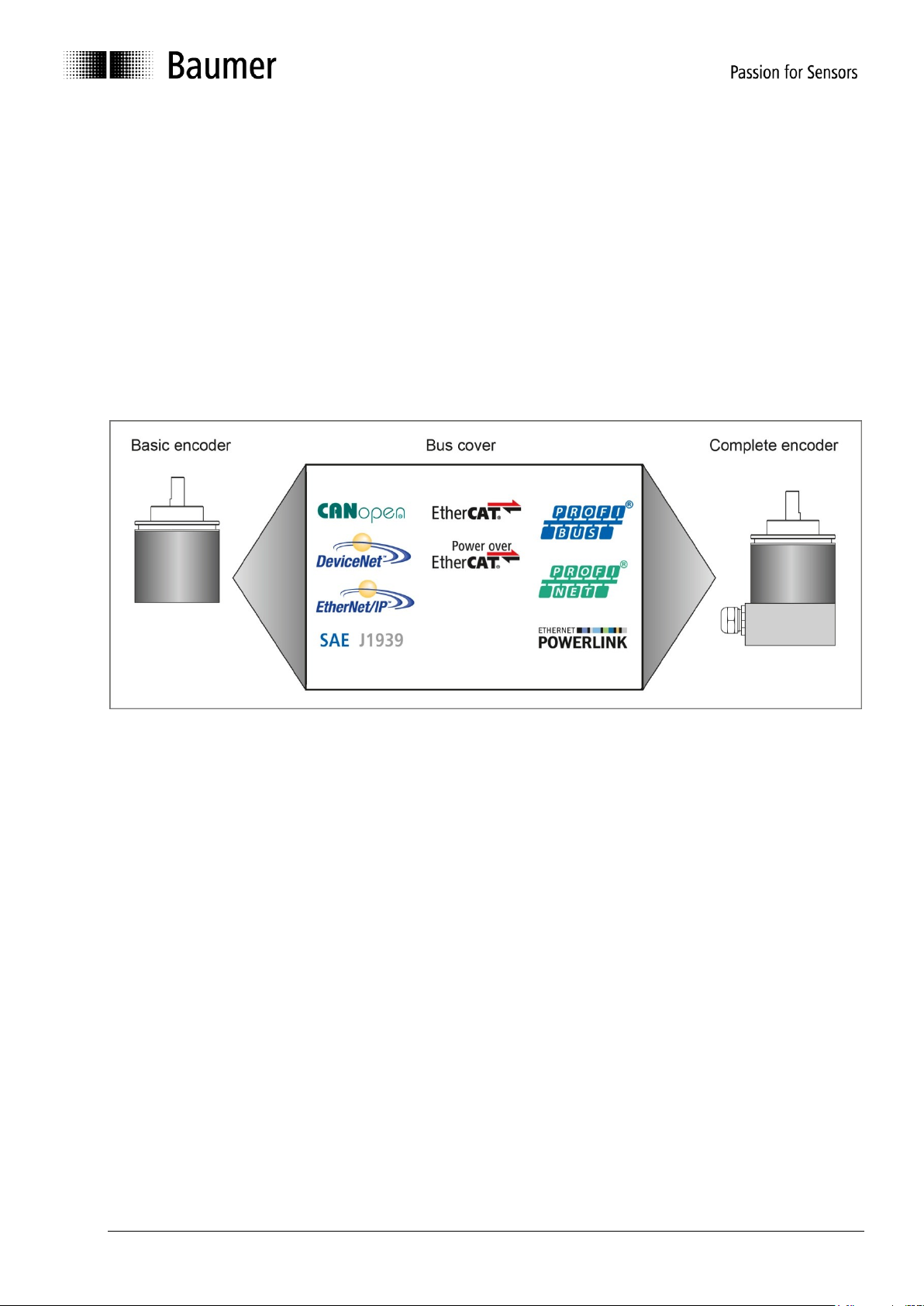
Bus cover – functional principle 3.
The product family architecture is modular. Depending on what is required from the encoder, the basic
encoder and bus covers can be combined at will with the selected bus system.
The basic encoders differ in terms of accuracy, ambient conditions and the utilized sensing principle.
Bus cover
The bus cover accommodates the entire electronics for measured value processing and for Ethernet
communication.
The bus covers differ by the respectively integrated bus interface.
Available bus interfaces: CANopen®, DeviceNet, EtherCAT, Ethernet/IP, Profibus-DP, Profinet, Powerlink,
Power over EtherCAT, SAE J1939, SSI.
All encoders enable parameterization by bus interface.
Functional principle:
Baumer_EtherCAT_PoE_5-00_MA_EN.docx 6/30 www.baumer.com
30.09.14
Page 7

Product
Device
Name
Resolution per turn
0x6001
Number of turns
0x6502
Measuring range
0x6002
Dezimal
Hex
Bit
Dezimal
Hex
Bit
Dezimal
Hex
Bit
BMSx
GCAMW_H
4096
1000
12 1 1 0 4096
1000
12
BMMx
GCMMW_H
4096
1000
12
65536
10000
16
268435456
10000000
28
GXAMW(S)
GXAMW_H
8192
2000
13 1 1 0 8192
2000
13
GXMMW(S)
GXMMW_H
8192
2000
13
65536
10000
16
536870912
20000000
29
GBAMW(S)
GBAMW_H
262144
40000
18 1 1 0 262144
40000
18
GBMMW(S)
GBMMW_H
262144
40000
18
16384
4000
14
4294967296
100000000
32
Encoder operating parameters 4.
Significance of operating parameters
The enabled scaling functionality in CoE is prerequisite for further user-specific parameterization
such as resolution, total measuring range, direction of rotation and preset.
See chapter: SDO (Service Data Objects)
Baumer_EtherCAT_PoE_5-00_MA_EN.docx 7/30 www.baumer.com
30.09.14
Page 8

XML file
PDO Mapping
Product code
Applied in version
BAUMER Group absolute
EtherCAT encoders.xml
10Byte PDO: (default)
4 Byte Position value
2 Byte Warnings
4 Byte System Time/Speed value
or
4Byte PDO: (configurable)
4 Byte Position value
2Byte PDO: (configurable)
2 Byte Position value
20
25
30
V5.00 and up
Value
Data type
Explanation
Position value
UDINT
Current absolute encoder position value. For range-related information
refer to „Encoder operating parameters“
Warnings
UINT
Warnings
Bit 2: 1 Lithium battery power low
Bit 4: 1 Excess shaft turns during power-off
Bit 5: 1 Incorrect encoder configuration
System Time
UDINT
Present system time, resolution in ns, alternative Speed Value DINT
Value
Data type
Explanation
Position value
UDINT
Current absolute encoder position value. For range-related information
refer to „Encoder operating parameters“
Value
Data type
Explanation
Position value
UINT
Current absolute encoder position value. For range-related information
refer to „Encoder operating parameters“
Encoder data 5.
5.1 PDO (Process Data Object)
Depending on the configuration, the encoder will provide the following process data (input data):
10Byte PDO (Default)
4Byte PDO
2Byte PDO
The configuration 4Byte PDO / 2Byte PDO allows for shorter cycle times.
Cycle times are configuration-related, see chapter cycle times
Baumer_EtherCAT_PoE_5-00_MA_EN.docx 8/30 www.baumer.com
30.09.14
Page 9
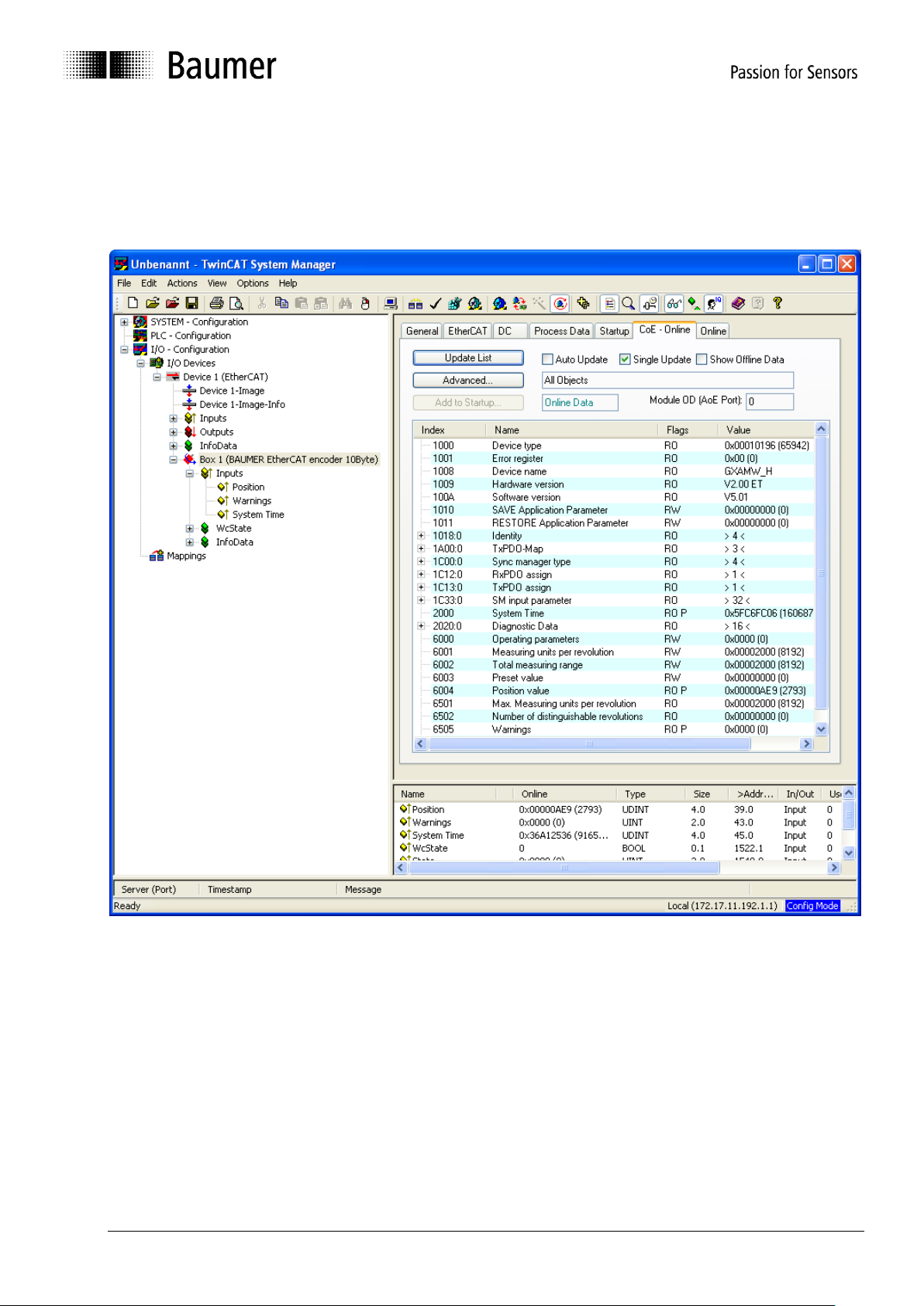
5.2 SDO (Service Data Objects)
SDOs access is in the TwinCAT System under tab CoE - Online (CANopen over EtherCAT).
Since there is a large variety of CANopen device and application profiles they may be applied in EtherCAT
slaves.
EtherCAT encoders provide partial implementation of the CANopen DS406 encoder device profile.
Please consider that every CoE access (mailbox communication) will shortly interrupt generation of encoder
input data for the time of mailbox communication. With short cycle times in Distributed Clocks Mode this may
imply that not in every Sync cycle a new position is detected.
Baumer_EtherCAT_PoE_5-00_MA_EN.docx 9/30 www.baumer.com
30.09.14
Page 10

SubIndex
0
Data type
Unsigned 32
Access
ReadOnly
Default
Multiturn: 0x00020196
Singleturn: 0x00010196h
EEPROM
No
Significance
Information on device profile and device type
Values
SubIndex
0
Data type
VISIBLE_STRING
Access
ReadOnly
Default
According to connected basic encoder
"GXMMW_H","GXAMW_H","GCMMW_H ","GCAMW_H ",
“GBMMW_H ","GBAMW_H "
EEPROM
No
Significance
Device name in ASCII
Values
SubIndex
0
Data type
VISIBLE_STRING
Access
ReadOnly
Default
EEPROM
No
Significance
Hardware version in ASCII
Values
SubIndex
0
Data type
VISIBLE_STRING
Access
ReadOnly
Default
EEPROM
No
Significance
Software version in ASCII
Values
e v a s 0x65
0x76
0x61
0x73
1702257011
Object list Detailed explanations on the most important SDO objects
Object 0x1000 Device Type
Object 0x1008 Device Name
Object 0x1009 Hardware Version
Object 0x100A Manufacturer Software Version
Object 0x1010 SAVE Application Parameter
Object 0x1010 is utilized to save device-specific objects (0x6000..0x6FFF) out of RAM into non-volatile memory
(EEPROM). To prevent inadvertent saving operations the signature „save“ must be written into object 0x1010
Subindex 0.
Signature MSB LSB
ISO 8859 character
hex
dez
Baumer_EtherCAT_PoE_5-00_MA_EN.docx 10/30 www.baumer.com
30.09.14
Page 11

SubIndex
0
Data type
Unsigned 8
Access
ReadOnly
Default
4
EEPROM
No
Significance
Maximum supported subindex
Values
4 = Maximum supported subIndex
SubIndex
1
Data type
Unsigned 32
Access
ReadOnly
Default
Ech
EEPROM
No
Significance
VendorID for Baumer IVO GmbH & Co. KG assigned by CiA
Values
0xEC (in the Internet under www.can-cia.de)
SubIndex
2
Data type
Unsigned 32
Access
ReadOnly
Default
0x0A GXMMW_H ; 0x0B GXAMW_H
0x0C GCMMW_H ; 0x0D GCAMW_H
0x0E GBMMW_H, 0x0F GBAMW_H
EEPROM
No
Significance
Product Code
Values
SubIndex
3
Data type
Unsigned 32
Access
ReadOnly
Default
EEPROM
No
Significance
Revision no.
Values
SubIndex
4
Data type
Unsigned 32
Access
ReadOnly
Default
EEPROM
No
Significance
Serial no.
Values
d a o l 0x64
0x61
0x6F
0x6C
1684107116
Object 0x1011 RESTORE Application Parameter
Object 0x1011 restores ROM default in device-specific objects (0x6000..0x6FFF) both in RAM and EEPROM.
To prevent any inadvertent restore, the signature „load“ must be written in object 0x1011 Subindex 0.
Signature MSB LSB
ISO 8859 character
hex
dez
Object 0x1018 Identity Object
Baumer_EtherCAT_PoE_5-00_MA_EN.docx 11/30 www.baumer.com
30.09.14
Page 12

SubIndex
0
Data type
Unsigned 8
Access
ReadOnly
Default
EEPROM
No
Significance
Maximum supported subindex
Values
3
SubIndex
1
Data type
Unsigned 32
Access
ReadOnly
Default
EEPROM
No
Significance
Position value
Values
0x6004
SubIndex
2
Data type
Unsigned 16
Access
ReadOnly
Default
EEPROM
No
Significance
Warnings
Values
0x6505
SubIndex
3
Data type
Unsigned 32
Access
ReadOnly
Default
0x2000 System time
EEPROM
Yes
Significance
System time, Speed value
Values
0x2000 = System time, 0x6030 = Speed value
Sub
Index
Data Type
Access
Description
Measurand
Values
0
Unsigned 8
ReadOnly
SM Input Parameter
-
Maximum supported Subindex 32
1
Unsigned 16
ReadOnly
Sync Mode
-
0x00 Free Run (not synchronized)
0x03 DC SYNC1, synchronized with
SYNC1 Event
2
Unsigned 32
ReadOnly
Cycle time
Nanoseconds ns
SYNC0/SYNC1 cycle time
3
Unsigned 32
ReadOnly
Shift time
Nanoseconds ns
Shift time from SYNC1 until input data
latch (absolute position)
4
Unsigned 16
ReadOnly
Sync modes
supported
-
0x0009
Free run supported
Synchronous supported
DC SYNC1
Dynamic Cycle times
5
Unsigned 32
ReadOnly
Minimum cycle time
Nanoseconds ns
Minimum cycle time supported
6
Unsigned 32
ReadOnly
Calc and copy time
Nanoseconds ns
Calculation and copy time of process data
out of local memory into SyncManager
Object 0x1A00 TxPDO1 Mapping
Object 0x1C33 SM (Sync Manager) Input Parameter SM3
Baumer_EtherCAT_PoE_5-00_MA_EN.docx 12/30 www.baumer.com
30.09.14
Page 13

SubIndex
0
Data Type
Unsigned 16
Access
ReadWrite
Default
0, scaling OFF, CW, Speed Value readout in steps /s
EEPROM
Yes
Significance
Operating parameters
Values
Bit 0: Direction of rotation
0 CW
1 CCW
Any parameter other than default will only become effective with enabled scaling function (0x6000).
Bit 2: Scaling function ON/OFF
0 scaling disabled, encoder provides raw data (w/o offset)
1 scaling enabled, encoder provides scaled, offset-related position values
Example: Value 0x0004 -> scaling On, CW
Bit 12: Unit for Speed Value readout
0 steps/s
1 rpm
SubIndex
0
Data type
Unsigned 32
Access
ReadWrite
Default
0x2000 = 8192 = 13bit GXxMW_H
0x1000 = 4096 = 12bit GCxMW_H
0x40000 = 262144 = 18bit GBxMW_H, GDxMW_H
EEPROM
Yes
Significance
Optional number of steps per revolution.
Values
1..n.. max. number of steps per revolution (0x6501)
Entries ≠ default values are only effective with enabled scaling function (0x6000).
Device-specific objects
Object Data in this area are hold volatile in RAM after any change. To save in non-volatile EEprom use
object SAVE Application Parameter 0x1010.
Object 0x6000 Operating parameters
User-settable parameters such as resolution, total measuring range, direction of rotation and preset
will not become effective until the scaling function is enabled (bit 2 =1).
See chapter parameterization.
The above parameters will be preliminarily saved in the volatile RAM memory and can optionally be saved
non-volatile in EEProm using object SAVE Application Parameter (0x1010).
Please note that with scaling ON the input data (TxPDO) will be produced much more slowly, i.e. PLC cycle
times for encoder readout should be correspondingly enlarged.
See chapter cycle times.
Object 0x6001 Measuring units per revolution
In general, when writing on this object any previously saved offset (0x6509) will be cleared (value = 0).
Baumer_EtherCAT_PoE_5-00_MA_EN.docx 13/30 www.baumer.com
30.09.14
Page 14

SubIndex
0
Data type
Unsigned 32
Access
ReadWrite
Default
0x20000000 = 536870912 = 29bit GXMMW_H
0x2000 = 8192 = 13bit GXAMW_H
0x10000000 = 268435456= 28bit GCMMW_H
0x1000 = 4096 = 12bit GCAMW_H
0x80000000 = 2147483648 = 31bit ² GBMMW_H
0x40000 = 262144 = 18bit GBAMW_H
EEPROM
Yes
Significance
Total measuring range in steps optionally programmable.
Consequence: Number of revolutions = total measuring range / resolution
The maximum resolution (0x6502) must not be exceeded since otherwise the selected
total resolution range is too wide and will be rejected.
Values
1..n.. max. total measuring range in steps (0x 6502)
Entries ≠ default values are only effective with enabled scaling function (0x6000).
Object 0x6002 Total measuring range
² with disabled scaling 32 bit
Writing in these object will clear any previously saved offset (0x6509, value = 0)
Important for multiturn encoder operation:
Continuous operation will be automatically supported where required.
Consequently, no specific relationship between total measuring range and measuring units per revolution
must be observed in the parameterization.
With enabled continuous operation and during power off, the encoder shaft may be turned up to ¼ of
the maximum permissible turns. Any excess turn may entail void position values which will be
signaled by a warning and call for a new referencing operation.
Non-continuous operation allows for an unlimited number of turns during power-off.
Proceed as below to find out whether your parameterization enables continuous operation:
The „maximum possible number of turns“ provided by the encoder (depending on the configuration:
16 bits = 65536 or 13 bits = 8192) is multiplied by the parameterized measuring units per revolution.
The result is devided by parameterized total measuring range.
A remainder in the result (fractional digits) means continuous operation enabled.
Example: Parameterization with disabled continuous operation:
Max. possible number of turns 65536 (16 bits multiturn)
Measuring units per turn : 3600
Total measuring range 29.491.200 (8192 x 3600)
Calculation: 65536 x 3600 / 29.491.200 = 8 (no remainder)
Example: Parameterization with enabled continuous operation:
Max. possible number of turns 65536 (16 bits multiturn)
Measuring units per turn 3600
Total measuring range 100.000
Calculation: 65536 x 3600 / 100.000 = 2359 remainder 29600
Baumer_EtherCAT_PoE_5-00_MA_EN.docx 14/30 www.baumer.com
30.09.14
Page 15

SubIndex
0
Data type
Unsigned 32
Access
ReadWrite
Default
0
EEPROM
Yes
Significance
Optionally programmable position value.
In this operation an offset value is calculated and saved in object 0x6509.
Values
0..actual total measuring range (0x6002) -1
Entries ≠ default values are only effective with enabled scaling function (0x6000).
SubIndex
0
Data type
Unsigned 32
Access
ReadOnly
Default
EEPROM
No
Significance
Value of actual position in steps
Values
0..actual total measuring range (0x6002) -1
SubIndex
0
Data type
Signed 32
Access
ReadOnly
Default
EEPROM
No
Significance
Current speed value
Values
Unit steps/s or rpm configurable by object 0x6000 Bit 12
SubIndex
0
Data type
Unsigned 8
Access
ReadOnly
Default
2
EEPROM
No
Significance
Largest supported Subindex
Values
2 = largest supported SubIndex
SubIndex
1
Data type
Unsigned 16
Access
ReadOnly
Default
2
EEPROM
No
Significance
Speed Source
Values
2: Speed is calculated out o raw data position
SubIndex
2
Data type
Unsigned 16
Access
Readwrite
Default
100
EEPROM
Yes
Significance
Integration time in ms, to generate the moving average speed value.
To enhance dynamic capabilities select an inferior value.
To improve smoothing select a larger value.
Values
1..1000
Object 0x6003 Preset value
Object 0x6004 Position value
Object 0x6030 Speed value
Object 0x6031 Speed Parameter
Baumer_EtherCAT_PoE_5-00_MA_EN.docx 15/30 www.baumer.com
30.09.14
Page 16

SubIndex
0
Data type
Unsigned 32
Access
ReadOnly
Default
0x2000 = 8192 = 13bit GXxMW_H
0x1000 = 4096 = 12bit GCxMW_H
0x40000 = 262144 = 18bit GBxMW_H, GDxMW_H
EEPROM
No
Significance
Maximum singleturn resolution in steps
Values
SubIndex
0
Data type
Unsigned 32
Access
ReadOnly
Default
0x10000 = 65536= 16bit GXMMW_H
0x10000 = 65536= 16bit GCMMW_H
0x2000 = 8192 = 13bit ² GBMMW_H
EEPROM
No
Significance
Maximum number of revolutions
Values
With singleturn encoders =0, otherwise according to basic encoder
SubIndex
0
Data type
Unsigned 16
Access
ReadOnly
Default
0
EEPROM
No
Significance
Warnings
Values
Multiturn encoder
Bit 2: 1 Lithium battery voltage low
Bit 4: 1 Excess shaft turns during power off
Bit 5: 1 inappropriate sensor configuration
SubIndex
0
Data type
Unsigned 32
Access
ReadOnly
Default
0
EEPROM
Yes
Significance
Value is calculated upon writing on object Preset (0x 6003)
Values
Object 0x6501 Max. measuring units per revolution (max. resolution in steps)
Object 0x6502 Number of distinguishable revolutions
² with disabled scaling 14 bit
Object 0x6505 (Warnings)
Object 0x6509 Offset
Baumer_EtherCAT_PoE_5-00_MA_EN.docx 16/30 www.baumer.com
30.09.14
Page 17

Scaling
Rotation
Value 0x6000
OFF
CW
0x0000
OFF
CCW
0x0001
ON
CW
0x0004
ON
CCW
0x0005
Object 0x6000 Operating parameters
Scaling: ON Bit 2 = 1
Rotation: Bit 0 = 0 CW , 1=CCW
Object 0x6002 Total measuring range
Mutiturn
Object 0x6001 Measuring units per revolution
Saved non-
volatile
Object 0x1010 SAVE
Value :0x65766173
Object 0x6003 Preset,
Referencing
J
J
J
N N N
CW = clockwise = increasing values with
clockwise shaft rotation
CCW = counterclockwise = increasing values
with counterclockwise shaft rotation
Reference: when looking at flange
5.3 Parameterization
Proceed as below for user-specific parameterization of direction of rotation, resolution, total resolution, preset:
Examples: Scaling ON in object 0x6000
Baumer_EtherCAT_PoE_5-00_MA_EN.docx 17/30 www.baumer.com
30.09.14
Page 18

5.4 Free Run Mode (default)
In "Free Run" mode, a local timer interrupt of the application controller will trip the local cycle which in Free
Run is independent of communication cycle and/or master cycle. The encoder will generate the process data
in asynchronous cyclic manner.
Fig.: Wireshark Network session, encoder input data
Baumer_EtherCAT_PoE_5-00_MA_EN.docx 18/30 www.baumer.com
30.09.14
Page 19

5.5 Distributed Clocks Mode
Distributed clocks mode enables exactly the same time with all bus users.
The encoder can be utilized and configurated as reference clock for synchronisation purposes of both other
users and master. Thus a high-precision time base is available throughout the network.
The encoder generates process data synchronously to a Sync Signal.
The local cycle will be tripped once SYNC0/SYNC1 Event has been received. Prior to receiving the next
SYNC0/SYNC1 Event the process data frame must be completely processed by the slave.
5.5.1 Activation Distributed Clocks under TwinCAT
Important:
Enable SYNC0 and SYNC1.
Ever proceed any cycle time modification in the SYNC0 settings only.
Do not alter any SYNC1 settings.
Baumer_EtherCAT_PoE_5-00_MA_EN.docx 19/30 www.baumer.com
30.09.14
Page 20

1C33:2 Cycle time
1C33:5 Minimum Cycle time
1C33:6 Calc and copy time
1C33:3 Shift time time
Input Latch
Sync 0 Event
Sync 0 Event
Sync 1 Event
Sync 1 Event
SSI CLK
SPI SS
Fig.: Local cycle synchronized with SYNC0/SYNC1
Cycle times corresponding to configuration, see chapter Cycle times
Baumer_EtherCAT_PoE_5-00_MA_EN.docx 20/30 www.baumer.com
30.09.14
Page 21

EtherCAT State Machine
The EtherCAT State Machine (ESM) will control the state
of the EtherCAT slave with state-related access and
execution of several functionalities. Specific commands
by the EtherCAT master are required in each state
during slave bootup.
The states of an EtherCAT slave are:
Init
Pre-Operational
Safe-Operational and
Operational
Boot (not supported)
After bootup each EtherCAT slave will be in state Op.
5.6 Network management
The encoder’s State Machine can be switched in the TwinCAT System Manager under tab Online.
Baumer_EtherCAT_PoE_5-00_MA_EN.docx 21/30 www.baumer.com
30.09.14
Page 22

Init
Initial state of EtherCAT slave after switch on. There is neither mailbox nor process data communication. The
SyncManager channels 0 and 1 for mailbox communication are being initialized by the EtherCAT master.
Pre-Operational (Pre-Op)
The EtherCAT slave will verify proper mailbox initialising when changing from Init to Pre-Op. Pre-Op enables
mailbox communication but not process data communication. The EtherCAT master will initialize the
SyncManager channels (up from 2) for the process data, the FMMU channels and PDO mapping or
SyncManager PDO assignment, provided the slave supports configurable mapping.
Furthermore, the process data transmission settings as well as clamp-specific parameterization- other than
default and where appropriate - are transmitted in Pre-Op state
Safe-Operational (Safe-Op)
Upon changing from Pre-Op to Safe-Op, the EtherCAT slave will verify whether the SyncManager channels
for process data communication and the Distributed Clock settings are valid. Prior to confirming Safe-Op, the
slave will copy the current input data into the related DP-RAM areas of the EtherCAT Slave Controller (ESC).
In Safe-Op both mailbox and process data communication are enabled, however the slave will keep its
outputs safe (not relevant to encoder). Cyclic update of input data.
Operational (Op)
Process data and mailbox communication is in Op state.
Cyclic update of input data.
Boot (for firmware update): not supported.
Baumer_EtherCAT_PoE_5-00_MA_EN.docx 22/30 www.baumer.com
30.09.14
Page 23

Terminal assignment and commissioning 6.
6.1 Mechanical mounting
Shaft encoders
Mount encoder housing by help of the mounting holes and three screws (square flange: 4 screws)
provided at flange. Observe thread diameter and depth.
There is an alternative mounting option in any angular position by eccentric fixings, see under
accessories.
Connect drive shaft and encoder shaft by using an appropriate coupling. The shaft ends must not touch
each other. The coupling must equalize any shifts due to temperature as well as mechanical tolerances.
Observe the maximum permitted axial or radial shaft load. For appropriate couplings please refer to
accessories.
Tighten the mounting screws firmly.
Hollow shaft encoder
Clamping ring fixture
Prior to mounting the encoder open the clamping ring completely. Push encoder onto the drive shaft and
tighten the clamping ring firmly.
Encoder torque pin
Slide encoder onto the drive shaft and insert torque pin into the adjusting element provided by customer.
Adjusting element with rubberized spring element
Push the encoder on to the drive shaft and insert the parallel pin into the mounted adjusting element (not
supplied) (with rubberized spring element)
Adjusting bracket
Push the encoder over the drive shaft. Insert the adjusting bracket into the rubberized spring element of
the encoder and fasten the adjusting bracket on the contact surface (not supplied).
Shoulder screw
Push the encoder over the drive shaft and insert the shoulder screw (not supplied) in the rubberized spring
element of the encoder.
Coupling spring
Mount the coupling spring with screws onto the fixing holes of the encoder housing.
Push the encoder over the drive shaft and fasten the coupling spring on the contact surface.
6.2 Electrical connection
Assignment – M12 connector
Follow also the instructions of the respective supplier.
- Press mating connector softly into the plug.
- Turn mating connector carefully until the code mark is interlocking the corresponding space provided by the
plug. Insert bushing completely. Tighten the nut as far as possible.
Exchange bus cover
The bus cover is to be stored and transported whilst in the ESD bag only. The bus cover has to fit the case
tightly and has to be firmly secured by screws.
Remove bus cover
- Unscrew both fixing screws of the bus cover.
- Loosen bus cover carefully and remove it in axial direction.
Plug on bus cover
- Plug the bus cover carefully onto the D-SUB plug of the basic encoder, then push it over the rubber seal.
Avoid the case getting wedged. The bus cover has to fit tightly the basic encoder.
- Tighten both fixing screws firmly and conformable.
- An optimized connection between encoder case and the braiding shield of the supply cable is only achieved
by a complete and close fit of the bus cover onto the basic encoder (interlock).
Baumer_EtherCAT_PoE_5-00_MA_EN.docx 23/30 www.baumer.com
30.09.14
Page 24

4
5 7 3 6 1
2
6.2.1 Initialising under TwinCAT system manager
The included XML file must be copied into the respective directory:
..\TwinCAT\Io\EtherCAT
Start TwinCAT system manager
Then proceed as described below.
EtherCAT devices should appear like in screen below
Baumer_EtherCAT_PoE_5-00_MA_EN.docx 24/30 www.baumer.com
30.09.14
Page 25

Bus cover shaft / blind hollow shaft - EtherCAT
1 x M12 connector (male), a-coded
2 x M12 connector (female), D-coded
Pin
Assignment
Pin
Assignment
1
UB (10...30 VDC)
1
TxD+
2 N.C.
2
RxD+
3 GND
3
TxD-
4 N.C.
4
RxD-
1 x M12 connector (female), D-coded
Pin
Assignment
1
TxD+
2 RxD+
3 TxD-
4
RxD-
60
63
OUT
L/A
IN
Status-Anzei ge
Status di splay
DUO-LED
Li nk/Acti vi ty
Anzeige/displ ay
LED
OUT IN
L/A
6.2.2 Terminal assignment
Bus cover shaft / blind hollow shaft - Power over EtherCAT (PoE)
Baumer_EtherCAT_PoE_5-00_MA_EN.docx 25/30 www.baumer.com
30.09.14
Page 26

RUN State
Status
Description
Category
Off
INIT
The device is in state INIT
Mandatory
Blinking
PRE-OPERATIONAL
The device is in state PRE-OPERATIONAL
Mandatory
Single Flash
SAFE-OPERATIONAL
The device is in state SAFE-OPERATIONAL
Mandatory
On
OPERATIONAL
The device is in state OPERATIONAL
Mandatory
Flickering
INITIALISATION or
BOOTSTRAP
The device is booting and has not yet entered the INIT
state, or the device is in state BOOTSTRAP.Firmware
download operation in progress
Optional
Double Flash
Reserved
Reserved for future use
reserved
Triple Flash
Reserved
Reserved for future use
reserved
Quadruple
Reserved
Reserved for future use
reserved
ERR State
Error
Description
Example
Category
Off
No error
The EtherCAT
communication of the
device is in working
condition
Mandatory
Flickering
Booting Error Booting
Error was detected. INIT
state reached, but
Parameter "Change" in the
AL status register is set to
0x01:change error
Checksum Error in Flash
Memory.
Optional
Blinking
Invalid Configuration
General Configuration Error
State change commanded
by master is impossible due
to register or object settings.
Mandatory
Single Flash
Unsolicited State
Change
Slave device application
has changed the EtherCAT
state autonomously:
Parameter "Change" in the
AL status register is set to
0x01:change/error.
Synchronisation Error,
device enters SafeOperational automatically.
Mandatory
Double Flash
Application Watchdog
Timeout
An application watchdog
timeout has occurred.
Sync Manager Watchdog
timeout
Mandatory
Triple Flash
Reserved
Reserved for future use
Reserved
Quadruple Flash
Reserved
Reserved for future use
Reserved
On
PDI Watchdog
Timeout
A PDI Watchdog timeout
has occurred
Application controller is not
responding any more
Optional
Link
Activity
State of Link/Activity indicator
Yes
No
On
Yes
Yes
Flickering
No
Not applicable
Off
6.3 Display elements
6.3.1 State indicator
The bus cover provides a DUO LED (green/red) operating in line with EtherCAT Indicator Specification V0.91.
DUO-LED green RUN State
DUO-LED red ERR State
6.3.2 Link/Activity indicator
One LED each for input and output.
Note: All LED´s are “off“ if the encoder is under power supply but not yet connected to Ethernet.
Baumer_EtherCAT_PoE_5-00_MA_EN.docx 26/30 www.baumer.com
30.09.14
Page 27

PoE encoder at EK1132 EtherCAT-branch
6.4 Bus cover Power over EtherCAT (PoE)
Based on the IEEE-standard 802.3af, the Baumer EtherCAT encoder with PoE bus cover is interacting as PD
(Powered Device) with a corresponding PSE (Power Sourcing Equipment) module. Signal and power
transmission is by 4-wire standard EtherCAT/Ethernet cable (for example CAT-5). The PSE will identify the
encoder as PD after power on by the procedure specified in IEEE standard 802.3af.
Encoder supply of 48 V must be provided by an auxiliary PSE module (for example Beckhoff EtherCAT
branch EK1132).
Features
- Functionality compliant to standard IEEE Std 802.3af
- Excess temperature protection
- PoE mains unit galvanically insulated
- Hot-Connect feasible (connecting/disconnecting the device during operation)
Technical data
PoE capacity class: 1 (max. 4 W)
PoE supply voltage: 44…57 VDC
Current consumption: 50 mA (48 VDC)
Cable length: max.100 m
Baumer_EtherCAT_PoE_5-00_MA_EN.docx 27/30 www.baumer.com
30.09.14
Page 28

10 Byte PDO (default)
0x1C33:3
Shift time
0x1C33:5
Minimum cycle time
0x1C33:6
Calc and copy time
Basic encoder
Scaling OFF
Scaling ON
Scaling OFF
Scaling ON
Device name
21300
214500
419500
188700
393700
GCAM
41800
234000
413000
185200
364200
GCMM
25000
217000
419000
183000
385000
GXAM
41000
233000
410000
183000
360000
GXMM
33600
228000
416000
185400
373400
GBAM
50600
245000
423000
185400
363400
GBMM
4 Byte PDO
0x1C33:3
Shift time
0x1C33:5
Minimum cycle time
0x1C33:6
Calc and copy time
Basic encoder
Scaling OFF
Scaling ON
Scaling OFF
Scaling ON
Device name
21300
74500
279500
48700
253700
GCAM
41800
92000
271000
43200
222200
GCMM
25000
76000
278000
42000
244000
GXAM
41000
92000
269000
42000
219000
GXMM
33600
86000
274000
43400
231400
GBAM
50600
104000
282000
44400
222400
GBMM
2 Byte PDO
0x1C33:3
Shift time
0x1C33:5
Minimum cycle time
0x1C33:6
Calc and copy time
Basic encoder
Scaling OFF
Scaling ON
Scaling OFF
Scaling ON
Device name
21300
62500
267500
36700
241700
GCAM
41800
85000
264000
36200
215200
GCMM
25000
68000
270000
34000
236000
GXAM
41000
84000
261000
34000
211000
GXMM
33600
78000
266000
35400
223400
GBAM
50600
96000
274000
36400
214400
GBMM
6.5 Cycle times
Cycle times relate to the following settings:
Basic encoder type
Scaling on/off (0x6000 Bit 22)
Configuration 10 byte PDO/ 4 byte PDO/ 2 byte PDO
Scaling ON: 0x6000 22 =1; Scaling OFF: 0x6000 22 =0;
Chart on cycle times All times in ns
Note: Setting 2 byte PDO means input data will be limited to 2 bytes, no matter what the maximum
total encoder resolution is.
Baumer_EtherCAT_PoE_5-00_MA_EN.docx 28/30 www.baumer.com
30.09.14
Page 29

2
Right mouse button
EEProm update
Choose configuration
OK
Wait until EEprom writing cycle has been finalized
1
mark
6.6 Configuration 10 Byte PDO / 4 Byte PDO / 2 Byte PDO by TwinCAT
Default encoder configuration is 10 Byte PDO.
As an option, the encoder configuration may be changed to 4 Byte PDO or 2 Byte PDO to enable shorter
cycle times where appropriate (see chapter cycle times).
Example: How to alter the 10 Byte PDO configuration (default) to 4 Byte PDO
OFF/ON, File new, device search using F5
Baumer_EtherCAT_PoE_5-00_MA_EN.docx 29/30 www.baumer.com
30.09.14
Page 30

Enable Speed Value:
Bit 12 Speed value readout
: 0= steps/s
1= rpm
Integration time 100ms
6.7 Speed Value as an alternative to System Time
The only configuration to enable the speed value (speed transmission) is 10 Byte PDO. To do so, enter value
0x60300020 in TxPDO Mapping object 0x1A00:3. Enter the desired unit for speed value readout in object
0x6000 bit 12 and the integration time in object 0x6031.
Object SAVE Application Parameter (0x1010) will save the parameters in the non-volatile memory.
Example „The Speed Value as an alternative to System Time“ under TwinCAT
Baumer_EtherCAT_PoE_5-00_MA_EN.docx 30/30 www.baumer.com
30.09.14
 Loading...