

Page 1

Operating instructions - Series 09 Ultrasonic Sensors RS-232
Content
1
1.1
2
2.1
2.2
2.3
2.4
3
3.1
3.2
3.3
3.4
3.5
3.6
3.7
3.8
General information .................................................................................................................... 2
General information ...................................................................................................................... 2
Installation ................................................................................................................................... 2
Installation methods and installation suggestions ........................................................................ 2
Mechanical cascading of a number of sensors ............................................................................ 2
Beam columnator .......................................................................................................................... 3
Positioning above containers (Sensors with beam columnator D1) ............................................. 3
The RS-232 interface .................................................................................................................. 4
General notes ............................................................................................................................... 4
Structure of commands ................................................................................................................. 4
Sensor configuration ..................................................................................................................... 5
Factory configurations .................................................................................................................. 5
Commands .................................................................................................................................... 5
Commands explained in detail ...................................................................................................... 8
Trouble shooting ......................................................................................................................... 10
Examples .................................................................................................................................... 10
Bedienungsanleitung_Series09-US_RS232_V1_e.doc 1/11 Baumer Electric AG
26.03.2013 14:43:00/tof Frauenfeld, Switzerland
Page 2
1 General information
1.1 General information
This instruction manual contains information covering installation, initial operation as well as the applicable
communication standards of the Baumer Series 09 ultrasonic sensor family. It supplements the guidelines as
published in the installation instruction sheet which is packed with every sensor shipped.
2 Installation
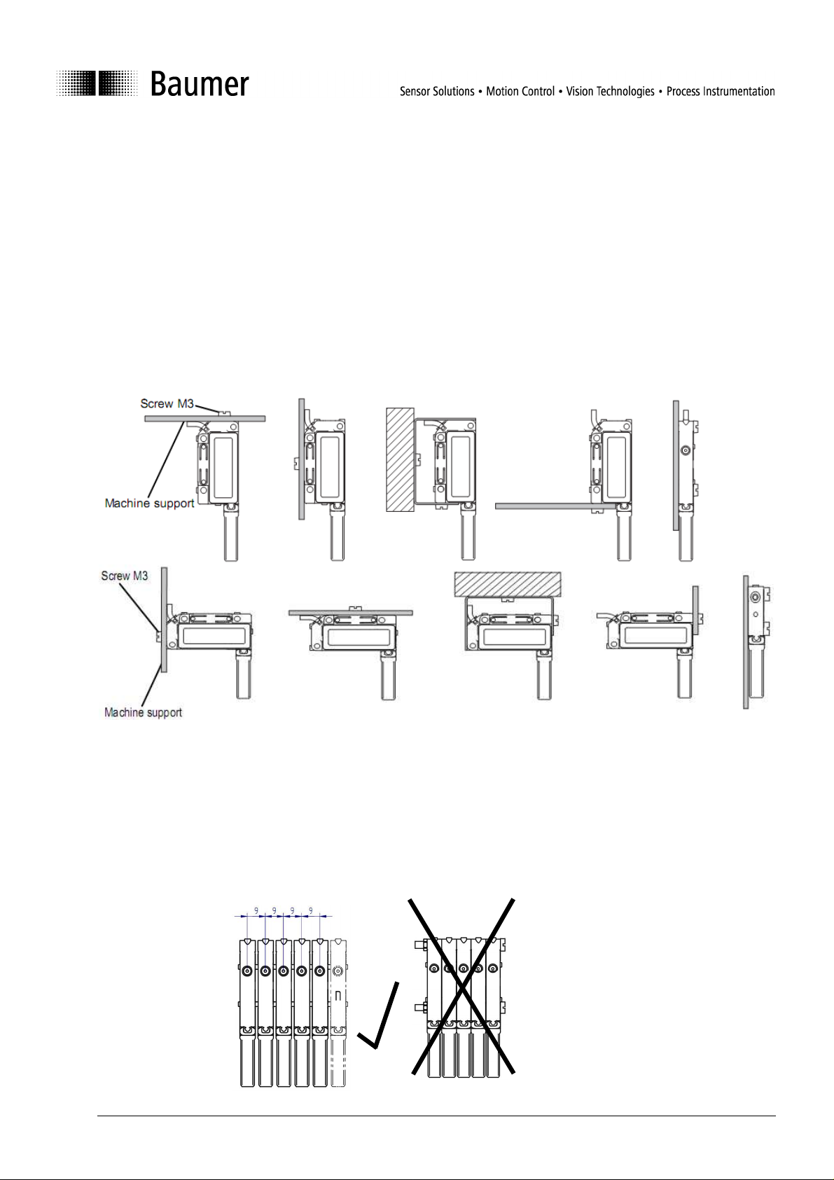
2.1 Installation methods and installation suggestions
2.2 Mechanical cascading of a number of sensors
In case of a number of sensors being installed side by side (cascading) they may not be screwed down
directly touching each other. This is due to the mechanical tolerances of the sensor housings and the
possible danger of transmitting structure-born sound. The sensors must be fixed individually maintaining a
pitch of at least 9 mm.
Cascading of the Series 09 Ultrasonic Sensors without beam columnator is not recommended.
Bedienungsanleitung_Series09-US_RS232_V1_e.doc 2/11 Baumer Electric AG
26.03.2013 14:43:00/tof Frauenfeld, Switzerland
Page 3
2.3 Beam columnator
Never attach a beam columnator to sensors designed for operation without beam columnator only.
Sensors with beam columnator feature extended functions (sensitivity adjustment) which are not available for
sensors without beam columnator.
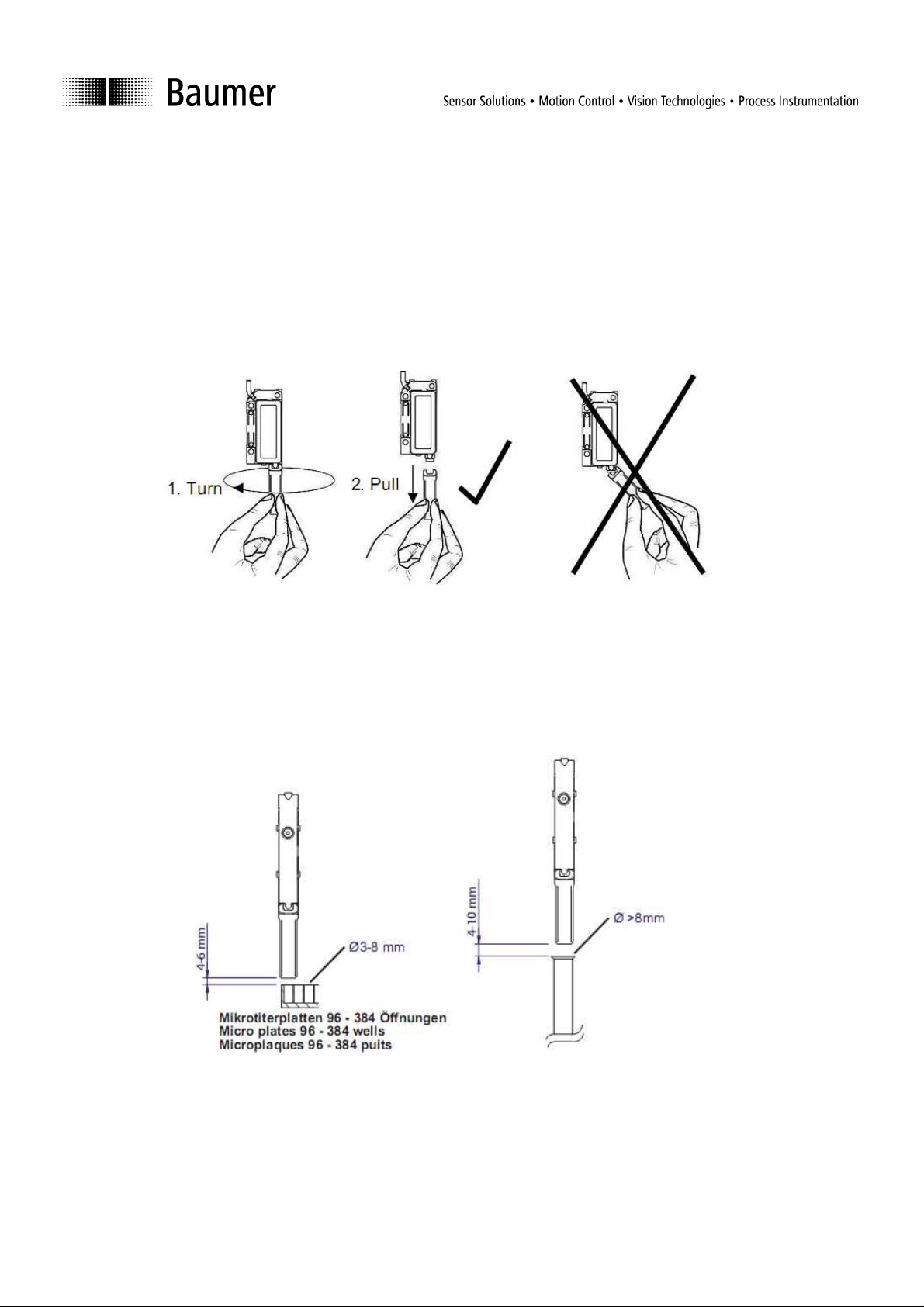
Disassembling the beam columnator
In order to prevent damage to either sensor or beam columnator always turn the beam columnator first (¼
turn) before pulling it off. Never attempt to snap the beam columnator from the sensor without turning it first.
2.4 Positioning above containers (Sensors with beam columnator D1)
When measuring fill levels in micro titration plates or in similarly small containers it is imperative to align the
sensors as accurately as possible above the openings. With reference to applicable mounting distances
following reference values should be applied:
Bedienungsanleitung_Series09-US_RS232_V1_e.doc 3/11 Baumer Electric AG
26.03.2013 14:43:00/tof Frauenfeld, Switzerland
Page 4
3 The RS-232 interface
Start of Frame (SOF)
End of Frame (EOF)
Start of Frame (SOF)
End of Frame (EOF)
3.1
General notes
• Step 1: Setting of the sensitivity mode A-D; Step 2: Teaching of the Scanning range
• In measuring mode: Yellow LED flashing = weak signal received. Conceivable corrective measures: teach
object anew; move object closer to sensor; clean transducer.
• In measuring mode: Red LED on = object within blind range
• Provided the Teach-in sequence cannot be successfully completed the sensor defaults automatically to the
previously saved settings.
• Power must be switched off before connecting the sensors.
• A soiled beam columnator may generate erroneous output signals. Therefore it must be checked from time
to time and cleaned if necessary.
• Via the RS 232 interface measured data can be received and a number of functions are configurable.
• The sensors work with a baud rate of 115’200
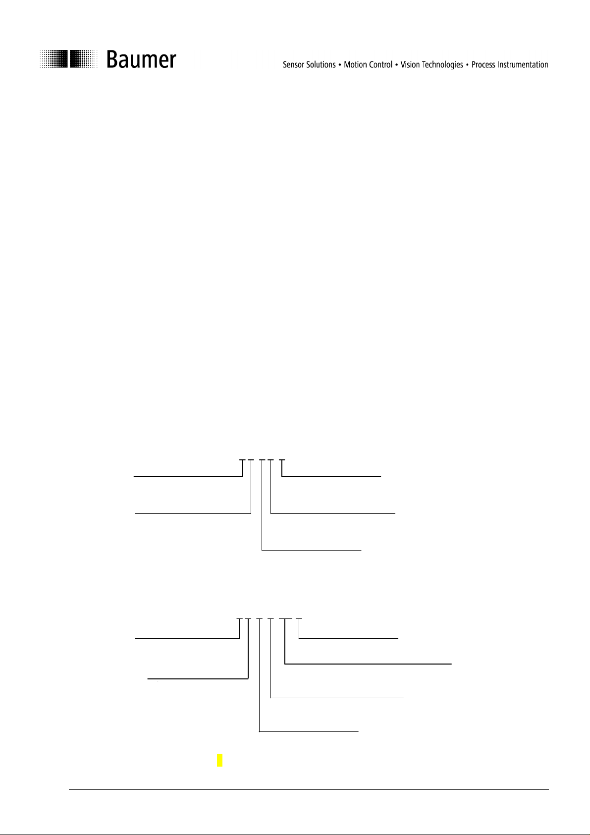
3.2 Structure of commands
All commands consist of ASCII characters only. One character consists of 1 start-Bit, 8 data-Bits and 1 StopBit.
Address
Address „0“ is the broadcast address, which is accepted by every sensor and which must be used when
using RS232.
Telegram sent by the control to the sensor:
NO CHECKSUM!
Telegram (sensor response) sent from the sensor to the control:
Address 1 number 0...8,
for RS232 always 0
{0AB}
X characters
(depends on the command)
Command
Character (A..Z)
{0AB47}
For examples refer to chapter "3.8 Examples".
Address 1 number
0...8, for RS232
Checksum 2 Byte, see appendix
X characters
(depends on command)
Command
Character (A..Z)
Bedienungsanleitung_Series09-US_RS232_V1_e.doc 4/11 Baumer Electric AG
26.03.2013 14:43:00/tof Frauenfeld, Switzerland
Page 5

3.3 Sensor configuration
There are a number of sensor characteristics which can be set via command which have been defined as
configurations.
Configurations are:
• Measuring mode (absolute measurement or relative measurement within the Teach range)
• Output format when using permanent periodical measurement (ASCII or Binary)
• Sensor sensitivity (Sensors with beam columnator)
• Number of averagings
• Temperature compensation on, off
• Teach-in of Sdc and Sde
When leaving production a sensor is pre-configured with its factory settings. These factory settings can be
restored using a special command which overwrites the currently set configuration.
Principle
The functionality of the sensors as well as the output format of the data measured can be set by means of
the configuration commands.
Once the configuration has been carried out the data measured can be retrieved. It is provided according to
the configuration set after every request for data sent. The chosen configuration is stored in a non-volatile
memory and is not lost in a power down situation.
3.4 Factory configurations
Ex factory the sensor is shipped with the following pre-set configurations:
Measuring mode: B (relative)
Output format: A (ASCII)
Sensitivity level: A (Sensors with beam columnator)
Number of averagings: C (4 averagings)
Temperature compensation: 0 (off)
3.5 Commands
(ßß represents the check sum; address 0 is always used in this case)
Name
Reset R {0R} {0RV000019ßß} None This command stops all periodical
Command
Syntax
Sensor
response
Parameter
Comment
data issues.
The sensor responds with its
software version (e.g. 000608)
and with its address (0 in this case)
Bedienungsanleitung_Series09-US_RS232_V1_e.doc 5/11 Baumer Electric AG
26.03.2013 14:43:00/tof Frauenfeld, Switzerland
Page 6

Configuration
Load factory
settings
D {0D} {0Dßß} The Sensor is configured with its
factory settings.
See chapter „Factory
configurations“
Set measuring
mode
A {0AX} {0AXßß} X
A: absolute measurement in 0.1mm
steps
B: relative measurement within the
Teach-range 0…4096
See chapter „Commands explained
in detail“
Set output
format of
permanent
periodical data
output
Set sensor
sensitivity
(Sensors with
beam
columnator)
F {0FX} {0FXßß} X
B {0BX} {0BXßß} X
A: ASCII
B: Binary
See chapter „Commands explained
in detail“
A: Highest sensitivity
Measuring into test tubes
Measuring range: 3…150 mm
B: Second highest sensitivity
Measuring into plates size 96 with
big hole diameter
Measuring range: 3…110 mm
C: Second lowest sensitivity
Measuring into plates size 96 with
small hole diameter
Measuring range: 3…70 mm
D: Lowest sensitivity
Measuring into plates size 384
Measuring range 3…30 mm
See chapter „Commands explained
in detail“
Set number of
averagings
C {0CX} {0CXßß} X
A: not averaged
B: 2
C: 4
D: 8
E: 16
F: 32
G: 64
See chapter „Commands explained
in detail“
Temperature
compensation
on, off
G {0Gx} {0Gxßß} x
0: Temperature compensation off
1: Temperature compensation on
See chapter „Commands explained
in detail“
Teach-in of Sdc X {0X} {0XXßß} X Reads and stores close limit Sdc
A: Teach-in successful
B: No object within measuring
range → basic setting for the
sensitivity the currently set
sensitivity level
Bedienungsanleitung_Series09-US_RS232_V1_e.doc 6/11 Baumer Electric AG
26.03.2013 14:43:00/tof Frauenfeld, Switzerland
Page 7

Teach-in of Sde
Write two Byte
(identification)
Read two Byte
(identification)
Get
configuration
Set
configuration
Single
measurement
Start of
permanent
periodical data
output
Y {0Y} {0YXßß} X Reads and stores far limit Sde
A: Teach-in successful
B: No object within measuring
range → basic setting for the
sensitivity the currently set
sensitivity level
N {0Nxx} {0Nxxßß} xx Write two Bytes with any content.
The sign must not be }.
O {0O} {0Oxxßß} xx Read two Bytes stored
V {0V} {0V……..ßß} Retrieves actually saved
configurations:
Measuring mode (absolute, relative)
Output format (Binary, ASCII)
Sensor sensitivity (Sensors with
beam columnator)
Number of averagings
Temperature compensation on, off
P-code
SW document number
SW version
Identification (2 Byte)
See chapter „Commands explained
in detail“
U {0U……….} {0U……..ßß} Configuration of sensor with a
command:
Measuring mode (absolute, relative)
Output format (Binary, ASCII)
Sensor sensitivity (Sensors with
beam columnator)
Number of averagings
Temperature compensation on, off
See chapter „Commands explained
in detail“
Measuring
M {0M} {0MXYxxxxßß} XYxxxx
X=1→Object within sensing range
X=0→Object not within sensing rg.
Y=1→Echo width big
Y=0→Echo width small
xxxx Measured value in sensor
units (0…4095) or in 0.1mm steps
See chapter „Commands explained
in detail“
P {0P} {0Pßß} Provided ASCII has been selected
the response is identical to the
command „M“
See chapter „Commands explained
in detail“
Bedienungsanleitung_Series09-US_RS232_V1_e.doc 7/11 Baumer Electric AG
26.03.2013 14:43:00/tof Frauenfeld, Switzerland
Page 8

3.6 Commands explained in detail
Check sum
The checksum (CS) represents the sum of all values of the ASCII characters, the last two digits of which are
used.
Example:
Temperature compensation off
Command 0 G 0
Check sum (ASCII values): 48+ 71+ 48 = 167, the two last digits are 67
Command response with Checksum: {0G067}
Measuring mode absolute / relative
Absolute: The sensor refers to the factory calibration and provides absolute measured data in 0.1 mm
steps. Should the object move into the sensor’s blind region (less than 3 mm distance) the output provides
the value 0. In the case of no object being within the measuring range the output shows the value 4095.
Relative always provides the sensor-internal unit: 1 unit = 1/4096 of the configured measuring range (range
of values: 0…4095). When the measuring range has been limited by Teach-in the range of values (0…4095)
applies to the actually used range. The resolution of the measurement has thereby not been improved.
Should the object move into the sensor’s blind region (less than 3 mm distance) the output provides the
value 0. In the case of no object being within the measuring range the output shows the value 4095.
Binary format
The binary format is only used for the permanent periodical data output in order to transmit the data
measured with the maximum data rate. For that reason the binary format is very compact with only a
minimum of overhead.
First Byte Bit 7 is 1 (Mark for start of data string)
Bit6 = 1 → Object within measuring range
Bit6 = 0 → no object within measuring range
Bit 0…Bit 5 are Bit 6..11 of the measured value
Second Byte Bit 7 is 0
Bit6 = 1 → Echo width wide (big signal reserve)
Bit6 = 0 → Echo width narrow (small signal reserve)
Bit 0…Bit 5 are Bit 0…5 of the measured value
Special features of the permanent periodical data output
Data output is stopped by sending the reset command or by switching the sensor off.
Table „Set sensitivity of sensor“ standard values (Sensors with beam columnator)
Sensitivity
A (Standard)
B C D
Size of opening > 8,5 mm 7…8,5 mm 5…7 mm 3…3,5 mm
Mictrotitration plates /
Test tubes etc. 96 Wells 96 Wells 384 Wells
Containers
Measuring range 3…150 mm 3…110 mm 3…70 mm 3…30 mm
Averaging
By averaging a higher number of measurements both the repeat accuracy and the resolution can be
improved. The measuring speed is thereby reduced.
Time per measurement = 7 ms, this corresponds for 8 measurements 8 x 7 ms = 56 ms.
Average algorithm: Floating average
Bedienungsanleitung_Series09-US_RS232_V1_e.doc 8/11 Baumer Electric AG
26.03.2013 14:43:00/tof Frauenfeld, Switzerland
Page 9

Temperature compensation
The temperature compensation has been designed in to compensate the dependance of the speed of sound
on temperature.
temperature are compensated to 2% of So (So = distance from sensor to object). Note: the compensation
becomes active only 15 minutes after the power has been applied. When the temperature compensation is
switched OFF, the sensor measures immediately and correctly at room temperature. Is the environmental
temperature changing a measurement error of 0,18% Sde/K occurs.
Format of the „Get Configuration“ data output
Measuring mode 1 Byte
Output format 1 Byte
Sensor sensitivity 1 Byte (Sensors with beam columnator)
Number of averages 1 Byte
Temperature compensation 1 Byte
P-Code 4 Byte
SW document number 6 Byte
Software version 6 Byte
Identification 2 Byte
Format of „Set Configuration“
Measuring mode 1 Byte
Output format 1 Byte
Sensor sensitivity 1 Byte (Sensors with beam columnator)
Number of averages 1 Byte
Temperature compensation 1 Byte
Provided the temperature compensation is ON changes induced by varying environmental
Bedienungsanleitung_Series09-US_RS232_V1_e.doc 9/11 Baumer Electric AG
26.03.2013 14:43:00/tof Frauenfeld, Switzerland
Page 10

3.7 Trouble shooting
General
The sensors work in a 3-step pattern
1. Waiting for Start of Frame (SOF)
2. Waiting for address or timeout
3. Waiting for End of Frame or timeout
Error conditions
Error according to SOF when:
1. Time between 2 characters exceeds 0.5 s (Timeout)
2. Number of characters does not correspond with the command.
3. Unknown command
4. Command contains wrong parameters
5. Wrong address
Error message
The syntax of an error message is identical to a standard sensor response message
Name
Error message E Faulty
Command
Syntax
command
Sensor
response
message
Parameter
Comment
{0EXßß) X F = Framing error = wrong string
length
T = after SOF or before EOF more
than 0.5s distance between 2
characters
U = Unknown command
P = impermissible parameter
A = Wrong address
Actions in case on an error:
• Sensor is emitting error message
• Sensor is waiting for SOF
• Output provided in case of a false measurement: measured value = 4095 (ASCII), BF 3F (binary)
3.8 Examples
Commands Sent Received Content
Reset {0R} {0RV01000005}
Set factory setting {0D} {0D16}
Set measuring mode {0AB} {0AB79} Relative measurement
Set output data format for
permanent periodical data
issue
Set sensitivity {0BC} {0BC81} Second highest
Set number of averaging {0CC} {0CC82} 4 averaging
Temperature compensation {0G1} {0G168} Temperature comp. ON
{0FA} {0FA83} Set to ASCII
sensitivity
Bedienungsanleitung_Series09-US_RS232_V1_e.doc 10/11 Baumer Electric AG
26.03.2013 14:43:00/tof Frauenfeld, Switzerland
Page 11

Teach-in of SDC {0X} {0XA01} Teach-in successful, the
present object position is
stored as SDC
Teach-in of SDE {0Y} {0YB03} Teach-in not successful,
Teach-in range as
defined in the factory
settings is downloaded
Get Configuration {0V} {0VBADC1A1218110
27010000ab53}
Configuration:
B: relative measurement
A: ASCII for periodical
measurements
D: highest sensitivity
C: 4 times averaged
1: Temperature
compensation ON.
A121: P-Code
811027: SW doc no
010000: SW Version
ab: Identification
52: Check sum
Set configuration {0UABAF0} {0UABAF047} Configuration:
A: absolute
measurement
B: Binary for periodical
measurement
A: lowest sensitivity
F: 32 averagings
0: temperature
compensation OFF
47: Check sum
Write 2 Byte(Identification) {0N01} {0N0123}
Read 2 Byte (Identification) {0O} {0O0124}
Single measurement {0M} {0M11140121}
01 written to the sensor
01 read from the sensor
1: Object within range
1: Echo width big
1401: measured value
Start permanent periodical
data output
{0P} {0P28} This is the first answer,
data follows suit
Error messages (examples)
Error Sent Received Explanation
Wrong address {3M} {0EA82} A = Wrong address
Temperature compensation ON
sent with wrong parameter (3
{0G3} {0EP97} P = impermissible
parameter
instead of 1)
Wrong command {0W} {0EU02} U = unknown command
EOF forgotten {0M {0ET01} T = after SOF before
EOF more than 0.5s
distance between 2
characters
One ‚0’ too many {0M0} {0EF87} F = Framing error =
wrong string length
Bedienungsanleitung_Series09-US_RS232_V1_e.doc 11/11 Baumer Electric AG
26.03.2013 14:43:00/tof Frauenfeld, Switzerland
 Loading...