

Page 1
Assembly & Adjustment
SCATEC – double copy counter
FLDK 110G1903/S42
Page 2

Contents
1 Mechanical Setting & Adjustment..................................................................3
2 Adjustment of the synchronization sensor...................................................5
2.1
2.2
2.3
3 DIP-Switches....................................................................................................8
4 Outputs and LED indicators ...........................................................................9
5 Data sheet....................................................................................................... 10
Version A.......................................................................................................................................6
Version B.......................................................................................................................................7
Checking the adjustment ..............................................................................................................8
20101215_Shortmanual_ScatecDCC_EN.doc 2/10 Baumer Electric AG
15.12.2010 / wej Frauenfeld, Switzerland
Page 3
1 Mechanical Setting & Adjustment
Typically, the Scatec is mounted in an angle of 20 ° to the magazine’s position.
about 20°
Scatec
magazines
direction of
Leading plate
Among the products a leading plate should be installed. These should be mounted close under the gripper
(eg he = 50 mm to 70 mm below the lowest point of the gripper).
The leading plate should have a bright, matte surface (eg matte aluminum plate).
Scatec
Holding point
transportion
(ill. 1)
gripper
magazines
Leading plate
20101215_Shortmanual_ScatecDCC_EN.doc 3/10 Baumer Electric AG
15.12.2010 / wej Frauenfeld, Switzerland
he
(ill. 2)
Page 4

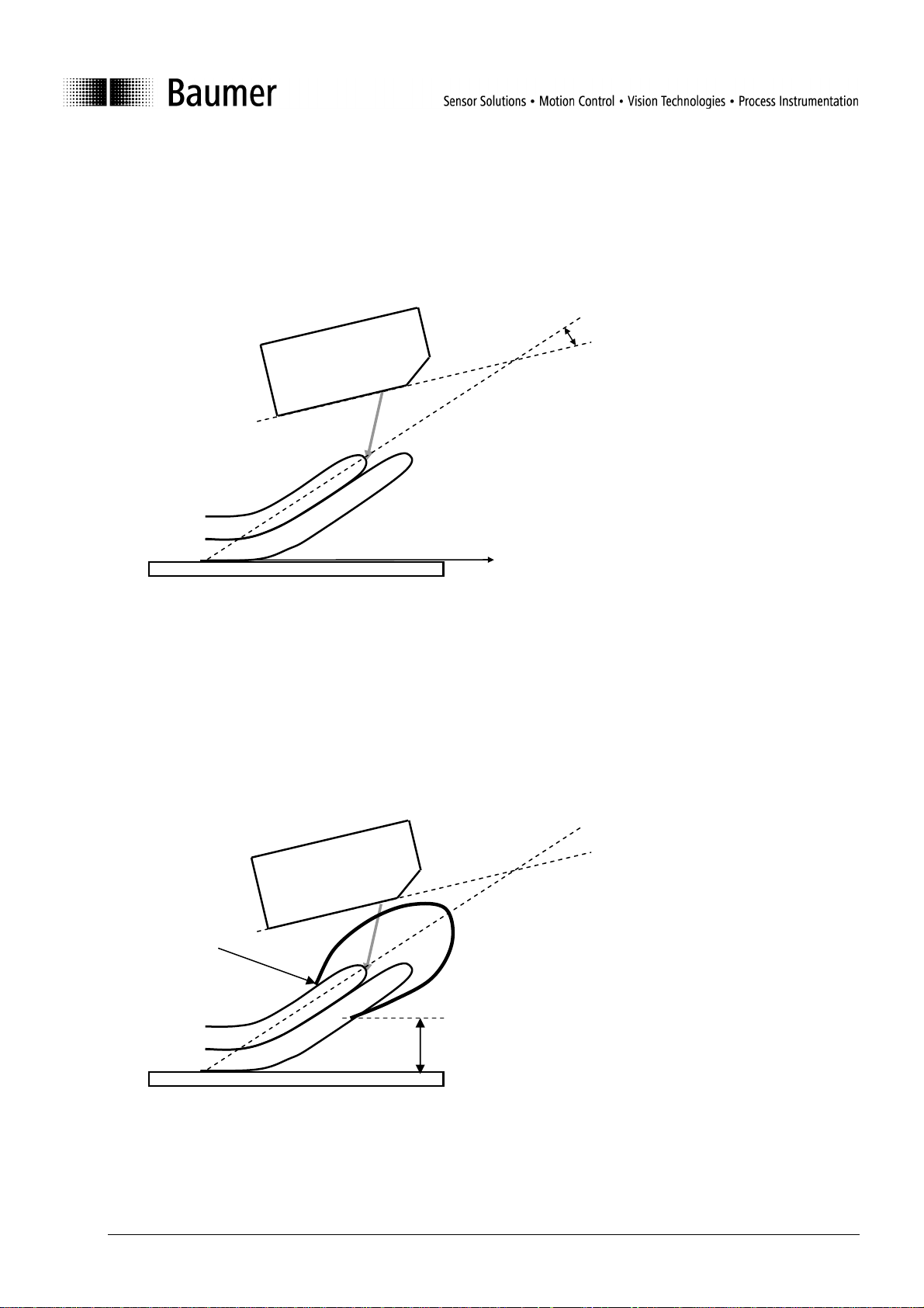
Position of Scatec or mounting angle of the Scatec is set that the laser spot hits the magazines 10 mm (a)
h
a
outside of the gripper. The angle of the Scatec to the vertical (gripper) has not to be greater than 20°.
< 20°
Scatec
gripper
magazine
(ill. 3)
For the best result, the nominal mounting height (h) of the Scatec is 70 mm.
Scatec
(ill. 4)
20101215_Shortmanual_ScatecDCC_EN.doc 4/10 Baumer Electric AG
15.12.2010 / wej Frauenfeld, Switzerland
Page 5

2 Adjustment of the synchronization sensor
The synchronization sensor has to detect each gripper for synchronizing the Scatec. Per gripper the
synchronization sensor only sends one puls to the Scatec.
Examples:
Synchronization
Sensor
The synchronization
sensor detects the metal
part off the wheels
The synchronization
sensor detects the metal
part off the gripper
20101215_Shortmanual_ScatecDCC_EN.doc 5/10 Baumer Electric AG
15.12.2010 / wej Frauenfeld, Switzerland
Page 6

2.1 Version A
Situation:
Position of Scatec is fixed
The synchronization sensor can be moved along the conveyor
Testobjects:
put bright products in gripper
Adjustment:
Move the gripper slowly and stop it when the laser spot lies about 5 mm (b) behind the holding point.
Now move the synchronization sensor along the canveyor in transport direction until the sensor switch ON.
Scatec
Holding point
magazines
Leading plate
gripper
direction of
transport
b
20101215_Shortmanual_ScatecDCC_EN.doc 6/10 Baumer Electric AG
15.12.2010 / wej Frauenfeld, Switzerland
Page 7

2.2 Version B
Situation:
Scatec can be moved along the conveyor
Position of the synchronization sensor is fixed
Test objects:
Put bright products in gripper
Adjustment:
Move the gripper slowly and stop immediately when the synchronization sensor switchs ON.
Adjust the position of the Scatec along the conveyor until the laser spot lies about 5 mm (b) behind the
holding point. Behind the gripper means, that the light spot is lower than the holding point. . The optimum
setting accuracy is + / - 5 mm.
Holding point
magazines
Leading plate
Scatec
gripper
direction of
transport
b
20101215_Shortmanual_ScatecDCC_EN.doc 7/10 Baumer Electric AG
15.12.2010 / wej Frauenfeld, Switzerland
Page 8

2.3 Checking the adjustment
In normal use with magazines in the gripper the functional LED has not to blink.
100%
85%
15%
Signal from
synchronization sensor
Signal from magazin
Signal from magazin
Signal from magazin
It is ok.
green LED flashing: Position to close
orange LED flashing: Position to fare away
3 DIP-Switches
Parameter Dip-Switch Position Value Remark to dead time
Inactive 15% if DIP 3 = ON
Double copy counting
Active 7% if DIP 3 = ON
Pulse
Counting signal output
Synchronous
Minimal 1%
Dead time
Maximal Defined by DIP 1
Maximal
Sensitivity
Reduced
20101215_Shortmanual_ScatecDCC_EN.doc 8/10 Baumer Electric AG
15.12.2010 / wej Frauenfeld, Switzerland
Page 9

4 Outputs and LED indicators
Output 1: switches ON with 1 or 2 copies
Output 2 switches ON with more than 2 copies
Remark:
Output 1 and 2 will be updated with the next following pulse of the synchronization sensor if synchronous
counting signal output (DIP 2) is chosen.
Synchronization signal
Counting
signal output
synchron
outputs
Pulse
synchron
Double copy
counting
active
inactive
active
inactive
Copies
LED / output signal
Out 1
Out 2
Out 1
Out 2
Out 1
Out 2
Edge
LED
Edge
LED
off
off green orange orange
0
off
off
1
2 3.
green
orange red
Pulse
LEDs
In case of too low supply voltage the functional and edge LED is orange
20101215_Shortmanual_ScatecDCC_EN.doc 9/10 Baumer Electric AG
15.12.2010 / wej Frauenfeld, Switzerland
Edge
LED
Functional
LED
Orange as long the Scatec detects an edge
Green: normal Situation
Orange: special setup via ScaDiag
Green blinking: position of magazines to close
Orange blinking: Position of magazines to fare away
Page 10

5 Data sheet
SCATEC – double copy counter FLDK 110G1903/S42
Dimension drawing
General data
Measuring distance sd 0 … 120 mm
Optimum operating distance 70 mm
Object speed < 5 m/sec
Sensitivity Single sheet / edge thickness
0.25 mm
Synch. Input Yes
Measuring point Visible red laser line 2 mm
Light source Pulsed red laser diode
Wave length 650 nm
Laser class 2
Edge indicator LED yellow
Power on indicator LED green
Electrical data
Voltage supply range +Vs 10 … 30 VDC
Power consumption < 2 W
Output circuit 2 x push pull
Short circuit protection Yes
Reverse polarity protection Yes
Synch. Input PNP
Mechanical data
Type Rectangular
Housing material PA 6
Connector base DIN 45326, 8 pin and M8
Front (optics) glass
Ambient conditions
Operating temperature 0 … +50°C
Protection class IP 54
Photo
Connection diagram
Connector M16 / S42
1 synch. +
2 voltage supply +Vs
3 serial interface TxD
4 GND (for synch.)
5 serial interface RxD
6 output 1
7 GND
8 output 2
Connector M8 / S35
1 voltage supply +Vs
3 GND
4 synch. +
20101215_Shortmanual_ScatecDCC_EN.doc 10/10 Baumer Electric AG
15.12.2010 / wej Frauenfeld, Switzerland
 Loading...