

Page 1
SCATEC-2
Laser Copy Counter
FLDK 110G1003/S14
FLDK 110G1003/S42
FLDK 110C1003/S42
FLDK 110G1005/S14
FLDK 110G1005/S42
FLDK 110G1006/S14
FLDK 110x10/xxxxxx
User manual
Manual SCATEC-2 2 Baumer Electric AG
Version 2011-05
www.baumer.com
Frauenfeld, Switzerland
General notes
Rules for proper
usage
This product represents a precision measuring device which has been
designed for the detection of objects and parts. It generates and provides
measured values issued as electrical signals for following systems.
Unless this product has not been specifically marked it may not be used in
hazardous areas.
Set-up
Installation, mounting and adjustment of this product may only be executed
by skilled employees.
Installation
Only mounting devices and accessories specifically provided for this product
may be used for installation.
Unused outputs may not be connected. Unused strands of hard-wired
sensors must be isolated. Do not exceed the maximum permissible bending
radius of the cable. Before connecting the product electrically the system
must be powered down.
Where screened cables are mandatory, they have to be used in order to
assure EMI protection. When assembling connectors and screened cables
at customer site the screen of the cable must be linked to the connector
housing via a large contact area.
Page 2
Manual SCATEC-2 3 Baumer Electric AG
Version 2011-05
www.baumer.com
Frauenfeld, Switzerland
0 Table of Contents
1. Safety information and Certifications
2. Introduction
3. Principle of operation
4. Part identification
5. Terms and definitions
6. Signal sequence
7. Installation
8. Adjustments
9. Instructions for use
10. Specifications
11. Accessories
12. Maintenance
13. Troubleshooting
14. Varying data for customized FLDK 110x10/xxxxxx
FLDK 110x10/xxxxxx
Check section 14 for data
and information varying
from the standard manual !
Manual SCATEC-2 4 Baumer Electric AG
Version 2011-05
www.baumer.com
Frauenfeld, Switzerland
1 Safety information and Certifications
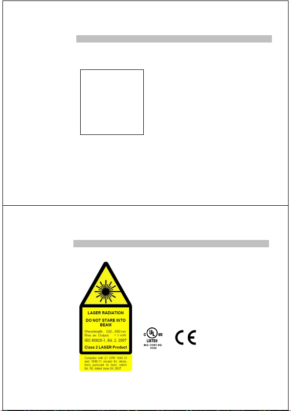
The laser diode installed in the SCATEC-2 emits visible red light.
This laser belongs to the Class 2 laser standard specified by the
IEC 60825-1 / 2007.
Avoid looking directly into the beam for long periods. Brief
irradiation of the eye (0.25 sec) that can occur during an
accidental glance is not regarded to be dangerous.
However, the laser should not be aimed deliberately at people. The
laser beam should also be blocked at the end of its intended path.
Scatec-2 complies with the following safety standards:
Complies with 21CFR 1040.10 and 1040.11 except for deviations
pursuant to laser notice No.50, dated June 24, 2007
Page 3
Manual SCATEC-2 5 Baumer Electric AG
Version 2011-05
www.baumer.com
Frauenfeld, Switzerland
2 Introduction
SCATEC-2 has the same key feature as all the other sensors from the SCATEC family: The capability
of non-contact detection of object edges. SCATEC is the sensor of choice when it comes to detect flat
objects conveyed in an overlapping stream or individually. The sensors in the SCATEC family were
developed and highly optimized particularly with regard to the specific demands of non-contact counting
of overlapping paper sheets and newspapers. Therefore the printing industry will be the ideal area of
application for the SCATEC.
Generally speaking a SCATEC sensor reacts to an edge facing the sensor’s laser beam. If the laser
beam strikes such an edge, SCATEC responds with an electrical output pulse of fixed duration.
However, built-in software allows the sensor among other things to suppress the reaction to certain
edges which were identified by the sensor as “false edges”. Therefore, SCATEC-2 makes it possible to
count newspapers to the highest degree of accuracy even at high conveyor speed.
Within the SCATEC family, the SCATEC-2 is characterized by the following properties:
(For details see specifications of the individual Scatec-2 types.)
• counts edges from a thickness of 0.2 mm and greater
• optimum working distance: 40 mm or 100 mm
• intelligent false pulse suppression
• parameter setting by means of DIP-switches
• counting rate up to 600,000 copies per hour
• with interface for remote control and data analysis
Manual SCATEC-2 6 Baumer Electric AG
Version 2011-05
www.baumer.com
Frauenfeld, Switzerland
3 Principle of operation
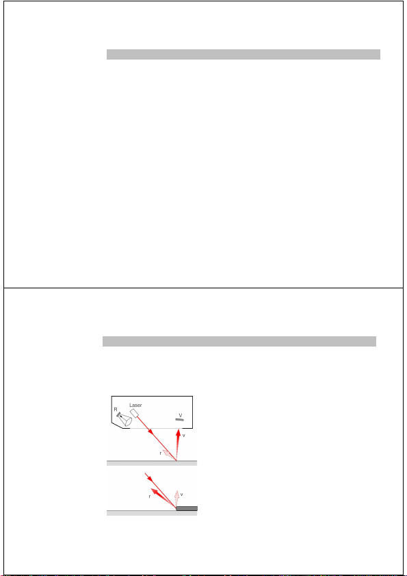
Described simply, the SCATEC-2 consists of a laser light source and two photodetectors. The beam is
aimed diagonally at the objects to be detected. Photodetector R is located close to the laser light source
and photodetector V a little further away. The sensor measures the ratio between signal v (light
scattered forward) and signal r (light scattered backward).
The ratio v/r differs widely depending whether the beam strikes on a flat surface or on an edge. When
an edge moves into the laser beam, the direct line of sight from detector V to the point of contact of the
laser is obstructed, which reduces signal v, and the edge
also increases the backward scattering, causing signal r to
increase. Both effects cause ratio v/r to become
substantially smaller than with a flat surface. If ratio v/r falls
below a specific level, the sensor interprets this as an edge.
This principle of operation clearly demonstrates that:
• The orientation of the object to the beam is significant.
An edge facing towards the beam creates a small ratio
v/r, in contrast to an edge facing away from the beam.
• Edge detection is independent of the color, as only the
ratio of the light intensities and not the absolute value
is used for detection.
Page 4
Manual SCATEC-2 7 Baumer Electric AG
Version 2011-05
www.baumer.com
Frauenfeld, Switzerland
4 Part identification
Edge-LED (yellow)
Sensor plug
Front window
Alignment aid
Lower edge of sensor
DIP-switches
DIP-switch cover
with screw
DIP-switches
O-ring
Power-LED (green)
Connector : .../S42
.../S14
Manual SCATEC-2 8 Baumer Electric AG
Version 2011-05
www.baumer.com
Frauenfeld, Switzerland
5 Terms and definitions
For reference, the terms defined in this section are used throughout the manual.
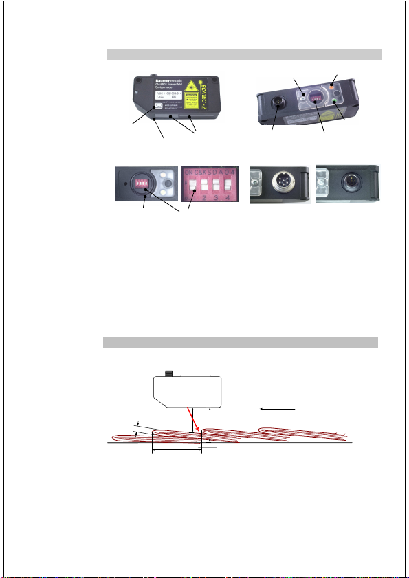
Conveying plane
k
Front edge
Tail edge
d
Beam blocker
a
h
Running
direction
Mounting height: h Distance between the lower edge of the sensor and the conveying
plane.
Working plane The edge lies on the working plane. With thick overlapping copies, the
working plane is slightly higher than the top of the conveying plane on
which the copies are transported. Distance d is measured vertically to
the lower edge of the sensor.
Working distance: d Distance between the lower edge of the sensor and the working plane.
Page 5
Manual SCATEC-2 9 Baumer Electric AG
Version 2011-05
www.baumer.com
Frauenfeld, Switzerland
Overlap: a Distance between two successive edges, measured along the
conveying plane. (Also referred to as the object spacing.)
Edge thickness: k Thickness of the copy at the point where the edge is to be detected.
Front edge The edge of an object facing the laser beam. Front edges are detected
by the sensor.
Tail edge The edge of an object facing away from the laser beam. Tail edges are
not detected by the sensor unless they are pointing upwards.
Running direction The preferred running direction (front edges leading) is indicated. The
opposite direction is also permitted by the SCATEC-2.
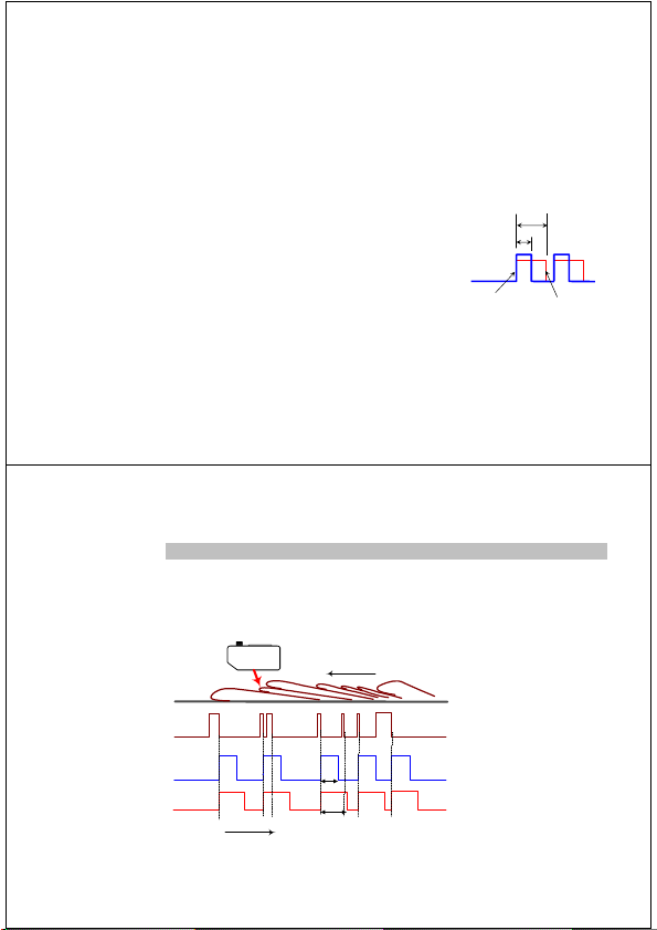
Dead time t The sensor responds to an edge with an output pulse with length p.
The dead time begins when the
pulse is issued. The sensor can
only issue the next pulse after
both the dead time t and the
output pulse p have expired. This
means: an edge detected by the
beam while still either the dead
time t or the the output pulse p is
on does not initiate an output
pulse.
False pulse Output pulse generated by an edge which should not be counted.
Output pulse
Dead time
p
Manual SCATEC-2 10 Baumer Electric AG
Version 2011-05
www.baumer.com
Frauenfeld, Switzerland
6 Signal sequence
The yellow edge indicator LED lights as long as an edge is located in the beam. The output pulse is
issued at the end of the edge. The dead time begins when the output pulse is issued. During the dead
time and when issuing the pulse, the SCATEC-2 is inactive, i.e. an edge ending during the dead time or
the pulse issue of the previous edge will not initiate an output pulse. Therefore, the next output pulse
can only be issued after the dead time has expired and the output pulse has been issued.
yellow edge-LED
output pulse
(pulse length: p)
dead time
(period: t )
Running direction
on
off
high
low
on
off
time
t
p
Page 6
Manual SCATEC-2 11 Baumer Electric AG
Version 2011-05
www.baumer.com
Frauenfeld, Switzerland
7 Installation
7.1 Electrical connection
Make the electrical connections as specified in Sections 10.2 Electrical data and 10.3 Pin assignement.
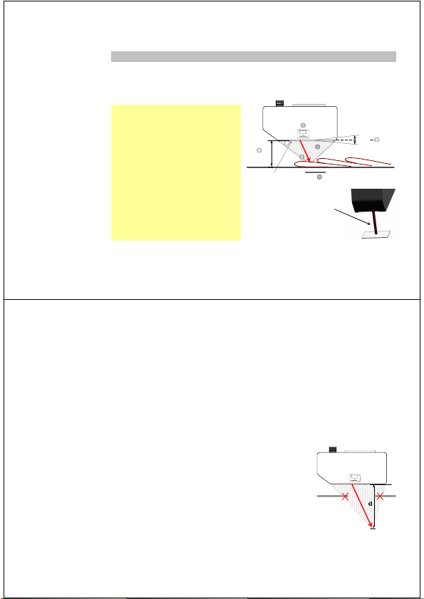
7.2 Mounting
(1) Mount the sensor at the nominal working
distance h (+/-3 mm) with the front
window parallel to the conveying plane.
(2) Adjust the sensor so that the laser beam
is aimed towards the edges to be
counted. When mounted correctly, the
overlap of the copies is facing in the
same direction as indicated in the
alignment aid. Note: the laser beam is
focused into a line which must be aligned
in parallel to the edge to be detected!
(3) Block the laser beam after the objects
whenever possible.
(4) Keep the window clean (remove any
fingerprints after mounting!).
(5) A direct line of sight from the laser impact
point to the entire front window must be
ensured.
Line focus perpendicular to
the
Scatec
housing
Beam blocker
+/- 3°
1
3
2
1
2
Clean window
4
5
Manual SCATEC-2 12 Baumer Electric AG
Version 2011-05
www.baumer.com
Frauenfeld, Switzerland
Nominal working distance h FLDK 110x1003/Sxx 40 mm above the conveyor belt
FLDK 110x1005/Sxx 100 mm above the conveyor belt
FLDK 110x1006/Sxx
The resolution is dependent on the distance. The highest resolution is
achieved at the nominal working distance. (See also Section 10.6
Specific application data)
Angular tolerance max. +/- 3°
Overlap orientation The copies are counted when the edge facing the laser beam moves
through the beam. If an edge faces away from the beam, it is not
detected. Tail edges are therefore not counted unless they face upwards.
Running direction The SCATEC-2 permits both running directions. The edges facing the
laser beam (front edges) are detected by the sensor regardless of the
running direction.
Front window The direct line of sight from the impact
point of the laser to the entire front window
must not be obstructed by any hardware in
a distance range
d = 0 – 80 mm FLDK 110x1003/Sxx
d = 0 – 120 mm FLDK 110x1005/Sxx
FLDK 110x1006/Sxx
If mountings or other components are close
to this zone for any reason, you should
consult a technician from Baumer Electric
AG.
Page 7

Manual SCATEC-2 13 Baumer Electric AG
Version 2011-05
www.baumer.com
Frauenfeld, Switzerland
7.3 Beam blocker
Uncontrolled reflections of the laser beam can cause malfunctioning of the sensor or disturb people.
Therefore, a beam blocker should be fitted whenever possible to block the beam when there is no target
present. A flat surface (at least approx. 25x25 mm) made of a matte, non-reflecting material is
recommended as the beam blocker. The beam blocker must be mounted parallel to the sensor. The
yellow edge indicator LED must not light when the laser beam strikes the beam blocker.
7.4 Cleaning the front window
Fingerprints, dust and other forms of dirt on the front window can impair the function of the sensor.
There is a high risk of accidentially leaving fingerprints on the windows when mounting the sensor.
Make sure that after the mounting the front windows are cleaned! It is normally sufficient to wipe the
glass pane dry with a clean (!), soft cloth. Alcohol may be used for heavier soiling.
7.5 Checklist for correct mounting
When the SCATEC-2 is mounted correctly:
• the green power LED lights as long as the electrical supply is connected
• the product overlap faces in the same direction as indicated on the sensor label
• the laser beam is focused on the conveying plane into a line about 2 (3) mm long
• the laser line focus must be aligned in parallel to the edges to be detected
• the yellow edge indicator LED does not light when the laser beam strikes the beam blocker
• the yellow edge indicator LED lights as long as an edge is located in the beam
• the front windows are clean
Manual SCATEC-2 14 Baumer Electric AG
Version 2011-05
www.baumer.com
Frauenfeld, Switzerland
8 Adjustments
With the SCATEC-2, the following parameters and operating modes can be adjusted:
• Output pulse length
• False pulse suppression
• Sensitivity
The parameters can be adjusted in two ways: via the interface or using DIP switches.
Parameter setting through the interface allows continuous choice of the parameters, whereas a
selection is made from a defined set when the parameters are set with the DIP switches. Parameter
setting through the interface using a computer is described in the user manual for the software package
ScaDiag.
Note: The sensor is only in DIP switch mode when the power LED lights green.
• If the power LED lights yellow instead of green, the parameters of the sensor have been set
through the interface. In this case, the DIP switches are inactive on the sensor and their settings
are irrelevant. The sensor can be reset to DIP switch mode, in which the parameters are defined
by the DIP switches, in two ways.
a) Through the interface (see user manual for the software package ScaDiag).
b) By setting the DIP switches in the following sequence:
1. Set all switches to OFF (at least one must have been ON previously)
2. Set all switches to ON within 16 seconds
3. Set all switches back to OFF within 16 seconds
4. The power LED should then light green after a brief delay. The parameters of the
sensor can then be adjusted with the DIP switches
• To prevent the loss of the DIP switch cover screw, do not fully remove it from the cover. The screw
is retained by the cover.
Page 8

Manual SCATEC-2 15 Baumer Electric AG
Version 2011-05
www.baumer.com
Frauenfeld, Switzerland
DIP-switch settings:
The effects of the various DIP-switch settings are
described in Section 9 Instructions for use below
FLDK 110x1003/Sxx
FLDK 110x1005/Sxx FLDK 110x1006/Sxx
Factory settings
Parameter
DIPswitch
Setting Value
off / off 5 ms
off / on 10 ms
on / off 15 ms
Output pulse
length
1 / 2
on / on 20 ms
off inactive False pulse
suppression
3
on Active
on reduced
Sensitivity 4
off maximum
Parameter
DIPswitch
Setting Value
off leading Running
direction
1
on trailing
off 5 ms Output pulse
length
2
on 10 ms
off inactive False pulse
suppression
3
on active
on reduced
Sensitivity 4
off maximum
Factory setting
o Do remount the cover after having set the
DIP-switch to avoid intrusion of dust
Manual SCATEC-2 16 Baumer Electric AG
Version 2011-05
www.baumer.com
Frauenfeld, Switzerland
9 Instructions for use
9.1 Output pulse length and maximum counting rate
On the one hand, the duration of an output pulse must be long enough so that the customer’s control
system can process it. On the other hand, the length of the output pulse limits the maximum counting
rate. Because output pulses must not overlap, the interval between edges must be at least as long as
one output pulse length. If the interval is shorter, then this edge will be suppressed meaning that the
edge will not initiate an output pulse.
The following figure illustrates how every other edge is suppressed because of a too long of an output
pulse length.
amber edge-LED
output pulse
pulse length p < interval a
on
off
high
low
time
p
high
low
output pulse
pulse length p > interval a
some edges are suppressed!
a
p
a
Scatec-2
Page 9

Manual SCATEC-2 17 Baumer Electric AG
Version 2011-05
www.baumer.com
Frauenfeld, Switzerland
A helpful rule of thumb is: Output pulse length p in milliseconds must be shorter than 1.2 million
divided by the production rate given in copies per hour
The theoretical maximum production rate where output pulses follow each other without any gap in
between is 3 times higher than the recommended value given by the rule of thumb. Exceeding the
recommended value of the production rate increases the risk of missing edges due to irregular intervals
between copies.
The following table lists the recommended maximum production rate for some values of the output
pulse length.
set
output pulse length
[milliseconds]
recommended maximum
production rate
[copies/hour]
1 1,200,000
2 600,000
5 240,000
10 120,000
15 80,000
20 60,000
If suddenly the Scatec starts to miss copies while the production rate is run up, the reason very often is
too short an output pulse length for the actual production rate in combination with fluctuations of the
interval between copies.
Manual SCATEC-2 18 Baumer Electric AG
Version 2011-05
www.baumer.com
Frauenfeld, Switzerland
9.2 False pulse suppression
It is generally recommended that the SCATEC-2 should be operated with the false pulse suppression
feature active. In this way, multiple pulses caused by thicker copies (newspapers, folded cardboard
boxes etc.) or by a small crease at the edge can be suppressed.
The false pulse suppression feature ensures that no further pulses can be issued when an output pulse
is active and during the dead time. Activating the false pulse suppression feature causes the sensor to
automatically initiate a dead time when each pulse is issued, whose duration is 18% of the average
overlap spacing. If an output pulse is followed by another in less than about 1/6 of the current average
overlap spacing time, this pulse is suppressed, as it lies within the dead time of the preceding pulse.
The average overlap spacing time is constantly recalculated automatically by the SCATEC-2. This
ensures that the dead time is adjusted if the conveying speed changes. In certain cases, one edge may
be suppressed if the conveying speed is very quickly accelerated, whereas one false impulse may not
be suppressed during very fast braking. However, gaps in the overlapping stream caused when
individual copies are removed or when the overlapping stream is briefly diverted have no effect. The
false pulse suppression feature has no effect on the maximum counting rate as the dead time is
shortened as the counting frequency rises and can even become shorter than the output pulse length.
This occurs when the average copy spacing time becomes less than 6 times of the output pulse length.
Ideally, the sensor would not issue further pulses after a valid output pulse for a specific length, as the
typical distance between two edges is often known regardless of the speed. Anything between these
would be false pulses. However, to allow the sensor to suppress pulses for a specific length and not for
a defined time, it must be synchronized to the conveying speed. This is possible with the Scatec-10 and
Scatec-15.
Always switch on false pulse suppression unless the overlap spacing is highly unregular.
Individual copies may be ignored during abrupt acceleration or if the overlap spacing suddenly
becomes smaller.
Page 10

Manual SCATEC-2 19 Baumer Electric AG
Version 2011-05
www.baumer.com
Frauenfeld, Switzerland
The following diagram shows a comparison of the pulse sequences for active and inactive false pulse
suppression with an identical lap stream.
yellow edge-LED
output pulse
(pulse period: p)
dead time
(duration: t = 18% of
the average overlap a)
on
off
Running direction
time
t
p
high
low
Scatec inactive
Scatec active
high
low
Scatec inactive
Scatec active
output pulse
(pulse period: p)
dead time
(duration: t = 0)
a
Manual SCATEC-2 20 Baumer Electric AG
Version 2011-05
www.baumer.com
Frauenfeld, Switzerland
9.3 Sensitivity
Because the Scatec cannot discern between a front edge (which the customer wishes to detect) and a
spot on the object similar to an edge (e.g. crests or creases in the paper, creases in a carton etc), the
sensitivity of the sensor should be adjusted to the edge thickness to be detected. This means that the
sensor should be set to a sensitivity at which it detects all leading edges without being sensitive enough
to react to edge-like spots on the object thinner than the actual edge thickness.
It is possible to choose between two different sensitivity levels with DIP switch 4.
A diagram of the sensitivity in relation to the working distance and transportation speed is shown in
Section 10.6.
9.4 Variation of the working distance
The thickness that an edge must have to be detected by the SCATEC-2 depends on the working
distance. The SCATEC-2 is most sensitive at the nominal working distance which is 40mm for the FLDK
110x1003/Sxx and 100mm for the FLDK 110x1005/Sxx and FLDK 110x1006/Sxx. The relationship
between the sensitivity and the working distance is contained in the specifications in Section 10.6.
the sensitivity of the sensor varies with the working distance
Page 11

Manual SCATEC-2 21 Baumer Electric AG
Version 2011-05
www.baumer.com
Frauenfeld, Switzerland
9.5 Signal sequence
Every output pulse is preceeded by a flash of the yellow edge-LED, however, not every flash of the
yellow edge-LED is followed by an output pulse! The yellow edge-LED lights as long as an edge is
located in the beam. Whether this edge actually results in an output pulse or not depends on the current
settings. The pulse could still be suppressed due to restrictions imposed by the dead-time or pulse
length (see section 6).
Because the yellow edge-LED lights up exactly during the time an edge is in the laser beam, the
flashing of the yellow LED may become difficult to recognize by eye when fine edges pass the sensor at
high speed. Consequently, at high conveying speed and/or fine edges, supposedly absent flashing of
the yellow LED does not necessarily mean malfunction of the sensor.
not every flash of the yellow edge-LED is followed by an output pulse
at a high conveying speed the flashing of the yellow edge-LED may be difficult to recognize
9.6 Applications outside the paper processing industry
Due to the fundamental principle of edge detection employed by the SCATEC-2, the field of application
for the sensor is not restricted to the paper processing industry. For applications concerning high-gloss
surfaces (e.g. sheet metals), it is advisable to consult a technician from Baumer Electric AG on the
application.
Manual SCATEC-2 22 Baumer Electric AG
Version 2011-05
www.baumer.com
Frauenfeld, Switzerland
10 Specifications
10.1 Mechanical and thermal data
Sensor size 110 x 50 x 30 mm
Housing material plastic (PA6.6)
Front window glass
Weight approx. 130 g
Protection class IP 54
Working temperature range 0°C to +50°C (non-condens ing)
Storage temperature -20°C to +60°C
15
13
50
45
30
B
Laser
beam
DIPswitches
LED
Sensor-Typ A B
FLDK .../S14 M12x1 8.5
FLDK .../S42 M16x0.75 11.8
Beam angle
α
FLDK 110x1003/Sxx 65°
FLDK 110G1005/Sxx 81°
FLDK 110G1006/Sxx 81°
Page 12

Manual SCATEC-2 23 Baumer Electric AG
Version 2011-05
www.baumer.com
Frauenfeld, Switzerland
10.2 Electrical data
Operating voltage VS
Limits: +10 VDC to +30VDC (UL-Class 2)
reverse-protected yes
Ripple V
S
10% within the limits of VS
Power consumption < 2 W
Current consumption
Average: < 170 mA
Peak (after switching on) < 180 mA
Output connector
FLDK.../S14 M12 connector, 5-pole
FLDK.../S42 DIN 45322, 6-pole
FLDK110x10/xxxxxx see section 14
Output circuit
FLDK 110G... Push-pull
normal state low
FLDK 110C... Opto-isolated
switchable voltage maximum 40 V
load resistance maximum 50 kOhm
current load: max. 100 mA
short-circuit protected yes
Output pulse length
FLDK...1003/…and ...1005/… 5, 10, 15, 20 ms selected by DIP switch
FLDK...1006/… 5, 10 ms selected by DIP switch
Manual SCATEC-2 24 Baumer Electric AG
Version 2011-05
www.baumer.com
Frauenfeld, Switzerland
10.3 Pin assignment
FLDK.../S14 M12-connector, 5-pole
FLDK.../S42 DIN 45322, 6-pole
Pin Assignment
1 Operating voltage +Vs
2 Seriell TxD (sensor)
3 GND (0V)
4 Signal output +Vout
5 Seriell RxD (sensor)
Pin Assignment
1 Signal output +Vout
2 not connected (FLDK 110G...)
Signal output -Vout (FLDK 110C...)
3 Operating voltage +Vs
4 Seriell RxD (sensor)
5 Seriell TxD (sensor)
6 GND (0V)
3125
4
3
4
2
1
5
6
Page 13

Manual SCATEC-2 25 Baumer Electric AG
Version 2011-05
www.baumer.com
Frauenfeld, Switzerland
10.4 Output connection
10.4.1 Push-pull output (FLDK 110G...)
Manual SCATEC-2 26 Baumer Electric AG
Version 2011-05
www.baumer.com
Frauenfeld, Switzerland
10.4.2 Opto-isolated output (FLDK 110C...)
Pin 2
Load
Pin 1
Load
Output connected as
Current source
Current sink
V
2
GND GND
V
1
typ. 0V
min. Vout -4V
typ. Vout
max. 4V
Vout
polyfuse
Pin 6
Pin 2
Pin 1
Pin 3
V
+V
out
Pin 1
+V
out
V
Pin 2
+V
out
-V
out
Sensor
+V
S
GND
+VSOperating voltage (+10VDC ... +30VDC)
+V
out
Signal output +
-V
out
Signal output GND 0 V
R
Load
maximum 50 kOhm
I
Load
maximum 100 mA
switchable voltage (+Vout minus -Vout) maximum 40 V
Page 14

Manual SCATEC-2 27 Baumer Electric AG
Version 2011-05
www.baumer.com
Frauenfeld, Switzerland
10.5 Optical data
Laser
Wavelength 650nm - 680 nm (visible red)
Pulse frequency 50 kHz
Duty cycle 50%
Average power < 0.5 mW
Laser class 2 (to IEC 60825-1 / 2007)
Beam diameter
FLDK110x1003/Sxx
at emission point about 2.5 mm
40 mm beneath sensor Line focus, 2 mm long, perpendicular to the Scatec housing
FLDK110x1005/Sxx
FLDK110x1006/Sxx
at emission point about 2.5 x 4 mm
100 mm beneath sensor Line focus, 3 mm long, perpendicular to the Scatec housing
Focus position
FLDK110x1003/Sxx 40 mm beneath sensor
FLDK110x1005/Sxx 100 mm beneath sensor
FLDK110x1006/Sxx
Optical receiver equipped with NIR suppression filter and
daylight suppression filter
Manual SCATEC-2 28 Baumer Electric AG
Version 2011-05
www.baumer.com
Frauenfeld, Switzerland
10.6 Application data
Measuring range
FLDK110x1003/Sxx 0 to 60 mm beneath sensor
FLDK110x1005/Sxx 0 to 120 mm beneath sensor
FLDK110x1006/Sxx
Mounting height
FLDK110x1003/Sxx 40 mm above conveyor
FLDK110x1005/Sxx 100 mm above conveyor
FLDK110x1005/Sxx
Object speed 2 m/s maximum (5 m/s maximum for thicker edges)
Minimum object spacing 10 mm @ v = 1 m/s and output pulse length 10 ms, or
proportional to the speed and output pulse length
Counting rate 600,000 maximum copies/h
Product orientation Fold facing laser beam
Output pulse length 5, 10, (15, 20) ms selected by DIP switch
Dead time 0 ms with inactive false pulse suppression, otherwise 18%
of the average product spacing time
Pulse issue time
FLDK110x1003/Sxx at the end of the edge
FLDK110x1005/Sxx at the beginning of the edge
FLDK110x1006/Sxx depending on the selected running direction
Page 15

Manual SCATEC-2 29 Baumer Electric AG
Version 2011-05
www.baumer.com
Frauenfeld, Switzerland
Sensitivity FLDK 110x1003/Sxx:
Edges from 0.20 mm thickness and greater are detected
FLDK 110x1005/Sxx and FLDK 110x1006/Sxx
Edges from 0.25 mm thickness and greater are detected
Sensitivity is dependant on distance and speed
Typical sensitivity characteristics see figure below
0.0
0.2
0.4
0.6
0.8
1.0
1.2
1.4
0 5 10 15 20 25 30 35 40 45 50 55 60
Working distance d [mm]
Edge thickness k [mm]
Scatec-2 FLDK 110x1003/Sxx Sensitivity
maximum
sens itivity
reduce d
sens itivity
v = 1 ... 2 m/s
How to read the graphics:
An edge with thickness k (*) at distance d can be detected when in the
graphics k is above the curve at the corresponding distance d.
(*) Test object: cleanly cut white paper or cardboard
v = 2 m/s
v = 1 m/s
typical sens itivity character istics
Manual SCATEC-2 30 Baumer Electric AG
Version 2011-05
www.baumer.com
Frauenfeld, Switzerland
11 Accessories
Cable with plug
Article number Cable length L
ESW 33AH0200 4-pin 2m PUR/halogen-free
ESW 33AH0500 4-pin 5m PUR/halogen-free
ESW 33AH1000 4-pin 10m PUR/halogen-free
Article number Cable length L
ESG 34AH0200 4-pin 2m PUR/halogen-free
ESG 34AH0500 4-pin 5m PUR/halogen-free
ESG 34AH1000 4-pin 10m PUR/halogen-free
Page 16

Manual SCATEC-2 31 Baumer Electric AG
Version 2011-05
www.baumer.com
Frauenfeld, Switzerland
12 Maintenance
The SCATEC-2 requires no maintenance apart from keeping the front windows clean. Dust or
fingerprints can impair the sensor function. It is normally sufficient to wipe the windows dry with a clean
(!), soft cloth. Alcohol may be used for heavy soiling.
The cover of the DIP switch must be mounted, otherwise dust might intrude. Dust inside the housing
can cause the sensor to malfunction.
13 Troubleshooting
Whenever possible use the application software ScaDiag for trouble shooting !
Otherwise first try to resolve the problem using the following tables. If this is unsuccessful, consult
Baumer Electric AG (
www.baumerelectric.com) for technical support.
The search for fault causes can be substantially shortened if the following issues are clarified before you
make contact with a technician from Baumer Electric AG:
1. What is the part number and P-code of the sensor (see white area on the sensor label)?
2. Give exact description of the problem. (Does the SCATEC count more or less copies
than actually pass the sensor?)
3. Retain several samples of the products causing the counting error. (Mark the running
direction on one sample and the approximate line along which it passes the laser beam.)
4. If possible, take digital images of the installed sensor in operation and of the immediate
surroundings.
Manual SCATEC-2 32 Baumer Electric AG
Version 2011-05
www.baumer.com
Frauenfeld, Switzerland
Fault Possible causes Corrective actions (see manual section x.x)
a) Wrong sensitivity setting. Set DIP-swich 4 off. (8; 9.3)
b) Copies too close to or too far away
from the Scatec, so that the copies
are in a distance range at which the
sensitivity of the sensor is inadequate.
Set the distance of the copies in a range where
the sensor is sufficiently sensitive to detect the
copies. (10.6)
c) Overlap spacing sporadically too
small.
Increase the overlap spacing or reduce the
conveying speed (production rate). (9.1)
d) Some copies are completely
covered by another copy.
Prevent complete coverage of copies.
e) Conveying speed too high. Reduce conveying speed. (10.6)
1
Scatec counts less
copies than actually
pass the sensor
f) False pulse suppression active
while overlap a is highly irregular or
conveying speed is occasionally
accelerated very quickly.
Deactivate false pulse suppression (DIP-switch 3
set off) or make overlap a more regular or
accelaerate slower (9.2)
Page 17

Manual SCATEC-2 33 Baumer Electric AG
Version 2011-05
www.baumer.com
Frauenfeld, Switzerland
Fault Possible causes Corrective actions (see manual section x.x)
a) Apart from the edges, there are
other patches on the copies which
cause false pulses.
Prevent critical patches on the copies.
b) Laser beam on beam blocker
causes false pulses.
Adjust beam blocker correctly (yellow edge LED
must never light when the laser beam strikes the
beam blocker).
c) Unblocked laser beam is reflected
and causes false pulses.
Install beam blocker at proper distance.
2
Scatec counts more
copies than actually
pass the sensor
d) Conveyor belt stands still and
vibrates while an edge is still in the
laser beam.
This problem can be eliminated only by
synchronizing the sensor to the conveyor speed.
Scatec-10 and –15 can be synchronized.
Manual SCATEC-2 34 Baumer Electric AG
Version 2011-05
www.baumer.com
Frauenfeld, Switzerland
14 Varying data for customized FLDK 110x10/xxxxxx
Page 18

Manual SCATEC-2 35 Baumer Electric AG
Version 2011-05 www.baumer.com Frauenfeld, Switzerland
Manual SCATEC-2 36 Baumer Electric AG
Version 2011-05 www.baumer.com Frauenfeld, Switzerland
Denmark
Baumer A/S
DK-8210 Aarhus V
Phone +45 (0)450 392 466
France
Baumer SAS
FR-74250 Fillinges
Phone +33 (0)450 392 466
Germany
Baumer GmbH
DE-61169 Friedberg
Phone +49 (0)6031 60 07 0
Italy
Baumer Italia S.r.l.
IT-20090 Assago, MI
Phone +39 (0)245 70 60 65
Sweden
Baumer A/S
SE-56122 Huskvarna
Phone +46 (0)36 13 94 30
Switzerland
Baumer Electric AG
CH-8501 Frauenfeld
Phone +41 (0)52 728 1122
United Kingdom
Baumer Ltd.
GB-Watchfield, Swindon, SN6 8TZ
Pho
ne +44 (0)1793 783 839
Canada
Baumer Inc.
CA-Burlington, ON L7M 4B9
Phone +1 (1)905 335-8444
USA
Baumer Ltd.
US-Southington , CT 06489
Phone +1 (1)860 621-2121
China
Baumer (China) Co., Ltd.
CN-201612 Shanghai
Phone +86 (0)21 6768 7095
India
Baumer India Private Limited
IN-411038 Pune
Phone +91 20 2528 6833/34
Singapore
Baumer (Singapore) Pte. Ltd.
SG-339412 Singapore
Phone +65 6396 4131
Austria
Baumer GmbH
AT-2514 Traiskirchen
Phone 0800 07000
20
Brasil
Baumer do Brasil Ltda
BR-04726-001 São Paulo-Capital
Phone +55 11 56410204
www.baumer.com/worldwide
Technical data subject to change Printed in Switzerland No. 10153594
 Loading...