

Page 1
USER MANUAL
FOR DENEX VERSIONS: 2010
®
DENEX
MICRO
FLDM 180C1102/S42
Page 2

READ THIS FIRST
Before installing, operating, opening, or applying the DENEX MICRO sensor, read and
understand the contents of this manual.
Always observe the following warnings and cautions when operating or working on the
equipment.
CAUTION
Use of controls or adjustments or performance procedures other
than those specified herein may result in hazardous radiation exposure.
Do not stare into laser beam.
The DENEX MICRO must be applied, installed, adjusted, and maintained only by qualified
personnel who are familiar with the operation of the unit and its associated components.
User Manual DENEX MICRO 2/24 Baumer Electric AG
Version 2013-02, V1.6 www.baumer.com Frauenfeld, Switzerland
Page 3

CONTENTS
1 INTRODUCTION _____________________________________________________ 4
2 RECEIVING AND HANDLING _________________________________________ 4
3 BASIC FUNCTION ___________________________________________________ 5
4 INSTALLATION ______________________________________________________ 6
4.1 General Precautions ____________________________________________________ 6
4.2 Mechanical Installation _________________________________________________ 6
4.3 Standard Mounting with Beam Stopper ___________________________________ 7
4.4 Mounting with a hole for the laser ________________________________________ 8
4.5 Mounting With Reference Surface _______________________________________ 9
5 Electrical installation _______________________________________________ 10
5.1 Power Connection ____________________________________________________ 10
5.2 Output Signal _________________________________________________________ 10
5.2.1 Output Signal - Connections _____________________________________ 10
5.2.2 Speed Sensor Input _____________________________________________ 11
6 SOFTWARE FUNCTIONS ____________________________________________ 12
6.1 Application Setting ____________________________________________________ 12
6.2 Blocking Function _____________________________________________________ 12
6.3 Back-Edge Check (In counting mode) ___________________________________ 12
6.4 DIP-Switch Settings ___________________________________________________ 13
7 LED INDICATORS __________________________________________________ 14
7.1 The POWER-LED ______________________________________________________ 14
7.2 The LASER OFF-LED __________________________________________________ 14
8 TECHNICAL SPECIFICATIONS ______________________________________ 15
9 LASER SAFETY ____________________________________________________ 16
10 SAFETY __________________________________________________________ 17
10.1 Safety Features _____________________________________________________ 17
10.1.1 Power Control ________________________________________________ 17
10.1.2 Visible Warning-LED __________________________________________ 17
11 MAINTENANCE AND REPAIRS _____________________________________ 17
11.1 Maintenance at Regular Intervals _____________________________________ 17
12 RETURNING EQUIPMENT _________________________________________ 18
13 WARRANTY ______________________________________________________ 18
14 TROUBLESHOOTING _____________________________________________ 19
15 APPENDIX _______________________________________________________ 22
16 Supplements _____________________________________________________ 23
User Manual DENEX MICRO 3/24 Baumer Electric AG
Version 2013-02, V1.6 www.baumer.com Frauenfeld, Switzerland
Page 4

1 INTRODUCTION
We strongly recommend you to read section regarding laser safety before switching on the
equipment.
WARNING
When the DENEX MICRO is combined with user
selected components to form a system, the user is responsible for proper selection of parts
and subsequent operation. This unit shall be installed, adjusted and serviced only by
qualified personnel who are familiar with the operation of the DENEX MICRO and other
system components. Serious personal injury and equipment damage may result if this
procedure is not followed.
2 RECEIVING AND HANDLING
Upon delivery of the equipment, thoroughly inspect the shipping containers and contents
for indications of damage incurred in transit. If any concealed loss or damage is
discovered later, notify the freight or express agent.
User Manual DENEX MICRO 4/24 Baumer Electric AG
Version 2013-02, V1.6 www.baumer.com Frauenfeld, Switzerland
Page 5
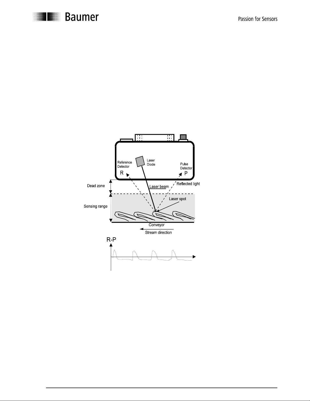
3 BASIC FUNCTION
The DENEX MICRO is a non-contact sensor which counts all kinds of printed products on
an overlapped stream. It senses the leading edge and generates one output pulse for
every product. Product thickness from a single folded sheet up to a maximum stream
thickness of 70 mm can be sensed without adjustments.
The laser diode that is used produces a visible and very intensive and focused light beam
which is projected onto the stream. The reflected light from the spot is collected by two
light sensitive detectors P and R and is analyzed by a microprocessor. The difference in
reflected light that occurs when the light spot is temporarily hidden behind the passing
product edge provides the basic data for the sensor to determine a count output pulse.
Figure 3.1 The principle of operation
The patented principle in utilizing two detectors - one for detecting the obstructed light and
the other for reference, enables the following unique benefits:
Wide operating range
High precision
Insensitive to color of paper or print
Insensitive to product thickness
Insensitive to variations in distance to copy stream
The use of a microprocessor further enhances the flexibility and reliability of the unit.
Through the use of the microprocessor, the DENEX MICRO can be adapted to different
operating modes by changing DIP-switch settings which can be reached from outside, via
the glass window.
User Manual DENEX MICRO 5/24 Baumer Electric AG
Version 2013-02, V1.6 www.baumer.com Frauenfeld, Switzerland
Page 6
4 INSTALLATION
In order to assure the best possible operating conditions as well as personal safety, it is
essential that the following instructions are followed exactly.
4.1 General Precautions
The DENEX MICRO should be installed in an environment where:
1. The equipment ambient temperature does not exceed 40º C.
2. The equipment atmosphere is free from highly flammable or combustible vapors,
corrosive chemical flumes, oil vapor, steam, excessive moisture and particles.
Avoid mounting the unit in places with strong vibrations since they can produce miscounts,
especially when thin products are counted. Make sure that the mounting bracket and
means used are rigid to withstand vibrations.
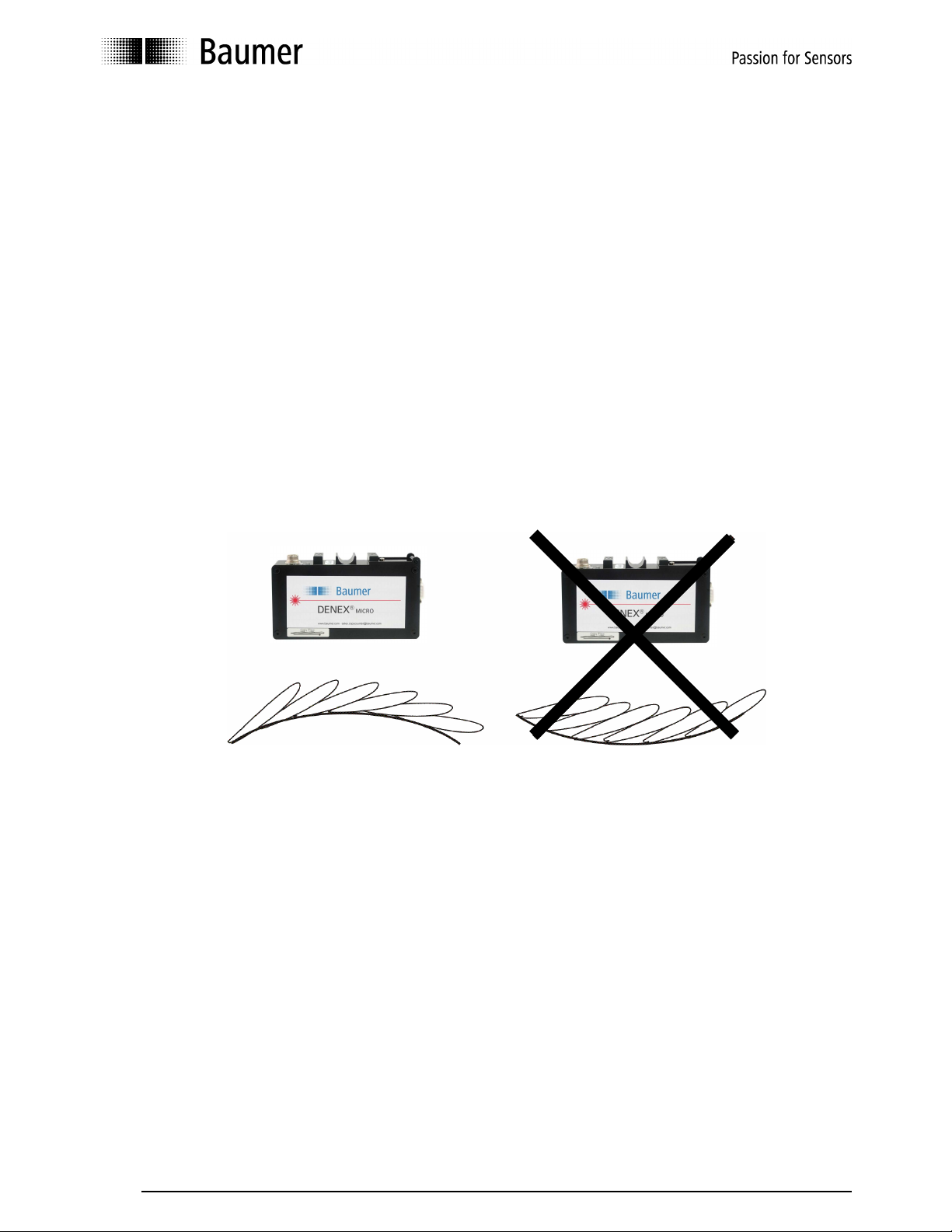
The sensor should normally be mounted on a flat conveyor. It is possible to mount the
sensor on a bent part of the conveyor according to figures below. Do not mount according
to Figure 4.1.1 (right) since it will deteriorate the function of the unit.
YES NO
Figure 4.1.1 Mounting on a non-flat conveyor.
4.2 Mechanical Installation
The sensor should be mounted parallel to, and at a distance of 100 mm from the conveyor.
The sensor will then count folded sheets up to a maximum stream thickness of 70 mm. If
the sensor is to used as a gripper sensor, refer to Appendix 1 ”Mounting and using the
sensor on a gripper conveyor”. Contact Baumer if other mountings are considered. It is
most important that the sensor is mounted the right way. It can only count in one direction.
The connector side of the sensor should be the first to meet the copies.
The laser beam must not hit any moving part of the conveyor. The path of the laser must
end with a beam stopper. See chapters 4.3 and 4.4 for more information about the type of
beam stopper used. The laser beam must never be accessible to the user!
Make sure that the mounting bracket used is rigid and that the alignment of the unit cannot
be accidentally changed. There are brackets available from Baumer.
User Manual DENEX MICRO 6/24 Baumer Electric AG
Version 2013-02, V1.6 www.baumer.com Frauenfeld, Switzerland
Page 7
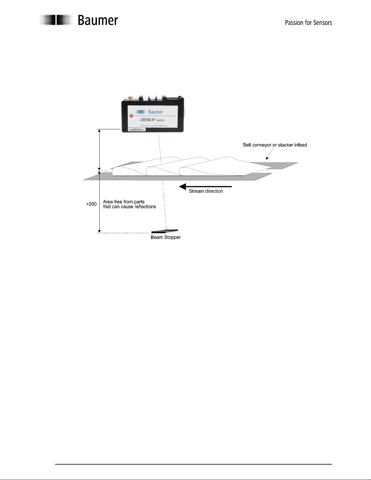
4.3 Standard Mounting with Beam Stopper
The laser does not hit anything except the beam stopper when no copies are present.
Normal back-edges will not be counted with this mounting. The beam stopper is a black
plate or dark surface no closer than 300 mm to the bottom of the sensor. See figure 4.3.1.
100
Figure 4.3.1 Standard mounting with beam stopper.
User Manual DENEX MICRO 7/24 Baumer Electric AG
Version 2013-02, V1.6 www.baumer.com Frauenfeld, Switzerland
Page 8
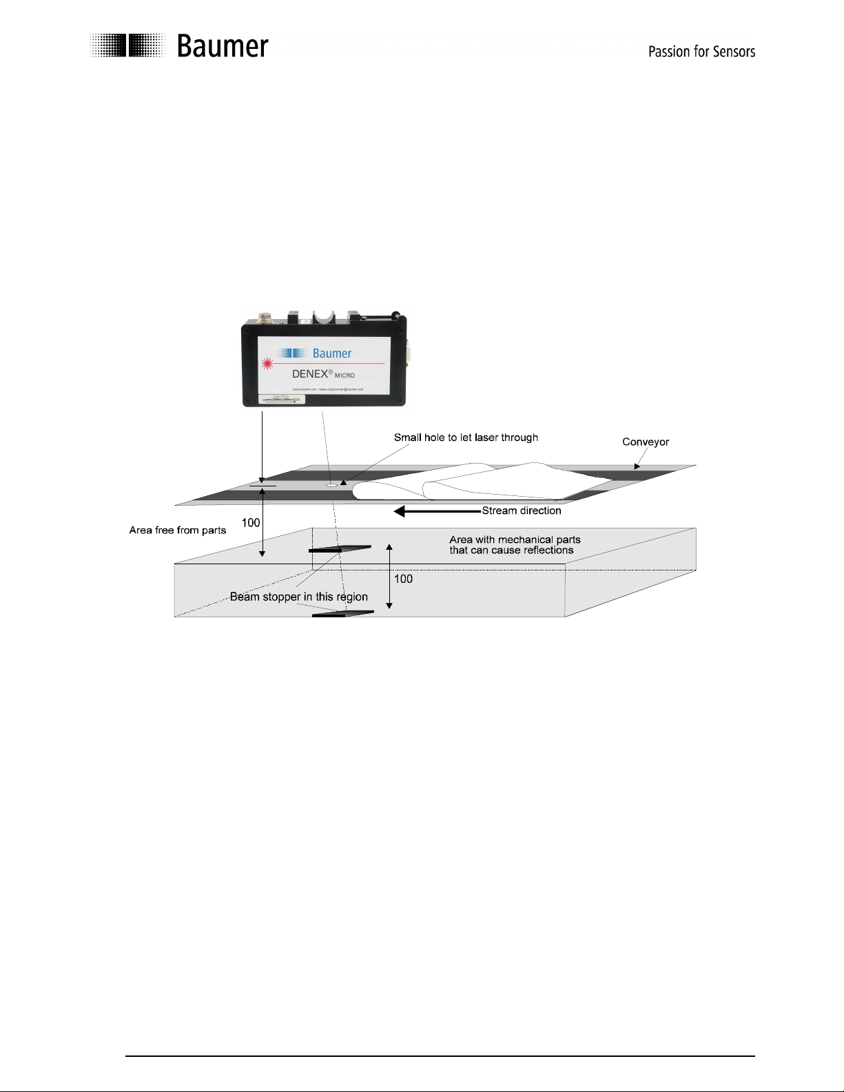
4.4 Mounting with a hole for the laser
If there are mechanical parts 200-300 mm under the sensor that can cause reflections to
the detectors, the following mounting is recommended. It requires a small hole on the
conveyor, or a plate with a hole to screen off the reflection from the parts. The beam must
still be stopped with a dark plate or other material if there is any risk for a person to look
into the laser. Make sure that the laser goes through the hole properly. Normal back-edges
are not counted with this mounting.
100
Figure 4.4.1 Mounting with a hole to let the laser through.
User Manual DENEX MICRO 8/24 Baumer Electric AG
Version 2013-02, V1.6 www.baumer.com Frauenfeld, Switzerland
Page 9

4.5 Mounting With Reference Surface
In some cases, the reflections from parts under the conveyor cannot be screened off. In
this case, the following is recommended. Let the laser hit a light, matte surface, reference
surface, like a white piece of paper or a light painted plate, at 100 mm below the sensor.
The reference surface must be smooth. If the surface is wrinkled or coarse, vibrations can
cause error pulses. Also, make sure that dust and paper pieces do not stay on the surface,
since they might create extra pulses. No extra beam stopper is needed.
The accuracy can be equally good if: no up-bent back edges are present, stream is regular
with few gaps.
Up-bended back edges can produce output pulses. This mounting is only recommended in
applications with few gaps in the stream.
100
Figure 4.5.1 Mounting with reference surface
.
User Manual DENEX MICRO 9/24 Baumer Electric AG
Version 2013-02, V1.6 www.baumer.com Frauenfeld, Switzerland
Page 10

5 Electrical installation
The interface to the copy sensor is a 7-pin connector with the following pin-out:
Matching connector: Amphenol Tuchel T3476 001, delivered with the sensor.
Pin 1 : +24VDC power
Pin 2 : + Output (collector)
Pin 3 : + Speed Sensor Input
Pin 4 : - Speed Sensor Input
Pin 5 : - Output (emitter)
Pin 6 : 0V
Pin 7 : No function (connected to pin 6 internally)
5.1 Power Connection
Proper wiring techniques are essential for successful system installation. To reduce the
effects of electrical noise interference and static discharge, the procedures outlined in this
section must be strictly followed.
The sensor shall be connected to 19 - 30V DC regulated power.
It must be free from transients!
Never connect or disconnect any cables when the power is on!
The normal current consumption is around 200mA
5.2 Output Signal
The output is a normally open, opto-isolated transistor. Every output pulse is signaled as a
closing of the output for a certain time; see also “DIP-Switch Settings” in chapter 5.
The spec for the output opto coupler is as follows:
Max load current: 150mA, Max voltage: 35V DC
5.2.1 Output Signal - Connections
The output can be used for both "current source" and "current sink" depending on what is
required for the following equipment. In current source mode, the sensor output will give a
positive pulse to the stacker/totalizer when active. In current sink mode, the sensor output
will give a negative pulse. Figures 5.2.1.1 and 5.2.1.2 shows a common 24V as power
supply and as the supply for the pulse. It is of course possible to have different power
supplies. In that case, the 24V-power is connected to pins 1 and 6, and the totalizer is
connected to pins 2 and 5.
Figure 5.2.1.1 Electrical connection, common 24V-supply. Current source (PNP).
User Manual DENEX MICRO 10/24 Baumer Electric AG
Version 2013-02, V1.6 www.baumer.com Frauenfeld, Switzerland
Page 11

Figure 5.2.1.2 Electrical connection, common 24V-supply. Current sink (NPN).
Copy Sensor
Figure 5.2.1.3 Electrical connection, separate supply for power and pulse.
5.2.2 Speed Sensor Input
There is a possibility to connect an input signal from a speed sensor, such as an encoder,
in order to give information of conveyor speed. The input can be used to obtain a fixed
blocking distance. In Mode 7 (see chapter 6, “SOFTWARE FUNCTIONS”) the input signal
is used as a control signal, if high, the blocking time is long, if low, the blocking time is
short. Normally, the dynamic blocking is used with equally good results. There are three
different modes of blocking, see chapter 6, ”SOFTWARE FUNCTIONS”.
The input is opto-isolated so that there is a separation between the sensor’s and the pulse
generator’s grounds.
The input should be min. 4.5V and max. 28V.
The maximum allowed frequency is 2.5 kHz.
Figure 5.2.2.1 Input stage for speed sensor input.
User Manual DENEX MICRO 11/24 Baumer Electric AG
Version 2013-02, V1.6 www.baumer.com Frauenfeld, Switzerland
Page 12

6 SOFTWARE FUNCTIONS
The real power with a microprocessor-based sensor is that the sensor learns what the
products and the stream look like and make decisions according to this. Before actual
settings are discussed, first a short description of the major functions and terms.
6.1 Application Setting
The sensor can be optimized around certain applications. Things like output pulse width,
Blocking Function and Back Edge Check parameters are set a little different for each
application in order to reach the highest possible accuracy.
There are four DIP-switches that tell the sensor which application it should be set for.
It is very important to set the right application!
6.2 Blocking Function
This function will eliminate false counts due to double edges or a cut-edge-first delivery.
The sensor will count edges coming within the blocking zone as one product. In
productions using stitches, extra pulses due to the stitch are blocked out by this function.
The blocking zone is a dynamic value that constantly adapts to the average distance
between copies. It will be either 15% or 30 % of the mean lap, depending on application.
The average distance between copies is 100%, see figure 6.2.1.
Figure 6.2.1 The principle of the blocking function.
The blocking zone is marked with gray. 15% is the first half, and 30% is whole area.
6.3 Back-Edge Check (In counting mode)
Normal flat back-edges are never counted. However, if the back-edge is bent, this part of
the paper can result in a miscount. The sensor can be configured to wait a certain time to
decide whether the edge that was found was really a copy or if it was an up bent backedge of the product, or a pin hole on the back of the paper. DIP-switches must be set to
choose Newspaper-application in order to activate this function.
The Back-Edge Check will affect the timing of the output pulse also on normal edges, but
will give a higher counting accuracy. Therefore, in timing applications like edge detecting,
the Back-Edge Check is disabled.
User Manual DENEX MICRO 12/24 Baumer Electric AG
Version 2013-02, V1.6 www.baumer.com Frauenfeld, Switzerland
Page 13

56 7 8
6.4 DIP-Switch Settings
An 8-pole DIP-switch can be reached via the lid on top of the sensor. Unscrewing the
screw opens the lid.
The software functions can be controlled via the DIP switches.
DIP-Switch positions
= OFF
= ON
DIP-switches 1-4 are reserved for factory
DIP-switches 5-8 are for selecting operation mode
All in OFF-position is the default setting.
DIP-Switches
Mode 0 =
Default
Mode 1
Mode 2
Mode 3
Mode 4
Mode 5
Counting mode: 15% Blocking, short Back-Edge Check, Output 5ms
Thick newspapers: 30% Blocking time, long Back-Edge Check. Output 5 ms
Counting mode: speed pulses, Blocking pulses 5, Back-edge 16, Output: 5ms
Counting mode: speed pulses, Blocking pulses 5, Back-edge 5,Output: 20ms
Thick newspapers, Blocking pulses 20. Back-edge 16, Output: 5ms
Edge detecting: fixed trig, Blocking 15%,No back-edge check, Output: 5ms
Mode 6
Mode 7
Mode 8
Mode 9
Mode 10
Mode 11
Gripper Pulse mode: For gripper conveyors, Blocking 15%, Output 20 ms
Cut edge first mode: Blocking 30 %, Back-edge 15%, Output 5 ms
Counting mode: Speed pulses, Blocking 10, Back-edge 16, Output 5ms
Commercial: Fixed trig, No Blocking, No Back-edge, Output 20 ms
Counting mode: 15% Blocking, short Back-Edge Check, Output 20ms
Counting mode: speed pulses, Blocking pulses 5, Back-edge 16, Output: 5ms
Laser power save mode is activated in all Counting/newspaper modes.
This means the laser power will be reduced after a 60 seconds gap.
User Manual DENEX MICRO 13/24 Baumer Electric AG
Version 2013-02, V1.6 www.baumer.com Frauenfeld, Switzerland
Page 14

7 LED INDICATORS
As a help for checking the operation of the sensor, there are four LED’s that are placed
close to the connector.
Figure 7.1 Position of LED:s.
7.1 The POWER-LED
The green POWER-LED indicates that the sensor has power and should be operating.
Never mount or adjust the sensor when this LED is on!
7.2 The LASER OFF-LED
The LASER OFF-LED is an indication that the laser is off. The laser will be shut off for the
following reasons:
The laser power has exceeded the allowed limits (electronic problem inside sensor)
The laser power has reached lower than acceptable level (laser is worn out, or
electronic problem)
If the laser levels are outside of the allowed limits, the sensor must be sent for repair.
The OUTPUT-LED is active when the output stage is active (set). The LED will flash for
every output pulse that is sent. The output pulse width can be set with the DIP-switches,
see chapter 5.4, ”DIP-Switch Settings”. By watching this LED, it is fairly easy to see that
the sensor is giving the correct amount of pulses.
User Manual DENEX MICRO 14/24 Baumer Electric AG
Version 2013-02, V1.6 www.baumer.com Frauenfeld, Switzerland
Page 15

Maximum Count Rate
8 TECHNICAL SPECIFICATIONS
< 600.000 copies/hour
Maximum Product Speed
1 m/s (200 ft/min) for thinnest product, up to 2 m/s otherwise
Maximum Stream Thickness
70 mm (2.76”) standard range
Minimum Product Thickness
0,25 mm (0.01”) standard range,
Distance From Conveyor
100 mm (3.94”) standard range,
Minimum Spacing Between Copies
1-5 mm (0.039-0.20”) dep. on thickness, speed and pulse width
Stream Conditions
All conditions
Operating System
RISC microprocessor
Pulse Width
5 ms (preset) or 20 ms
Output Signal
Opto-isolated 5 to 30 V max. 150 mA
Speed Sensor Input
4.5 - 28 VDC, 3 mA, max. 2.5 kHz
Matching Connector
Amphenol-Tuchel C91A T 3476 001
Laser System
Visible, switched laser diode, 650 nm, with laser safety monitor
Laser Safety Class
Class II
Estimated Lifetime of Laser
> 30,000 h @ 20ºC
Weight
800 g, 1.75 lbs.
Size
175 x 96 x 31mm, 6.89 x 3.78 x 1.22”
Power
24 V DC. 150 mA typical
Temp. Range
+10 to 40ºC, 50 to 104ºF
DENEX MICRO is a Class II Laser Product.
User Manual DENEX MICRO 15/24 Baumer Electric AG
Version 2013-02, V1.6 www.baumer.com Frauenfeld, Switzerland
Page 16

9 LASER SAFETY
The concentrated beam of optical radiation from the laser diode is potentially dangerous.
In considering the safety aspects of the use of such devices, it is the thermal effects of
absorption of this energy, which are important. However, in comparison with higher power
laser using different generating media, laser diodes are relatively safe.
A Class II-laser product as the DENEX MICRO is said to be safe if a person does not stare
into the beam. If a person accidentally would look into the laser, the strong light would
cause the eyes to shut automatically before any damage to the eyes could occur. If the
following precautions are followed, nothing can happen.
CAUTION
• Do not stare into the laser beam or a reflection of the beam from a mirror-like
surface!
• Do not move or adjust the DENEX MICRO, without first turning off the power!
The green LED must be off!
• Service on the sensor should be made by qualified personnel only!
•
The sensor must be installed in such way, that the laser does not hit a glossy,
mirror-like surface!
CAUTION
Use of controls or adjustments other than those specified herein may result in hazardous
radiation exposure.
Do not stare into beam!
User Manual DENEX MICRO 16/24 Baumer Electric AG
Version 2013-02, V1.6 www.baumer.com Frauenfeld, Switzerland
Page 17

10 SAFETY
10.1 Safety Features
The following chapter describes the safety features of the DENEX MICRO. Make regular
checks to verify the function of these features.
10.1.1 Power Control
To power off the sensor, unplug the power connection.
10.1.2 Visible Warning-LED
The green LED is the POWER-LED, which indicates that the laser is on!
Never move or adjust the sensor when the green LED is on!
11 MAINTENANCE AND REPAIRS
Before any adjustments or maintenance is carried out on the DENEX MICRO, make sure
to follow the instructions below:
Switch off the power by removing the power plug.
11.1 Maintenance at Regular Intervals
The only maintenance on the sensor which is allowed by non-DENEX Sensor authorized
personnel is cleaning the glass window, but only after first turning the sensor off.
- Clean the glass aperture with alcohol
- Remove any loose pieces of paper that can produce false counts
- Check that the beam stopper is in place and that it is not covered with dust
CAUTION
Use of controls or adjustments other than those specified
herein may result in hazardous radiation exposure.
Diode laser power up to 1 mW at 670 nm can be accessible in the interior.
Avoid exposure to beam!
User Manual DENEX MICRO 17/24 Baumer Electric AG
Version 2013-02, V1.6 www.baumer.com Frauenfeld, Switzerland
Page 18

12 RETURNING EQUIPMENT
If it is necessary to return a DENEX MICRO for repair, the following procedure should be
followed.
1. Tag the unit with the following:
• Company and contact person returning the item
• Phone, fax or email to the contact person for additional information
• Helpful information regarding the malfunction. A good description reduces
trouble shooting cost.
If the unit has been disassembled, reassemble it, making certain that all hardware is in
place. Missing parts will be charged at spare part prices.
2. Carefully pack the unit and apply appropriate cautionary stickers.
3. Advice way of returning the unit: Post (DPD), UPS, DHL or other.
4. Return unit to your dealer or directly to Baumer (see address on back page).
13 WARRANTY
Baumer Electric AG gives a warranty to the customer for quality and suitability of its
products within the scope of its technical specifications. A warranty is only given according
to prior agreement for parts which are used as safety parts within the meaning of the EU
Machinery Directive. The guarantee of Baumer Electric AG is limited to replacement or
repair of defective parts and causes which occurred before the passing of risk. Liability for
further direct and indirect losses are excluded to the extent permissible at law, more
particularly, no compensation shall be owed for any incidental loss, loss of production etc.
The guarantee lapses in any event if the customer does not use original Baumer Electric
AG replacement parts. The guarantee is not valid in any instance where the goods have
been tampered with. The customer is under a duty to examine the consignment for
completeness and transport damage immediately on receipt. Any complaints in connection
with the product shall be made in writing without delay, and evidence of such incidence
must be produced. Complaints may be made about product defects during the complete
period of guarantee at any time before and/or after processing and/or re-sale, but they are
to be notified in writing enclosing the defective part without delay after emergence. The
customer may only invoke these guarantee conditions if he proves that the defects
emerged despite proper assembly and use. The guaranty period is 24 months from
dispatch from Baumer Electric AG. The period of guarantee for replacement parts or
repairs delivered under guarantee ends with the period for the products originally supplied.
Baumer Electric AG reserves the right to charge the processing costs for sales returns and
performance tests without claim to guarantee.
User Manual DENEX MICRO 18/24 Baumer Electric AG
Version 2013-02, V1.6 www.baumer.com Frauenfeld, Switzerland
Page 19

14 TROUBLESHOOTING
The green LED (POWER) is not lit
• The sensor does not receive +24V on pin 1 and 0V on pin 6 on the Tuchel connector,
see chapter 5, ”Electrical Installation”.
• If the sensor has been working and is suddenly dead, there could be transients
knocking out the sensor. Make sure that the voltage is between 20V and 30V and is
regulated.
The red LED (LASER-OFF) is lit constantly, and no laser is present
• Re-power the sensor. Check that the laser is lit. Is the laser turned off after a while,
the laser level has changed and the sensor must be sent for repair.
The orange LED (OUTPUT-signal) is never lit, or is lit once and then no more
• Is the input signal connected? Are the DIP-switches set the way they should? As
soon as one pulse is received, the sensor believes that input pulses are used, and it starts
to wait for more. Disconnect the input signal wires if not used. Re-power the sensor and try
again.
The orange LED (OUTPUT-signal) is lit for every copy, but no pulse, or a different number of
pulses, is received to the following equipment
• The interfacing is bad. Check again that the sensor is connected the way it should,
see chapter 5 ”Electrical Installation”.
• Is the sensor supposed to source or sink the signal? Should the pulse be positive or
negative? See chapter 5.2
• Is the totalizer (pulse counter) used, a battery powered device? It can be a problem
because of the voltage drop over the output transistor in the sensor. There is approx. 0.8V
voltage drop over emitter and collector at 2 mA which could mean that the totalizer does
not see any changes in state, i.e. from ”high” to ”low”. Check with a scope between pulse
and ground.
• The opto-coupler in the sensor can be faulty. See the specs of the opto-coupler.
First copy edge is not counted or back-edges are counted (does not apply for a mounting
with reference)
• Check that the laser does not hit anything within 300 mm below the sensor when no
products are present.
• If the laser hits a plate within 300 mm below the sensor, check the possibility of
making a hole in the plate. Drill a hole with a diameter of 5 mm, which the laser can pass
through. The laser must still be stopped by a black plate, because of safety regulations!
• If back-edges are counted, check the distance from the up-bent back-edge to the end
of the paper.
User Manual DENEX MICRO 19/24 Baumer Electric AG
Version 2013-02, V1.6 www.baumer.com Frauenfeld, Switzerland
Page 20

The sensor does not read the Speed Sensor Input Signal
• Check polarity and levels according to chapter 5.2.2, ”Speed Sensor Input”. Is the
speed very high? It should be max. 2.5 kHz.
There is an overcount (too few copies in the bundle)
• Check the mechanical installation. The sensor must be parallel to the stream.
• For cut-edge first delivery, or with copies with stitches or other non-folded edges, try
changing the application so that the Blocking Zone is greater, see chapter 6, ”SOFTWARE
FUNCTIONS”.
• Back-edges could be counted. Check by running one paper at a time, and see if
there is an extra pulse sent at the end of the paper.
• If the surface of the product is wavy, try tilting the sensor 5 - 10° according to figure
below.
Some products are not counted (too many copies in the bundles)
• Check the mechanical installation. The sensor must be parallel to the stream.
• Check the interface. See previous page.
• If the product stream is very irregular, it could be that the sensor is blocking out
products coming too close. Try choosing an application with a shorter blocking, see
chapter 6, ”SOFTWARE FUNCTIONS”.
• Make sure that the stacker has not got an internal Blocking Zone which is set in a
way that it blocks out pulses from the sensor.
• If the product with the problem is very black and very thin, try lowering the sensor 10-
20 mm closer to the product stream.
• Are the products very tilted when they pass the sensor? The max angle allowed is
15° for a 0.25 mm product.
•
Still Problem?
Give your Baumer DENEX dealer a call.
User Manual DENEX MICRO 20/24 Baumer Electric AG
Version 2013-02, V1.6 www.baumer.com Frauenfeld, Switzerland
Page 21

ACCESSORIES AVAILABLE FROM Baumer
There is a number of accessories available that can save you time and ensure a good
operation of the sensor:
Brackets
Baumer has standard brackets for mounting the DENEX sensors above the conveyor and
for many different brands Installation of a Totalizer beside the conveyor. Special brackets
for gripper conveyors are also available.
User Manual DENEX MICRO 21/24 Baumer Electric AG
Version 2013-02, V1.6 www.baumer.com Frauenfeld, Switzerland
Page 22

15 APPENDIX
1. Size Diagram with Laser Beam Projection
RW 980130
919-06a.CDR
RW
LCS 919-06A
M8
DENEX Systems Technology AB
DENEX
DENEX CopySensor
DENEX
OUTLINE DRAWING
55 65
A-A
15,5
3/4" Shaft or 19 mm shaft
Suitable bracket available
from DENEX
Part no. 53C6014
120
100
70
175
19
92,7
98,8
103,2
101,4
12
A A
31
96
User Manual DENEX MICRO 22/24 Baumer Electric AG
Version 2013-02, V1.6 www.baumer.com Frauenfeld, Switzerland
Page 23

16 Supplements
User Manual DENEX MICRO 23/24 Baumer Electric AG
Version 2013-02, V1.6 www.baumer.com Frauenfeld, Switzerland
Page 24

Baumer Electric AG
Sensor Solutions
Hummelstrasse 17
CH - 8500 Frauenfeld
Phone +41 (0) 527281122
Fax +41 (0) 527281110
sales.copycounter@baumer.com
www.baumer.com
Technical data subject to change Printed in Switzerland No. 11084089
User Manual DENEX MICRO 24/24 Baumer Electric AG
Version 2013-02, V1.6 www.baumer.com Frauenfeld, Switzerland
 Loading...