

Page 1
USER MANUAL
FOR DENEX VERSIONS: 2009
®
DENEX
Gripper LED
FLDM 180C1101/S42
Page 2

READ THIS FIRST
Before installing, operating, opening, or applying the DENEX Gripper LED, read and
understand the contents of this manual.
Always observe the following warnings and cautions when operating or working on the
equipment.
CAUTION
Use of controls or adjustments or performance procedures other
than those specified herein may result in hazardous radiation exposure.
Do not stare into LED aperture.
Always turn off the sensor before moving or adjusting it.
The DENEX Gripper LED must be applied, installed, adjusted, and maintained only by
qualified personnel who are familiar with the operation of the DENEX Gripper LED and its
associated components.
User Manual DENEX Gripper LED 2/24 Baumer Electric AG
Version 2013-02, V1.4 www.baumer.com Frauenfeld, Switzerland
Page 3

CONTENTS
1 INTRODUCTION _____________________________________________________ 4
2 RECEIVING AND HANDLING _________________________________________ 4
3 BASIC FUNCTION ___________________________________________________ 4
4 INSTALLATION ______________________________________________________ 5
4.1 General Precautions ____________________________________________________ 5
4.2 Mechanical Installation _________________________________________________ 5
5 ELECTRICAL INSTALLATION ________________________________________ 7
5.1 Power Connection _____________________________________________________ 7
5.2 Output Signal __________________________________________________________ 7
5.2.1 Output Signal - Connections ______________________________________ 8
5.2.2 Speed Sensor Input ______________________________________________ 9
6 SOFTWARE FUNCTIONS ____________________________________________ 10
6.1 Mode Setting _________________________________________________________ 10
6.2 Blocking Function _____________________________________________________ 10
6.3 Gripper Pulse Mode ___________________________________________________ 11
6.4 DIP-Switch Settings ___________________________________________________ 13
7 LED INDICATORS __________________________________________________ 14
7.1 The POWER-LED ______________________________________________________ 14
7.2 The ”LED OFF”- LED __________________________________________________ 14
7.3 The OUTPUT- LED ____________________________________________________ 14
7.4 The STATUS- LED _____________________________________________________ 14
8 TECHNICAL SPECIFICATIONS ______________________________________ 15
9 ACCESSORIES AVAILABLE FROM DENEX ___________________________ 16
9.1 Conversion kits _______________________________________________________ 16
9.1.1 Exchanging Ferag-Finger with Baumer proximity switch _____________ 16
10 MAINTENANCE AND REPAIRS _____________________________________ 17
10.1 Maintenance at Regular Intervals _____________________________________ 17
11 RETURNING EQUIPMENT _________________________________________ 17
12 WARRANTY ______________________________________________________ 18
13 TROUBLESHOOTING _____________________________________________ 19
14 APPENDIX _______________________________________________________ 21
15 Supplements _____________________________________________________ 23
User Manual DENEX Gripper LED 3/24 Baumer Electric AG
Version 2013-02, V1.4 www.baumer.com Frauenfeld, Switzerland
Page 4

1 INTRODUCTION
WARNING
When a DENEX Gripper LED is combined with user
selected components to form a system, the user is responsible for proper selection of parts
and subsequent operation. This unit shall be installed, adjusted and serviced only by
qualified personnel who are familiar with the operation of the
DENEX Gripper LED and other system components. Serious personal injury and
equipment damage may result if this procedure is not followed.
2 RECEIVING AND HANDLING
Upon delivery of the equipment, thoroughly inspect the shipping containers and contents
for indications of damage incurred in transit. If any concealed loss or damage is
discovered later, notify the freight or express agent.
3 BASIC FUNCTION
The DENEX Gripper LED is a non-contact sensor which counts all kinds of products
carried in a Gripper. It senses the leading edge and generates one output pulse for every
product. Product thickness from a single folded sheet and up can be sensed without
adjustments.
The Infra Red-Light Emitting Diode (IR-LED) that is used produces a light beam which is
projected onto the stream. The reflected light from the spot is collected by two light
sensitive detectors P and R and is analyzed by a microprocessor. The difference in
reflected light that occurs when the light spot is temporarily hidden behind the passing
product edge provides the basic data for the sensor to determine a count.
The patented principle in utilizing two detectors - one for detecting the obstructed light and
the other for reference, enables the following unique benefits:
• Wide operating range
• High accuracy
• Insensitive to color of paper or print
• Insensitive to product thickness
The use of a microprocessor further enhances the flexibility and reliability of the unit.
Through the use of the microprocessor, the DENEX Gripper LED can be adapted to
different operating modes by changing DIP-switch settings which can be reached from
outside, via the lid on top of the unit.
User Manual DENEX Gripper LED 4/24 Baumer Electric AG
Version 2013-02, V1.4 www.baumer.com Frauenfeld, Switzerland
Page 5

4 INSTALLATION
In order to assure the best possible operating conditions, it is essential that the following
instructions are followed exactly.
4.1 General Precautions
The DENEX Gripper LED should be installed in an environment where:
1. The equipment ambient temperature does not exceed 40º C.
2. The equipment atmosphere is free from highly flammable or combustible vapors,
corrosive chemical flumes, oil vapor, steam, excessive moisture and particles.
Avoid mounting the unit in places with strong vibrations since they can produce miscounts,
especially when thin products are counted. Make sure that the mounting bracket is rigid to
withstand vibrations.
4.2 Mechanical Installation
The sensor should be installed parallel to the conveyor and at a distance of 40 mm from
the copy edge, see figure 4.2.1. It is most important that the sensor is mounted the right
way. It can only count in one direction. ”The connector side of the sensor should meet the
edge first”.
As a “Target”, mount a white surface at 120 to 150 mm below the sensor, and parallel to
the bottom of the sensor. Check that the LED 4 indicates Target Status OK, see chapter 6,
”SOFTWARE FUNCTIONS”. Failure to comply will make the counter less accurate.
Mount the DENEX Gripper LED as close as possible to the Grippers without risking being
in contact with the Grippers. A 5 mm safety distance is recommended.
There must be at least 5 mm of air between the edge that the sensor should detect, and
the previous product.
If the sensor is to be used together with a Gripper pulse, it must be possible to move the
sensor sideways for the length of one Gripper, see figure 4.2.2. See further chapter 6.3,
”Gripper Pulse Mode”.
User Manual DENEX Gripper LED 5/24 Baumer Electric AG
Version 2013-02, V1.4 www.baumer.com Frauenfeld, Switzerland
Page 6
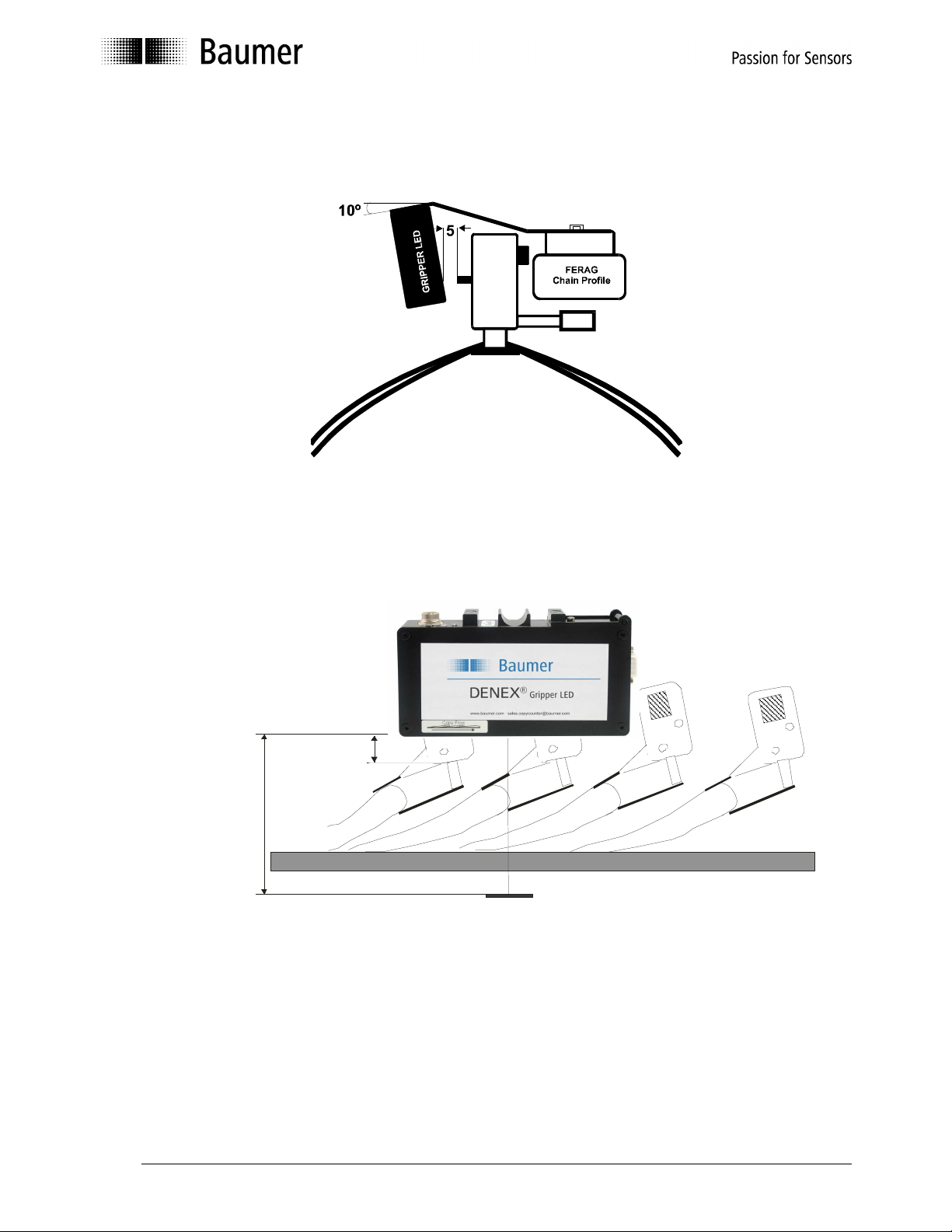
Figure 4.2.1 Installing the sensor on a Ferag TTR Gripper conveyor.
120-150 mm
Figure 4.2.2 Installing the sensor on a Ferag TTR Gripper conveyor.
Min 30 mm
Rec 50-60 mm
DENEX
DENEX
Target plate
Laser CopySensor™
GRIPPER LED
Support bars
User Manual DENEX Gripper LED 6/24 Baumer Electric AG
Version 2013-02, V1.4 www.baumer.com Frauenfeld, Switzerland
Page 7

5 ELECTRICAL INSTALLATION
The copy sensor has a 7-pin male connector with the following pin-out:
Matching female connector is Amphenol Tuchel T3476 001, delivered with the sensor.
Pin 1 : +24Vin
Pin 2 : + Output (Collector)
Pin 3 : + Speed Sensor Input
Pin 4 : - Speed Sensor Input
Pin 5 : - Output (Emitter)
Pin 6 : 0V
Pin 7 : No function (connected to pin 6 internally)
5.1 Power Connection
Proper wiring techniques are essential for successful system installation. To reduce the
effects of electrical noise interference and static discharge, the procedures outlined in this
section must be strictly followed.
The sensor shall be connected to 19 - 30V DC regulated power.
It must be free from transients!
Never connect or disconnect any cables when the power is on!
The normal current consumption is around 200mA.
5.2 Output Signal
The output is a normally open, opto-isolated transistor. Every output pulse is signaled as a
closing of the output; see “DIP-Switch Settings” in chapter 6.4.
The specification for the output opto-coupler is as follows:
Max load current: 150mA
Max voltage: 35V DC
User Manual DENEX Gripper LED 7/24 Baumer Electric AG
Version 2013-02, V1.4 www.baumer.com Frauenfeld, Switzerland
Page 8
Copy
Sensor
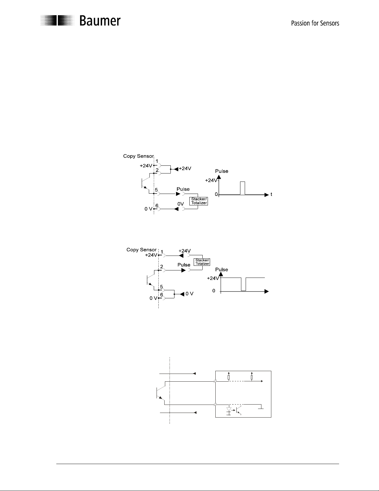
5.2.1 Output Signal - Connections
The output can be used for both "current source" and "current sink" depending on what is
required for the connected equipment. It can be normally open or normally closed, see
chapter 6, ”SOFTWARE FUNCTIONS”.
In current source mode, the sensor output will give a positive output pulse when active.
In current sink mode, the sensor output will give a negative pulse.
Figures 5.2.1.1 and 5.2.1.2 show a common 24 VDC as power supply and as the supply
for the pulse. It is possible to have different power supplies. In that case, the 24V-power is
connected to pins 1 and 6, and the output is connected to pins 2 and 5, see figure 5.2.1.3.
Figure 5.2.1.1 Electrical connection, common 24VDC-supply. Current source (PNP).
Figure 5.2.1.2 Electrical connection, common 24VDC-supply. Current sink (NPN).
DENEX CopySensor™ Control system/Stacker/Totalizer
+24V
Examples of input stage
TTL
or
0V
Figure 5.2.1.3 Electrical connection, separate supply for power and pulse.
User Manual DENEX Gripper LED 8/24 Baumer Electric AG
Version 2013-02, V1.4 www.baumer.com Frauenfeld, Switzerland
Page 9

Connector
5.2.2 Speed Sensor Input
There is a possibility to connect an input signal from a speed sensor, such as an encoder
giving for example 100 pulses per Gripper, or a proximity switch that senses the Grippers,
in order to give information conveyor speed and Gripper position to the DENEX Gripper
LED. This information can help the sensor to increase accuracy, especially for productions
with two papers per Gripper.
The speed sensor input of the DENEX Gripper LED is opto-isolated, i.e. there is a
separation between the DENEX Gripper LED’s and the Speed Sensor’s grounds.
The input should be min. 4.5V and max. 28V.
The maximum allowed frequency is 2.5 kHz.
Input signal
3
4
Figure 5.2.2.1 Input stage for speed sensor input.
There is a variety of types of proximity switches available: NPN, PNP, normally open, and
normally closed. However, the principle is the same; when a Gripper is close to the switch,
it will change status on the output.
The DENEX Gripper LED will sense this change and use it in the Blocking Function routine.
See chapter 6, ”SOFTWARE FUNCTIONS”.
User Manual DENEX Gripper LED 9/24 Baumer Electric AG
Version 2013-02, V1.4 www.baumer.com Frauenfeld, Switzerland
Page 10

100%
100%
100%
6 SOFTWARE FUNCTIONS
The real power with a microprocessor based sensor is that the sensor learns what the
products and the stream look like and make decisions according to this.
Before actual settings are discussed, first a short description of the major functions and
terms.
6.1 Mode Setting
The DENEX Gripper LED has a Single Production Mode and a Double Production Mode.
The difference is the Blocking Zone, see below. There are also modes for replacement of
mechanical fingers
There are four DIP-switches that tell the sensor which application it should be set for.
It is very important to set the right application!
6.2 Blocking Function
This function will eliminate false counts due to double edges or a cut-edge-first delivery.
The sensor will count edges coming within the blocking zone as one product. In
productions using stitches, extra pulses due to the stitch are blocked out by this function.
The blocking zone is a dynamic value that constantly adapts to the average distance
between copies. It will be either 15% or 30 % of the mean lap, depending on application.
The average distance between copies is 100%, see figure 6.2.1.
If speed sensor pulses are used, the blocking will switch to a fixed number of pulses
instead of a dynamic time.
15%
30%
15%
30%
15%
30%
15%
30%
Figure 6.2.1 The principle of the dynamic blocking function. Blocking Zone is marked with
grey. 15% is the first half, and 30% is whole area.
User Manual DENEX Gripper LED 10/24 Baumer Electric AG
Version 2013-02, V1.4 www.baumer.com Frauenfeld, Switzerland
Page 11

6.3 Gripper Pulse Mode
The best way of handling two copies in a Gripper, and cut-edge first delivery is to attach a
Gripper pulse to the speed sensor input. This is a signal which is normally available in
Gripper conveyors. Normally it is a proximity switch which senses each Gripper. This pulse
can be connected to the input on the DENEX Gripper LED as described in chapter 4.
With DIP-switches the Gripper Pulse Mode is selected.
In this mode, the output signal is activated when a copy edge comes, and it stays on until
the Gripper pulse/proximity switch changes status, see figure 6.3.1.
There are four alternative setting depending on desired polarity of DENEX Gripper LED
Output Pulse and Speed Sensor Input.
During the time that the output pulse is active, no extra pulses can be sent. This will
simulate a mechanical switch (Ferag-finger), since the pulse stays on for a specific
distance instead of a fixed time, but without the bouncing that mechanical sensors
produce.
By making an adjustable bracket where either the sensor or the proximity switch for the
Gripper pulse can be adjusted sideways, a Blocking Zone of any size can be chosen.
Figure 6.3.1 The relation between the Output Pulse and the Gripper Pulse.
User Manual DENEX Gripper LED 11/24 Baumer Electric AG
Version 2013-02, V1.4 www.baumer.com Frauenfeld, Switzerland
Page 12

To adjust the sensor to get a blocking of approximately 50 % do the following:
• Make a bracket that enables the sensor to be moved sideways, or order one from
Baumer. Specify type of conveyor!
• Set the sensor in Gripper Pulse Mode, see chapter 6.4
• Watch the Output LED during production. It should be flashing.
The next step can be dangerous! Watch your hands if you do the movement during
run!
• Move the sensor sideways until the Output LED is ON for approximately as long as it is
OFF to get 50 % duty cycle.
• You can also check with a scope, either on the Output directly or between TP8 and
TP1, see chapter 6.
If this is done OK, the sensor will only count one edge for half a Gripper, which will be the
ideal situation.
User Manual DENEX Gripper LED 12/24 Baumer Electric AG
Version 2013-02, V1.4 www.baumer.com Frauenfeld, Switzerland
Page 13

Mode
STATUS LED shows:
6.4 DIP-Switch Settings
An 8-pole DIP-switch can be reached via the lid on top of the sensor. Unscrewing the
screw opens the lid.
The software can be controlled via the DIP switches.
DIP-Switch positions
= OFF
= ON
DIP-switches 1-4 are reserved for factory.
DIP-switches 5-8 are for selecting operation mode
All in OFF-position is the default setting.
DIP-Switches
5 6 7 8
Mode 0 =
Default
Mode 1
Mode 2
Mode 3
Mode 4
Mode 5
Mode 6
Mode 7
Mode 8
Mode 9
Mode 10
Mode 11
Standard newspaper: 15% Blocking, Output 5ms
Double production: 30% Blocking time. Output 5 ms
Gripper Pulse Mode Output NO, Reset on falling edge of speed sensor
Gripper Pulse Mode Output NC, Reset on falling edge of speed sensor
Gripper Pulse Mode Output NO, Reset on rising edge of speed sensor
Gripper Pulse Mode Output NC, Reset on rising edge of speed sensor
Gripper Pulse Mode Output NO, Reset on falling edge of speed sensor
Standard newspaper: 15% Blocking, Output 20ms
Double production: 30% Blocking time, Output 20 ms
Standard newspaper: 30% Blocking, Output 20ms
reserved
reserved
0 Lit when target is recognized by sensor
1 Lit when target is recognized by sensor
2 Speed sensor status
3 Speed sensor status
4 Speed sensor status
5 Speed sensor status
6 Lit when target is recognized by sensor
7 Lit when target is recognized by sensor
8 Lit when target is recognized by sensor
9 Not applicable
User Manual DENEX Gripper LED 13/24 Baumer Electric AG
Version 2013-02, V1.4 www.baumer.com Frauenfeld, Switzerland
Page 14

POWER (GREEN)
7 LED INDICATORS
There are four LED’s that are placed close to the connector for checking the operation of
the sensor,
LED OFF (RED)
OUTPUT (ORANGE)
STATUS (YELLOW)
Figure 7.1 Position of LED:s.
7.1 The POWER-LED
The green POWER-LED indicates that the sensor has power and should be operating.
Never mount or adjust the sensor when this LED is on!
7.2 The ”LED OFF”- LED
The ”LED OFF”-LED is an indication that the light emitting diode is off. The LED could be
shut off for the following reasons:
• The LED-power level has changed in an uncontrolled way (electronic problem inside
sensor)
• The LED-power level is too low to ensure a good operation
If the LED-levels are outside of the allowed limits, the sensor must be sent for repair.
7.3 The OUTPUT- LED
The OUTPUT-LED is active when the output stage is active (set). The LED will flash for
every output pulse that is sent. The output pulse width can be set with the DIP-switches,
see chapter 6.4, ”DIP-Switch Settings”. By watching this LED, it is fairly easy to see that
the sensor is giving the correct amount of pulses.
7.4 The STATUS- LED
see chapter 6, ”SOFTWARE FUNCTIONS”.
User Manual DENEX Gripper LED 14/24 Baumer Electric AG
Version 2013-02, V1.4 www.baumer.com Frauenfeld, Switzerland
Page 15

8 TECHNICAL SPECIFICATIONS
Maximum Count Rate
> 300.000 copies/hour
Maximum Product Speed
5 m/s
Minimum Distance to Product
20 mm
Minimum Product Thickness
No limit as long as it is carried in a Gripper, and there is an air gap of >5mm
Distance to Back-Edge of Product
120 -150 mm
Operating System
RISC microprocessor
Pulse Width
5 ms (preset) or 20 ms
Output Signal
Opto-isolated 5 to 30 V max. 150 mA
Speed Sensor Input
4.5 - 28 VDC, 3 mA, max. 2.5 kHz
Matching Connector
Amphenol-Tuchel C91A T 3476 001
Light System
IR-LED, with ambient light suppression and power monitor
Estimated Lifetime of LED
> 100,000 h @ 20ºC
Weight
800 g, 1.75 lbs.
Size
175 x 96 x 31mm, 6.89 x 3.78 x 1.22”
Power
24 V DC. 230 mA typical
Temp. Range
+10 to 40ºC, 50 to 104ºF
User Manual DENEX Gripper LED 15/24 Baumer Electric AG
Version 2013-02, V1.4 www.baumer.com Frauenfeld, Switzerland
Page 16

9 ACCESSORIES AVAILABLE FROM DENEX
There are a number of accessories available from Baumer that can save you time and
ensure a good operation of the sensor. Kits for replacing mechanical or older sensors are
available. See web site www.baumer.com or www.denex.com for more updated
information.
9.1 Conversion kits
Order a Ferag Finger to Gripper LED Conversion Kit from Baumer to make the installation
quick and easy.
For TTR: Part. No. 11084181 (formerly 51G6040) or
For UTR: Part. No.11084159 (formerly 51G6050)
Full instruction is included in the kit containing bracket and cable.
9.1.1 Exchanging Ferag-Finger with Baumer proximity switch
Check the type (NPN or PNP) of Ferag-Finger that is used.
Check the type (NPN or PNP) of Baumer that is used.
Wire according to chapter 5.
• If the output is inactive (0V on the output) when no papers are present and the Baumer
is inactive when no Gripper is close to it Use Mode 2.
• If the output is active (LED is ON at the Finger) when no papers are present and the
Baumer is inactive when no Gripper is close to it Use Mode 3.
• If the output is inactive (0V on the output) when no papers are present and the Baumer
is active when no Gripper is close to it Use Mode 4.
• If the output is active (LED is ON at the finger) when no papers are present and the
Baumer is active when no Gripper is close to it Use Mode 5.
Wire the DENEX Gripper LED Output Cable either for current source or current sink,
depending on the Ferag input stage.
User Manual DENEX Gripper LED 16/24 Baumer Electric AG
Version 2013-02, V1.4 www.baumer.com Frauenfeld, Switzerland
Page 17

10 MAINTENANCE AND REPAIRS
Before any adjustments or maintenance is carried out on the DENEX Gripper LED, make
sure to follow the instructions below:
Switch off the power by removing the power plug. Never stare into the LED aperture
for a long time!
10.1 Maintenance at Regular Intervals
To ensure the best operation, by following the steps above:
• Clean the glass aperture with alcohol
• Remove any loose pieces of paper that can produce false counts
• Check that the target is mounted the way it should be
11 RETURNING EQUIPMENT
If it is necessary to return a DENEX Gripper LED for repair, the following procedure should
be followed.
1. Tag the unit with the following:
• Company and contact person returning the item
• Phone, fax or email to the contact person for additional information
• Helpful information regarding the malfunction. A good description reduces
trouble shooting cost.
If the unit has been disassembled, reassemble it, making certain that all hardware is in
place. Missing parts will be charged at spare part prices.
2. Carefully pack the unit and apply appropriate cautionary stickers.
3. Advice way of returning the unit: Post (DPD), UPS, DHL or other.
4. Return unit to your dealer or directly to Baumer (see address on back page).
User Manual DENEX Gripper LED 17/24 Baumer Electric AG
Version 2013-02, V1.4 www.baumer.com Frauenfeld, Switzerland
Page 18

12 WARRANTY
Baumer Electric AG gives a warranty to the customer for quality and suitability of its
products within the scope of its technical specifications. A warranty is only given according
to prior agreement for parts which are used as safety parts within the meaning of the EU
Machinery Directive. The guarantee of Baumer Electric AG is limited to replacement or
repair of defective parts and causes which occurred before the passing of risk. Liability for
further direct and indirect losses are excluded to the extent permissible at law, more
particularly, no compensation shall be owed for any incidental loss, loss of production etc.
The guarantee lapses in any event if the customer does not use original Baumer Electric
AG replacement parts. The guarantee is not valid in any instance where the goods have
been tampered with. The customer is under a duty to examine the consignment for
completeness and transport damage immediately on receipt. Any complaints in connection
with the product shall be made in writing without delay, and evidence of such incidence
must be produced. Complaints may be made about product defects during the complete
period of guarantee at any time before and/or after processing and/or re-sale, but they are
to be notified in writing enclosing the defective part without delay after emergence. The
customer may only invoke these guarantee conditions if he proves that the defects
emerged despite proper assembly and use. The guaranty period is 24 months from
dispatch from Baumer Electric AG. The period of guarantee for replacement parts or
repairs delivered under guarantee ends with the period for the products originally supplied.
Baumer Electric AG reserves the right to charge the processing costs for sales returns and
performance tests without claim to guarantee.
User Manual DENEX Gripper LED 18/24 Baumer Electric AG
Version 2013-02, V1.4 www.baumer.com Frauenfeld, Switzerland
Page 19

13 TROUBLESHOOTING
The green LED (POWER) is not lit
• The sensor does not receive +24VDC on pin 1 and 0V on pin 6 on the Tuchel
connector, see chapter 5., ”Electrical Installation”.
• If the sensor has been working and is suddenly dead, there could be transients
knocking out the sensor. Make sure that the voltage is between 20V and 30V and is
well regulated.
The red LED (LED-OFF) is lit constantly, and sensor is dead
• Repower the sensor. Check that the green POWER-LED is lit. Is the LED-OFF turned
on after awhile? If so, the LED level has changed and the sensor must be sent for
repair.
The orange LED (OUTPUT) is never lit, or is lit once and then no more
• Are the DIP-switches set the way they should? Is the input signal connected? As
soon as one pulse is received, the sensor believes that input pulses are used, and it
starts to wait for more. Disconnect the input signal wires if not used. Power up the
sensor and try again.
The orange LED (OUTPUT) is lit for every copy, but no output pulse, or a different number of
pulses, is received to the connected equipment
• The interfacing is bad. Check again that the sensor is connected the way it should,
see chapter 5., ”Electrical Installation”.
• Is the sensor supposed to source or sink the signal? Should the pulse be positive or
negative? See chapter 5.
• Is the totalizer (pulse counter) used, a battery powered device? It can be a problem
because of the voltage drop over the output transistor in the sensor. There is approx.
0.8V voltage drop over emitter and collector at 2 mA which could mean that the
totalizer does not see any changes in state, i.e. from ”high” to ”low”. Check with a
scope between pulse and ground.
First copy is not counted
• Check the position of the target. It should be 120 to 150 mm below the sensor. It
should be white or at least grey. Check that the target is parallel to the sensor.
• Use the Target Status-LED to verify the target position.
The sensor does not read the Speed Sensor Input Signal
• Check polarity and levels according to chapter 5.2.2, ”Speed Sensor Input”. Is the
speed very high? It should be max. 2.5 kHz.
User Manual DENEX Gripper LED 19/24 Baumer Electric AG
Version 2013-02, V1.4 www.baumer.com Frauenfeld, Switzerland
Page 20

There is an over count. More pulses than copies
• Check the mechanical installation. The sensor must be parallel to the support bars
and the back edge of the product.
• Back-edges could be counted if the back edge is not parallel to the sensor. Check by
running one paper at a time, and see if there is an extra pulse sent at the end of the
paper.
• If a product comes closer than 10 mm to the sensor, it can be a problem. In that
case, move the sensor higher above the stream.
• Keep some samples of the copy, with the problem and talk to your distributor.
• If there are two products in one Gripper, the best way to block out pulses is the
Gripper Pulse Mode, see chapter 6.3.
Some products are not counted
• Check the mechanical installation. The sensor can handle the thinnest products only
if the edge is approx 30-40 mm below the sensor and there is an air-gap of more
than 5 mm.
• Check the interface. See chapter 5.2.
• If in Gripper Pulse Mode, it is extremely important that the Gripper Pulse is received
for every Gripper on the chain. Check the installation of the DENEX Gripper LED and
the proximity switch. The output pulse duty cycle should be approximately 50 %.
Still Problem?
• Give your dealer a call or contact Baumer directly.
If the unit has a hardware fault, return it to your dealer for repair.
See chapter 11, ”RETURNING EQUIPMENT”. Do not forget to write a short description of
what went wrong. When did it stop to work? What type of equipment was the sensor
connected to? Any information is helpful
.
User Manual DENEX Gripper LED 20/24 Baumer Electric AG
Version 2013-02, V1.4 www.baumer.com Frauenfeld, Switzerland
Page 21

14 APPENDIX
1.
Ferag TTR Finger to DENEX Gripper LED Conversion kit
2.
Ferag UTR Finger to DENEX Gripper LED Conversion kit
A 1: Conversion kit: Ferag TTR finger to Gripper LED. Part no. 11084181
This conversion kit will provide an easy to install solution when replacing the mechanical finger in Ferag TTR
conveyors with the non-contact DENEX Gripper LED.
Replace the mechanical finger from this
To the DENEX solution:
• Compatible with standard brackets
• Simple electrical installation with pre-manufactured cables
• Easy to adjust for accurate counting
User Manual DENEX Gripper LED 21/24 Baumer Electric AG
Version 2013-02, V1.4 www.baumer.com Frauenfeld, Switzerland
Page 22

A2: Conversion kit: Ferag UTR finger to Gripper LED. Part no. 11084159
This conversion kit will provide an easy to install solution when replacing the mechanical finger in Ferag UTR
conveyors with the non-contact DENEX Gripper LED.
Replace the mechanical finger from this
To the DENEX solution:
• Compatible with standard brackets
• Simple electrical installation with pre-manufactured cables
• Easy to adjust for accurate counting
User Manual DENEX Gripper LED 22/24 Baumer Electric AG
Version 2013-02, V1.4 www.baumer.com Frauenfeld, Switzerland
Page 23

15 Supplements
User Manual DENEX Gripper LED 23/24 Baumer Electric AG
Version 2013-02, V1.4 www.baumer.com Frauenfeld, Switzerland
Page 24

Baumer Electric AG
Sensor Solutions
Hummelstrasse 17
CH - 8500 Frauenfeld
Phone +41 (0) 527281122
Fax +41 (0) 527281110
sales.copycounter@baumer.com
www.baumer.com
Technical data subject to change Printed in Switzerland No. 11084086
User Manual DENEX Gripper LED 24/24 Baumer Electric AG
Version 2013-02, V1.4 www.baumer.com Frauenfeld, Switzerland
 Loading...