

Page 1

ISL95SS 90 cm Island
cooker hood
Page 2

User Manual for your Baumatic
ISL95SS Cooker
hood
90 cm Island cooker hood in stainless
steel
NOTE: This User Instruction Manual contains important
information, including safety & installation points, which will
enable you to get the most out of your appliance. Please keep it
in a safe place so that it is easily available for future reference.
1
DD 14/04/08
Page 3

CONTENTS
YOUR COOKER HOOD’S SPECIFICATIONS ….……………..………….3
IMPORTANT SAFETY INFORMATION……………………………….…4-5
CARING FOR THE ENVIRONMENT…………………………………………6
USING YOUR COOKER HOOD………………………………..……………..7
MAINTAINING AND CLEANING YOUR COOKER HOOD ……….8-10
INSTALLATION INSTRUCTIONS ……………………….……...….11-19
CARBON FILTER …………..11
ELECTRICAL CONNECTION……………12
INSTALLING THE COOKER HOOD….….13-15
INSTALLING THE PIPE…………..16-17
INSTALLATION NOTES – EXTRACTION / PURIFYING VERSION .….18
NOTE ON INSTALLING THE VERSION WITH LOWER BRACKET..……19
TROUBLESHOOTING ……………………………………………20
CONTACT DETAILS…………………………………………………………..21
2
Page 4

Specifications of your ISL95SS Cooker Hood
Congratulations on purchasing a Baumatic Cooker
Hood!
To fully enjoy using your appliance long into the future,
please firstly familiarise yourself with its specifications,
safety advice and operational instructions included in this
manual. You will also need this manual to ensure that your
Cooker Hood has been installed properly.
DIMENSIONS
Width (canopy): 900 mm
Depth (canopy): 6
Height (adjustable):
870 mm to 1175 mm
00 mm
Dimensions of Pipe Section:
263mm X 275mm
Your stainless steel Cooker Hood is fitted with:
• High extraction tangential motor
• Pushbutton control operation
• 3 Speeds
2 Halogen lights
•
Extraction capacity – 1000 m
Optional Extras: 1 x pair of C1 carbon filters for air
recirculation.
³/hr
3
Page 5

Important Safety Information: Please Read this before installing & using.
o
carried out by a qualified
electrician or competent person.
o
accordance with the installation
instructions and all measurements
followed.
o If the cooker hood is installed
for use above a gas appliance then
the provision for ventilation must
be in accordance with the Gas
Safety Codes of Practice BS.6172,
BS.5440 & BS.6891 (Natural Gas)
and BS.5482 (LP Gas) 1994, the
Gas Safety (Installation & Use)
Regulations, the Building
Regulations issued by the
Department of the Environment,
the Building Standards (Scotland)
(Consolidated) Regulations issued
by the Scottish Development
Dptmt.
o It is dangerous to alter the
specifications or to modify this
product in any way. Do not tamper
with it or attempt to alter it in the
attempt to customise it further.
o When installing the hood,
ensure that the following
recommended distances are
observed between the highest
point on the hob top (including the
burners) and the bottom of the
cooker hood:
Any installation work must be
The hood must be installed in
9
700 mm
9
700 mm
9
800 mm
Electric cookers:
Gas cookers:
Coal/ oil cookers:
* NOTE -
DO NOT SET YOUR
COOKER HOOD LESS THAN
700mm ABOVE YOUR COOKER!
o When installed between
adjoining wall cabinets,
the cabinets must not
overhang the hob.
o The edges of the cooker
hood are sharp – be
mindful of this as you
handle your appliance,
especially during
installation and cleaning.
DO NOT CLEAN IN
BEHIND THE GREASE
FILTERS!
o If the room where the
cooker hood is to be used
contains a fuel burning
appliance such as a
central heating boiler
then its flue must be of
the sealed or balanced
flue type.
o If other types of flue or
appliances are fitted,
ensure that there is an
adequate supply of air in
the room.
o When the hood is being
used in its extractor
function, ensure that the
ducting is fire retardant
and that there are no
bends sharper than 90
o degrees as this will
reduce the efficiency of
the hood.
4
Page 6

Important Safety Information: Please Read this before installing & using.
o Ensure the ducting for
the extractor function
has the same diameter as
the outlet hole all the
way through.
o
Keep young children from
using, playing with or
tampering with the
cooker hood. Older
children and infirm
persons should be
supervised if they are
using the cooker hood.
o
Your cooker hood is for
domestic use only.
o
Please dispose of the
packing material
carefully – children are
especially vulnerable to
it.
o
Dirty oil is an even
greater fire risk.
o
Always put lids on pots
and pans when cooking
on a gas cooker.
o
The manufacturer
refuses to accept any
responsibility for
damages arising to the
hood or its catching on
fire from failure to
observe fire safety advice
in these instructions.
o
Remember that when in
extraction mode, your
cooker hood is removing
air from your room.
Ensure that proper
ventilation measures are
being observed. Note
that it removes odours
from your room, not
steam.
o Warning - Always ensure
that the cooker hood has
been disconnected from
the power supply before
carrying out any work on
the hood, including
replacing light bulbs.
: Do not connect the
ducting system of this
appliance to any existing
ventilation system which
is being used for any
other purpose.
: Do not install above a
cooker with a high level
grill.
:
Never leave frying pans
unattended during use as
overheated fats and oils
might catch fire.
:
Do not leave naked
flames under the cooker
hood.
: Do not attempt to use
the cooker hood if it is
damaged in any way.
Never attempt to use it
without the grease filters
fitted or if the filters are
excessively greasy!
:
Never flambé cook under
this cooker hood
.
5
Page 7

Environmental Note
Note: Before discarding an old appliance, switch off and
disconnect it from the power supply. Cut off and render any plug
useless. Cut the cable off directly behind the appliance to prevent
misuse. This should be undertaken by a competent person.
CONFORMITY TO W.E.E.E. DIRECTIVE
6
Page 8
To use your cooker hood:
1) Make sure it has been properly installed.
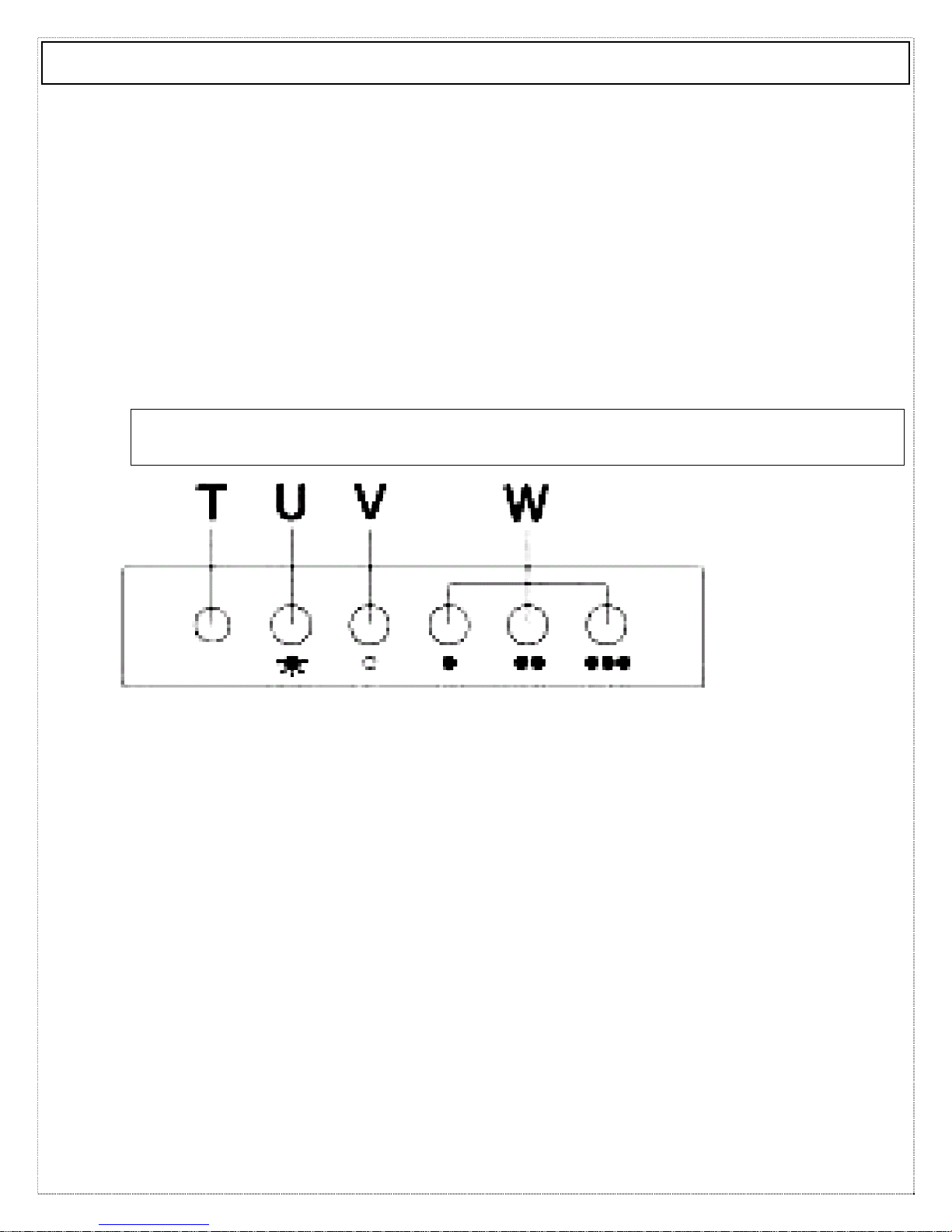
2) Find the CONTROL PANEL. It is located at the front of the
canopy. You have a Pushbutton control panel that looks like one
of those pictured below.
3) The CONTROL PANEL’s buttons all perform separate functions.
You will need to understand what these do before you attempt to
use your cooker hood.
* Note: The hood should be switched on at least as soon as you start
cooking.
Using your Baumatic Cooker Hood:
Button (from left on figure pictured above)
V - Motor Off button.
W (from left to right) –
. - Fan speed 1. Lowest fan speed.
.. - Fan speed 2. Middle fan speed.
… - Fan speed 3. Highest fan speed.
T - Motor ‘on/off’ light –This light indicates if hood is
on/off.
U - Light ‘on/off’ button – This button controls the
7
light.
Page 9

Cleaning your Baumatic Cooker Hood: Cleaning your Baumatic Cooker Hood:
IMPORTANT!:
Before cleaning, always ensure that you
have switched your cooker hood OFF at the omni-polar
switch, set at the wall from the cable:
Cleaning
 Clean the external parts with
mild liquid detergents on a
damp cloth.
 Never use abrasive powder,
corrosive solvents or brushes.
 Never insert pointed objects
into the motor’s protective grid.
 Only clean the control panel
and filter grill with a damp
cloth and delicate detergents.
________________________________________________
 Be sure to replace the
carbon filter at the
recommended intervals.
Build up could cause a
fire hazard.
 Never take out the
grease filters and
attempt to clean the
space above where they
are set.
Anti-Grease Grille
 Your cooker hood includes anti-grease grilles which
help absorb vapour-suspended grease particles to
protect your kitchen & furniture from greasy
residues.
 The metal grilles may become inflammable if they
become saturated with greasy residue.
9 To prevent this fire hazard, the grilles should be
cleaned regularly (depending on use) every 10-15
days and at least once a month in a dishwasher or in
hot water with normal washing-up detergent.
8
Page 10

Maintenance - Cleaning the Anti-grease Filters
First remove the grille by pulling down on it. Undo the
side catches.
You can now clean the anti-grease filter grilles.
9 Soak them for about one hour in hot water with a
grease-loosening detergent then rinse off thoroughly
with hot water.
9 Repeat the process if needed. Refit the grease grille
once it has dried.
To clean the grease filter grilles in your dishwasher:
9 Place the grease filter grilles in the dishwasher. Select the most
powerful washing programme and highest temperature.
9 Repeat the process, if necessary.
9 Refit the grease grilles when dry.
9 PLEASE NOTE: DISCOLOURATION OF THE GREASE
FILTER CAN TAKE PLACE WHEN CLEANED IN A
DISHWASHER, ETC. Do not worry about the slight
discolouration of the grille – its performance won’t
be affected.
Let the filter grilles dry thoroughly before refitting
them.
9
Page 11

Maintenance – Changing the Light Bulb and Carbon Filter
a) Changing the light bulb
9 Before changing the light bulb, ensure that the appliance is not live (i.e., ensure
that you have switched it off so that it’s in the ‘0’ position).
9 Remove the metal anti-grease filters (see Figure 2 below) and find the old bulb
located in the light fixture up inside the exposed canopy. Change the halogen bulb
only halogen spares with an E14 coupling, max. 50W.
using
* PLEASE NOTE - Defective bulbs should be replaced immediately.
9 Replace the metal anti-grease filters.
10
Page 12

Installing / Changing the Carbon Filter
______________________________________________________________________________________
Installing / Changing the Carbon Filter
.
Your Baumatic Cooker Hood uses CARBON FILTERS to
purify the air for the air recirculation function.
You will find two filters that will attach to both sides of
the fan motor (please see figures at bottom of page).
The active carbon filters must be replaced regularly, at least once
every three months (under normal working conditions – every 1015 days), to allow normal operation.
Before starting to fit the carbon filter, turn the omni-polar switch
to zero (0).
Changing the Carbon Filters
1) Press the handle of the metal grease
filter towards the rear part of the unit
until it is released from the front
housing, and remove it by pressing
downwards (Fig. 2 - above).
2) Remove the old carbon filters by
twisting them anticlockwise until they
unlatch from the sides of the motor.
3) Place the new carbon filters (which
have two fixing tongues), turning
clockwise so that the tongues latch
onto the motor’s sides. (Fig. 3 - left).
4) Reposition the anti-grease metallic filter grilles.
11
Page 13

INSTALLATION INSTRUCTIONS - Electrical INSTALLATION INSTRUCTIONS – Electrical Connection.
Before installation and usage, read all the instructions and make sure that the
voltage (V) and the frequency (Hz) indicated on the identification plate (found
inside your Cooker Hood) and all the data inside the appliance are exactly the
same as the voltage and frequency in your home.
NOTE: The manufacturer declines all responsibility in the event of failure to observe all the
accident-prevention regulations in force which are necessary for normal use and regular
operation of the electric system.
______________________________________________
ELECTRICAL CONNECTION
YYoouurr ccooookkeerr hhoooodd iiss iinntteennddeedd ffoorr ffiitttteedd aanndd ppeerrmmaanneenntt iinnssttaallllaattiioonn..
o The power cable must be
connected to the terminals
marked L (live) and N (neutral)
in the hood and fixed with a
cable clamp.
o The cooker hood’s power cable
must be fitted upstream from the
electrical connection using an
omni-polar switch with a contact
distance of at least 3mm.
NOTE: (UK only) WARNING – THIS APPLIANCE MUST NOT
BE EARTHED. It should only be
connected by a competent person using fixed wiring via a DOUBLE POLE SWITCHED FUSED
SPUR OUTLET.
We recommend that the appliance is connected by a qualified electrician who is a member
of the N.I.C.E.I.C. and who will comply with the I.E.E. and local regulations. The wires in
the mains lead are coloured in accordance with the following U.K. code:
Blue= Neutral, Brown = Live, Green/Yellow = Ground
If you can only find two wires in the cable (blue and brown), neither must be
• As the colours of the wires in the appliance’s mains lead may not
correspond with the coloured markings identifying the terminals in
your spur box, please proceed as follows:
__________________________________________________________
1) The BLUE
WIRE must be
connected to the
terminal marked ‘N’
(Neutral), or
coloured Black.
connected to the Earth terminal!
2)
The BROWN
WIRE must be
connected to the
terminal marked
‘L’ (‘Live’), or
coloured RED
(Fig. 7 – at left
)
3)
12
Page 14

INSTALLATION INSTRUCTIONS
–
PLEASE NOTE THAT YOU WILL HAVE
TO DECIDE BEFORE INSTALLING YOUR
COOKER HOOD THAT YOU CAN ADAPT
IT AS AN EXTRACTION FAN. PLEASE
SEE PAGE 18 NOW TO UNDERSTAND
CRUCIAL DIFFERENCES IN THESE.
NOTE: Your Baumatic Cooker Hood
should only be fitted from a ceiling.
Do NOT position it any less than
700 mm (70 cm) above the hob.
1) Take Plate A (Fig. 1), lean it against the ceiling and mark
the positions of the four holes ‘B’ (see Fig. 1) with a pencil.
Installing your Cooker Hood
:
The cooker hood must not
be fitted above stoves with a
radiant top plate.
:
We recommend that at least
two people install this hood.
2) Hole ‘C’ indicates the opposite side of the control part of the
hood (see Fig. 13)
3) Using an 8mm drill bit, make holes on the pencil marks you
have made.
4) Insert the dowels and attach plate ‘A’ with the 4 screws.
13
Page 15

INSTALLATION INSTRUCTIONS
–
5) Attach exit connector ‘D’ to the hood using the 2 provided
screws.
6) Connect to the room exhaust vent (Fig. 2).
Installing your Cooker Hood
7) Attach 2 of the 4
supporting angles ‘E’ to
the motor housing ‘S’ with
2 screws each; make sure
that the folds (E1) are
facing forwards (Fig. 3.1).
8) Attach the other 2
supporting angles (‘E’) to
the rear part of the motor
housing but this time the
folds (E2) must be facing
outwards (Fig. 3.2).
9) While you’re doing this, bear in
10) Install the motor frame
mind that you can alter the height
of the hood according to the
height of the angles’ support
holes. Just make sure that
whichever level of support hole
you choose to connect through
must be the same for all four
angles.
joining the 4 supporting angles
using the stiffener ‘F’ (positioned
as seen in Fig. 3) using 4 screws.
11) Insert the casing ‘H’ on the motor frame, keeping the vents
for the filtering operation towards the top and laterally.
14
Page 16

INSTALLATION INSTRUCTIONS
–
Installing your Cooker Hood
12) Then, insert casing ‘I’
over casing ‘H’ (Fig. 4).
13) Lift the entire unit, keeping it
slightly back from plate ‘A’
attached to the ceiling (see Fig.
5 & 5.1)
14) Then push it forward,
supporting it so that the vents
E1 and E2 of the 4 supporting
angles ‘E’ will insert themselves
into the front and lateral dowels
of plate ‘A’, provided with a
backstop (Fig. 5, 5.1, 5.1A &
5.1B).
15
Page 17

INSTALLATION INSTRUCTIONS
–
15) Now attach the motor
frame using 8 screws (see
Fig. 6 and 6.1).
Installing your Cooker Hood
16) Carry out the
electrical and (if using as
an extractor fan) air
exhaust tube connection.
17) Connect the
ventilation hose and
power lines.
18) Place the glass O
(Fig. 7 & 7.1) under the
frames.
19) Insert the 2 glass supports P (see Fig. 8) before pulling
them downwards.
16
Page 18

INSTALLATION INSTRUCTIONS
–
22) Then fix them using the
4 screws provided (Fig. 9).
23) Lift the lower part of
the hood ‘K’ (Fig. 9.1) and
insert it in the motor
frame with the tabs L1
going into the proper
dowels.
Installing your Cooker Hood
20) Now fix the glass,
screwing the 4 knobs ‘Q’
by hand.
21) Lift the casing ‘H’ up to
the ceiling, so that the
upper, lateral holes of the
casing correspond
with those of the plate.
24) Affix it with the 10 screws provided (Fig. 10, Fig. 10.1).
17
Page 19

Extraction / Air Purifier Modes of Operation
EXTRACTION OPERATION – Installation Instructions
 Ensure that you have fitted the
union (‘N’) to the upper part of the
hood using the packaged two
screws supplied inside the packing
(Fig. 1 – on right). Using a 125 mm
diameter pipe, connect the union
(N) on the upper part of the hood
(see Fig. 1) to the discharge outlet
for cooking vapours with a crosssection of at least 150 cm
 PLEASE NOTE: If there is no
discharge outlet and the hood is to
be fitted to an outside wall of the
building, make a hole in the wall
that is large enough to fit a wind
and rain-proof shutter with a cross
section of at least 150 cm
connect this to the outlet union of
the unit by means of a pipe.
_________________________ _______________________________________ __________________________________________ _____________________________________________ __________________________________________ _________________________
.
AIR PURIFIER OPERATION - Installation Instructions
The cooker hood can be converted to work as an air purifier in the
event that there is no provision for an external air discharge duct.
In this case, air is recycled through the vent ‘R’ (Fig. 1 – above).
When using the unit as an air purifier, you need to install two active
carbon filters to absorb cooking vapours (please see page 11).
Please note: For the air purifying function, you will need to connect
the spigot (‘N’ in fig. 1 above) to the connecting piece which is
provided. See figure on left.
².
² and
Please note: For the extraction function, you will
need to connect a 125 mm diameter outlet chimney
to the spigot ‘N’ in fig. 1 above. This pipe is not
provided with your cooker hood. See figure on left.
18
Page 20

Troubleshooting
If something has gone wrong with your Cooker Hood, checking
against this chart might keep you from having to call for service.
Symptom Solution
The cooker hood will not start!
The cooker hood is not working
effectively!
The cooker hood has switched off
during operation!
• Check that the hood is connected
to the electricity supply.
• Check that the fan speed control is
set properly.
• The fan speed is not set high enough.
• The grease filter is dirty.
• The kitchen is not ventilated well
enough.
• If the hood is set for recirculation,
check that the carbon filters have not
expired.
• If the hood is set for extraction, check
that the ducting and outlets are not
blocked.
• The safety cut-out device has been
tripped.
• Turn off the hob and then wait for the
device to reset.
• Note that if you have installed your
cooker hood too low, this will happen.
If it happens frequently, it will be
damaged.
19
Page 21

United Kingdom
Baumatic Ltd.,
Baumatic Buildings,
6 Bennet Road,
Reading, Berkshire
RG2 0QX
United Kingdom
Sales Telephone
(0118) 933 6900
Sales Fax
(0118) 931 0035
Service Telephone
(0118) 933 6911
Service Fax
(0118) 986 9124
Spares Telephone
(01235) 437244
Technical Advice Telephone
(0118) 933 6933
E-mail:
sales@baumatic.co.uk
technical@baumatic.co.uk
Website:
www.baumatic.co.uk
Republic of Ireland
01- 6266 798
Czech Republic
Baumatic CR spol s.r.o.
Amperova 495
46215, Librec
Czech Republic
+420 800 185 263
www.baumatic.cz
Slovak Republic
Baumatic Slovakia, s.r.o.
Skultetyho 1
831 04 Bratislava 3
Slovakia
+421 255 640 618
Germany
Baumatic Gmbh
Janderstrasse 9
Mannheim, 68199
Germany
+4962 112 9190
www.baumatic.de
Italy
Baumatic Italia S.R.L.
Via Caltana 129
Campodarsego (Padova), 35011
Italy
+3904 9920 2297
www.baumatic.it
Holland
Baumatic Benelux B.V.
Grindzuigerstraat 22
1333 MS ALMERE
The Netherlands
+3136 549 1555
www.baumatic.nl
20
Page 22

21
Page 23

Page 24

23
 Loading...