

Page 1

USER INSTRUCTION MANUAL
ISL94SS
Page 2

L3LI0320.doc
INSTRUCTIONS FOR THE INSTALLATION, MAINTENANCE AND USE OF THE HOOD MOD. K71
GENERAL
Before installing and/or using the hood, read all of the instructions carefully.
Before installing the hood, ensure that the voltage ( V ) and the frequency ( Hz ) indicated on the registration and technical data tag
attached to the inside of the appliance correspond with the voltage and frequency available in the place of installation.
IDENTIFICATION PLATE AND TECHNICAL DATA PLATE:
The identification plate and technical data plate are inside the appliance.
INSTALLATION
The accessories necessary for the installation of the hood can be found inside it. The hood is convertible and it can, therefore, be
installed in either the SUCTION or DEPURATION versions. In the event that the hood is used in its SUCTION version, connect the
opening (125 mm diameter) (Fig. 2) to an evacuation duct directly connected to the exterior and which has a minimum section of
150cm
2
. The hood’s lower surface must be positioned at a distance of at least 70cm from the cooking surface.
UNDER NO CIRCUMSTANCES SHOULD THE HOOD BE CONNECTED TO AN EXHAUST VENT OF OTHER APPLIANCES
WHICH USE ENERGY SOURCES OTHER THAN ELECTRICITY (water heaters – boilers – stoves – etc.). The appliance must not be
placed over stoves with upper radiating plates.
ELECTRICAL CONNECTION
The hood is designed to be installed in a fixed and permanent manner. For line voltage and frequency, consult the registration plate on
the inside of the appliance. The power cable (H05VV-F 2x0.75mm
2
type) connected to the clamps characterised with L (line), N
(neutral) of the hood and secured with a clamping screw, must be connected to a suitable and accessible power point carefully attached
by specialised and authorised personnel, who must follow the installation in compliance with the regulations and laws in force which
provide for the placement of an omnipolar switch before the electrical connection, with contact openings of at least 3 mm.
The manufacturer will not be held responsible if the existing Health and Safety regulations, which are necessary for the normal use and
standard operation of the electrical system, are not observed and complied with.
ONLY FOR U.K.:WARNING:THIS APPLIANCE MUST NOT BE EARTHED. This appliance must be connected by competent
person, using fixed wirin g via a DOUBLE POLE SWITCHED FUSED SPUR OUTLET.
We recommend that the appliance is connected by a qualified electrician,who is a member of the N.I.C.E.I.C.and who will comply with
the I.E.E.and local regolations.The wires in the mains lead are coloured in accordance with the following code:
Blue = Neutral, Brown = Live.
As the colours of the wires in the mains lead for the appliance, may not correspond with the coloured markings identifying the terminals
in your spur box, proceed as follows:1) The wire which is coloured blue must be connected to the terrninal marked N (Neutral), or
coloured Black.2) The wire which is coloured brown must be connected to the terminal marked L (Live), or coloured Red.
The manufacturer declines all responsibility in the event of failure to observe all the accident-prevention regulations in force which are
necessary for normal use and regular operation of the electric system.
TYPE OF OPERATION
Suction operation
Attach the connector D onto the upper part of the hood by means of the two screws which can be found in the little packet inside the
packaging (FIG. 2).
Connect same by means of a 125 mm tube to the steam and odours’ exhaust vent of the 150cm
2
small section.
In the event that the exhaust vent is not available, make an opening in the wall sufficient enough to attach an anti-rain/air lock, with a
minimum section of 150cm
2
, and connect same with a tube to the exhaust line of the appliance.
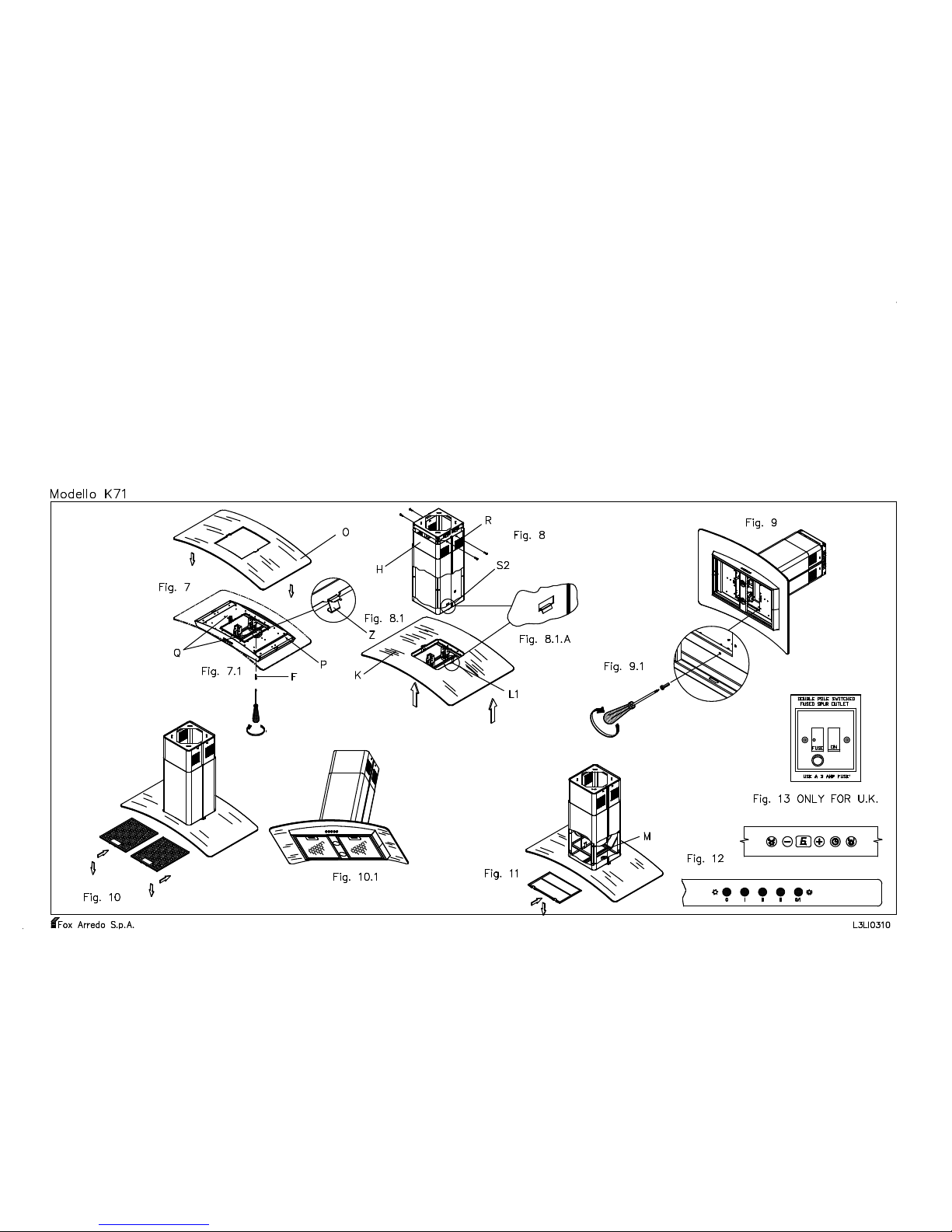
Air purifier operation
The hood can be transformed into a depuration device in the event of there being no possibility of discharging externally. In this case,
the air re-circulation is carried out by opening R (FIG. 7). For the operation of the hood in its depuration version, it is indispensable to
use an active carbon filter for absorbing cooking odours. The active carbon filter must be periodically changed – at least every three
months under standard operating conditions.
FITTING THE ACTIVE CARBON FILTERS
Before commencing with the insertion of the carbon filter, position the omnipolar switch in the 0 (OFF) position.
Exert pressure on the handle of the anti-grease metallic filter towards the back of the appliance, until same is released from the front
housing and thereafter remove it by exerting pressure towards the base (FIG. 10). Position the carbon filter in the dedicated seat of the
carbon filter support M (FIG. 9). The filter has two tabs at the back for positioning and two at the front for locking. To extract the
carbon filter, press the front tabs towards to the back and remove it by pulling towards the base. (Fig. 9). Re-position the anti-grease
metallic filters.
INSTRUCTIONS FOR ASSEMBLY
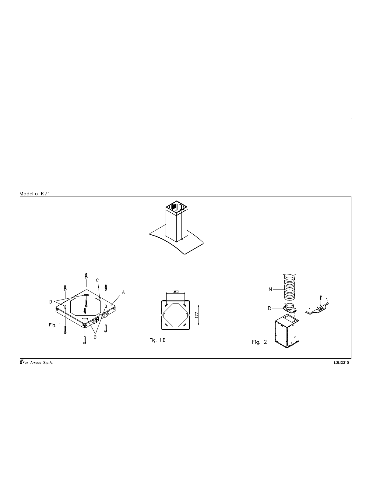
The hood is designed to be ceiling-mounted. The hood must be positioned at a distance of at least 70 cm from the cooking surface. Take
plate A (Fig. 1), lean it against the ceiling and mark the positions of the 4 holes B (see fig. 1); hole C indicates the part of the hood (see
fig. 10.1) which is opposite to the controls. Using an 8 mm drill bit, make holes on the marks referred to previously and thereafter insert the
dowels and attach plate A with the 4 screws (the dowels, screws and washers are all contained in the accessories bag). Attach exit
connector D to the hood using 2 screws (which have been provided) and connect to the room exhaust vent (Fig. 2). Attach 2 of the 4
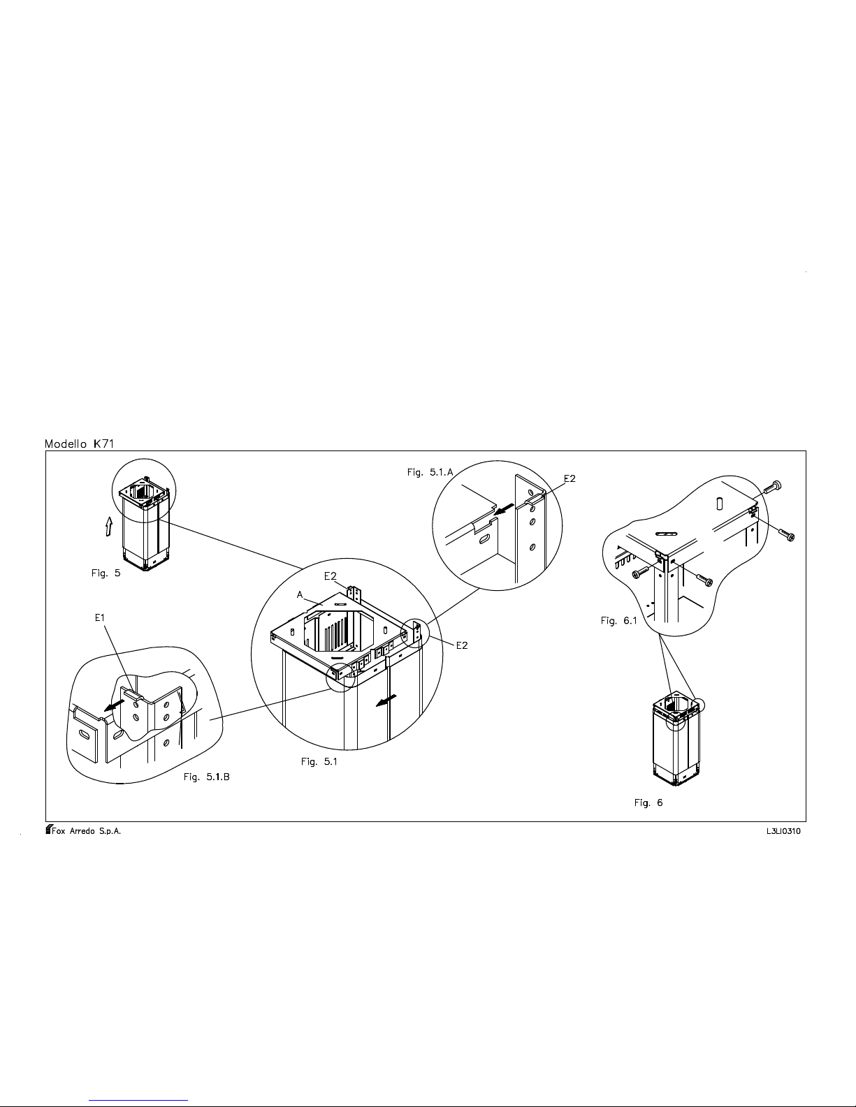
supporting angles E to the motor housing S with 2 screws each, ensuring that the folds E1 are facing forward (Fig. 3.1), thereafter affix the
other 2 supporting angles E to the rear part of the motor housing but this time the folds E2 must be facing outwards (Fig. 3.2). During this
phase, it is possible to regulate the predetermined height of the hood by fixing the 4 supporting angles E in the dedicated adjustment holes
on the hood.
Install the motor frame joining the 4 supporting angles by means of the stiffener F (positioned as per fig. 3) with 4 screws. Insert the casing
H on the motor frame keeping the vents for filtering operation towards the top and laterally; thereafter, insert casing I over casing H (fig.
4). Lift the entire unit, keeping it slightly back from plate A attached to the ceiling (Fig. 5 and Fig. 5.1). Thereafter push it forward
supporting it towards the ceiling in a way that the vents E1 and E2 of the 4 supporting angles E will insert themselves into the front and
lateral dowels of plate A provided with a backstop (fig. 5, 5.1, 5.1.A and 5.1.B.). Proceed then to attach the motor frame using 8 screws
(Fig. 6 and Fig. 6.1). Carry out the electrical and air discharge tube connection.
Remove the metal filters from the hood. Loosen both screws "F" (Fig. 7.1) (left and right respectively) and remove the fixing angle
identified with letter "Z" (Fig. 7.1) pulling it upwards.
Position glass "Q" on the upper side of the hood. Slide from above, through the horizontal slit corresponding to fixing angle "Z",
previously removed, until the short side of the fixing angle is placed horizontally on the glass. Attach fixing angle "Z" to the lower side of
the appliance, tightening again screws "F" in the hole and attaching them to the appliance.
Make sure that the fixing angle is securely attached by tightening hard. Insert back metal filters.
Connect the ventilation hose with connecting hose "N" (Fig. 2).
Lift the casing H up to the ceiling, so that the upper, lateral holes of the casing correspond with those of the plate, and thereafter affix them
using the 4 screws provided (Fig. 8.1). Lift the lower part of the hood K (Fig. 7) and insert it in the motor frame with the tabs L1 in the
proper dowels, thereafter affixing it with the 10 screws provided (Fig. 9, 9.1).
CONTROL PANEL
The commands panel (Fig. 11) is made up of a push-button panel which is situated on the front part of the hood and comprises :
3 push-buttons for motor control (first, second and third gear)
1 push-button for illuminating light;
1 push-button indicating motor off;
If the commands panel is made up of electronic commands, consult the attached instructions sheet.
MAINTENANCE
Before carrying out any operation, always make sure that the omnipolar switch is in the 0 (OFF) position.
a) Cleaning
Clean the external parts with a non-corrosive liquid detergent. Avoid using abrasive powders or brushes.
b) Changing the light bulb
Before replacing the light, make sure that the appliance is not powered up (position 0 (OFF) of the omnipolar switch). Extract the antigrease metal filters (Fig. 10). In the case of a halogen lamp, before replacing the lamp, remove the support ring of the glass by means of a
screwdriver. Replace the halogen lamp using only spare-parts with a G4 20W max. connection. Remount the glass protection, attaching it
with the suitable ring. In the case of dichroic 12V halogen lamp, replace the lamp using only spare-parts with a GU5.3 20W max.
connection. In the case of a 230V halogen lamp, replace the lamp using only spare-parts with an E14 50W max. connection.
Re-install the anti-grease metal filters.
c) Changing the carbon filter.
See fitting the carbon filter.
d) Cleaning the metal anti-grease filter.
The saturation of grease residues in the metallic filter could cause an increase in inflammability of the system. In order to prevent possible
fires, the metallic filter must be washed according to its use or at least every three months in a dishwasher or in hot water with normal
dishwasher detergent. After it has been well rinsed and dried, re-install the anti-grease metallic filter in its dedicated seat.
REMARKS
The cleaning must be carried out in accordance with the manufacturer's instructions, especially with regard to the deposits on the dirty
surfaces, against a possible risk of fire. Pay careful attention that the hot-plates are always covered in a manner which does not cause the
filter to overheat and to catch fire. Never fry leaving the pot unsupervised: the oil contained in the pot could overheat and catch fire. In the
case of used oil, the risk of spontaneous combustion is greater. It is absolutely forbidden to carry out open-fire cooking (eg. flambé). The
collected air must not be conveyed in a duct used for the discharge of smoke from appliances fed by energy sources other than electricity,
furthermore, adequate aeration must be provided in the room when the hood and appliances fed by energy sources other than electricity are
used at the same time. If the hood is used in suction mode, make sure that the discharge vent is in a good condition if it has not been used
for a long period of time. Remember to comply with existing local regulations and with the regulations of the competent authorities with
regards to the discharge of air to be evacuated when the hood is operating in suction mode. All the recommendations herein provided must
be scrupulously adhered to in order to avoid possible fires.
THE MANUFACTURER DECLINES ALL RESPONSIBILITY IN THE EVENT OF FAILURE TO OBSERVE THE INSTRUCTIONS
GIVEN HERE FOR INSTALLATION, MAINTENANCE AND SUITABLE USE OF THE HOOD.
Page 3

L3LI0320.doc
INSTRUCTIONS POUR L'INSTALLATION, L'ENTRETI EN ET L'UTILISATION DES HOTTE MOD. K71
GENERALITES:
Avant d'installer et/ou d'utiliser la hotte lire attentivement et intégralement les instructions.
Avant d'installer la hotte, s'assurer que la tension (V) et la fréquence (Hz) indiqués sur la plaquette du matricule et des données
techniques placée à l'intérieur de l'appareil correspondent bien à la tension et à la fréquence disponibles sur les lieux de l'installation.
PLAQUETTE MATRICULE ET DONNEES TECHNIQUES
La plaquette avec le matricule et les données techniques se trouve à l'intérieur de l'appareil.
INSTALLATION
Les accessoires nécessaires pour l’installation de la hotte se trouvent à l’intérieur de cette dernière. La hotte est convertible et peut donc
être installée dans la version d’ASPIRATION ou de DEPURATION.
Dans le cas où la hotte est utilisée dans la version d’ASPIRATION, il faut connecter l’ouverture (diamètre 125 mm) (fig.2) à une
conduite d’évacuation reliée directement à l’extérieur et ayant une section minimum de 150 cm².
Le plan inférieur de la hotte devra être distant d’au moins 70 cm du plan de cuisson.
EN AUCUN CAS LA HOTTE DOIT ETRE RELIEE A DES CHEMINEES D’EVACUATION D’AUTRES APPAREILS ALIMENTES
PAR UNE ENERGIE DIFFERENTE QUE CELLE ELECTRIQUE. (chauffe eau – chaudière – poêle etc.). L’appareil ne devra pas être
superposé à des poêles à plaques radiantes supérieures.
BRANCHEMENT ELECTRIQUE
La hotte est destinée à être installée de façon fixe et permanente. Pour le voltage de la ligne et la fréquence, consulter la plaquette
d’immatriculation située à l’intérieur de l’appareil. Le câble d’alimentation (type H05VV-F 2 x 0,75 mm²) connecté aux bornes
indiquées par L (ligne) , N (neutre) de la hotte et fixé par le serre-câble doit être connecté à un point d’alimentation adapté, accessible et
fixe par du personnel spécialisé et autorisé qui doit exécuter l’installation en respectant pleinement les normes et les lois en vigueur et
prévoyant en amont de la connexion électrique un interrupteur omnipolaire ayant une ouverture de contacts d’au moins 3 mm.
Le constructeur décline toute responsabilité au cas où toutes les normes pour la préventions des accidents du travail en vigueur et
nécessaires pour un emploi normal et un fonctionnement régulier de l’installation électrique ne seront pas respectées
TYPES DE FONCTIONNEMENT
ASPIRATION
Fixer le raccord D sur la partie supérieure de la hotte au moyen des deux vis qui se trouvent dans le sachet à l’intérieur de l’emballage
(FIG. 2)
Relier ce dernier à travers un tube de diamètre de 125 mm à la sortie d’évacuation des vapeurs et des odeurs de la section minimum de
150 cm².
Au cas où l’on ne dispose pas de conduite d’évacuation, faire dans le mur un trou de dimensions suffisantes et fixer une grille anti-pluie
et vent, de la section minimum de 150 cm². et relier cette dernière avec un tube au raccord de sortie de l’appareil.
ASSAINISSEMENT
La hotte peut être transformée en dépuration dans le cas où il n’existe aucune possibilité de sortie d’évacuation vers l’extérieur.
En ce cas la circulation de l’air est effectuée à partir de l’ouverture R (FIG.8). Pour le fonctionnement de la hotte en version de
dépuration il est indispensable d’utiliser un filtre à charbon actif pour l’absorption des odeurs de cuisine.
Le filtre à charbon actif doit être substitué périodiquement au moins une fois tous les trois mois pour un fonctionnement normal.
MISE EN PLACE DES FILTRES AU CHARBON ACTIF
Avant de commencer l’opération d’insertion du filtre à charbon, mettre l’interrupteur omnipolaire sur la position O (OFF).
Exercer sur la poignée du filtre métallique anti-gras une pression vers la partie postérieure de l’appareil, jusqu’à ce que ce dernier se
détache de son logement antérieur et ensuite l’enlever en exerçant une pression vers le bas (FIG.10).
Mettre le filtre à charbon dans le siège approprié du support du filtre à charbon M (FIG.11). Le filtre est doté de deux languettes
postérieures pour le positionnement et de deux languettes antérieures pour le blocage.
Pour extraire le filtre à charbon pousser les languettes antérieures vers la partie postérieure et l’enlever en tirant vers le bas. (Fig.11).
Remettre les filtres métalliques anti-gras.
INSTRUCTIONS POUR LE MONTAGE
La hotte est destinée à être montée au plafond. La hotte doit être distante d’au moins 70 cm du plan de cuisson.
Prendre la plaque A (fig.1), la poser au plafond et marquer la position des quatre trous B (voir fig.1) ; le trou C indique la partie opposée
aux commandes ( voir fig.10.1) de la hotte. Faire, sur les points de repère précédemment tracés, les trous en utilisant une mèche de
perceuse de 8 mm, ensuite insérer les chevilles et fixer la plaque A avec les quatre vis (les chevilles, les vis et les rondelles sont dans le
sachet des accessoires).
Fixer le raccord D avec 2 vis (en dotation) à la hotte et y relier le tuyau d’évacuation du local (Fig.2).
Fixer 2 des 4 équerres de soutien E au tiroir du moteur S avec 4 vis pour chacune en s’assurant que les cintres E1 soient orientés vers
l’avant (fig.3.1), fixer ensuite les deux autres équerres de soutien E sur la partie postérieure du tiroir du moteur en orientant cette fois,
les cintres E2 vers l’extérieur (fig.3.2). Pendant cette phase du montage il est possible de régler la hauteur préétablie de la hotte en fixant
les 4 équerres de soutien E dans les trous appropriés de réglage situés sur la hotte.
Monter le châssis du moteur en unissant les 4 équerres de soutien E au moyen du renfort F (situé comme indiqué sur la fig.3) à l’aide de 4 vis.
Insérer le carter H sur le châssis du moteur en gardant les fentes pour le fonctionnement filtrant vers le haut et latéralement, insérer ensuite
extérieurement au carter H le carter I (fig.4).
Lever le tout en le tenant légèrement en arrière par rapport à la plaque A fixée au plafond (Fig.5 et Fig.5.1). La pousser ensuite en avant en
la soutenant vers le plafond de façon que les cintres E1 et E2 des 4 équerres de soutien E aillent s’insérer dans les fentes antérieures et
latérales de la plaque munie d’arrêt (fig. 5,5.1,5.1A et 5.1B), fixer ensuite le châssis du moteur avec 8 vis (Fig.6 et Fig.6.1). Exécuter la
connexion électrique et celle du tuyau d’évacuation de l’air.
Enlever les filtres métalliques de la hotte. Desserrer les deux vis de fixage "F" (Fig.7.1) (respectivement celle de gauche et celle de droite)
et enlever l’angle de fixage marqué par la lettre "Z" (Fig.7.1), en le tirant vers le haut. Mettre le verre "Q" sur le plan supérieur de la hotte.
Introduire d’en haut à travers la fissure correspondante l’angle de fixage "Z", précédemment enlevé, jusqu’à ce que le coté court de l’angle
de fixage se mette horizontalement sur le verre. Fixer l’angle de fixage "Z" sur le coté inférieur du meuble, en revissant les vis "F" dans
leurs trous et en les reliant au meuble. Prêter beaucoup d’attention à ce que l’angle de fixage soit fixé solidement en le serrant avec force.
Remettre les filtres métalliques.
Relier le tuyau de ventilation au tuyau de raccord "N". (Fig.2)
Lever le carter H jusqu’au plafond, en le mettant de façon telle à faire correspondre les trous supérieurs du carter à ceux de la plaque, fixer
ensuite avec 4 vis en dotation (Fig.8).
Lever la partie basse de la hotte K (Fig.8.1) et la mettre sur le châssis du moteur avec les languettes L1 dans les fentes appropriées, la fixer
ensuite avec les 10 vis en dotation (Fig.9,9.1).
PANNEAU DE COMMANDE
L panneau de contrôle (Fig.12) est constitué par un panneau de boutons situé sur la partie frontale de la hotte et comprend :
3 boutons pour la commande du moteur (1
ier
–2
ième
– 3
ième
vitesse) ;
1 bouton pour la lampe d’illumination ;
1 bouton de moteur éteint
Si le panneau de contrôle est constitué par des commandes électroniques, il faut consulter le feuillet d’instructions joint.
ENTRETIEN
S’assurer toujours avant d’effectuer n’importe quelle opération que l’interrupteur omnipolaire soit sur la position O (OFF).
a) Nettoyage
Nettoyer les parties extérieures avec un détergent liquide non corrosif, éviter l’usage de poudres abrasives et de brosses.
b) Substitution de l’ampoule
Avant de changer l’ampoule s’assurer que l’appareil ne soit plus sous tension (position O (OFF) de l’interrupteur omnipolaire). Extraire les
filtres métalliques anti-gras (Fig.10). Au cas de présence de lampe halogène, avant de changer la lampe, enlever à l’aide d’un tournevis
l’anneau de soutien du verre. Substituer la lampe halogène en utilisant seulement des lampes avec une attache G4 20W max. Remonter le
verre de protection en le fixant avec l’anneau approprié. En cas d’usage de lampe halogène dichroïque 12V, il faudra la substituer
seulement par une lampe à attache GU5,3 20Wmax. En cas d’usage de lampe halogène 230V, il faudra la substituer seulement par une
lampe à attache E14 50Vmax.
Remettre les filtres métalliques anti-gras.
c) Substitution du filtre à charbon
Consulter le paragraphe relatif à l’insertion du filtre à charbon
d) Nettoyage du filtre métallique anti-gras
La saturation des résidus de gras dans le filtre métallique peut causer une augmentation de l’inflammabilité de ce dernier. Pour prévenir de
possibles incendies, le filtre métallique doit être lavé selon son usage et de toute façon une fois tous les trois mois dans le lave-vaisselle ou
avec de l’eau chaude et de normaux détergeants pour vaisselle. Après l’avoir soigneusement rincé et essuyé, remettre le filtre métallique
anti-gras dans son siège approprié.
AVERTISSEMENTS
Le nettoyage doit être effectué selon les instructions du constructeur spécialement pour ce qui concerne le dépôt sur les superficies sales
afin de prévenir des possibles risques d’incendie.
Faire toujours attention que les « feux » soient toujours couverts de façon telle à ne pas procurer de surchauffe du filtre de la hotte.
Ne jamais frire en laissant la casserole sans surveillance : l’huile contenue dans la casserole pourrait se surchauffer et prendre feu. En cas
d’huile réutilisé le risque de combustion spontanée est plus élevé.
Il est absolument interdit d’utiliser des techniques de cuisson qui produisent un développement de flamme sous la hotte (par exemple :
flambé). L’air recueilli ne doit pas être convoyé dans une conduite utilisée comme sortie d’évacuation de fumée d’appareils de cuisine
alimentés par une énergie différente que celle électrique, en outre une adéquate aération du local doit être prévue quand la hotte et des
appareils de cuisine alimentés par une énergie différente que celle électrique sont utilisés en même temps.
Si la hotte est utilisée dans sa version d’aspiration, s’assurer des conditions de la cheminée d’évacuation, au cas où cette dernière soit
restée inutilisée pendant longtemps.
Se rappeler toujours de prêter attention aux normes locales en vigueur et aux prescriptions des autorités compétentes pour ce qui concerne
la sortie de l’air à évacuer lors du fonctionnement en aspiration de la hotte.
Toutes les suggestions données à ce propos doivent être scrupuleusement observées afin d’éviter de possibl es incendies.
LE CONSTRUCTEUR DECLINE TOUTES RESPONSABILITES SI LES INDICATIONS DECRITES CI-DESSUS EN MATIERE
D’INSTALLATION, D’ENTRETIEN ET D’UTILISATION APPROPRIEE DE LA HOTTE NE SERONT PAS OBSERVEES.
Page 4

L3LI0320.doc
ISTRUZIONI PER L'INSTALLAZIONE, LA MANUTENZIONE E L'US O DELLA CAPPA MOD. K71
GENERALITA'
Prima di installare e/o usare la cappa leggere attentamente ed integralmente le istruzioni.
Prima di installare la cappa assicurarsi che la tensione ( V ) e la frequenza ( Hz ) indicati sulla targhetta matricola e dati tecnici posta
all'interno dell'apparecchio corrisponda alla tensione e frequenza disponibili nel luogo d'installazione.
Targhetta matricola e da ti tecnici.
La targhetta matricola e dati tecnici si trovano all'interno dell'apparecchio.
INSTALLAZIONE
Gli accessori necessari all'installazione della cappa si trovano all'interno della stessa.
La cappa é convertibile e quindi può essere installata nella versione ASPIRANTE o DEPURANTE.
Nel caso in cui la cappa sia usata nella versione ASPIRANTE, collegare l'apertura ( diametro mm 125 ) (Fig. 2) ad un condotto di
evacuazione collegato direttamente con l'esterno ed avente una sezione minima di 150 cm
2
.
Il piano inferiore della cappa deve distare almeno 70cm. dal piano cottura.
IN NESSUN CASO LA CAPPA DEVE ESSERE COLLEGATA A CAMINI DI SCARICO DI ALTRI APPARECCHI ALIMENTATI
CON ENERGIA DIVERSA DA QUELLA ELETTRICA ( scaldabagni - caldaie - stufe - ecc. ). L'apparecchio non deve essere
sovrapposto a stufe con piastra radiante superiore.
COLLEGAMENTO ELETTRICO
La cappa è destinata ad essere installata in modo fisso e permanente. Per tensione di linea e frequenza consultare la targa matricola posta
all'interno dell'apparecchio. Il cavo d'alimentazione (tipo H05VV-F 2x0.75mm2) collegato ai morsetti contraddistinti con L (linea), N
(neutro) della cappa e fissato con il serracavo, deve essere collegato ad un idoneo ed accesibile punto di alimentazione fisso a cura del
personale specializzato ed autorizzato che deve eseguire l'installazione nel rispetto delle norme e leggi vigenti prevedendo a monte del
collegamento elettrico un interruttore onnipolare con apertura dei contatti di almeno 3mm.
Il costruttore declina ogni responsabilità nel caso non siano osservate tutte le norme antinfortunistiche vigenti e necessarie al normale
esercizio e regolare funzionamento dell'impianto elettrico.
TIPI DI FUNZIONAMENTO
Aspirante
Fissare il raccordo D sulla parte superiore della cappa tramite le due viti che si trovano nel sacchetto all'interno dell'imballo ( FIG. 2 ).
Collegare il medesimo mediante un tubo di diametro 125 mm allo scarico d'evacuazione vapori e odori della sezione minima di 150 cm2
Nel caso non si disponga di detto condotto d’evacuazione, praticare sul muro un foro sufficiente a fissare una serranda antipioggiavento, della sezione minima di 150 cm2 e collegare la medesima con un tubo al raccordo d'uscita dell'apparecchio.
Depurante
La cappa può essere trasformata in depurante nel caso non esista alcuna possibilità di scarico verso l'esterno.
In questo caso il ricircolo dell'aria é effettuato dall'apertura R ( FIG. 8 ) Per il funzionamento della cappa in versione depurante é
indispensabile l'uso di un filtro di carbone attivo per l'assorbimento degli odori di cottura.
Il filtro carbone attivo deve essere sostituito periodicamente almeno ogni tre mesi per un normale funzionamento.
INSERIMENTO DEI FILTRI DI CARBONE ATTIVO
Prima di iniziare l'operazione di inserimento del filtro carbone, posizionare l'interruttore onnipolare sulla posizione 0 (OFF).
Esercitare sulla maniglia del filtro metallico antigrasso una pressione verso la parte posteriore dell'apparecchio, finché il medesimo si
sblocca dall'alloggiamento anteriore e quindi toglierlo esercitando una pressione verso il basso ( FIG. 10 ).
Posizionare il filtro carbone nell'apposita sede del supporto filtro carbone M ( FIG: 11). Il fltro è dotato di due linguette posteriori per il
posizionamento e due anteriori di bloccaggio.
Per estrarre il filtro carbone premere le linguette anteriori verso la parte posteriore e rimuoverlo tirando verso il basso. (Fig. 11).
Riposizionare i filtri metallici antigrasso.
ISTRUZIONI PER IL MONTAGGIO
La cappa è destinata al montaggio a soffitto. La cappa deve distare almeno 70 cm dal piano cottura.
Prendere la placca A ( fig.1), appoggiarla al soffitto e segnare la posizione dei 4 fori B ( vedi fig.1.); Il foro C indica la parte opposta ai
comandi (vedi fig.10.1) della cappa. Praticare, sui riferimenti precedentemente tracciati, i fori utilizzando una punta da trapano da 8 mm
quindi inserire i tasselli e fissare la placca A con le 4 viti ( Tasselli, viti, e rondelle sono nel sacchetto accessori ).
Fissare il raccordo D con 2 viti (in dotazione) alla cappa e collegarci il tubo d’evacuazione del locale (Fig.2).
Fissare 2 dei 4 angolari di sostegno E al cassetto motore S con 4 viti per ciascuno, assicurandosi che le pieghe E1 siano orientate in
avanti (Fig.3.1) , quindi fissare gli altri 2 angolari di sostegno E alla parte posteriore del cassetto motore orientando, questa volta, le
pieghe E2 verso l’esterno (Fig.3.2). In questa fase è possibile regolare l'altezza predeterminata della cappa fissando i 4 angolari di
sostegno E negli appositi fori di regolazione posti sulla cappa.
Montare il telaio motore unendo i 4 angolari di sostegno E tramite il rinforzo F (posizionato come in fig.3) con 4 viti.
Inserire il carter H sul telaio motore tenendo le feritoie per il funzionamento filtrante verso l’alto e lateralmente, quindi inserire
esternamente al carter H, il carter I (Fig.4).
Alzare il tutto tenendolo leggermente arretrato rispetto alla placca A fissata al soffitto ( Fig.5 e Fig.5.1). Quindi spingerla in avanti
sostenendolo verso il soffitto in modo che le pieghe E1 ed E2 dei 4 angolari di sostegno E vadano ad inserirsi nelle feritoie anteriori e
laterali delle placca A provviste di fermo (fig.5, 5.1, 5.1.A e 5.1.B), quindi fissare il telaio motore con 8 viti (Fig.6 e Fig.6.1). Eseguire il
collegamento elettrico e del tubo d’evacuazione del aria.
Rimuovere i filtri metallici dalla cappa. Allentare entrambe le viti di fissaggio F (Fig. 7.1) (rispettivamente quella di sinistra e di destra) e
rimuovere l'angolo di fissaggio contrassegnato con la lettera Z (Fig.7.1), tirandolo verso l'alto. Posizionare il vetro Q sul ripiano superiore
della cappa. Introdurre dall'alto attraverso la fessura corrispondente l'angolo di fissaggio Z, precedentemente tolto, finché il lato corto
dell'angolo di fissaggio sia posizionato orizzontalmente sul vetro. Fissare l'angolo di fissaggio Z al lato inferiore del mobile, avvitando
nuovamente le viti F nel foro e collegandole al mobile. Prestare attenzione affinché l'angolo di fissaggio sia fissato saldamente
stringendolo con forza. Reinserire i filtri metallici.
Collegare il tubo di ventilazione con il tubo di raccordo N. (Fig. 2)
Alzare il carter H fino al soffitto, mettendo in corrispondenza i fori laterali superiori del carter con quelli della placca, quindi fissare con 4
viti in dotazione (Fig.8).
Alzare la parte bassa della cappa K (Fig.8.1) e inserirla sul telaio motore con le linguette L1 nelle apposite feritoie, quindi fissarla con le
10 viti in dotazione (Fig.9,9.1).
PANNELLO COMANDI
Il pannello comandi (Fig. 12) è costituito da una pulsantiera situata nella parte frontale della cappa e comprende:
3 tasti per il comando del motore (1a - 2a - 3a velocita');
1 tasto per lampade d'illuminazione;
1 tasto di motore spento
Se il pannello comandi è costituito da comandi elettronici, consultare il foglio istruzioni allegato.
MANUTENZIONE
Assicurarsi sempre prima di effettuare qualsiasi operazione che l'interruttore onnipolare sia nella posizione 0 (OFF).
a) Pulizia
Pulire le parti esterne con detersivo liquido non corrosivo, evitare l'uso di polveri abrasive o di spazzole.
b) Sostituzione lampada
Prima di sostituire la lampada assicurarsi che l'apparecchio non sia sotto tensione (posizione 0 (OFF) dell'interruttore onnipolare). Estrarre
i filtri metallici antigrasso (Fig. 10). Nel caso di faro alogeno, prima di sostituire la lampada, togliere con l'aiuto di un cacciavite l'anello di
supporto del vetro. Sostituire la lampada alogena usando solo ricambi con attacco G4 20Wmax. Rimontare il vetro di protezione fissandolo
con l'apposito anello. Nel caso di lampada alogena dicroica 12V, sostituire la lampada usando solo ricambi con attacco GU5.3 20Wmax.
Nel caso di lampada alogena 230V, sostituire la lampada usando solo ricambi con attacco E14 50Wmax.
Riposizionare i filtri metallici antigrasso.
c) Sostituzione filtro carbone
Vedi inserimento filtro carbone.
d) Pulizia filtro metallico antigrasso
La saturazione dei residui di grassi nel filtro metallico puo' causare un aumento dell’infiammabilità' del medesimo. Al fine di prevenire
possibili incendi, il filtro metallico va lavato in funzione all'uso e comunque ogni tre mesi in lavastoviglie o in acqua calda con normali
detersivi per stoviglie. Dopo averlo accuratamente sciacquato ed asciugato, riposizionare il filtro metallico antigrasso nell'apposita sede.
AVVERTENZE
La pulitura deve essere effettuata secondo le istruzioni del costruttore specialmente riguardo ai depositi sulle superfici insudiciate contro
un possibile rischio di incendio.
Prestare attenzione che i fuochi siano sempre coperti in modo tale da non procurare surriscaldamento al filtro della cappa.
Non friggere mai lasciando la pentola senza sorveglianza: l'olio contenuto nella pentola può surriscaldarsi e incendiarsi. Nel caso d'olio
usato il rischio di autocombustione è più' elevato.
E' assolutamente vietato eseguire cotture con sviluppo di fiamma sotto la cappa (es. flambee ). L'aria raccolta non deve essere convogliata
in un condotto usato per lo scarico di fumi di apparecchi alimentati con energia diversa da quell'elettrica, inoltre deve essere prevista
un'adeguata aerazione del locale quando la cappa e apparecchi alimentati con energia diversa da quell'elettrica vengono usati
contemporaneamente.
Se la cappa è utilizzata nella versione aspirante, assicurarsi delle condizioni del camino di scarico, nel caso quest'ultimo sia rimasto
inutilizzato per lungo tempo.
Ricordarsi di prestare attenzione alle norme vigenti locali e alle prescrizioni delle autorità competenti in merito allo scarico dell'aria da
evacuare nel funzionamento aspirante della cappa.
Tutti i suggerimenti dati a riguardo devono essere scrupolosamente osservati al fine di evitare possibili incendi
IL COSTRUTTORE DECLINA OGNI RESPONSABILITA' NEL CASO NON VENGANO OSSERVATE LE INDICAZIONI QUI
SOPRA DESCRITTE IN MERITO AD INSTALLAZIONE. MANUTENZIONE ED IDONEO UTILIZZO DELLA CAPPA.
Page 5
L3LI0320.doc
ANWEISUNG ZUR INSTALLATION, WARTUNG UND GEBRAUCH DER DUNSTABZUGSHAUBE MODELL K 71
ALLGEMEINES
Vor der Installation bzw. der Verwendung der Dunstabzugshaube, sind die Anweisungen aufmerksam und zur Gänze zu lesen. Vergewissern
Sie sich vor der Installation, daß die Spannung (V) und die Frequenz (Hz), die auf dem im Geräteinneren angebrachten Typenschild und in
den technischen Daten angeführt sind, der Spannung und der Frequenz entsprechen, die am Installationsort verfügbar sind.
Typenschild und technische Daten.
Das Typenschild und die technischen Daten befinden sich im Geräteinneren.
INSTALLATION
Das für die Installation der Abzugshaube erforderliche Zubehör befindet sich im Inneren des Gerätes. Die Haube ist verwandelbar und
kann daher in der Version mit ABLUFTBETRIEB oder mit UMLUFTBETRIEB installiert werden.
Montage siehe Montageanleitung-.
Im ABLUFTBETRIEB einen Abluftkanal mit dem Durchmesser 125mm verwenden. Dieser Abluftkanal muß durchgehend dieser Größe
entsprechen.
DIE HAUBE DARF KEINESFALLS AN ABLUFTKAMINE ANDERER GERÄTE ANGESCHLOSSEN WERDEN, DIE MIT EINER
ANDEREN ENERGIE ALS MIT DER ELEKTRISCHEN GESPEIST WERDEN (Boiler - Heizungen - Öfen - etc.). Das Gerät darf nicht
über Öfen mit Heizplatten installiert werden.
ELEKTRISCHER ANSCHLUSS
Die Haube ist zur fixen und ständigen Installation bestimmt. Hinsichtlich der Leitungsspannungen und der Frequenz ist das Typenschild
zu konsultieren, das sich im Geräteinneren befindet. Das an die mit L (Leitung) und N (Nulleiter) gekennzeichneten Klemmen
angeschlossene und mit der Kabelschelle fixierte Stromkabel (Typ H05VV-F 2x0,75mm²) muß an einer geeigneten und zugänglichen
fixen Stromversorgungsstelle durch autorisiertes Fachpersonal angeschlossen werden. Dieses hat die Aufgabe, die Installation unter
Einhaltung der Normen und geltenden Gesetze durchzuführen und dem elektrischen Anschluß einen allpoligen Schalter mit
Kontaktöffnungen von mindestens 3 mm vorzuschalten.
Der Hersteller lehnt jede Haftung ab, wenn sämtliche gültigen und für den normalen und regulären Betrieb erforderlichen Vorschriften
nicht eingehalten werden.
FUNKTIONSARTEN
Absaugend
Das Verbindungsteil D an den oberen Teil der Haube mittels zwei Schrauben, welche sich im inneren der Verpackung befinden,
befestigen (Fig. 2), Dieses mit einem 125 mm Rohr an die Geruch-und Dampfabsaugungsvorrichtung von mindestens 150cm
2
Durchmeser anschliessen. Sollte ein derartiges Absaugrohr nicht vorhanden sein, ein genügend grosses Loch in die Wand bohren, einen
Wind-Regenschutz von mindestens 150cm
2
Durchmesser anbringen und diesen durch ein Rohr mit dem Ausgangsanschluss des Gerätes
verbinden.
Reinigend
Die Haube kann bei Fehlen einer Ablassvorrichtung nach aussen als reinigend eingesetzt werden.
In diesem Falle erfolgt der Luftkreislauf durch die Öffnung R (Fig. 8). Zur Reinigungsfunktion der Haube muss ein Aktivkohlefilter zur
Absaugung der Kochgerüche eingesetzt werden. Zur normalen Funktion muss der Aktivkohlefilter von Zeit zu Zeit, mindestens jedoch
alle 3 Monate ausgetauscht werden .
ANBRINGUNG DER AKTIVKOHLEFILTER
Vor Beginn der Anbringung des Aktivkohlefilters, den Schalter auf Position 0 (OFF) stellen. Auf den Hebel des metallischen
Antifettfilters leichten Druck gegen den hinteren Teil des Gerätes, bis zum loslösen des Filters aus seinem vorderen Sitz ausüben und
diesen folglich mit leichtem Druck nach unten (Fig.10) entnehmen.
Den Aktivkohlefilter in den eigens dafür vorgesehenen Sitz M einführen (Fig.11). Am Filter sind zwei hintere Laschen zur Anbringung
und zwei vordere Laschen zum blockieren vorgesehen.
Um den Aktivkohlefilter zu entfernen die vorderen Laschen nach hinten drücken und den Filter nach unten ziehend entfernen (Fig. 11).
MONTAGEANLEITUNGEN
Die Haube ist zur Deckenmontage geeignet und muss mindestens 70 cm vom Kochfeld entfernt sein.
Die Platte A (Fig.1) gegen die Decke halten und die Position der 4 Ösen B (Fig.1) anzeichnen. Öse C steht den Bedienungstasten der
Haube gegenüber (Fig. 10.1). Mit einer Bohrmaschine und Spitze 8mm an den angezeichneten Stellen bohren, Dübel einführen und die
Platte A mit 4 Schrauben befestigen (Dübel, Schrauben und Unterlegscheiben befinden sich in der Zubehörtüte).
Das Anschlusstück D mit zwei (beiliegenden) Schrauben an die Haube befestigen und das Absaugrohr (Fig.2) anschliessen.
2 der 4 Stützwinkel E an den Motorbehälter S mit jeweils 4 Schrauben befestigen und sicherstellen, dass die Falten E1 nach vorne
(Fig.3.1) gerichtet sind; folglich die weiteren 2 Stützwinkel E an den vorderen Teil des Motorbehälters befestigen und die Falten E2
nach aussen richten (Fig.3.2). Nun ist die vorgegebene Höheneinstellung der Haube durch befestigen der 4 Stützwinkel E an die
Einstellungsösen an der Haube möglich.
Den Motorrahmen durch Einigung der 4 Stützwinkel E mit dem Versteifungsteil F (wie in Fig, 3 positioniert) mit 4 Schrauben
anbringen. Das Gehäuse H in den Motorrahmen einführen, die Schlitze der Filtrierungsfunktion seitlich nach oben richten und
äusserlich des Gehäuses H, das Gehäuse I (Fig.4) einführen.
Alles mit leichter Neigung nach hinten gegenüber der, an der Decke befestigten Platte A heben (Fig. 5 und Fig. 5.1). Folglich nach vorne
drücken und gegen die Decke halten, sodass die Falten E1 und E2 der 4 Stützwinkel E in die vorderen und seitlichen Schlitze (mit
Blockierung) der Platte A (Fig. 5, 5.1, 5.1A und 5.1B) eingeführt werden können. Den Motorrahmen schliesslich mit 8 Schrauben (Fig. 6
und Fig. 6.1) befestigen. Den elektrischen Anschluss und den Anschluss des Luftabsaugrohrers vornehmen.
Die Metallfilter aus der Hasube entfernen. Beide Befestigungsschrauben „F“ (Fig. 7.1 rechts und links) lösen und den, mit dem Buchstaben
„Z“ gekennzeichneten Befestigungswinkel mit Druck nach oben entfernen. Die Scheibe „Q“ auf die obere Fläche der Haube legen. Den
Befestigungswinkel „Z“, welcher vorher entnommen wurde, von oben durch den entsprechenden Schlitz einführen, bisdass die kurze Seite
des Befestingswinkels horizzontal auf der Scheibe liegt. Den Befestingunswinkel „Z“ am unteren Möbelteil befestigen und erneut die
Schrauben „F“ in die Öse schrauben und am Möbelstück befestigen. Sicherstellen, dass der Befestingungswinkel kraftvoll befestigt wurde.
Das Lüftungsrohr an das Verbindungsrohr „N“ anschliessen (Fig. 2).
Das Gehäuse H bis zur Decke heben indem die seitlichen oberen Ösen des Gehäuses mit jenen der Platte übereinstimmen müssen, mit 4
Schrauben befestigen (Fig.8).
Den unteren Teil der Haube K heben (Fig. 8.1) und mit den Laschen L1 in die vorgesehen Schlitze im Motorrahmen
SCHALTUNG
Elektronische Schaltung
:
Wann die Haube die elektronische Schaltung hat, sehen Sie bitte die beiliegende Gebrauchsanweisung.
Druckknopfschaltung
:
Das Steuerpult aus einer Druckknopftafel am Vorderteil der Haube besteht, umfaßt sie:
3 Tasten für die Motorsteuerung (1. - 2. - 3. Geschwindigkeit);
1 Beleuchtungstaste;
1 Taste für abgeschalteten Motor.
WARTUNG
Vergewissern Sie sich vor jeder Wartungsarbeit, daß der allpolige Schalter auf 0 (OFF) positioniert wird.
a) Reinigung
Die Außenteile mit einem milden Reinigungsmittel reinigen. Vermeiden Sie die Verwendung von Scheuermitteln oder Bürsten.
b) Lampenaustausch
Vergewissern Sie sich vor dem Austauschen der Lampe, daß das Gerät nicht unter Spannung steht (Position 0 (OFF) des allpoligen
Schalters). Nehmen Sie die Metall-Fettfilter heraus (ABB. 10). Bei Halogenscheinwerfern ist vor dem Austausch der Lampe, mit einem
Schraubenzieher der Stützring des Glases zu entfernen. Tauschen Sie die Halogenlampe nur unter der Verwendung von Ersatzteilen mit
der Schraubfassung G4 20W max. aus. Montieren Sie erneut das Schutzglas und befestigen Sie es mit dem entsprechenden Ring. Bei
dichroitischer Halogenlampe zu 12 V ist die Lampe nur unter der Verwendung von Ersatzteilen mit Schraubfassung GU5.3 20W max. zu
ersetzen. Bei Halogenlampen zu 230 V darf die Lampe nur unter der Verwendung von Ersatzteilen mit Schraubfassung E14 50W max.
verwendet werden. Erneut die Metall-Fettfilter in ihrem Sitz positionieren.
c) Ersatz des Kohle-Filters
Siehe Einsetzen des Kohle-Filters.
d) Reinigung des Metall-Fettfilters
Die Sättigung der Fettreste im Metall-Fettfilter kann eine Steigerung der Entzündbarkeit desselben verursachen. Um einer möglichen
Brandgefahr vorzubeugen, muß der Metallfilter je nach Verwendung, aber alle min. drei Wochen im Geschirrspüler oder mit heißem
Wasser mit normalem Geschirrspülmittel gereinigt werden. Nachdem er sorgfältig nachgespült und getrocknet wurde, ist er an den
entsprechenden Sitz wieder zurückzugeben.
WICHTIG
Die Reinigung muß entsprechend den Anweisungen des Herstellers insbesondere in Hinblick auf die Ablagerungen auf den beschmutzten
Flächen zum Schutz vor möglicher Brandgefahr durchgeführt werden.
Es ist darauf zu achten, daß die Feuerstellen immer abgedeckt sind, damit keine Überhitzung des Haubenfilters verursacht wird.
Fritieren Sie niemals, ohne den Topf aus den Augen zu lassen: das Öl in der Pfanne kann sich überhitzen und entflammen. Bei
Verwendung von bereits verwendetem Öl ist das Risiko der Selbstverbrennung erhöht.
Es ist absolut verboten, mit offener Flamme unter der Haube zu kochen (z.B. Flambieren).
Die gesammelte Luft darf nicht in einem Rohr abgeführt werden, das für den Rauchabzug von Geräten, die nicht elektrisch betrieben
werden, bestimmt ist. Außerdem muß eine entsprechende Entlüftung des Raumes vorgesehen sein, wenn die Haube und andere nicht mit
elektrischer Energie betriebenen Geräte gleichzeitig verwendet werden.
Gilt nur für Deutschland: Wenn die Haube und die Geräte, die nicht mit elektrischer Energie betrieben werden, gleichzeitig in Betrieb
genommen werden, darf der Unterdruck des Raumes nicht 4 Pa (4 x 10 -5) überschreiten.
Wird die Haube mit Abluftbetrieb verwendet, ist der Zustand des Abluftkamines zu prüfen, wenn dieser für längere Zeit nicht benützt wurde.
Erinnern Sie sich außerdem daran, die örtlichen gültigen Normen und den Vorschreibungen der zuständigen Behörden hinsichtlich der
abzuleitenden Luft zu beachten, wenn das Gerät mit Abluftbetrieb verwendet wird.
Sämtliche Ratschläge müssen strengstens eingehalten werden, damit mögliche Brände vermieden werden.
DER HERSTELLER LEHNT JEDE HAFTUNG AB, WENN DIE HIER BESCHRIEBENEN ANWEISUNGEN ZUR
INSTALLATION, WARTUNG UND EINER GEEIGNETEN VERW ENDUNG DER HAUBE NICHT BEACHTET WERDEN.
Page 6

L3LI0320.doc
INSTRUCCIONES PARA LA INSTALACION, EL MANTENIMIENTO Y EL EMPLEO DE LAS CAMPANAS MOD. K71
GENERALIDADES
Antes de instalar y/o utilizar la campana lea con atención y en su totalidad las instrucciones.
Antes de instalar la campana asegúrese de que la tensión (V) y la frecuencia (Hz) que se indican en la placa de matrícula y datos técnicos
situada dentro del aparato coinciden con la tensión y la frecuencia disponibles en el lugar donde se instala.
Placa matrícula y datos técnicos.
La placa de matrícula y datos técnicos se encuentra dentro del aparato.
INSTALACION
Los accesorios necesarios para la instalación de la campana se encuentran dentro de ésta.
La campana es convertible y por tanto puede instalarse en la versión ASPIRANTE o DEPURANTE.
Si se utiliza en la versión ASPIRANTE, conecte la apertura (diámetro 125 mm.) (Fig. 2) a un conducto de evacuación conectado
directamente con el exterior y que posea una sección mínima de 150 cm².
El plano inferior de la campana debe distar al menos 70 cm. de la encimera.
LA CAMPANA NO DEBE CONECTARSE EN NINGÚN CASO A CONDUCTOS DE DESCARGA DE OTROS APARATOS
ALIMENTADOS CON ENERGÍA QUE NO SEA ELÉCTRICA (calentadores, calderas, estufas, etc.). El aparato no debe colocarse
encima de estufas con placa radiante superior.
CONEXION ELECTRICA
La campana se ha creado para instalarse de forma fija y permanente. Para la tensión de línea y la frecuencia consulte la placa de
matrícula situada dentro del aparato. El cable de alimentación (tipo H05VV-F 2x0,75 mm²) conectado a los bornes marcados con una L
(línea), N (neutro) de la campana y fijado con la abrazadera, debe conectarse a un punto de alimentación fijo apropiado y accesible
determinado por personal especializado y autorizado que debe efectuar la instalación respetando las normas y leyes en vigor
predisponiendo antes de la conexión eléctrica un interruptor omnipolar con apertura de los contactos de al menos 3 mm.
El fabricante declina cualquier responsabilidad en caso de que no se respetaran todas las normas contra accidentes en vigor y necesarias
para el funcionamiento normal y regular de la instalación eléctrica.
TIPO DE FUNCIONAMIENTO
Aspirante
Fije la unión en D a la parte superior de la campana mediante los dos tornillos que se encuentran en la bolsa dentro del embalaje (FIG.
2).
Conecte ésta mediante un tubo de 125 mm. de diámetro a la descarga de vapores y olores de una sección mínima de 150 cm².
Si no se dispone de este conducto de evacuación, haga en la pared un orificio capaz de fijar un registro contra la lluvia y el viento, de
una sección mínima de 150 cm² y conecte éste con un tubo a la unión de salida del aparato.
Depurante
La campana puede transformarse en depurante si hay posibilidad de descarga al exterior.
En este caso el reciclaje del aire se efectúa a través de la apertura R (FIG. 8). Para el funcionamiento de la campana en versión depurante
es indispensable utilizar un filtro de carbón activo para la absorción de los olores.
El filtro de carbón activo debe sustituirse periódicamente al menos cada tres meses para que funcione con normalidad.
INSERCIÓN DE LOS FILTROS DE CARBÓN ACTIVO
Antes de iniciar la operación de inserción del filtro de carbón, ponga el interruptor omnipolar en la posición 0 (OFF).
Presione el asa del filtro metálico antigrasa hacia la parte trasera del aparato, hasta que éste se d esbloquee de la carcasa delantera y luego
extráigalo presionando hacia abajo (FIG. 10).
Ponga el filtro de carbón en la sede correspondiente del soporte filtro carbón M (FIG. 11). El filtro está dotado de dos lengüetas traseras
para el posicionamiento y dos delanteras de bloqueo.
Para extraer el filtro de carbón presione las dos lengüetas delanteras hacia la parte trasera y extráigalo tirando hacia abajo (Fig. 11).
Vuelva a colocar los filtros metálicos antigrasa.
INSTRUCCIONES DE MONTAJE
La campana se ha creado para montarse en el techo. La campana debe distar al menos 70 cm. de la encimera.
Coja la placa A (fig. 1), apóyela en el techo y marque la posición de los 4 orificios B (véase fig. 1); el orificio C indica la parte opuesta
de los mandos (véase fig. 10.1) de la campana. Haga, según las referencias marcadas precedentemente, los orificios utilizando una broca
de taladro de 8 mm. y luego inserte los tacos y fije la placa A con los 4 tornillos (los tacos, tornillos y arandelas están en la bolsa de
accesorios).
Fije la unión en D con 2 tornillos (en dotación) a la campana y conecte el tubo de evacuación del local (Fig. 2).
Fije 2 de los 4 angulares de apoyo E a la válvula motor S con 4 tornillos para cada uno, asegurándose de que los pliegues E1 miren hacia
adelante (Fig. 3.1), luego fije los otros 2 angulares de apoyo E a la parte trasera de la válvula motor haciendo mirar, esta vez, los
pliegues E2 hacia fuera (Fig. 3.2). En esta fase es posible regular la altura preestablecida de la campana fijando los 4 angulares de apoyo
E en los correspondientes orificios de regulación situados en la campana.
Monte el bastidor motor uniendo los 4 angulares de apoyo E mediante el refuerzo F (situado como en la fig. 3) con 4 tornillos.
Inserte el cárter H en el bastidor motor manteniendo las ranuras para el funcionamiento filtrante hacia arriba y de lado, luego inserte fuera
del cárter H, el cárter I (Fig. 4).
Levante todo manteniéndolo ligeramente hacia atrás respecto a la placa A fijada al techo (Fig. 5 y Fig. 5.1). Luego empújela hacia adelante
sosteniéndolo hacia el techo para que los pliegues E1 y E2 de los 4 angulaes de apoyo E se inserten en las ranuras delanteras y laterales de
la placa A con tope (fig. 5, 5.1.A y 5.1.B), luego fije el bastidor motor con 8 tornillos (Fig. 6 y Fig. 6.1). Conecte la electricidad y el tubo
de evacuación del aire.
Extraiga los filtros metálicos de la campana. Afloje ambos tornillos de fijación "F" (Fig. 7.1) (el de la izquierda y el de la derecha
respectivamente) y extraiga el ángulo de fijación marcado con la letra "Z" (Fig. 7.1), tirando de él hacia arriba). Ponga el cristal "Q" en la
repisa superior de la campana. Introdúzcalo desde arriba a través de la fisura correspondiente al ángulo de fijación "Z", extraido
precedentemente, hasta que el lado corto del ángulo de fijación se ponga en horizontal en el cristal. Fije el ángulo de fijación "Z" al lado
inferior del mueble, enroscando de nuevo los tornillos "F" en el orificio y conectándolos al mueble. Tenga cuidado de que el ángulo de
fijación esté bien fijo apretándolo con fuerza. Vuelva a insertar los filtros metálicos.
Conecte el tubo de ventilación con el tubo de unión en "N" (Fig. 2).
Levante el cárter H hasta el techo, haciendo que coincidan los orificios laterales superiores del cárter con los de la placa, luego fíjelo con
los 4 tornillos en dotación (Fig. 8).
Levante la parte baja de la campana K (Fig. 8.1) e introdúzcala en el bastidor motor con las lengüetas L1 en las correspondientes ranuras,
luego fíjela con los 10 tornillos en dotación (Fig. 9, 9.1).
PANEL DE CONTROL
El panel de control (Fig. 6) está formado por una caja de pulsadores situada en la parte frontal de la campana y comprende:
3 teclas para el control del motor (1a - 2a - 3a velocidades);
1 tecla para las luces de iluminación;
1 tecla de motor apagado
Si el panel de control está constituido por controles electrónicos, consulte el folio de instrucciones adjunto.
MANTENIMIENTO
Asegúrese siempre antes de realizar cualquier operación de que el interruptor omnipolar esté en la posición 0 (OFF).
a) Limpieza
Limpie las partes externas con un detergente líquido no corrosivo, evite utilizar polvos abrasivos o cepillos.
b) Sustitución bombilla
Antes de sustituir la bombilla asegúrese de que el aparato no esté conectado (posición 0 (OFF) del interruptor omnipolar).
Extraiga los filtros metálicos antigrasa (Fig. 10). Si se trata de una bombilla alógena, antes de sustituir la bombilla, extraiga con la ayuda
de una destornillador el anillo de soporte del cristal. Sustituya la bombilla alógena utilizando sólo recambios con conexión G4 20W máx.
Vuelva a montar el cristal de protección fijándolo con el anillo correspondiente. Si se trata de una bombilla alógena dicróica 12V, sustituya
la bombilla utilizando sólo recambios con conexión GU5.3 20W máx. Si se trata de una bombilla alógena de 230V, sustituya la bombilla
utilizando sólo recambios con conexión E14 50W máx.
Vuelva a colocar los filtros metálicos antigrasa.
c) Sustitución filtro carbón
Véase la inserción del filtro de carbón.
d) Limpieza filtro metálico antigrasa
La saturación de los residuos de grasa en el filtro metálico puede causar un aumento de la inflamabilidad de éste. Para prevenir posibles
incendios, el filtro metálico debe lavarse en función del uso y en cualquier caso cada tres meses en el lavavajillas o con agua caliente con
detegentes comunes para lavavajillas. Una vez enjuagado y secado cuidadosamente, vuelva a colocarlo en la sede correspondiente.
ADVERTENCIAS
La limpieza debe realizarse según las instrucciones del fabricante en especial respecto a los depósitos de las superficies sucias contra un
posible riesgo de incendio.
Tenga cuidado de que los fogones estén siempre cubiertos para que no se caliente en exceso el filtro de la campana.
No fría nunca dejando la olla sin vigilancia: el aceite de la olla puede calentarse excesivamente e incendiarse. Si se trata de aceite usado el
riesgo de autocombustión es mayor.
Se prohibe cocinar platos que lleven a un aumento de la llama bajo la campana (ej. flambé). El aire recogido no debe pasar por un conducto
utilizado para la descarga de humos de aparatos alimentados con energía que no sea eléctrica, además debe preverse una aireación
adecuada del local cuando la campana y aparatos alimentados con otro tipo de energía se utilizan simultáneamente.
Si la campana se utiliza en la versión aspirante, asegúrese del estado del conducto de descarga, si éste ha estado fuera de uso durante
mucho tie mpo.
Recuerde prestar atención a las normas en vigor locales y a las prescripciones de las autoridades competentes respecto a la descarga del
aire que debe evacuarse cuando la campana funciona en versión aspirante.
Todas las sugerencias dadas al respecto deben respetarse para evitar posibles incendios.
EL FABRICANTE DECLINA CUALQUIER RESPONSABILIDAD SI NO SE RESPETAN LAS INDICACIONES AQUÍ
MENCIONADAS EN LO QUE RESPECTA A LA INSTALACIÓN MANTENIMIENTO Y BUENA UTILIZACIÓN DE LA
CAMPANA.
Page 7

L3LI0320.doc
INSTRUKTIES VOOR INSTALLATIE, ONDERHOUD EN GEBRUI K VAN DE KAP MOD. K71
ALGEMEEN
Voordat men met de installatie en/of gebruik van de kap begint is het van belang goed de instrukties door te nemen.
Voordat men de kap gaat aanbrengen moet men er zich van verzekeren dat de spanning (V) en de frequentie (Hz) op het kentekenplaatje
alswel de technische gegevens die aan de binnenkant van de kap zijn aangegeven, overeenstemmen met de spanning en frequentie ter
plaatse van de installatie.
Kentekenplaatje en technische gegevens
Het kentekenplaatje en de technische gegevens bevinden zich aan de binnenkant van h et apparaat.
INSTALLATIE
De accessoires die nodig zijn om de kap aan te brengen bevinden zich in de kap zelf.
De kap is converteerbaar en k an dus gebruikt worden als AFZUIGKAP of als ZUIVERINGSKAP.
Als men de kap voor AFZUIGING wil gebruiken moet de opening (doorsnede 125) (Fig. 2) aan een afvoerkanaal dat direkt een
aansluiting met de buitenlucht heeft met een minimum sectie van 150 cm2 worden verbonden.
Het onderdeel van de kap moet zich op tenminste 70cm hoogte van de kookplaat bevinden.
IN GEEN GEVAL MAG DE KAP WORDEN AANGESLOTEN AAN SCHOORSTENEN VAN ANDERE NIET-ELEKTRISCHE
APPARATEN (boiler, stoomketel, haarden enz.). Het apparaat mag niet worden aangebracht boven een kookplaat met stralingsplaten.
ELEKTRICITEITSVOORZIENING
De kap is bestemd voor een permanente, vaste aansluiting. Voor spanning en frequentie moet men het kentekenplaatje aan de binnenkant
van het apparaat controleren. De voedingskabel (type H05VV-F 2x0,75 mm2), verbonden aan de klemmen aangegeven door L (lijn), N
(neutraal) van de kap en vastgemaakt met de kabelklem, moet verbonden worden aan een daarvoor geschikt en toegankelijk vast
voedingspunt, uitgevoerd door gespecialiseerd en bevoegd personeel dat de installering moet uitvoeren met inachtneming van de van
kracht zijnde normen en wetten, met een meerpolige bovenstroomse schakelaar en contactopeningen van minstens 3 mm.De fabrikant
wijst elke verantwoording af in het geval dat niet alle van kracht zijnde regels tegen ongelukken in acht worden genomen welke
noodzakelijk zijn voor normaal gebruik en regelmatige werking van het stroomnet.
WERKINGSMOGELIJKHEDEN
Opzuiging
Het verbindingsstuk D aan de bovenkant van de kap bevestigen met de twee schroeven die zich in het zakje in de verpakking (Fig. 2)
bevinden.
Met een buis (doorsnede : 125mm) dit verbindingsstuk D aan het afvoerkanaal van dampen en geuren met een min. sectie van 150cm
2
verbinden.
Wanneer men niet beschikt over dit afvoerkanaal, kan in de muur een gat worden geboord dat groot genoeg is om een regen-wind luikje
aan te brengen met een min. sectie van 150 cm
2
en deze verbinden met een buis aan het afvoerverbindingsstuk van het apparaat.
Zuivering
De kap kan worden omgevormd voor luchtzuivering als er geen mogelijkheid bestaat voor luchtafvoer naar buiten.
In dit geval wordt de lucht gecirculeerd door de opening R (Fig.8). Voor de functionering van de kap als luchtzuiveringsinstallatie is het
gebruik van een aktieve koolstoffilter noodzakelijk voor het absorberen van kookgeuren. Deze filter moet periodiek vernieuwd worden,
tenminste om de 3 maanden, om een normale goede werking te garanderen.
DE AKTIEVE KOOLFILTER AANBRENGEN
Voordat men begint met het aanbrengen van de koolstoffilter moet de meerpolige schakelaar op stand 0 (OFF) gezet worden.
Druk uitoefenen op de hendel van de metalen vetfilter naar de achterkant van het apparaat, totdat deze uit de zitting aan de voorkant
loskomt en aldus verwijderd kan worden door naar beneden te drukken (Fig. 10).
De koolstoffilter kan nu aangebracht worden in de koolstoffiltersteun M (Fig. 11). De filter is voorzien aan de achterkant van twee
tongetjes voor het situeren en twee tongetjes aan de voorkant om de filter te blokkeren.
Om de filter te verwijderen moet men op de voortongetjes drukken naar achteren toe en de filter naar beneden trekken (Fig.11)
De metalen anti-vet filters weer op hun plaats vastmaken.
MONTAGE INSTRUKTIES
De kap is bestemd voor montage aan het plafond. De kap moet op tenminste 70cm boven de kookplaat aangebracht worden.
De plaat A (Fig.1) tegen het plafond houden en de 4 gaatjes B (zie fig.1) aanstippen. Het gaatje C geeft de tegenovergestelde plaats aan
van het knoppenpaneel van de kap (zie fig. 10.1). Op de aanstippingen gaatjes boren met een boorpunt van 8 mm, de plugs erin draaien
en de plaat A nu met de 4 schroeven goed bevestigen (plugs, schroeven en sluitringen bevinden zich in het accessoires-zakje). Het
verbindingsstuk D met 2 schroeven (bijgeleverd) aan de kap vastmaken en hieraan de afvoerbuis van het lokaal verbinden (Fig.2).
2 van de 4 hoeksteunen E aan het motorkastje S met elk 4 schroeven vastmaken. De vouwen E1 moeten naar voren gericht zijn (Fig.
3.1), daarna de andere twee hoeksteunen E aan de achterkant van het motorkastje bevestigen en nu moeten de vouwen E2 naar buiten
gericht zijn (Fig. 3.2). Nu is het mogelijk de hoogte van de kap te regelen door de 4 hoeksteuntjes E in de juiste regelgaatjes op de kap
aan te brengen. Het motorhuis monteren door de 4 hoeksteunen E te verenigen met behulp van de versterking F ( zoals in Fig. 3) met 4
schroeven.
De carter H in het motorhuis aanbrengen waarbij de gaatjes voor de filterwerking naar boven en naar de zijkant komen. Nu kan de carter 1
(Fig. 4) aan de buitenkant van de carter H aangebracht worden.
Alles wordt nu omhoog getrokken maar iets meer naar achteren ten opzichte van de plaat A die aan het plafond vastzit (Fig. 5 en Fig. 5.1).
Nu naar voren drukken maar tegen het plafond aansteunen zodat de vouwen E1 en E2 van de 4 hoeksteunen E precies in de voor- en
zijgaatjes van de plaat A (Fig. 5, 5.1, 5.1A en 5.1B) komen. Hierna kan het motorhuis met 8 schroeven (Fig. 6 en Fig. 6.1) bevestigd
worden.De elektriciteit aanvoer en de luchtafvoerbuis aansluiten.
De metalen filters uit de kap verwijderen. De fixeerschroeven “F” (Fig. 7.1) losdraaien (d.w.z. de rechter en linker schroef) en de
bevestigingshoek “Z” (Fig. 7.1) verwijderen door deze naar boven te trekken. De glasplaat “Q” bovenop de kap leggen. Door de
betreffende opening de bevestigingshoek “/” steken (deze was voorheen verwijderd), totdat de korte zijde hiervan horizontaal op de
glasplaat rust. De bevestigingshoek “Z” aan de onderkant vastmaken door opnieuw de schroeven”F”aan te schroeven en aan de kap te
verbinden.
Opletten dat de bevestigingshoek goed vastzit, dus goed aandraaien. De metalen filters weer aanbrengen.
De ventilatiebuis aan de verbindingsbuis “N”vastmaken (Fig. 1).
De carter H tegen het plafond optrekken en de zijgaatjes van de carter precies op de gaatjes van de plaat laten rusten, daarna met de 4
schroeven fixeren (Fig. 8).
De onderkant van de kap K (Fig. 8.1) optrekken en in het motorhuis aanbrengen met de tongetjes L1 in de juiste openingen, dan
vastschroeven met de 10 bijgeleverde schroeven (Fig. 9.9.1).
PANEEL
Het paneel (Fig. 6) bestaat uit een serie schakelaars aan de voorkant van de kap en bevat :
3 knoppen voor de moteraandrijving ( 1 - 2 - 3 snelheden);
1 knop voor het lampje ;
1 knop voor moter “uit” ;
Als het paneel electronische aandrijving heeft, moet men de bijgevoegde instructies lezen.
ONDERHOUD
Voordat men met onderhoud aanvangt moet men zich ervan verzekeren dat het snoer uit het stopcontact gehaald is of dat de schakelaar op
O (OFF) staat.
Schoonmaak
De buitenste delen van de kap schoonmaken met een vloeibaar, niet bijtend wasmiddel; vermijd gebruik van schuurmiddelen of borstels.
Vervanging van het lampje
Eerst de electriciteit uitstellen (stand O (OFF) van de meerpolige schakelaar). De metalen anti-vet filters verwijderen (Fig. 10). In geval
van een halogeen lampje, eerst met behulp van een schroevendraaier de steunring van het glas verwijderen en alleen lampjes gebruiken met
een fitting G4 20Wmax. Het beschermingsglas weer monteren met de steunring. Indien het een dichroïsche halogeen lamp 12V betreft, de
lamp vervangen door een lamp met fitting GU5.3 20 Wmax. In geval van een halogeen lamp 230V, alleen vervangen door een lamp met
fitting E14 50Wmax. De metalen anti-vet filters weer aanbrengen.
Vervanging van de koolfilter
Zie aanbrenging koolfilter.
Reiniging van de metalen anti-vet filter
De verzadiging van vetresten in de metalen filter kan het gevaar van ontvlamming verhogen. Teneinde brandgevaar te voorkomen, moet de
metalen filter naar gelang gebruik en tenminste elke drie maanden gewassen worden in de afwasmachine of in warm water met een
normaal wasmiddel. Na de metalen filter goed afgespoeld en gedroogd te hebben plaatst men deze weer in de betreffende zitting.
WAARSCHUWING
Het schoonmaken moet volgens de aanwijzingen van de fabrikant worden uitgevoerd, speciaal met
betrekking op het vuil op de aangeslagen oppervlakten dat brandgevaar met zich meebrengt. Opletten dat de vlammen altijd bedekt zijn
om oververwarming van de filter onder kap tegen te gaan.Nooit bakken zonder de pan in de gaten te houden: de olie in de pan kan
oververhitten en brand veroorzaken. Als de olie vaker gebruikt is bestaat hiertoe meer gevaar. Het is beslist verboden te koken met een
direkte vlam onder de filter (bijv. flambé). De af te zuigen lucht mag niet worden opgevangen in een kanaal dat ook gebruikt wordt voor de
rookafvoer van apparaten die niet elektrisch worden gevoed; bovendien moet er een goede ventilatie in het vertrek zijn wanneer de kap
tegelijk gebruikt wordt met andere (niet elektrische) apparaten. Als de kap voor afzuiging gebruikt wordt, moet de conditie van de
schoorsteen gecontroleerd worden, vooral indien deze voor langere tijd niet in gebruik is geweest. Opletten dat de lokale van kracht zijnde
normen en de voorschriften van de bevoegde autoriteiten terzake stipt in acht worden genomen teneinde mogelijke brand te voorkomen.
DE FABRIKANT WIJST ELKE VERANTWOORDELIJKHEID AF IN HET GEVAL DAT NIET ALLE REGELS DIE HIERBOVEN
ZIJN BESCHREVEN VOOR EEN GOEDE INSTALLATIE, GOED ONDERHOUD EN HET JUIST GEBRUIK VAN DE KAP
WORDEN OPGEVOLGD.
Page 8
Page 9

Page 10
Page 11
 Loading...