

Page 1

Tip. Montagnani - Modena - Cod. 535670 - 1203
GB
mod.
INSTRUCTIONS BOOKLET
Page 2
15
7
For your safety
The product should only be used for its intended purpose which
is for the cooking of domestic foodstuffs. Under no circumstances
shouid any external covers be remo v ed f or servicing or maintenance
except by suitably qualified personnel.
Do's and Do Not's
Do make sure you understand the controls bef ore using the cook er.
Do check that all controls on the cooker are turned off after use.
Do always stand back when opening an oven door to allow heat
to disperse.
Do always use dry, good quality o v en glo ves when removing items
from the oven.
Do take care when removing items from the ov en, as the content s
may be hot.
Do always keep the oven doors closed when the cooker is not in
use.
Do always place pans centrally over the hob burners and position
them so that the handles cannot accidentally be caught or knoc k ed
or become heated by other burners.
Do keep the cooker clean, as a build up of grease or fat from
cooking can cause a fire.
Do always allow the cooker to cool before cleaning.
Do always follow the basic principles of food handling and hygiene
to prevent the possibility of bacterial growth.
Do always keep ventilation slots clear of obstructions.
Do always turn off the electricity before cleaning or replacing an
oven lamp.
Do always use a CORGI registered engineer for servicing.
Do not allow children near the cooker when in use as all surfaces
will become hot during and after cooking.
Do not allow anyone to sit or stand on any part of the cooker.
Do not heat up unopened food containers as pressure can build
up causing the container to burst.
Do not store chemicals , food stuf fs, pressurised containers in or
on the cooker, or in cabinets immediately above or next to the
cooker.
Do not fill a deep fat frying pan more than1/3 full of fat, oil, or use
a lid.
DO NOT LEAVE UNATTENDED WHILE COOKING.
Do not place flammable or plastic items on or near the hob
burners.
Do not use proprietary spillage collectors on the hob burners.
Do not use the cooker as a room heater.
Do not dry clothes or place other items over or near to the hob
burners or oven doors.
Do not wear garments with long flowing sleeves whilst cooking.
Do not place inflammab le materials in the o v en or the compartment
below the oven.
Do not allow fat or oil to build up in the oven trays, grill pan or
oven base.
Do not place cooking utensils or plates onto the oven base.
Do not grill food containing fat without using the grid.
Do not cover the grilling grid with aluminium foil.
Do not place hot enamel parts in water, leave them to cool first.
Do not allow vinegar, coffee, milk, saltwater, lemon or tomato
juice to remain in contact with enamel parts (inside the oven and
oven trays).
Do not use abrasive cleaners or powders that will scratch the
surface of the stainless steel and the enamel.
APPLIANCE MAINTENANCE
E 14
25 W - 230 V~
T300°C
A
REMOVAL OF THE HOB-TOP (all work should be carried out
be CORGI registered engineers)
In order to repair or replace the internal components, proceed as
follows:
Remove the panstands, remove burners and flame-spreaders
(see fig. 23), unscrew the screws «V» on the hob-top (see fig. 24).
Remove the hob-top by unscrewing the 4 rear screws «A» (see
fig. 25). Then lift the hob-top to gain access to the internal
components.
Fig. 24
Fig. 23
D
V
V
Fig. 25
Lift and push forward
- To remove the control panel, unscrew the 3 internal screws fixing
the control panel to the oven.
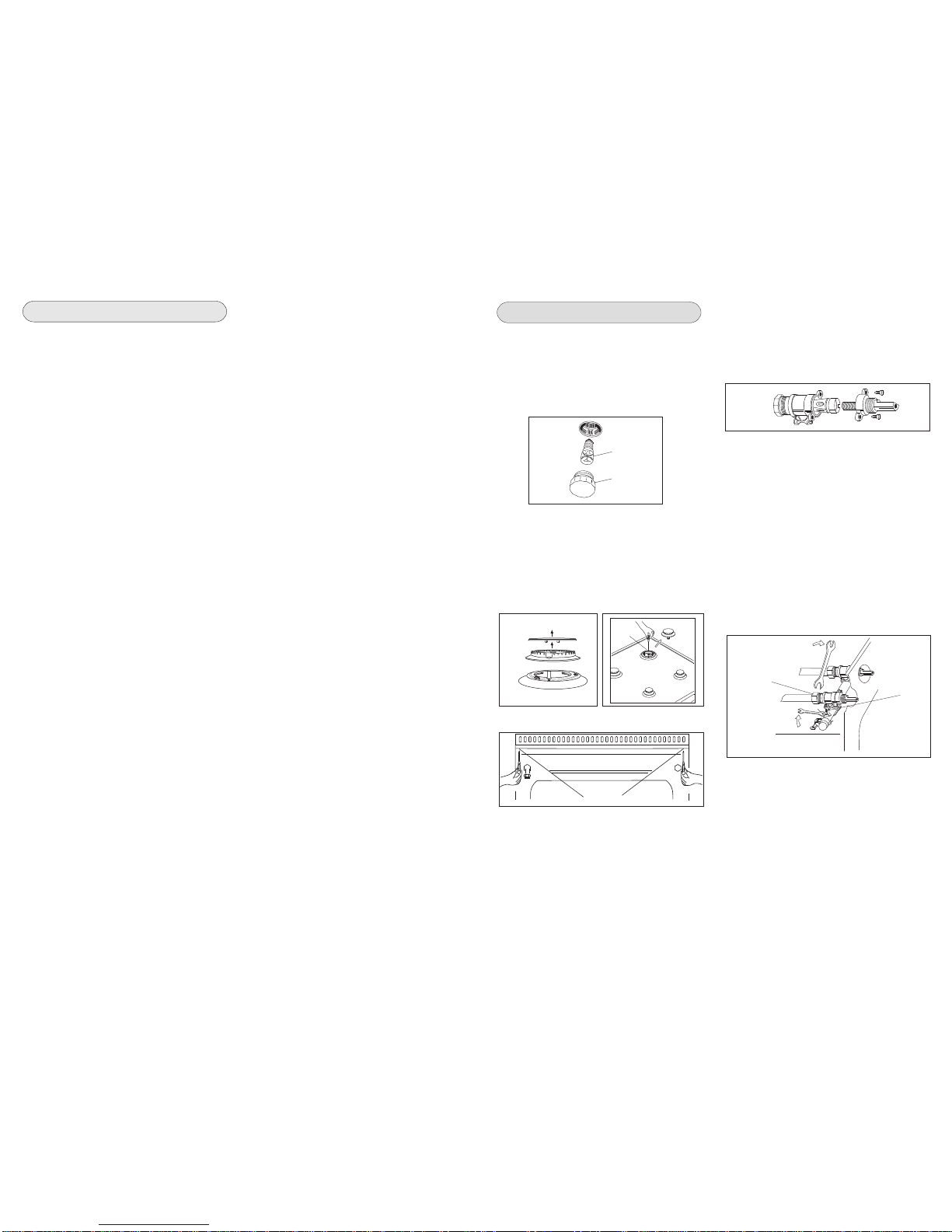
GREASING OF TAPS (all work must be carried out by CORGI
registered engineers)
If a tap becomes stiff to be turned, grease it using a specific high
temperature grease. Proceed as follows: switch the electricity
supply to the appliance off, and chose the gas tap, remove the
hob-top and remove the control panel as described on the previous
paragraph. Unscrew the two fixing screws from the burner body
(see picture) and remove the cone.
Clean the cone and its slot by means of a cloth soaked with a
solvent. Slightly grease the cone with the relevant grease, put it
in its slot, and turn it a few times. Remove the cone again, remo v e
the excess grease making sure the gas entries are not obstructed
by grease. Assemble everything carefully and carry out a gas 2
soundness check on the appliance.
TAPS REPLACEMENT
Isolate the appliance from the electricity supply.
Proceed as follows: chose the gas supply, remove the hob-top
and remove also the control panel as described on the previous
paragraph. Unscrew screw nut D of the gas tube supplying the
burner. Unscrew scre w V fixing the tap to the gas rail and remove
it (see picture).
Note: When replacing the tap it is necessary to replace the seal
gasket, too check the connection carry out a gas soundness
check. (see picture).
A
WARNINGS
Oven lamp (the oven lamp is not covered by the guarantee)
Isolate the cooker from the electricity supply before attempting
to replace the oven lamp.
The oven lamp used has a high temperature specification. To
replace it, proceed as follows: remove the glass co ver (A) (fig. 22)
and replace the lamp with one of the same type. Replace the glass
cover.
Fig. 22
Page 3

10 3
GENERAL INFORMATION
ENVIRONMENT PROTECTION
Packing disposal
Sort packing into different materials (cardboard, polystyrene
etc.) and dispose of them in accordance with local waste
disposal laws.
This appliance complies with the following European Directives:
- 73/23/EEC regarding "Low Voltage".
- 89/336/EEC regarding "Electromagnetic Disturbances".
- 90/396/EEC regarding “Gas appliances”
- 89/109/EEC regarding "Materials in contact with food"
- Moreover the above mentioned Direstives comply with Directive
93/68/EEC regarding CE Marking.
- This household appliance has been designed for cooking and
it must therefore be used for this purpose only.
DEAR CUSTOMER,
• Carefully read these instructions before using the appliance and
keep them for future consultation.
• Keep potentially hazardous packaging (plastic bags, polystyrene
etc.) out of the reach of children.
WARRANTY
Your new appliance is covered by a warranty.
The warranty certificate is inclosed. If it is missing, ask the retailer
for it indicating purchase date, model, and Serial number which
are printed on the data plate identifying the appliance.
Keep the section meant for you, and when of necessary, show it
to the Service engineer together with the purchase receipt.
If you do not follow this procedure, you could be charged for any
service visits that may be necessary.
All “Work” in relation to the Guarantee must be carried out by
Baumatic Ltd or an approved service agent of Baumatic Ltd.
This guarantee applies to UK mainland, Northern Ireland and ROI
(Republic of Ireland) only.
This guarantee is in addition to your statutory legal rights and will
not in any way hinder any legal rights.
The guarantee period starts from the date of the original purchase
and the manufacturer will provide parts and labour required to
repair the appliance should breakdown occur as a result of
mechanical/electrical failure. This service will be given free of
charge within the Guarantee period. For UK mainland and Northern
Ireland only, an additional Insurance scheme is available should
you wish to extend the warranty period.
The guarantee does not cover
* Any damage cause by transit, misuse or neglect.
* Cosmetic and perishable par ts: plugs, fuses, light bulbs, light
covers, cosmetic trims, cables, filters and attachments, knobs,
any rubber and seals, ceramic and glass surfaces, dents,
scratches, paintwork.
* Attachments/Accessories: trivets and handles, griddles, pan
stands, shelves, burner caps and collars, oven liners, plus any
additions hereafter.
* Periodic maintenance, the repair or replacement of parts due
to natural wear and tear.
* Material disclouration, corrosion.
* Incorrect installation, modifications or repair by any unauthorised
personnel.
* Use of non-Baumatic parts.
* damage caused by foreign objects or substances.
* Appliance used for non-domestic use.
* Operation on unsuitable voltage, water or gas supplys.
* Accidents, Civil war, Acts of God or any cause beyond the control
of Baumatic Ltd.
RECCOMANDATIONS AND PRECAUTIONS
GAS ADJUSTMENT
TYPE OF POWER SUPPLY
Different connections can be made simply by moving the jumpers on the
terminal board
* TAKING ACCOUNT OF CONTEMPORANEITY F ACTOR OF 0,59
Cable Type
H05 RR-F
H05 RN-F
ATTENTION:
- Before using the appliance, do not forget to remove the plastic
films protecting some parts of the appliance (facia-panel, parts
in stainless steel, etc.)
- Do not use the appliance as a space heater.
- When the appliance is not in use, we recommend to switch off
the electricity supply to the appliance.
IN CASE OF FIRE:
• In case of fire, close the main valve of the gas supply and
switch off the electricity supply to the appliance and never
pour water onto burning oil. Do not store flammable products or
aerosol containers near the burners, and do not spray them near
lit burners.
FOR YOU AND YOUR CHILDRENS SAFETY
• Do not store items that are attractive to children above or near
the appliance.
• Keep children well away from the appliance: some parts of the
appliance and the pans become very hot during use, and during
the cool down period after use.
• In order to avoid any accidental tipping, pan handles should be
turned towards the back of the cooker, not out into the room or
over adjacent burners.
• When cooking, do not use clothes with large flared sleeves; in
case of accidental contact with a lit burner.
WARNING - OVEN:
When the oven or the grill are in use, accessible parts can
become very hot; it is necessary to keep children well away
from the appliance.
- Never cook food on the base of the oven.
- Keep fingers away from the area of the hinges when closing the
door as it is possible to trap them.
- Do not let children sit down on or play with the oven door. Do not
use the drop down door as a stool to reach above cabinets.
WARNING - GRILL
When using the grill function the oven door must be in the closed
position.
WARMING DRAWER
DO not place inflammable materials or plastic utensils in the
warming drawer (situated below the ovens).
TECHNICAL AFTER SALES SERVICE
Before leaving the factory , this appliance has been tested and set
up by skilled personal, in order to give the best performance
results. Each repair or commissioning that may be necessary
afterwards, must be carried out with a care and attention. For this
reason, we recommend that you always use Baumatic Service
and always specify the nature of the problem and the model of
your appliance.
For UK mainland and Northern Ireland, please contact one of the
above numbers for further information or any other query you
may have.
For ROI (Republic of Ireland), please contact one of the numbers
as below:
Tel: 01 – 4030501 Fax: 014030503
Conversion to Gas (all work must be carried out by CORGI
registered engineers)
Always isolate the cooker from the electricity supply,
- change the injectors,
- adjust the minimum flow of the burners.
REPLACEMENT OF HOB-TOP INJECTORS
In order to change the hob-top injectors, procees as follows: remov e
the panstands, remove burners and flame-spreaders (see fig. A)
unscrew the injector (see fig. B) and replace it with the stipulated
injector for the new type of gas (see table D). Re-assemble all of
the burners, paying attention to place the flame-spreader correctly
on the burner.
A
B
TAB. D GENERAL INJECTORS TABLE
Kind of gas mbar Nozzle Burners Power Watt Consum.
N. Posizione-type max. min. max.
115 -Rapide 3000 750 286 l/h
NATURAL 20 97 -Semi rapide 1750 480 167 l/h
72 -Auxiliary 1000 330 95 l/h
128 -Triple crown 3300 1300 315 l/h
L.P.G. 30 85 -Rapide 3000 750 219 g/h
BUTANE 28 65 -Semi rapide 1750 480 128 g/h
PROPANE 37 50 -Auxiliary 1000 330 73 g/h
93 -Triple crown 3300 1300 241 g/h
MINIMUM FLOW ADJUSTMENT FOR HOB-TOP TAPS
In order to adjust the minimum flame setting proceed as follows:
switch the burner on, and set the knob at the minimum position
. Remove the knob from the tap, place a small b laded screwdriv er
down the centre of the tap shaft (fig. 20).
Attention: on taps with a security valve, the minimum adjusting
screw «Z» is on the body of the gas tap (fig. 21).
Unscrew the adjusting screw in order to increase the flow or screw
it to decrease the flow.
The right adjustment is obtained when the flame has a length of
about 3 or 4 mm.
For butane/propane gas, the adjusting screw must be tight screwed.
Make sure that the flame does not go out passing quickly from
the max. flow to the minimum flow .
Assemble the knob again.
cleaning, but do not let it hang closer than 50mm (2») to the floor.
The cable can be looped if necessary, but make sure that it is not
linked or trapped when the cooker is in position.
Z
Fig. 21Fig. 20
2
1
3
4
5
L
N
A
IMPORTANT
The wires in the mains lead are coloured in accordance with the
following code:
GREEN AND YELLOW.....EARTH
BLUE.................................NEUTRAL
BROWN.............................LIVE
REPLACEMENT OF THE CABLE
In case the cable is damaged, replace it in accordance with the
following instructions:
- disconnect the appliance from the electric network before any
intervention.
- open the box of the supply board as described on the picture
below;
- unscrew screw “A” fixing the cable;
- replace the cable with one of the same lenght and in accordance
with the features described on the table; switch the appliance
off, and close the gas tap
- the ‘green-yellow” earth wire must be connected to the terminal
“ “ and it must be about 10 mm longer thean the live wires;
- the “blue” neutral wire must be connected to the terminal marked
with letter “N”;
- the live wire must be connected to the terminal marked with letter
“L”.
E = GREEN and Yellow / N = BLUE / L = BROWN
400 V 3N~
5
4
3
2
1
L1
L2
L3
N
E
400 V 2N~
5
4
3
2
1
L1
L2
N
E
230
V ~
5
4
3
2
1
L1
N
E
TYPE AND CROSS-SECTION OF POWER SUPPLY CABLES
230V ~
3 x 6 mm2
ø
*
400V 2 N~ 400V 3 N~
4 x 4 mm2 5 x 2,5 mm2
CERAMIC HOB
plates Ø mm Watt
G
H
F
I
L
Page 4

4 9
HOB USE
USING GAS BURNERS
The following symbols are on the control panel next to each knob:
- Black circle gas off
- Large flame maximum setting
- Small flame minimum setting
The minimum setting is at the end of the anticlockwise rotation of
the knob. All operation positions must be selected between the
positions of max. and min., never select them between max. and
off.
MANUAL IGNITION
To ignite the burner, press the knob of the selected burner and
turn it anticlockwise to the minimum position then light with a
match.
ELECTRIC IGNITION (optional)
To ignite the burner, press the knob of the selected burner and
turn it anticlockwise to the minimum position; simultaneously press
the electric ignition button on the control panel marked with symbol
.In the case of a power failure, the burner can be lit using a
match.
AUTOMATIC ELECTRIC IGNITION (optional)
To ignite the burner, press the knob of the selected burner and
turn it anticlockwise to the minimum position. Keeping the knob
pressed in, the automatic ignition of the burner will operate.
In case of power failure, the burner can also be lit using a match.
APPLIANCES WITH SAFETY VALVE (optional)
Follow the same procedure described above to ignite the burners.
In this case, once the burner is lit you have to hold the control
knob pressed in for approximately 10 seconds until the burner
flame stays on, if the flame does not stay on repeat the process.
If for any reason the burner flame goes out, the safety valve
automatically shuts off the gas supply to the burner in question.
ENERGY SAVING TIPS
• The diameter of the pan bottom should correspond to that of
the burner. The burner flame must never extend beyond the
diameter of the pan. Use flat-bottomed pans only.
• Whenever possible, keep a lid on the pan while cooking, this
will save energy.
• Cook vegetables, potatoes, etc. with as little water as possible
to reduce cooking times.
USING ELECTRIC HOTPLATES
When using an electric hotplate for the first time or after a long
period of disuse, turn the knob to 1 and let it heat for about 20
minutes to eliminate any possible moisture absorbed by the internal
insulating material.
- Dry the bottom of the pan before placing it on the hotplate.
- Turn the hotplate on only after placing the pan on it.
The hotplate is controlled by a commutator. Turn the knob until
position 1 to turn the hotlplate on (Fig.1). A warning light on the
control panel will inform you if the plate is on or off.
GUIDELINE TABLE
The actual settings depend on the quantity and quality of the food
and the type of saucepan.
0 Off
1 Very slow
2 Low
3 Medium-
Low
4 Medium
5 High
6 Very high
For melting butter, chocolate, etc.
For heating small amounts of liquid.
For heating larger amounts of liquid.
For preparing slow-cooking creams and sauces.
For thawing frozen foods and cooking stews, cooking
at boiling or lower temperatures.
For boiling foods, roasting delicate meats and fish.
For braising chops and steaks, for large meat soups.
For boiling large amounts of water and frying.
Pos. Heat Use
Intensity
0
1 - 2
3 - 4
5 - 6
7 - 8
9 - 10
11
The plate is controlled by an energy regulator.
1) To activate the first circuit, rotate the knob from 1 to 11 (Fig.3).
2) To activate the second circuit, rotate the knob past the
number 11, then repositioning on the required number.
To return to single-circuit operation, reset the knob to zero then
to the number required.
A warning light on the control panel will inform you if the cooking
area is on or off.
USE OF PLATES WITH DOUBLE CIRCUIT ENERGY
REGULATOR
Fig.1 Fig. 2
ENERGY SAVING TIPS
• The diameter of the saucepan must be the same or slightly larger
than that of the electric hotplate. Never use a pan which is
smaller than the electric hotplate.
• Use flat-bottomed pans only.
• Preferably cover pans with a lid to permit cooking at a lower
heat.
• Always cook vegetables and potatoes, etc. in as little water to
reduce cooking times.
Fig. 4
6
5
4
3
2
1
0
GAS CONNECTION
BURNERS PANS
Ø min. Ø max
RAPIDE 180 mm 220 mm
SEMIRAPIDE 120 mm 200 mm
AUXILIARY 80 mm 160 mm
TRIPLE CROWN 220 mm 260 mm
6
7
8
9
10
11
5
4
3
2
1
6
7
8
9
10
11
5
4
3
2
1
The cooker is fitted with 4 legs for an eventual alignment in height
with the furniture. To assemble them, it is necessary to raise the
cooker and to screw the four legs into the suitable threadings
placed on the corners on the bottom of the appliance.
This appliance must be installed by a competent person in
accordance with the current versions of the following UK (United
Kingdom) or ROI (Republic of Ireland) Regulations and Safety
Standards or their European Norm Replacements.
Irish Standard for Domestic Gas Installations
IMPORTANT
This cooker is supplied for use (see label on the bach near the
inlet connection of the gas) and cannot be used for any other gas
without modification.
Conversion for other gases must only be undertaken by a qualified
person. For information for use on other gases contact your local
Service Centre.
The cooker must be installed by a qualified person in accordance
with the Gas Safety (Installation and Use) (Amendment) Regulations
1990 and the relevant building/I.E.E. Regulations.
Failure to install the appliance correctly could invalidate any
manufacturers warranty and lead to prosecution under the above
quoted regulations.
In the UK, CORGI registered installers are authorised to undertake
the installation and service work in compliance with the above
regulations. All Baumatic engineers are CORGI registered.
Provision for Ventilation
The room containing the cooker should have an air supply in
accordance with BS 5440: Part 2: The room must ha v e an opening
windows or equivalent; some rooms may also require a permanent
vent. If the room has a volume between 5 and 10m 3, it will require
an air vent of 50cm2 effective area unless it has a door which opens
directly to the outside. If the room has a volume of less than 5m3,
it will require an air vent of 100cm2 effective area. If there are other
fuel burning appliances in the same room, BS 5440: Part 2: 1989
should be consulted to determine air vent requirements. Ensure
that the room containing the cooker is well ventilated, keep natural
ventilation holes or install a mechanical ventilation device
(mechanical cooker hood). Prolonged intensive use of the appliance
may call for additional ventilation, for e xample opening of a window,
or more effective ventilation, for example increasing the level of
mechanical ventilation where present. This cooker is not fitted with
a device for discharging the products of combustion. Ensure that
the ventilation rules and regulations are followed. Excess steam
from the oven, vents out at the top back edge of the cooker, so
make sure that the walls behind and near the cooker are resistant
to heat, steam and condensation. Your cooker must stand on a
flat surface so that when it is in position the hob is level. When in
position check that the cooker is level by using a spirit level and
adjust the 2 feet at the rear and the 2 feet at the front if necessary.
It is important that the cooker is stable and level for the overall
cooking performance.
Remember that the quantity of air necessary for combustion must
never be less than 2m3/h for each kW of power (see total power
in kW on the appliance data plate).
Gas Safety (Installation & Use) Regulations
It is the law that all gas appliances are installed by competent
persons in accordance with the current edition of the Installation
& Use Regulations. It is in your interest and that of safety to
ensure compliance with the law.
In the UK, CORGI registered installers work to safe standards of
practice. The cooker must also be installed in accordance with the
current edition of BS 6172. Failure to install the cooker correctly
could invalidate the warranty, liability claims and could lead to
prosecution.
Gas Connection (all installation and service work must be
carried by a CORGI registered engineer)
Prior to installation, ensure that the local distribution conditions
(nature of the gas and gas pressure) and the adjustment conditions
are compatible. The adjustment conditions for this appliance are
stated on the rating plate which can be found on the back cover.
This appliance is not designed to be connected to a combustion
products evacuation device. Particular attention should be given
to the relevant requirements regarding ventilation.
Connection to the cooker should be made with an approved
appliance flexible connection to BS 669. Models for use with LPG
should be fitted with a hose suitable for LPG and capable of
withstanding 50mbar pressure. A length of 0.9 to 1.25m is
recommended. The length of hose chosen should be such that
when the cooker is in situ, the hose does not touch the floor.
The temperature rise of areas at the rear of the cooker that are
likely to come in contact with the flexible hose do not exceed 700C.
Gas pressure may be checked on a semi-rapid hob burner. Remove
the appropriate injector and attach a test nipple. Light the other
burners and observe that the gas pressure complies with the gas
standards in force.
Certain types of cookers can be connected to the supply both on
the right and left hand side at the rear of the cooker. To reverse
the position, remove the blanking plug and refit in the side not to
be used. On completion carry out a gas soundness.
INLETSTOP
ELECTRICAL CONNECTION
This appliance must be installed by a qualified person in
accordance with the latest edition of the IEE Regulations and
in compliance with the manufacturer instructions.
Ensure that the voltage is the same as that stated on the rating
plate.
WARNING! THIS APPLIANCE MUST BE EARTHED
The cooker must be connected to a suitable cooker control unit
incorporating a double pole switch having a contact separation of
at least 3mm in all poles, which is adjacent to (but not above),
and not more than1.25m away from the cooker and easily
accessible. We recommend that the cooker circuit is rated to
20amps.
Cable type H05 RRF 3X 2.5mm
2
Connecting the mains cable
Open the mains terminal block cover as shown, unscrew the cable
clamp «A» and unscrew (not fully) the screws in the mains terminal
block «L N E» which secure the three wires of the mains cable.
Fit the cable and refit the cable clamp «A» .
Allow sufficient cable length for the cooker to be pulled out for
USE OF PLATES WITH ENERGY REGULATOR
The plate is controlled by an energy regulator.
To activate the circuit, rotate the knob from 1 to 11 (Fig.2).
A warning light on the control panel will inform you if the cooking
area is on or off.
Fig.3
Page 5

8 5
The best thickness for pan bottoms is 2-3 mm in case of enamelled steel
and 4-6 mm for stainless steel with sandwich type bottoms.
There is a simple way of checking whether the pan bottom is of the right
shape (when cold).
Rest the middle of the bottom at an angle against the straight edge of a
table and slip a few strips of typing paper between them.
As a guide five to ten pieces of paper is correct for enamelled steel pans
and two to five strips for stainless steel (the higher number applies to the
larger sizes of pan).
These rules are very important. If they are not followed there will
be a great loss of heat and energy, and the heat not absorbed by
the saucepan will spread to the hob, frame and surrounding
cabinet.
Using the cooking hob.
The first few times the hob is used, it may give off acrid, burning
smells. These will disappear completely with repeated use.
Each cooking area has a selector knob on the appliance control
panel for setting different temperature levels.
For normal cooking, place the saucepan on the desired area of
the hob and set the knob to the maximum heat.
A warning light on the control panel will inform you if the cooking
area is on or off.
Some of the cooking work-tops have an indicator light between
the two front cooking areas, which lights up when one or more of
the cooking areas goes above the temperature of 60°C.
The indicator light switches off only when the temperature of the
cooking areas goes below about 60°C.
After a few minutes, when the contents of the saucepan are boiling,
turn the knob to a lower position, depending on the quantity, so
that the saucepan does not splash over and there is no waste of
heat.
Important
Be very careful about the safety of children when using the ceramic
hob.
Attention
Although the hob surface is very tough, it is certainly not unbreakable
and it can be damaged, especially if pointed or hard objects fall
on it with a certain force.
Do not use the hob if the surface is broken or cracked; contact
the assistance service immediately.
CERAMIC WORK-TOP
The work-top is fitted with cooking areas of different diameter and power.
The positions are clearly marked. The heating occurs only within the
diameters marked on the work-top.
For efficient cooking and energy saving, it is essential to use only suitable
saucepans.
Cookware with rough bottoms should not be used since these can scratch
the ceramic surface. Before use, make sure that pan bottoms are clean
and dry.
Pans should have the same diameter as the cooking zone they are used
on.
When cold, pan bottoms should be slightly concave, as they expand when
they are hot and lie flat on the surface of the hob. This transfers the heat
best.
USE OF THE ELECTRIC OVEN
The first time the oven is used, it may give off smells, these are
caused by residues left by the production processes and is quite
normal (it is necessary to heat up the oven at the maximum
temperature for about 30-40 minutes in order to burn off these
residues).
Once this process is complete cooking can commence.
The oven is fitted with: a wire trivet for cooking food contained in
oven dishes or placed directly on the trivet itself, a drip-tray for
cooking sweets, biscuits, pizzas, etc., or for collecting juices and
fats from food cooked directly on the trivet.
Note: The following tables give the main points for cooking some
of the most common dishes. The cooking times recommended in
these tables are approximate. After a few tries, we are sure that
you will be able to adjust the times to get the results you want.
Conventional cooking table TAB. B
Fan oven cooking table TAB. C.
GLASS-CERAMIC SURFACE
To clean the work-top, you must follow the same precautions you
use to clean the glasses of your house. Soft stains caused by
aluminium pans bottoms can be removed by means of vinegar.
Make sure that sugar does not fall on the work-top during cooking,
if it falls disconnect the relevant hotplate, and clean as soon as
possible with hot water, before it gets cold.
In case there are stains of burnt sugar or similars after cooking,
clean them using a spatule or a razor before the cooking zone
becomes cold (see picture 10).
OVERALL DIMENSIONS
min. 20mm
min.100
min. 50 mm min. 50 mm
min. 650 mm
min. 400 mm
min. 20mm
INSTRUCTIONS FOR THE USER
895
935
600
110
875
Location
Your cooker is heavy, so be careful when moving or positioning
it. Do not try to move the cooker by pulling on the doors, handles
or control panel. The cooker is designed to “slot in” between 600mm
deep cabinets, spaced approximately 1000mm apart. It can also
be used free-standing, with a cabinet to one side, in a corner
setting or with its back to a wall. However, it must not be situated
with either side closer than 20mm to a combustible wall or cupboard
that is higher than the cooker. It should not be installed at the end
of a run of cabinets if there is a cabinet at immediate right angles
to the cooker door.
In case of installation between kitchen units, their sides must
withstand a temperature of at least 85 degrees C.
The wall behind the cooker and 450mm above and across the
width of the cooker, should be an incombustible material or easy
clean surface such as ceramic tiles.
Any overhanging surface or cooker hood should be at least 750mm
(30”) above the cooker hob. We do not recommend positioning
the cooker below wall cupboards, as the heat and steam from the
cooker may cause damage to the cupboard and its contents.
The cooker may be located in a kitchen, or a bed-sitting room, but
not in a room containing a bath or shower. The cooker must not
be installed in a bed-sitting room of less than 20m3 .
LPG Models must not be installed in a room or internal space
below ground level, e.g. in a basement.
WARNINGS
The technical data is indicated on the data plate placed inside
the front appliance drawer (E ). The adjustment conditions are
shown on the label stuck on the packaging and on the appliance.
Do not use the oven door handle to move the appliance, such as
removing i from the packaging. The appliance is in class 1 or class
2 subclass 1.
INSTALLATION IMPORTANT:
The adjacent furniture must be able to withstand a minimum
temperature rise of 85deg C during periods of use. If the appliance
is to b installed near units, leave the minimum gaps specified in
the table below.
Dish Temp. °C. Minutes Weight kg.
Firs courses
Lasagne 200-220 20-25 0,5
Oven pasta 200-220 25-30 0,5
Creole rice 200-230 20-25 0,5
Pizza 210-230 30-45 0,5
Meat
Roast veal 160-180 65-90 1-1,2
Roast pork 160-170 70-100 1-1,2
Roast ox 170-190 40-60 1-1,2
Roast beef joint 170-180 65-90 1-1,2
Roast fillet beef (rare) 180-190 40-45 1-1,5
Roast lamb 140-160 100-130 1,5
Roast chicken 180 70-90 1-1,2
Roast duck 170-180 100-160 1,5-2
Roast goose 160-180 120-160 3-3,5
Roast turkey 160-170 160-240 5 approx.
Roast rabbit 160-170 80-100 2 approx.
Roast hare 170-180 30-50 2 approx.
Fish 160-180 acc. to weight
Sweets (pastries)
Fruit flan 180-200 40-50
Plain sandwich cake 160-180 35-45
Sponge sandwich cake 200-220 40-45
Sponge cake 200-230 25-35
Currant cake 230-250 30-40
Buns 170-180 40-60
Strûdel 160 25-35
Cream slices 180-200 20-30
Apple fritters 180-200 18-25
Sponge finger pudding 170-180 30-40
Sponge finder biscuits 150-180 50-60
Toasted sandwiches 230-250 7
Bread 200-220 40
Dish Temp. °C. Minutes
Fish 180-240 acc. to size
Meat
Roast ox 250 30 per kg.
Roast veal 200-220 30 per kg.
Chicken 200-240 50 about
Duck and goose 220 acc. to weight
Leg of mutton 250 30 per kg.
Roast pork 250 60 per kg.
Soufflets 200 60 per kg.
Sweets (pastries)
Tea-cake 160 50-60
Sponge finger 160 30-50
Shortcrust pastry 200 15
Puff pastry 250 15
Fruit flan 200-220 30
Meringues 100 60
Quiches, etc. 220 30
4 quarters 120-140 60
Buns 160-180 45
OVEN
Clean the enamelled parts with a damp sponge using soap and
water. Grease can be easily removed using hot water or a specific
cleansing agent for enamelled surfaces.
Do not use abrasive cleansers.
OVEN DOOR
For some models, the oven door can be disassembled in the
following way:
hinges A are provided, for this purpose, with two movable jumpers
B; these, once hooked to the hinges slots C, when the door is
completely opened, block them. After that lift the door outward
carring out the two movements shown in the picture. To do that,
operate on the door sides next to the hinges. In order to reassemble the door, introduce the hinges in their relevant slots.
Before closing the door, do not forget to remove the movable
jumpers B (Fig.11).
Attention, in proximity of the oven door hinges, there is hurt danger.
ELECTRIC HOTPLATES
After use, for a good conservation, the hotplate must be slighty
greased by means of a cloth soaked with oil, so that the surface
remains always clean and bright.
This avoids the eventual formation of rust too.
Fig. 10
A
B C
Fig. 11
Page 6

6 7
INSTRUCTIONS FOR USE OF CONTROL DEVICE
Setting
To set, press and release the desired function, and within 5 seconds
set the time with + and - buttons.
+ and - buttons.
The + and - buttons increase or decrease the time at a speed
depending on how long the button is pressed.
Setting the time
Press any two buttons (cooking time, end time, minutes counter)
at the same time, and + or - button to set the desired time. This
deletes any previously set programme and the “AUTO” symbol
flashes.
Manual use
By pressing the manual button the “AUTO” symbol switches off
and the saucepan symbol lights up.
Manual operation can only be enabled after the automatic
programme is over or it has been cancelled.
Automatic use
Press the cooking time or end time button to switch automatically
from the manual to the automatic function.
Semi-automatic use with cooking time setting
Press the cooking time button and set the desired time with + or
-. The AUTO and cooking time symbols light up continuously. The
relay switches on immediately. When the cooking end time
corresponds to the time of day, the relay and cooking time symbol
switch off, the sound signal rings and the AUTO symbol flashes.
Semi-automatic use with end time setting
Press the end time button. The time of day appears on the display.
Set the cooking end time with + button. The AUTO and cooking
time symbols light up continuously. The relay contacts switch on.
When the cooking end time corresponds to the time of day, the
relay and the cooking time symbol switch off. When the cooking
time is up, the AUTO symbol flashes, the sound signal rings and
both the relay and the cooking time button switch off.
CARE AND MAINTENANCE
Before cleaning the appliance, disconnect the gas general
tap and unplug the appliance or disconnect power at the
main circuit breaker of the electrical system.
Do not clean the appliance surfaces when still hot.
IMPORTANT
Periodically check the external gas connection hole and
replace it when it shows any sign of deterioration. Do not
attempt to repair the gas hose under any cincumstances.
ENAMELLED SURFACES
Clean with a damp sponge using soap and water.
Grease can be easily removed using hot water or a specific
cleansing agent for enamelled surfaces. Do not use abrasive
cleansers.
Do not leave any acid or alkaline substances (lemon juice, vinegar,
salt, etc.) on the enamel.
Clean the parts in stainless steel with specific cleansers for
stainless steel surfaces.
These detergents must be applied using a soft cloth.
GRIDS AND BURNERS
To clean the work-top burners, remove them by pulling upwards
and soak them for about 10 minutes in hot water with a little
detergent. After having cleaned and washed them, wipe them
carefully.
Make sure that no burner hole is clogged.
Clean the burners once a week or more frequently if necessary.
MAKE SURE YOU HAVE ASSEMBLED THE BURNERS IN A
RIGHT WAY.
CONVECTION MODE (small oven)
The oven is fitted with:
• a lower heating element;
• an upper heating element.
It is possible to select the desired temperature into the oven by
turning clockwise the thermostat knob and depending on the
models, one or more functions:
Oven off
Oven light
60 ÷ max Upper + lower heating element on
Upper heating element on
Lower heating element on
Grill element on
Use of the oven
Note: ovens with separate thermostat and commutator.
When the functions are used, place the thermostat knob
between 180 ÷ 200°C as maximum temperature.
ATTENTION:
The temperature shown on the control panel corresponds to the
temperature in the oven centre only when the functions selected
are or .
Oven lamp
When you turn the control knob to this position, the light will be
on for all the following operations.
Defrosting with fan
The air at ambient temperature is distributed inside the oven for
defrosting food faster.
Natural convection
Both the lower and upper heating elements operate together.
This is the traditional cooking, very good for roasting joints, ideal
for biscuits, baked apples and crisping food.
You obtain very good results when cooking on a shelf adjusting
the temperature between 50 and MAX°C.
Fan oven
Both the fan and the circular heating element operate together.
The hot air is adjustable between and MAX°C and is evenly
distributed inside the oven. This is ideal for cooking several types
of food (meat, fish etc) at the same time without affecting taste
and smell. It is ideal for delicate pastries.
Medium grill
It is ideal for grilling and gratinating small quantities of traditional
food. The thermostat knob must be placed on the maximum position.
Total grill
It is ideal for grilling and gratinating traditional food. Set the
thermostat control knob to the 200°C position.
Fan assisted total grill
The air which is heated by the grill element is circulated by the fan
which distributes the heat on the food. The fan assisted g rill function
can replace the need to use the rotisserie. You can obtain very
good results also with large quantities of poultry, sausage, red
meat. Set the thermostat control knob to the 200°C position.
Air forced lower heating element
The air which is heated by the lower heating element is circulated
by the fan which distributes the heat on the food . This function
can be used between 50° and MAX°C.
Oven selector knob
Depending on the type of oven, it is possible to select one of the
following functions turning the commutator knob clockwise.
MULTIFUNCTIONAL MODE (large oven)
The oven is fitted with:
• a lower heating element;
• an upper heating element;
• a circular heating element surrounding the fan.
N.B.: Always set the temperature on the thermostat knob before
selecting any of the functions.
Oven thermostat knob
To obtain an oven temperature between 50°C and MAX°C, turn the
knob clockwise.
Note:
All the functions mentioned above, switch the oven light on. A warning
light on the control panel will stay lit until the selected temperature is
reached; after it will light up intermittently. Always use the oven with
the oven door closed.
Warning: the appliance must be used always with closed door.
“LED” PROGRAMMER
Features
24 hours clock with automatic programme and minutes counter.
Functions
Cooking time, cooking end time, manual position, clock,
minutes counter, times to be set up to 23 hours 59 minutes.
Display
4-figures, 7-segments diplay for cooking times and time of day.
Cooking time and manual function = saucepan symbol
Automatic function = AUTO
Minutes counter = bell symbol
The symbols light up when the corresponding functions are
selected.
Automatic use with cooking time and end time setting
Press the cooking time button and select the length of the cooking
time with + or - button. The “AUTO” and cooking time symbols
light up continuously. The relay switches on. By pressing the
cooking end time button the next cooking end time appears on
the display. Set the cooking end time with + button. The rela y and
the cooking time symbol switch off.
The symbol lights up again when the time of day corresponds to
the cooking start time. When the cooking time is up, the “AUTO”
symbol flashes, the sound signal rings, the cooking time symbol
and the relay switch off.
Minutes counter
Press the minutes counter button and set the cooking time with
+ or - button.
The bell symbol lights up when the minutes counter is operating.
When the set time is up, the sound signal rings and the bell symbol
switches off.
Sound signal
The sound signal starts at the end of a programme or of the
minutes counter function and it lasts for 15 minutes.
To stop it, push any one of the functions buttons.
Start programme and check
The programme starts 4 seconds after it has been set.
The programme can be checked at any time by pressing the
corresponding button.
Setting error
A setting error is made if the time of day on the clock falls within
the cooking start and end times.
To correct the setting error, change the cooking time or cooking
end time.
The relays switch off when a setting error is made.
Cancelling a setting
To cancel a setting, press the cooking time button and then press
the - button until 00 00 appears on the display.
A set programme will automatically cancel on completion.
Contaminuti
Tempo di cottura
Fine cottura
Manuale
Togliere tempo
Aggiungere tempo
A
U
T
O
50
75
100
125
150
175
200
225
max
60
90
130
170
200
max
 Loading...