

Page 1
INSTRUCTION MANUAL
Page 2

PIANO DI COTTURA DOMINO ELETTROGAS FILOTOP TOUCH
IT
Installazione - Uso - Manutenzione
DOMINO COOKING HOB ELECTROGAS FILOTOP TOUCH
GB
Installation - Use - Maintenance
TABLES DE CUISSON DOMINO ÉLECTROGAZ FILOTOP TOUCH
FR
Installation - Emploi - Entretien
EINBAUKOCHGERÄT DOMINO ELEKTRO FILOTOP TOUCH
DE
Installation - Gebrauch - Wartung
PLACA DE COCCIÓN DOMINO ELECTROGAS FILOTOP TOUCH
ES
Instalación - Uso - Mantenimiento
MESAS DE ENCASTRAR DOMINO ELECTROGÁS FILOTOP TOUCH
PT
Instalação - Uso - Manutenção
Page 3

3
I
Italiano
I
Indice
Istruzioni per l’utente 4
Installazione, 4
Uso, 4
Manutenzione, 7
Istruzioni per l’installatore 8
Installazione, 8
Collegamento gas, 10
Collegamento elettrico, 10
Caratteristiche utilizzatori, 13
QUESTO PRODOTTO È STATO CONCEPITO
PER UN IMPIEGO DI TIPO DOMESTICO.
IL COSTRUTTORE DECLINA OGNI
RESPONSABILITÀ NEL CASO DI EVENTUALI
DANNI A COSE O PERSONE DERIVANTI DA
UNA NON CORRETTA INSTALLAZIONE O DA
USO IMPROPRIO, ERRONEO OD ASSURDO.
L’APPARECCHIO NON DEVE ESSERE
USATO DA PERSONE (COMPRESI BAMBINI)
CON RIDOTTE CAPACITÀ FISICHE,
SENSORIALI O MENTALI, O DA PERSONE
CHE MANCANO DELL’ESPERIENZA E DELLE
CONOSCENZE NECESSARIE SE NON SOTTO
LA SUPERVISIONE O DIETRO ISTRUZIONI
SULL’USO DELL’APPARECCHIO DA PARTE
DI UNA PERSONA RESPONSABILE PER
LA LORO SICUREZZA. I BAMBINI DEVONO
ESSERE CONTROLLATI PER ASSICURARSI
CHE NON GIOCHINO CON L’APPARECCHIO.
Caro Cliente,
sentitamente La ringraziamo e ci
congratuliamo per la scelta da Lei fatta.
Questo nuovo prodotto, accuratamente
progettato e costruito con materiali di
primissima qualità, è stato accuratamente
collaudato per poter soddisfare tutte le
Sue esigenze di una perfetta cottura. La
preghiamo pertanto di leggere e rispettare
le facili istruzioni che Le permetteranno
di raggiungere eccellenti risultati sin dalla
prima utilizzazione. Con questo moderno
apparecchio Le formuliamo i nostri più vivi
auguri.
IL COSTRUTTORE
GB
English
FR
Français
DE
ES
PT
Deutsch
Español
Português
Page 4

4
I
Installazione
Tutte le operazioni relative all’installazione
(allacciamento elettrico, allacciamento gas, adattamento
al tipo di gas, conseguenti regolazioni, ecc.) devono
essere eseguite da personale qualificato secondo le
norme vigenti. Per le istruzioni specifiche vedi la parte
riservata all’installatore.
Uso
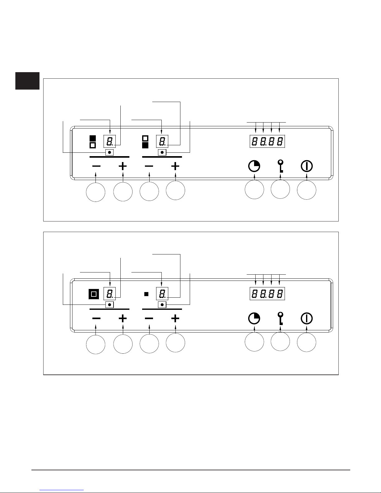
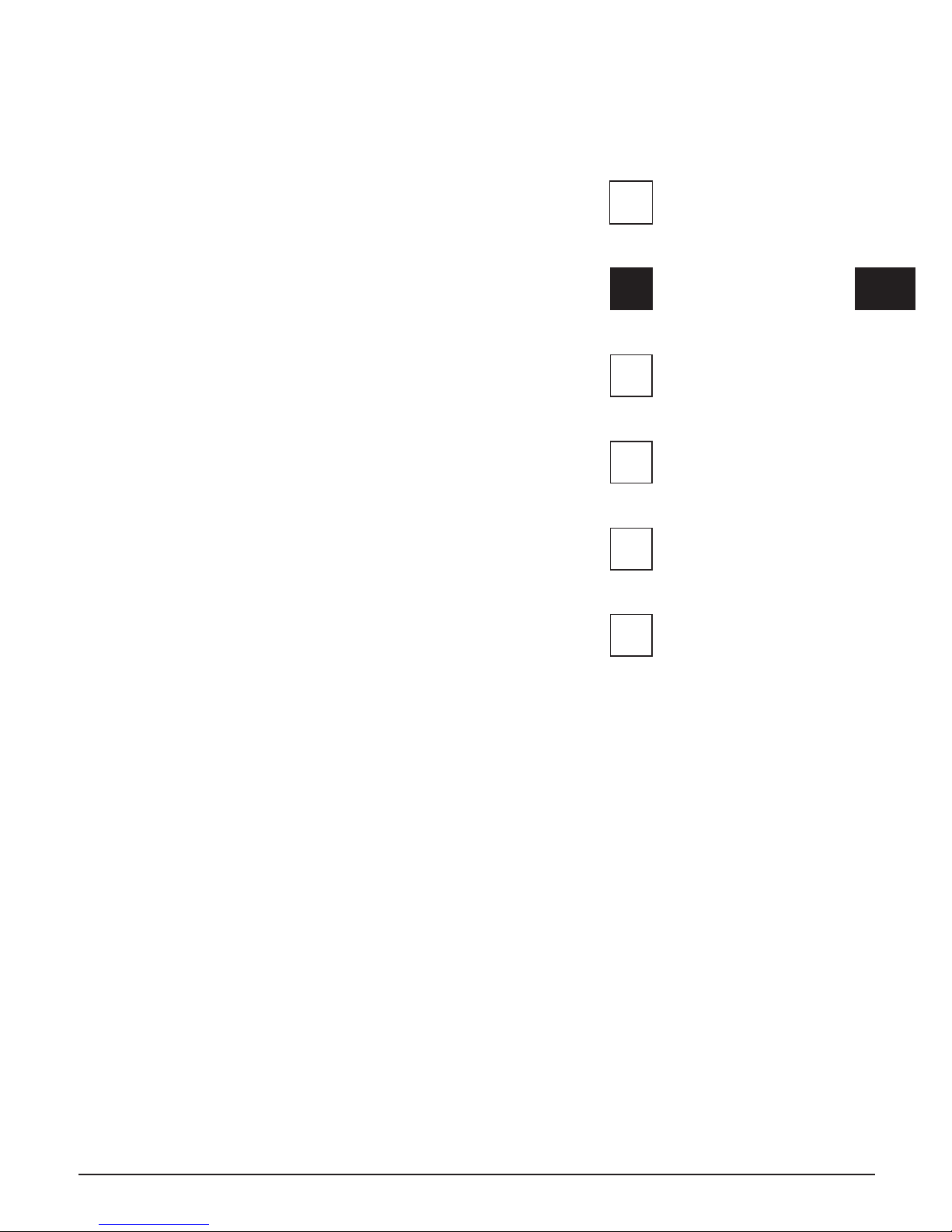
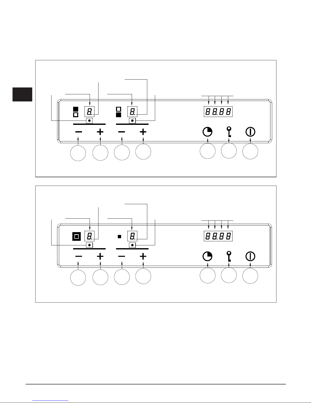
Modalità standby (Fig. 1-2)
Dopo avere alimentato il dispositivo, verrà eseguita una
breve autodiagnosi e una calibrazione della tastiera a
sfioramento (tutti i display e led rimangono accesi per
alcuni secondi). Al termine il display sarà completamente
spento. In questa modalità sarà possibile accendere il
dispositivo soltanto con la pressione del tasto ON/OFF.
Accensione del Piano Cottura
Per accendere il dispositivo è necessario premere in
modo continuo il tasto ON/OFF per almeno 2 secondi.
Il dispositivo si accenderà e i display relativi ai bruciatori
visualizzeranno il livello zero che corrisponde allo stato
di bruciatori spenti.
Accensione di un bruciatore
Per accendere un bruciatore premere i relativi tasti +
e - sul pannello comandi. La pressione dei tasti deve
avvenire in modo simultaneo e continuo per almeno 1
secondo. All’accensione del bruciatore il livello di portata
del bruciatore verrà impostato alla portata media e il
relativo display indicherà il livello 3.
Ogni bruciatore per il quale non è programmato il relativo
temporizzatore, si spegne automaticamente dopo 4 ore
di funzionamento continuo.
L’accensione del bruciatore è segnalata anche dal led
posizionato sotto al relativo display, il quale rimarrà
attivo per tutto il periodo in cui il bruciatore resterà
acceso.
Regolazione del livello fiamma di un bruciatore
A bruciatore acceso, per aumentare il livello di portata
è necessario premere il tasto +, viceversa per diminuire
il livello di portata, è necessario premere il tasto -. Per
ottenere una variazione continua del livello di portata, è
sufficiente mantenere premuto il tasto + o - e rilasciarlo
al livello desiderato. Il livello di portata può variare da
1 a 5.
Spegnimento di un bruciatore
Per ottenere lo spegnimento di un bruciatore è
necessario premere contemporaneamente i rispettivi
tasti + e - per un breve istante.
Spegnimento di tutti i bruciatori
Per ottenere lo spegnimento simultaneo di tutti i
bruciatori è sufficiente premere brevemente il tasto
ON/OFF, in questo modo il dispositivo si porterà in
condizione di standby.
Programmazione del tempo di spegnimento di un
bruciatore
E' possibile impostare in modo indipendente per
ciascuno dei bruciatori, un tempo oltre il quale il
bruciatore si spegne automaticamente.
Per impostare la programmazione del timer di un
bruciatore occorre premere il tasto PT. Sul display di
visualizzazione dell’ora comparirà la scritta Time, a
questo punto premendo il tasto – o + del bruciatore che
si vuole temporizzare, la scritta Time sparirà e comparirà
l’indicazione 0.00. Il bruciatore selezionato è individuato
dall’accensione del relativo Led. La cifra lampeggiante a
sinistra del punto indica le ore, quelle a destra i minuti.
Premendo i tasti + o – del bruciatore selezionato, e’
possibile incrementare o decrementare il numero di ore
di funzionamento da 0 a 9. Mantenendo premuti i tasti
+ o - la variazione del numero di ore avviene in modo
continuo.
Per specificare il numero dei minuti, premere
nuovamente il tasto PT. Si attiva il lampeggio delle cifre
a destra del punto separatore. Per impostare i minuti
agire come indicato per le ore.
Durante la programmazione del tempo e’ possibile
in ogni momento, azzerare l’impostazione corrente
premendo insieme i tasti + e -. Un tempo uguale a
zero disattiva il temporizzatore del bruciatore. Per
confermare il tempo visualizzato sul display occorre
premere il tasto PT. A questo punto rimangono accesi in
modo lampeggiante solo i segnalatori dei bruciatori che
hanno il temporizzatore attivo.
Sul display dell’orologio viene indicato il tempo rimanente
allo spegnimento riportando una ‘t’ davanti alle ore ( ad
es. t0.12 ). Se durante la programmazione non viene
premuto nessun tasto per un periodo superiore a 10
secondi, la procedura di impostazione viene interrotta
in modo automatico e ritornerà la visualizzazione
principale. Eventuali impostazioni in corso di modifica
sul bruciatore selezionato non sono perse e il relativo
timer risulterà attivo.
Il timer può essere programmato sia a bruciatore
spento che a bruciatore acceso, ed il conteggio partirà
immediatamente dopo la conferma del tempo impostato.
Allo scadere del conteggio il bruciatore temporizzato
verrà spento e contemporaneamente verrà emessa una
Istruzioni per l’utente
Page 5
5
I
sequenza di impulsi sonori per una durata di 30 secondi.
Questa sequenza può essere interrotta selezionando il
tasto PT.
Lo spegnimento di un bruciatore da parte dell’utente
determina la disattivazione del relativo timer.
Nota per il modello 2 gas
Qualora venissero programmati entrambi i bruciatori
contemporaneamente, verrà visualizzato sul display
timer il conteggio relativo al bruciatore che si spegnerà
per primo, e questo bruciatore avrà il relativo Led che
lampeggerà ad una frequenza maggiore rispetto all’altro.
Nota per il modello Dual
Per questo modello la programmazione può essere
eseguita solo con i tasti -B e +B. Se saranno accese
entrambe le corone, la temporizzazione sarà valida
per entrambe le corone; se sarà accesa solo la corona
interna, la temporizzazione sarà valida solo per la
corona interna.
Regolazione dell’orologio
In seguito ad interruzioni di alimentazione sarà
necessario impostare l’ora visualizzata dall’orologio
interno al dispositivo. Per regolare l’orologio è
necessario premere contemporaneamente i tasti PT e
KL per almeno 3 secondi.
La cifra lampeggiante a sinistra del punto indica le
ore, quelle a destra i minuti. Premendo i tasti +A o -A
è possibile incrementare o decrementare le ore, e
mantenendo premuti i tasti +A o -A la variazione del
numero di ore avviene in modo continuo.
Per regolare i minuti premere nuovamente il tasto PT.
Si attiverà il lampeggio delle cifre a destra del punto
separatore e poi per variare i minuti agire come indicato
per le ore. Premendo il tasto PT verrà poi memorizzato
l’orario impostato.
Sblocco bruciatore
I bruciatori in stato di blocco hanno il relativo display che
visualizza il carattere “b”. Lo sblocco si attiva premendo
insieme i tasti -A e il tasto KL in modo continuo per
almeno 2 sec. Al termine dello sblocco i bruciatori
verranno ripristinati al livello 0, pronti per essere accesi
nuovamente.
N.B: Se si dovesse ripetere la procedura di sblocco per 5
volte consecutive in un periodo di 15 minuti, il dispositivo
visualizzerà Ft06 e non accetterà alcuna richiesta di
sblocco per ulteriori 15 minuti.
Blocco della tastiera
Si attiva premendo il solo tasto KL per almeno 2 secondi.
Tutti i livelli dei bruciatori rimarranno al livello attuale. Lo
stato di tastiera bloccata si manifesta con l'accensione
dei punti decimali nei display del livello di portata relativi
ad ogni bruciatore. Durante il blocco della tastiera non
è più possibile variare i livelli dei bruciatori o cambiare
le impostazioni del timer, ma è possibile in ogni caso
spegnere il piano premendo il tasto ON/OFF.
Non è possibile sbloccare un bruciatore in blocco mentre
il blocco della tastiera è attivo. Sarà pertanto necessario
sbloccare la tastiera prima di eseguire la procedura di
sblocco bruciatori.
Sblocco della tastiera
La tastiera si sblocca premendo il tasto KL e il tasto +A
per almeno 2 sec. Lo sblocco della tastiera si manifesta
con lo spegnimento dei punti nei display del livello
fiamma.
Calore Residuo
Quando si spegne un fuoco, sul relativo display compare
una "H" per segnalare su quel bruciatore la presenza
di una temperatura ancora elevata, anche il relativo led
vicino al display del timer, rimane acceso.
Il simbolo "H" e il led si spengono successivamente
quando la temperatura del relativo bruciatore si è ridotta.
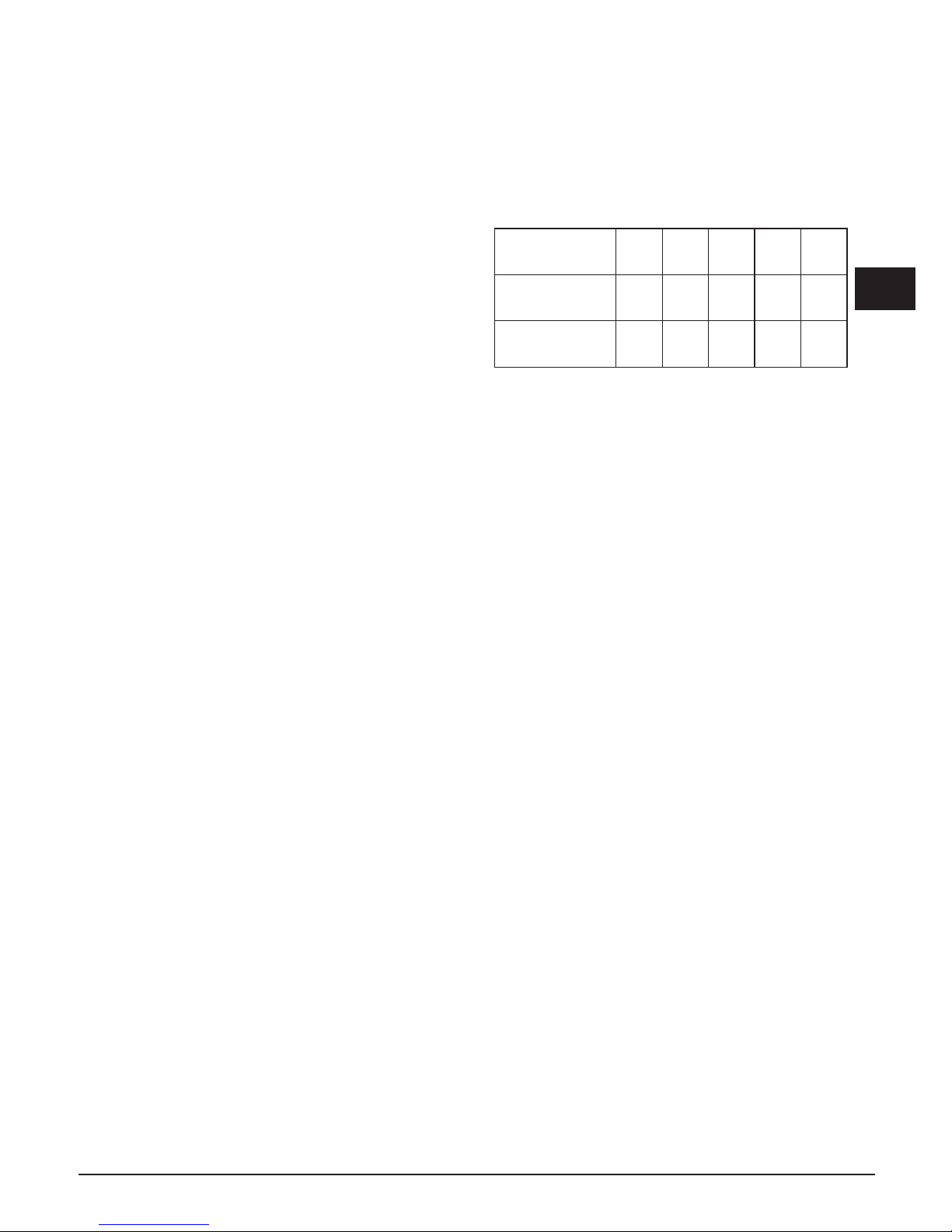
Cotture speciali lente (Duty Cycle)
Questa funzione permette di accendere e spegnere
un bruciatore qualsiasi del piano cottura secondo la
sequenza riportata in tabella.
LIVELLO
IMPOSTATO
1 2 3 4 5
TEMPO DI
SPEGNIMENTO
10
Sec.
20
Sec.
30
Sec.
40
Sec.
50
Sec.
TEMPO DI
ACCENSIONE
50
Sec.
40
Sec.
30
Sec.
20
Sec.
10
Sec.
La funzione si attiva premendo contemporaneamente il
tasto + del fuoco su cui si vuole applicare, ed il tasto
PT (il bruciatore interessato deve essere spento nel
momento in cui si attiva la funzione).
Il bruciatore si accende a livello 3 ed in quel momento
si può impostare, agendo sui tasti + e -, il livello a cui
applicare la funzione.
Se ad esempio si imposta il valore a livello 1, il bruciatore
rimarrà acceso per 50 secondi, poi si spegnerà per 10
secondi e poi ripeterà questo ciclo fintanto che l'utente
non spegnerà il brucitore.
Se l'utente non interviene, dopo 60 minuti si spegne
automaticamente. Quando è attiva questa funzione, il
display del fuoco su cui è attiva, lampeggia.
Page 6
6
I
DISPLAY "A" DISPLAY "B"
PUNTI DECIMALI
DISPLAY TIMER
-A +A -B +B
LED "B"
LED "A"
PT
KL
ON
OFF
DISPLAY "A" DISPLAY "B"
PUNTI DECIMALI
DISPLAY TIMER
-A +A -B +B
LED "B"
LED "A"
PT
KL
ON
OFF
Fig. 1
Fig. 2
Mod: CPH 402 G TC X
Mod: CPH 401 G DWK TC X
Page 7

7
I
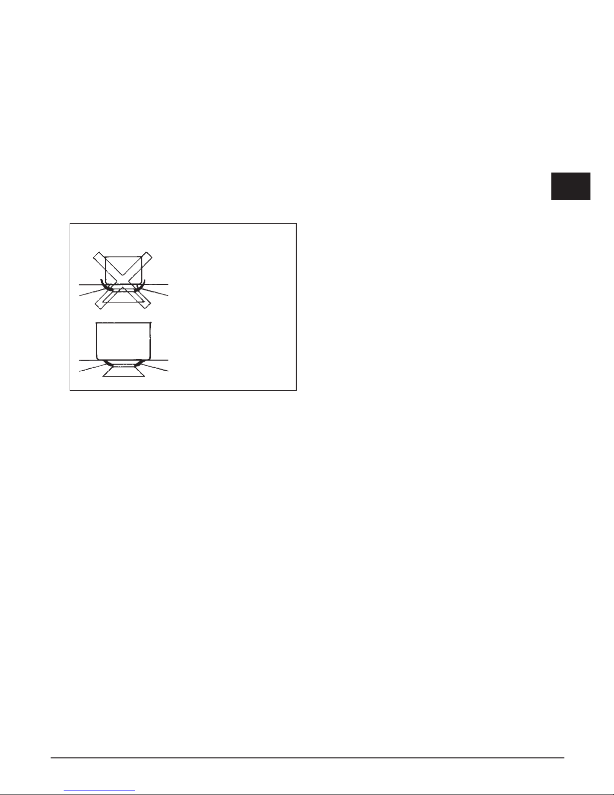
N.B.
- si consiglia di usare pentole di diametro adatto
ai bruciatori evitando che la fiamma al massimo
fuoriesca dal fondo delle stesse (Fig. 3):
- non lasciare pentole vuote sul fuoco acceso.
Al termine della cottura è buona norma provvedere
anche alla chiusura del rubinetto principale del condotto
e/o della bombola.
dual Ø 20-32
rapido Ø 20-24
ausiliario Ø 10-14
GAS
Fig. 3
Manutenzione
Prima di ogni operazione disinserire elettricamente
l’apparecchiatura. Per una maggiore durata
dell’apparecchiatura è indispensabile eseguire
periodicamente un’accurata pulizia generale tenendo
presente quanto segue:
• le partiin vetro e acciaiodevono essere pulite con
prodotti idonei (reperibili in commercio) non abrasivi o
corrosivi. Evitare prodotti a base di cloro (varechina,
ecc.);
• evitaredi lasciare sulpianolavorosostanze acide o
alcaline (aceto, sale, succo di limone, ecc.);
• gli spartiamma ed i coperchietti (parti mobili del
bruciatore) vanno frequentemente lavati con acqua
bollente e detersivo avendo cura di togliere ogni
eventuale incrostazione, asciugati accuratamente,
controllare che nessuno dei fori dello spartifiamma
risulti otturato anche parzialmente.
Controllare periodicamente lo stato di conservazione del
tubo di alimentazione gas. In caso di perdite richiedere
l’immediato intervento del personale qualificato per la
sostituzione.
NON UTILIZZARE PULITORI A VAPORE
Page 8
8
I
Installazione
Questo apparecchio non è provvisto di un dispositivo di
scarico del prodotti della combustione. Si raccomanda
che sia installato in locali sufficientemente areati
secondo le disposizioni di legge vigenti. La quantità
d’aria necessaria alla combustione non deve essere
inferiore a 2.0 m3/h per ogni kW di potenza installato.
Vedi tabella potenze bruciatori.
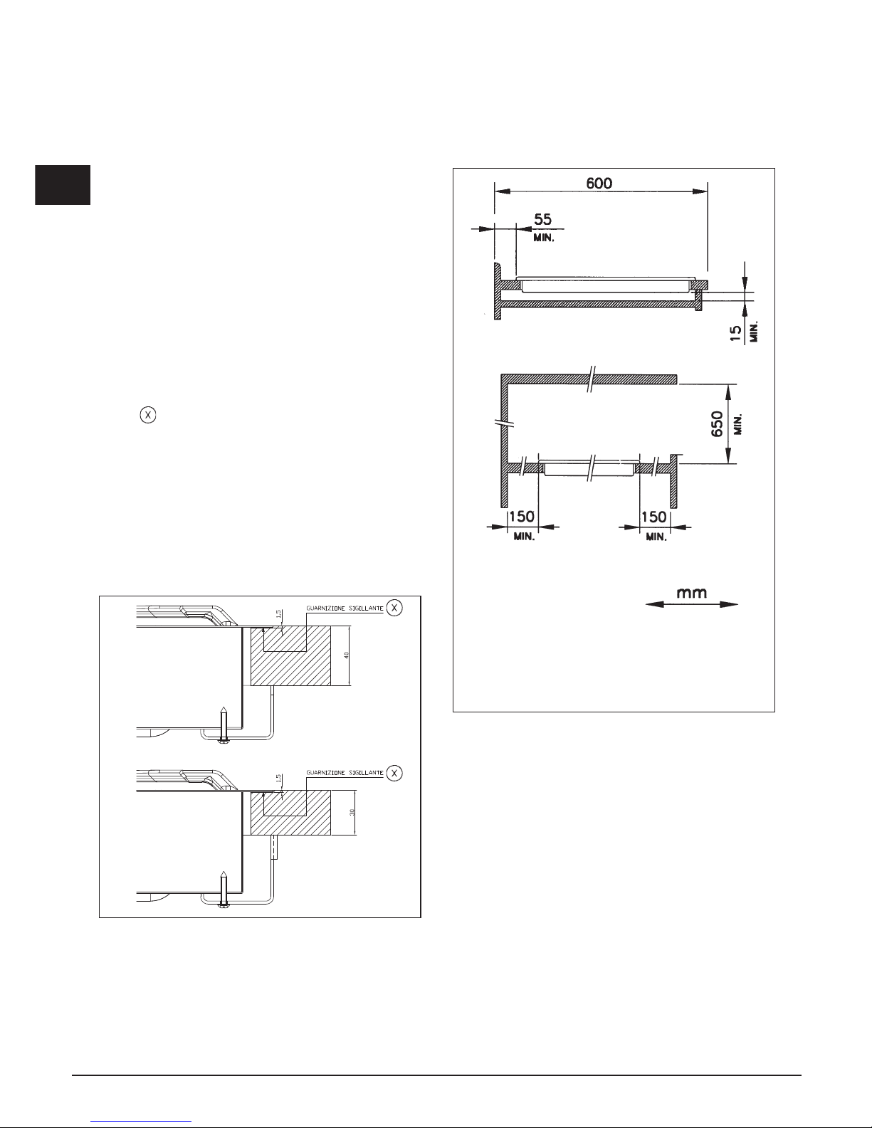
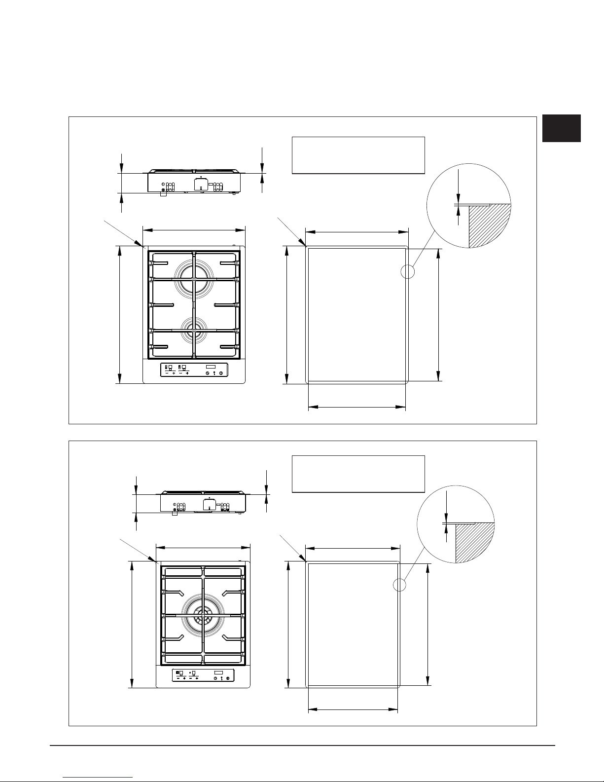
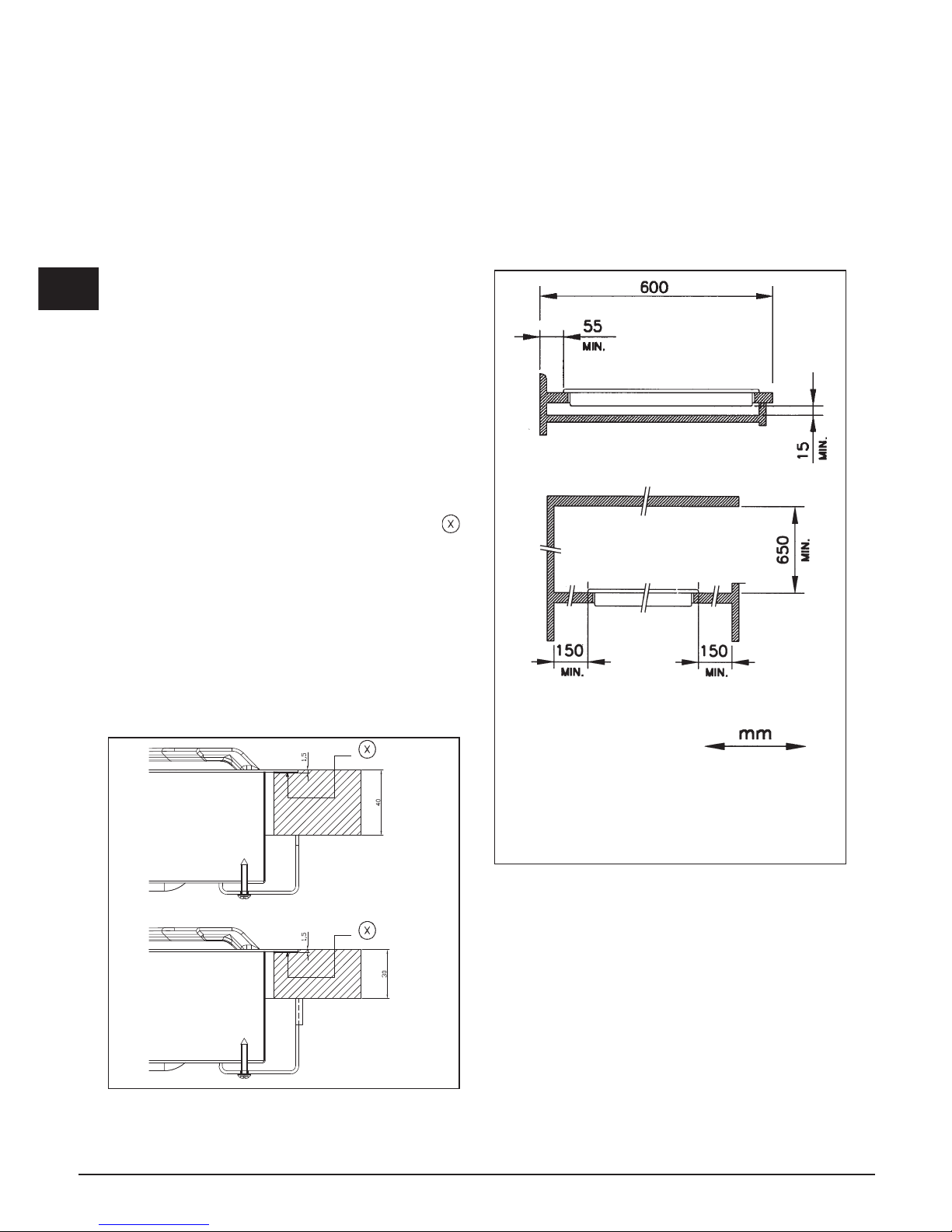
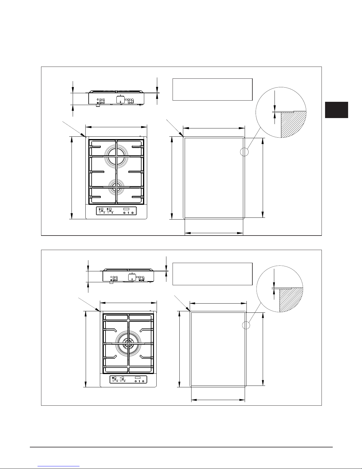
Posizionamento (Fig. 4)
L’apparecchio è previsto per essere incassato in un
piano di lavoro come illustrato nell’apposita figura.
Prima di inserire il piano predisporre la guarnizione di
tenuta su tutto il perimetro della foratura d’incasso.
Le misure d'incasso sono riportate nelle figure 6-7-8-9.
Per i modelli Filotop è necesssario eseguire un
abbassamento nella zona perimetrale del foro di incasso
per una profondità di 1,5 mm.
Per i modelli Semifilotop tale fresatura non deve essere
realizzata.
L'installazione è realizzabile su materiali diversi, quali,
acciaio, marmo, conglomerati, sintetici, legno e legno
rivestito di laminati plastici, purchè resistenti ad una
temperatura di 90°C.
Fig. 4
Sotto il pannello deve essere installato un pannello
di legno o altro materiale isolante, posizionato ad
una distanza minima di 15 mm dall'involucro del
piano.
Istruzioni per l’installatore
Fig. 5
Page 9
9
I
381
+1
0
511
+1
0
360
+1
0
490
+1
0
R
1
2
1.5
510
380
R
1
1
73
1
Fig. 6
1
2
N.B. Per versione Semifilotop
l'abbassamento di 1,5 mm
non è necessario.
1 - AUSILIARIO
2 - RAPIDO
381
+1
0
511
+1
0
360
+1
0
490
+1
0
R
1
2
1.5
380
510
R
1
1
73
1
1
1 - DUAL
N.B. Per versione Semifilotop
l'abbassamento di 1,5 mm
non è necessario.
Fig. 7
Mod: CPH 402 G TC X
Mod: CPH 401 G DWK TC X
Page 10
10
I
Collegamento gas (Fig. 8)
Il collegamento alla bombola o all'impianto deve
essere eseguito da personale qualificato e come
prescritto dalle norme UNI-CIG 7129 e 7131 in vigore e
successivi aggiornamenti accertandosi preventivamente
che l’apparecchiatura sia predisposta al tipo di gas
disponibile. In caso contrario vedi: “Adattamento a
diverso tipo di gas”. Verificare inoltre che la pressione
di alimentazione rientri nei valori riportati nella tabella:
“Caratteristiche utilizzatori”.
Fig. 8
Allacciamento metallico rigido/semirigido
Eseguire l’allacciamento con raccordi e tubi metallici
(anche flessibili) in modo da non provocare sollecitazioni
agli organi interni all’apparecchio.
N.B. - Ad installazione ultimata controllare, con una
soluzione saponosa, la perfetta tenuta di tutto il sistema
di collegamento.
Nota importante: eseguire l'allacciamento
esclusivamente con raccordi e tubi metallici (tubo
flessibile di acciaio a parete continua oppure con tubo
rigido di rame o acciaio) ed in modo che possano essere
ispezionati su tutta la lunghezza.
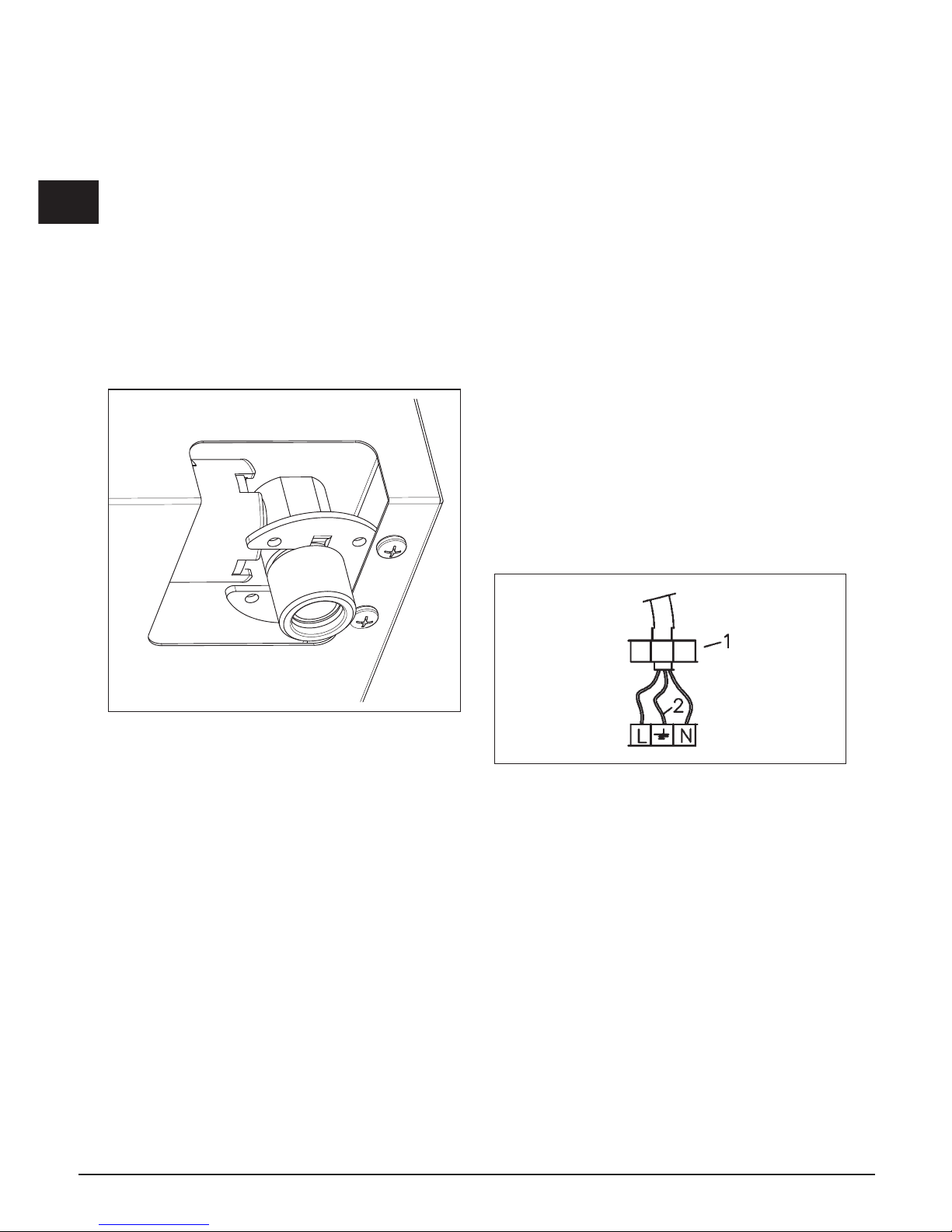
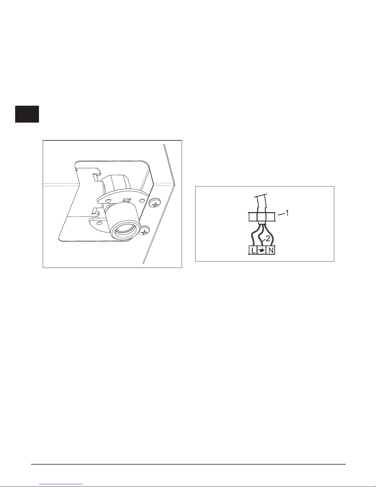
Collegamento elettrico (Fig. 9)
L'installatore deve essere qualificato ed è responsabile
del corretto collegamento elettrico e dell'osservanza
delle norme di sicurezza.
Prima di effettuare l’allacciamento elettrico accertarsi
che:
• lecaratteristichedell’impiantosianotalidasoddisfare
quanto indicato sulla targa matricola applicata sul
fondo del piano;
• l’impianto sia munito di un efcace collegamento di
terra secondo le norme e le disposizioni di legge in
vigore. La messa a terra è obbligatoria a termini di
legge.
Nel caso che l’apparecchiatura non sia munita di
cavo e/o di relativa spina utilizzare materiale idoneo
per l’assorbimento indicato in targa matricola e per la
temperatura di lavoro. Il cavo in nessun punto dovrà
raggiungere una temperatura superiore di 50 °C a quella
ambiente.
Per il collegamento diretto alla rete è necessario
interporre un interruttore omnipolare dimensionato per
il carico di targa che assicuri la sconnessione della
rete con una distanza di apertura dei contatti che
consenta la disconnessione completa nelle condizioni
della categoria di sovratensione III, conformemente
alle regole di installazione (il cavo di terra giallo/verde
non deve essere interrotto). La presa o l’interruttore
omnipolare devono essere facilmente reggiungibili con
l’apparecchiatura installata.
Fig. 9
Page 11
11
I
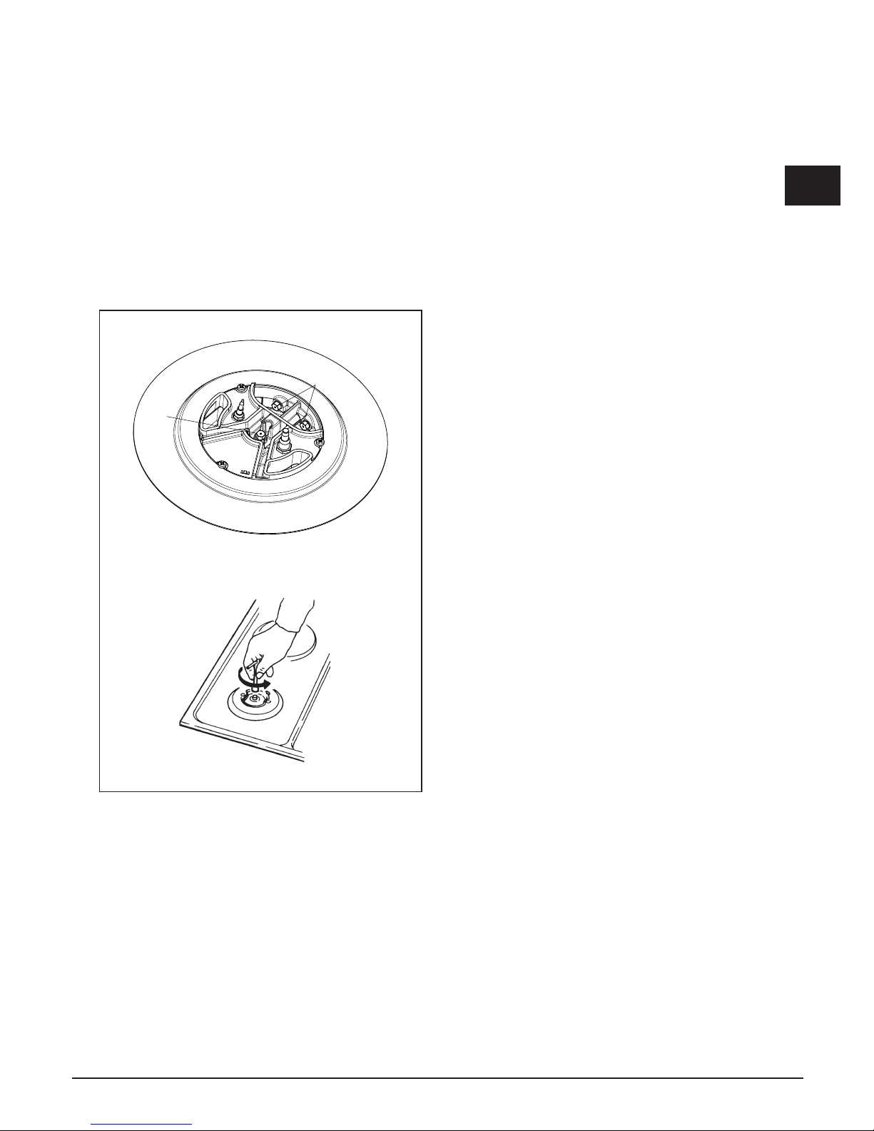
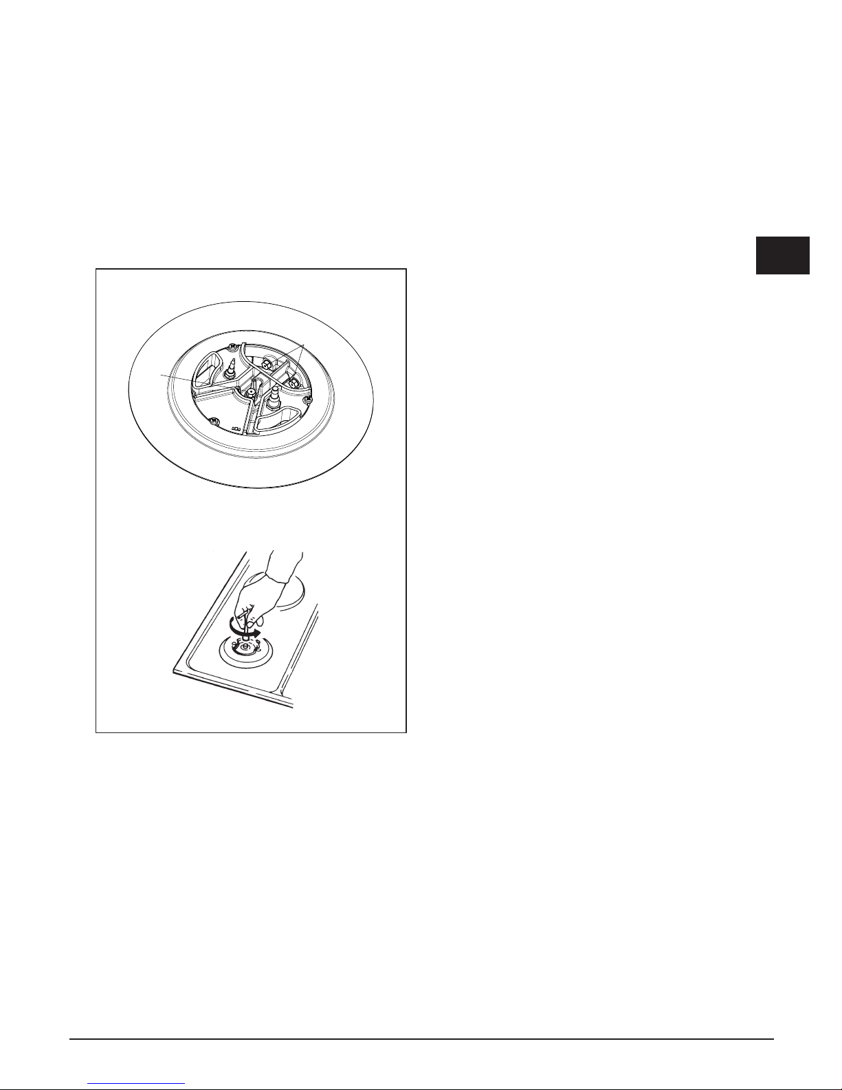
Adattamento a diverso tipo di gas (Fig. 10)
Se l'apparecchiatura risulta predisposta per un diverso
tipo di gas da quello di alimentazione disponibile, si deve
procedere:
• alla sostituzione degli iniettori (g. 10) con i
corrispondenti al tipo di gas da utilizzare (vedi tabella
Caratteristiche utilizzatori);
A
B
Mod. Dual
Fig. 10
Procedura di regolazione della portata minima dei
bruciatori
La procedura per l’acquisizione dei minimi permette
all’operatore la modifica della portata minima predefinita,
adattando ogni bruciatore alle caratteristiche della rete di
distribuzione gas alla quale il piano cottura è allacciato.
La procedura si attiva premendo i tasti +A e –A insieme
al tasto +B in modo continuo per 3 sec, con i bruciatori
tutti spenti.
L’attivazione della procedura di regolazione è segnalata
sul display con la scritta “MIN”. A questo punto è
possibile selezionare il bruciatore da regolare agendo
sui rispettivi tasti + e -. Dopo la pressione di uno dei
tasti, il bruciatore selezionato si accenderà al minimo e
sarà possibile aumentare o diminuire la portata al livello
minimo agendo sui tasti + e – relativi al bruciatore stesso.
Durante la procedura di regolazione i display di livello
fiamma riporteranno l’indicazione - se il minimo impostato
corrisponde con l’impostazione di fabbrica, e l’indicazione
cambierà in ^ o v in modo lampeggiante indicando
rispettivamente una portata superiore o inferiore rispetto a
quella predefinita. La procedura termina premendo il tasto
PT. I livelli di portata minima vengono quindi acquisiti e
memorizzati dal dispositivo, e verranno utilizzati nel
normale impiego del piano cottura.
Selezione del tipo di gas combustibile
E’ possibile configurare il piano di cottura per il
funzionamento con diversi gas (vedi tabella 1). Per
attivare la procedura di selezione del gas combustibile
impiegato è necessario avere il piano in funzione e con
tutti i bruciatori spenti. E’ sufficiente premere assieme
i tasti - del bruciatore A, - del bruciatore B ed il tasto
P- per almeno 2 secondi. L’inizio della procedura di
selezione del tipo di gas combustibile si manifesta con
lo spegnimento dei display di livello dei bruciatori e con
la comparsa sui display del timer della scritta “2020”,
“3029”, “2525” o “2010”, a seconda della configurazione
attualmente in uso. E’ possibile scegliere l’impostazione
desiderata utilizzando i tasti A+ e A-. Per terminare la
procedura l’operatore deve premere il tasto PT.
L’attivazione di questa funzione comporta la
cancellazione di eventuali tempi di spegnimento
programmati per i bruciatori.
Autodiagnosi elettronica
Le schede elettroniche eseguono un controllo continuo
del proprio stato. Qualora si verificassero eventuali
problemi hardware o guasti all’interno della scheda in
grado di pregiudicare la sicurezza dell’utente finale,
il dispositivo si porta in uno stato “sicuro” nel quale le
elettrovalvole vengono spente e sui display comparirà
una codifica relativa al tipo di guasto.
Mod. 2G
Page 12

12
I
Errore
visualizzato
Tipo anomalia Possibile causa Possibile soluzione
B Singolo bruciatore in blocco
Manca il gas
Ripristinare il gas ed effettuare
l’operazione di sblocco dei
bruciatori
Elettrodo di ionizzazione sporco o non investito dalla
fiamma
Pulire o riposizionare l’elettrodo ed
effettuare l’operazione di sblocco
dei bruciatori
Mancata connessione a terra del dispositivo
Controllare i cablaggi ed effettuare
l’operazione di sblocco dei
bruciatori
F
Fiamma parassita / anomalia
circuito rilevazione fiamma sul
singolo bruciatore
Errato cablaggio elettrodi di ionizzazione Controllare i cablaggi
Guasto al circuito Sostituire il dispositivo
Ft00
Anomalia circuito controllo valvola
principale
Guasto al circuito Sostituire il dispositivo
Ft01
Anomalia circuito tensione di
riferimento
Guasto al circuito Sostituire il dispositivo
Ft02 Anomalia circuito watchdog Guasto al circuito Sostituire il dispositivo
Ft03 Anomalia porte microcontrollore Guasto al circuito Sostituire il dispositivo
Ft04 Anomalia Eeprom Guasto al circuito Sostituire il dispositivo
Ft05
Anomalia circuito pilotaggio
valvole
Guasto al circuito Sostituire il dispositivo
Ft06
Superamento del limite massimo
di 5 sblocchi in 15 minuti
E’ stata effettuata l’operazione di sblocco dei bruciatori
più di 5 volte in 15 minuti
Attendere 15 minuti e poi effettuare
l’operazione di sblocco dei
bruciatori
Ft08
Anomalia nel circuito di
alimentazione
Guasto al circuito Sostituire il dispositivo
Ft09
Anomalia generica
E’ stata tolta tensione al dispositivo quando
precedentemente si è verificato un altro tipo di guasto
Effettuare l’operazione di sblocco
dei bruciatori
Anomalia risonatore Guasto al circuito Sostituire il dispositivo
Flt0A
Tutti i bruciatori nello stato di
blocco
Manca il gas
Ripristinare il gas ed effettuare
l’operazione di sblocco dei
bruciatori
Elettrodi di ionizzazione sporchi o non investiti dalla
fiamma
Pulire o riposizionare gli elettrodi ed
effettuare l’operazione di sblocco
dei bruciatori
Mancata connessione a terra del dispositivo
Controllare i cablaggi ed effettuare
l’operazione di sblocco dei
bruciatori
Perdita di gas da una valvola che ha procurato
l’accensione indesiderata di un secondo bruciatore
durante l’accensione del primo.
La presenza di fiamma nel secondo bruciatore per più
di 10 secondi causa questo tipo di anomalia.
Sostituire la valvola difettosa
Flt0[
Errori di comunicazione nella
logica di controllo
Guasto al circuito Sostituire il dispositivo
Flt0E Errore nel controllo della tastiera
Una deformazione meccanica potrebbe avere
compromesso l’appoggio della tastiera al vetro
Attendere per alcuni secondi la
ricalibrazione della tastiera, se
l’errore persiste togliere e ridare
tensione e se l’errore è ancora
presente sostituire il dispositivo
Ft1E Errore hardware tastiera Guasto al circuito
Controllare la scheda tastiera
se inserita correttamente nel
connettore. Sostituire il dispositivo
Ft2E Errore hardware tastiera Guasto al circuito
Controllare la scheda tastiera
se inserita correttamente nel
connettore. Sostituire il dispositivo
Page 13
13
I
CARATTERISTICHE UTILIZZATORI
BRUCIATORI GAS
ALIMENTAZIONE
TIPO PRESSIONE mbar
NORM.
BRUCIATORE
Ø INIETTORE
1/100
PORTATA
TERMICA
NOMINALE
CONSUMO
Gas naturale G20 20
rapido 129 3000 286
l/h
ausiliario 77 1000 95
dual 71A-95B 4000 381
Gas liquido G30/G31 28-30/37
rapido 87 3000 218
g/h
ausiliario 50 1000 73
dual 46A-65B 4000 291
Gas naturale G25 25
rapido 132 3000 332
l/h
ausiliario 80 1000 111
dual 71A-100B 4000 443
G20 10
rapido 155 3000 286
l/h
ausiliario 92 1000 95
dual 80A-143B 4000 381
SERVIZIO ASSISTENZA TECNICA: 0331-723318
Page 14

14
Page 15
15
GB
Index
Instructionsfor use 16
Installation 16
Use 16
Maintenance 19
Instructions for the installater 20
Installation 20
Gas connection 22
Electrical connection 22
User characteristics 25
THIS APPLIANCE IS CONCEIVED FOR
DOMESTIC USE ONLY.
THE MANUFACTURER SHALL NOT IN
ANY WAY BE HELD RESPONSIBLE FOR
WHATEVER INJURIES OR DAMAGES ARE
CAUSED BY INCORRECT INSTALLATION OR
BY UNSUITABLE, WRONG OR ABSURD USE.
THIS APPLIANCE IS NOT INTENDED FOR
USE BY PERSONS (INCLUDING CHILDREN)
WITH REDUCED PHYSICAL, SENSORY
OR MENTAL CAPABILITIES, OR LACK OF
EXPERIENCE AND KNOWLEDGE, UNLESS
THEY HAVE BEEN GIVEN SUPERVISION OR
INSTRUCTION CONCERNING USE OF THE
APPLIANCE BY A PERSON RESPONSIBLE
FOR THEIR SAFETY.
CHILDREN SHOULD BE SUPERVISED TO
ENSURE THAT THEY DO NOT PLAY WITH THE
APPLIANCE.
Dear customer,
We thank you and congratulate you on your
choice.
This new carefully designed product,
manufactured with the highest quality
materials, has been carefully tested to
satisfy all your cooking demands.
We would therefore request you to read
and follow these easy instructions which will
allow you to obtain excellent results right
from the start.
May we wish you all the very best with your
modern appliance!
THE MANUFACTURER
Italiano
I
GB
English
FR
Français
DE
ES
Deutsch
Español
PT
Português
Page 16

16
GB
Installation
All the operations concerned with the installation
(electrical and gas connections, adaptation to type of
gas, necessary adjustments, etc.) must be carried out
by qualified technicians, in terms with the standards
in force. For specific instructions, kindly read the part
reserved for the installation technician.
Use
Standby mode (Fig. 1-2)
When the device is turned on, it performs a brief self-test
and calibrates the touch-pad (all displays and LEDs turn
on for several seconds). At the end, the display will be
completely off. In this mode, the device can be turned on
by simply pressing the ON/OFF key.
Turning on the Cooking Surface
To turn on the device, you must hold down the ON/
OFF key for at least 2 seconds. The device will turn on
and the burner displays will display level zero, which
corresponds to burner off.
Turning on a burner
To turn on a burner, press the relative + and - keys on the
control panel. The keys must be pressed simultaneously
and held down for at least 1 second. When the burner
turns on, the burner will be set to the average flow and
the relative display will show level 3.
Each burner whose timer has not been programmed
will automatically turn off after 4 hours of continuous
operation.
The ignition of the burner is also indicated by the led
under the relative display, which remains active the
whole time the burner is lit.
Adjusting the flame level of a burner
To increase the flow to a burner that is on, press the
+ key and to decrease the flow, press the - key. For a
continuous change in the flow level, just hold down the +
or - key and release it at the desired level. The flow level
varies form 1 to 5.
Turning off a burner
To turn a burner off, press the + and - keys simultaneously
for a brief instant.
Turning off all the burners
To turn all the burners off at the same time, briefly press
the ON/OFF key; this puts the device in standby mode.
Programming the burner switch-off time
It is possible to independently programme each burner
to switch off automatically after a specific length of time.
To programme the timer of a burner, press the PT key.
The word Time will appear on the time display. Now
press the + or – key of the burner to be timed. The word
Time will disappear and be replaced by the indication
0.00. The burner selected is identified by the relative
Led. The flashing digit to the left of the dot indicates
the hours, while those to the right indicate the minutes.
By pressing the + or – keys of the burner selected it is
possible to increase or decrease the operating hours
from 0 to 9. Keeping the + or – keys pressed the change
in the number of hours will take place continuously.
To specify the number of minutes, press the PT key
again. The digits to the right of the dot will start flashing.
Set the minutes in the same way as indicated for the
hours.
When programming the time it is possible to zero the
current setting at any time by pressing the + and - keys.
A time equal to zero deactivates the burner timer. To
confirm the time shown on the display, press the PT
button. At this point, only the indicators of the burners
with the timer active continue to flash.
The time remaining until switch-off is indicated on the
display, with a “t” in front of the time (e.g.: t0.12). If
no button is pressed for more than 10 seconds during
programming, the programming procedure is interrupted
automatically and the main display returns. Any settings
being changed on the burner selected will not be lost
and the relative time is active.
The timer can be programmed both with the burner
switched off or lit, and the counter will start immediately
after the time programmed has been confirmed. When
the countdown ends, the timed burner will turn off and
a sequence of beeps will sound for 30 seconds. This
sequence can be interrupted by pressing the PT key.
If the user switches off a burner, the relative timer is
deactivated.
Note for gas model 2
If both burners are programmed at the same time, the
timer display will show the count for the burner that will
switch off first and the Led related to this burner will flash
faster than the other one.
Note for the Dual model
This model can only be programmed with keys –B and
+B. If both rings are lit, the timer will e valid for both.
If only the inner ring is lit the timer will be valid for the
inner ring only.
Regulating the clock
Following
interruptions to the power supply, it is
necessary to set the time displayed by the clock inside
the hob on the device. To regulate the clock
Instructions for use
Page 17
17
GB
it is necessary to press the PT and KL keys at the same
time, for at least 3 seconds.
The flashing digit to the left of the dot indicates the hours,
while those to the right indicate the minutes. It is possible
to increase or decrease the hours using keys +A or -A
and by keeping keys +A or -A pressed the change in the
number of hours takes place continuously.
To regulate the minutes, press the PT key again. The
digits to the right of the dot will start flashing. Now change
the minutes in the same way as indicated for the hours.
Press the PT key to memorise the time programmed.
Releasing the burner
When a burner is locked the relative display shows the
letter "B". The burner is released by pressing the –A
and KL keys together constantly for at least 2 seconds.
When released, the burners are reset to level 0, ready
to be lit again.
N.B: If the release procedure is repeated 5 times in a row
during a 15 minute time span, the device will indicate
Ft06 and will accept no further request for release for
another 15 minutes.
Locking the control panel
This is activated by pressing the KL key for at least 2
seconds. All burner levels will remain stable. The control
panel locked status occurs when the decimal points on
the display of the capacity level related to each burner
light up. While the control panel is locked it is no longer
possible to change the levels of the burners or change
the timer settings, but it is possible to switch off the hob
by pressing the ON/OFF button.
It is not possible to release a locked burner when the
control panel lock is active. It will be therefore necessary
to release the control panel before activating the burner
release procedure.
Releasing the control panel
The control panel is released by pressing the KL and +A
keys for at least 2 seconds. The control panel is released
when the flame level points on the display go out.
Residual Heat
When a burner goes out, the relative display shows an
"H" to indicate that the temperature of that burner is still
high and the relative LED near the timer display remains
on.
The "H" symbol and the LED turn off when the
temperature of the relative burner is cool.
Special slow cooking (Duty cycle)
This function turns any cook top burner on and off is the
sequence shown in the table.
LEVEL SET. 1 2 3 4 5
TURN-OFF TIME
10
Sec.
20
Sec.
30
Sec.
40
Sec.
50
Sec.
TURN-ON TIME
50
Sec.
40
Sec.
30
Sec.
20
Sec.
10
Sec.
The function is activated by pressing the + key of the
burner you want to apply it to, and the PT key (the burner
involved must be off when this function is activated).
The burner turns on at level 3 and, at that time, you can
set the level to apply the function to by pressing the +
and - keys.
If, for example, you set the value to level 1, the burner
will remain on for 50 seconds, then it will turn off for 10
seconds and repeat this cycle until you turn the burner
off.
If the user does not intervene, the hob switches off
automatically after 60 minutes. When this function is
active, the display of the burner on which it is active
flashes.
Page 18
18
GB
DISPLAY "A" DISPLAY "B"
PUNTI DECIMALI
DISPLAY TIMER
-A +A -B +B
LED "B"
LED "A"
PT
KL
ON
OFF
DISPLAY "A" DISPLAY "B"
PUNTI DECIMALI
DISPLAY TIMER
-A +A -B +B
LED "B"
LED "A"
PT
KL
ON
OFF
Fig. 1
Fig. 2
Mod: CPH 402 G TC X
Mod: CPH 401 G DWK TC X
DECIMAL POINTS
DECIMAL POINTS
Page 19
19
GB
N.B
- We recommend the use of pots and pans with a
diameter matching that of the burner, thus preventing
the flame from escaping from the bottom part and
surrounding the pot (Fig. 3);
- do not leave any empty pots or pans on the fire;
When cooking is finished, it is also a good norm to close
the main gas pipe tap and/or cylinder.
dual Ø 20-32
fast Ø 20-24
auxiliary* Ø 10-14
GAS
Fig. 3
Maintenance
Prior to any operation, disconnect the appliance from
the electrical system. For long-life to the equipment, a
general cleaning operation must take place periodically,
bearing in mind the following:
• the glass and steel parts must be cleaned with
suitable non-abrasive or corrosive products (found
on the market). Avoid chlorine-base products (bleach,
etc.);
• avoid leaving acid or alkaline substances on the
working area (vinegar, salt, lemonjuice, etc.);
• thewall bafe andthesmall covers (mobile parts of
the burner) must be washed frequently with boiling
water and detergent, taking care to remove every
possible encrustation. Dry carefully and check that
none of the burner holes is fully or partially clogged;
c
heck periodically the state of conservation of the
flexible gas feed pipe. In case of leakage, call
immediately the qualified technicians for its
replacement.
DO NOT USE STEAM CLEANERS
Page 20
20
GB
Instructions for the installer
Installation
This appliance
is not provided with a combustion
product discharge. It is recommended that it be installed
in sufficient aerated places, in terms of the laws in force.
The quantity of air which is necessary for combustion
must not be below 2.0 m3/h for each kW of installed
power. See table of burner power.
Positioning (Fig. 4)
The cook top is designed to be built in to a work surface
as shown in the
figure.
Before installing the cook top, install the gasket seal
around the entire perimeter of the hole where it will be
inserted.
The dimensions of the hole are shown in figures 6-7-8-9.
For flush mounting, the perimeter of the hole must be
lowered by a depth of 1.5 mm.
The hole does not need to be milled for Semifilotop
models.
The cook top can be installed on different materials such
as brickwork, steel, marble, conglomerates, synthetics,
wood and wood covered with plastic laminates, so long
as resistant to a temperature of 90 °C.
Fig. 4
A panel made of wood or other insulating material
must be installed under the cook top at a distance
of at least 15 mm from the surface.
SEAL
SEAL
Fig. 5
Page 21
21
GB
Fig. 6
381
+1
0
511
+1
0
360
+1
0
490
+1
0
R
1
2
1.5
510
380
R
1
1
73
1
1
2
Diagram below shows both
flush and proud mounting cut
out dimensions.
1 - AUXILIARY
2 - RAPID
381
+1
0
511
+1
0
360
+1
0
490
+1
0
R
1
2
1.5
380
510
R
1
1
73
1
1
1 - DUAL
Diagram below shows both
flush and proud mounting cut
out dimensions.
Fig. 7
Mod: CPH 402 G TC X
Mod: CPH 401 G DWK TC X
Page 22
22
GB
Gas connection (Fig. 8)
The connection to a gas tank or gas line must be made
by a qualified person in conformity to current updated
gas safety
and building standards after making
sure that the cook top is prepared for the type of gas
available. If not, see: “Adapting to different types of gas”.
Also check that the feed pressure falls within the values
shown in the table: “User characteristics”.
Fig. 8
Metal rigid/semi-rigid hook-ups
Make the hook-up with metal fittings and pipes (even
flexible hoses) so as not to stress the components inside
the cook top.
Note: - After installation, use soapy water to check the
perfect seal of the entire connection system.
Important note: make the connection using only metal
fittings and pipes (flexible, continuous-wall steel hoses
or rigid copper or steel tubing) and in such a way that its
entire length can be inspected.
Electrical connection
(Fig. 9)
The installer must be qualified and is responsible for
correct electrical connections and following safety
standards.
Prior to carrying out the electrical connection, please
ensure that:
•
The supply voltage marked on the rating plate
corresponds with your mains supply.
•
thattheappliance isfittedwithanefficientearth
connection, following the standards and law
provisions
in force.
The earth connectionis compulsory in terms of the
law.
Should there be no cable and/or plug on the equipment,
use suitable absorption material for the working
temperature as well, as indicated on the matrix
plate. Under no circumstance must the cable reach a
temperature above 50°C of the ambient temperature.
If connecting
directly to the mains power supply, fit a
multi-pole switch of a suitable size for the rated capacity
with a clearance distance which completely disconnects
the power line under overvoltage category III conditions,
consistently with the rules of installation (the yellow/
green earth wire must not be interrupted). The plug or
omnipolar switch must be easily reached on the installed
equipment.
Fig. 9
Page 23
23
GB
Mod. 2G
Adaptation to varius types of gas (Fig. 10)
Should the appliance be pre-set for a different type of
gas than available, procreed as follows:
• replacetheinjector(Fig.7)withthecorrespondingtype
of gas to be used (see table “User characteristics“);
A
B
Mod. Dual
Fig. 10
Minimum burner capacity regulation procedure
The procedure for acquiring the minimum capacities
allows the operator to change the minimum capacity
programmed, adapting every burner to the characteristics
of the gas distribution network to which the hob is
connected.
The procedure is activated by pressing the +A and –A
keys together with the +B key constantly for 3 seconds,
with the burners all switched off.
The activation of the regulation procedure is indicated
on the display with the word "MIN". It is now possible to
select the burner to regulate using the respective + and –
keys. After pressing one of the keys, the burner selected
will come on at minimum level and it will be possible to
increase or reduce the capacity to the minimum level
using the using the + and – keys for this burner. During
the display regulation procedure, the flame display levels
will show the indication - if the minimum level programmed
corresponds with the factory setting, and the indication will
change ^ or v in flashing mode, indicating a higher or lower
capacity than that programmed. The procedure ends by
pressing the PT key. The minimum capacity levels will
then be acquired and memorised by the device, and will
be used in the normal use of the hob.
Selecting the type of fuel gas
You can configure the cook top to work with different
gases (see table 1). To select the fuel gas to use, the
cook top must be on with all the burners off. Just press
the burner A, burner B and P- keys together for at least 2
seconds. When the fuel gas selection procedure starts,
the burner level display turns off and the timer display
shows “2020”, “3029”, “2525” or “2010”, depending on
the current configuration in use. It is possible to select
the desired setting with the A+ and A- keys. To end the
procedure, you must press the PT key.
Using this function deletes any turn-off times that may
have been programmed for the burners.
Electronic self-test
The electronic parts are continuously checking their
status.
If there are any hardware or board problems that
could affect the end-user's safety, the cook top goes
into a “safe” mode which closes the solenoid valves and
displays a code relative to failure.
Page 24

24
GB
Error
displayed
Problem type Possible cause Possible solution
B Single burner locked
No gas
Restore the gas and unlock the
burners
Ionization electrode dirty or not hit by the flame
Clean or reposition the
electrode and unlock the
burners
The cook top is not grounded
Check the cables and unlock
the burners
F
Parasite flame/flame detection
circuit anomaly on the single
burner
Ionization electrode wired incorrectly Check the wiring
Failure at the circuit Replace the device
Flt00
Main valve control circuit
anomaly
Failure at the circuit Replace the device
Flt01
Anomaly circuit voltage of
reference
Failure at the circuit Replace the device
Flt02 Watchdog circuit anomaly Failure at the circuit Replace the device
Flt03 Microcontroller door anomaly Failure at the circuit Replace the device
Flt04 Eeprom anomaly Failure at the circuit Replace the device
Flt05 Pilot valve circuit anomaly Failure at the circuit Replace the device
Flt06
Limit of 5 unlocks in 15
minutes exceeded
The burners have been unlocked 5 times in 15
minutes
Wait 15 minutes before
unlocking the burners
Flt08 Power supply circuit anomaly Failure at the circuit Replace the device
Flt09
Generic anomaly
Power was cut to the device when another type
of failure had occurred previously
Unlock the burners
Resonator anomaly Failure at the circuit Replace the device
Flt0A All burners locked
No gas
Restore the gas and unlock the
burners
Ionization electrodes dirty or not hit by the flame
Clean or reposition the
electrodes and unlock the
burners
The cook top is not grounded
Check the cables and unlock
the burners
Gas is leaking from one valve that caused the
unwanted lighting of a second burner while the
first was being lit.
This problem is caused by flame in the second
burner for more than 10 seconds.
Replace the defective valve
Flt0[
Communication errors in the
control logic
Failure at the circuit Replace the device
Flt0E
Error in the control of the
keypad
A mechanical deformation could have
compromised the support of the keypad by the
glass
Wait several seconds for the
keypad to recalibrate. If the
error persists, turn the power
off and on. If the error still
persists, replace the device.
Ft1E
Control panel hardware error Circuit failure
Check that the control panel
board is correctly inserted into the
connector. Replace the device
Ft2E Control panel hardware error Circuit failure
Check that the control panel
board is correctly inserted into the
connector. Replace the device
Page 25

25
GB
USER CHARACTERISTICS
GAS BURNERS
FEED
TYPE PRESSURE mbar
NORM.
BURNER
Ø INJECTORS
1/100
THERMAL
CAPACITY
CONSUMPTION
Natural gas G20 20
fast 129 3000 286
l/h
auxiliary 77 1000 95
dual 71A-95B 4000 381
Liquefied
gas
G30/G31 28-30/37
fast 87 3000 218
g/h
auxiliary 50 1000 73
dual 46A-65B 4000 291
Natural gas G25 25
fast 132 3000 332
l/h
auxiliary 80 1000 111
dual 71A-100B 4000 443
G20 10
fast 155 3000 286
l/h
auxiliary 92 1000 95
dual 80A-143B 4000 381
SERVIZIO ASSISTENZA TECNICA: 0331-723318
Page 26

26
Page 27

27
FR
Index
Notice d’emploi 28
Installation 28
Mode d’emploi 28
Entretien 31
Modalités d’installation 32
Installation 32
Raccordement au gaz 34
Branchement électrique 34
Caractéristiques utilisateurs 37
CE PRODUIT EST CONÇU EXCLUSIVEMENT
POUR USAGE DOMESTIQUE.
LE CONSTRUCTEUR DÉCLINE TOUTE
RESPONSABILITÉ POUR DOMMAGES
ET BLESSURES CAUSÉES PAR UNE
INSTALLATION INCORRECTE OU PAR UN
USAGE IMPROPRE, ERRONÉ OU ABSURDE.
L’APPAREIL NE DOIT PAS ÊTRE UTILISÉ
PAR DES PERSONNES (ENFANTS INCLUS)
DISPOSANT DE CAPACITÉS PHYSIQUES,
SENSORIELLES OU MENTALES RÉDUITES,
OU PAR DES PERSONNES N’AYANT PAS
L’EXPÉRIENCE OU LES CONNAISSANCES
REQUISES, SI CE N’EST SOUS LA
SURVEILLANCE D’UNE PERSONNE
RESPONSABLE DE LEUR SÉCURITÉ OU
APRÈS AVOIR REÇU DE CELLE-CI LES
INSTRUCTIONS RELATIVES À L’UTILISATION
DE L’APPAREIL. LES ENfANTS DOIVENT
ÊTRE SURVEILLÉS, AFIN DE S’ASSURER
QU’ILS NE JOUENT PAS AVEC L’APPAREIL.
Chère cliente,
merci et sincères félicitations pour le choix
que vous avez fait.
Ce nouveau produit, développé avec soin et
fabriqué avec des matières de toute première
qualité, a été soigneusement rodé pour
satisfaire toutes Vos exigences d’une cuisson
parfaite.
Veuillez lire attentivement les instructions
simples portées sur cette notice qui vous
permettront d’obtenir d’excellents résultats
dès la première utilisation. Nous vous
souhaitons une entière et pleine satisfaction
quant à l’utilisation de cet appareil moderne.
E CONSTRUCTEUR
Italiano
I
GB
English
FR
Français
DE
ES
Deutsch
Español
PT
Português
Page 28

28
FR
Installation
Toutes les opérations relatives à l’installation
(branchement électrique, raccordement gaz, adaptation
au type de gaz, réglages nécessaires, etc...) doivent être
effectuées par des spécialistes suivant les normes en
vigueur. Pour les instructions spécifiques, voir la partie qui
concerne les modalités d’installation.
Mode d’emploi
Modalité standby (Fig. 1-2)
Après avoir mis l’appareil sous tension, on assiste à
un autodiagnostic rapide et à l’étalonnage du clavier
à effleurement (tous les afficheurs et voyants restent
allumés pendant quelques secondes), après quoi
l’afficheur s’éteint. Dans cette modalité, on ne pourra
activer le dispositif qu’après avoir appuyé sur la touche
ON/OFF.
Activation de la Table de Cuisson
Pour activer l’appareil, exercer une pression continue
sur la touche ON/OFF pendant au moins 2 secondes.
Celui-ci s’allume et les afficheurs relatifs aux brûleurs
indiqueront le niveau zéro qui correspond à l’état des
brûleurs éteints.
Allumage électronique d’un brûleur
Pour allumer un brûleur, appuyer sur les touches + et –
correspondantes sur le bandeau de commande. Appuyer
simultanément et en continu sur les touches pendant
au moins 1 seconde. A l’allumage du brûleur, le débit
est réglé au niveau moyen et l’afficheur correspondant
indique le niveau 3.
Les brûleurs dont le temporisateur correspondant n’a
pas été programmé s’éteignent automatiquement au
bout de 4 heures de fonctionnement continu.
L'allumage du brûleur est également signalé par
l'indicateur positionné sous l'afficheur correspondant
qui restera actif aussi longtemps que le brûleur restera
allumé.
Réglage du niveau de flamme d’un brûleur
Lorsque le brûleur est allumé, appuyer sur la touche +
pour augmenter le niveau de débit ; vice versa, pour
réduire le niveau de débit, appuyer sur la touche -. Pour
obtenir une variation continue du niveau de débit, il suffit
de maintenir la touche + ou - enfoncée et de la relâcher
au niveau souhaité. Le niveau de débit peut varier de
1 à 5.
Extinction d’un brûleur
Pour éteindre un brûleur, appuyer simultanément et
brièvement sur les touches + et – respectives.
Extinction de tous les brûleurs
Pour éteindre simultanément tous les brûleurs, il suffit
d’appuyer brièvement sur la touche ON/OFF ; la table
de cuisson se met ainsi en standby.
Programmation du temps d'extinction d'un brûleur
On peut régler indépendamment sur chaque
brûleur un temps au-delà duquel le brûleur s'éteint
automatiquement.
Pour programmer la programmation du temporisateur
d'un brûleur, appuyez sur la touche PT. Sur l'afficheur de
l'heure s'affiche le message Time ; à présent, lorsqu'on
appuie sur la touche – ou + du brûleur qu'on souhaite
temporiser, le message Time disparaît el l'indication
0.00 s'affiche. Le brûleur sélectionné est identifié par
l'allumage du voyant correspondant. Le chiffre clignotant
à gauche du point indique les heures, ceux de droite les
minutes. En appuyant sur les touches - ou + du brûleur
sélectionné, on peut augmenter ou diminuer le nombre
d'heures de fonctionnement de 0 à 9. En maintenant
les touches + ou - enfoncées la variation du nombre
d'heures est continue.
Pour spécifier le nombre de minutes, appuyez de
nouveau sur la touche PT. Les chiffres à droite du point
de séparation clignotent. Pour sélectionner les minutes,
suivez la procédure de sélection des heures.
Durant la programmation du temps, vous pouvez à
tout moment annuler le réglage actuel en appuyant
simultanément sur les touches + et -. Un temps égal
à zéro désactive le temporisateur du brûleur. Pour
confirmer le temps affiché, appuyez de nouveau sur la
touche PT. A présent, seuls les indicateurs des brûleurs
dont le temporisateur est actif clignotent.
L'afficheur de l'horloge indique le temps restant avant
l'extinction, en affichant un ‘t’ devant les heures (par ex.
t0.12 ). Si durant la programmation aucune touche n'est
enfoncée pendant un temps supérieur à 10 secondes, la
procédure de réglage est automatiquement interrompue
et l'on revient à l'affichage principal. Les éventuels
réglages en cours de modification sur le brûleur
sélectionné ne sont pas perdus et le temporisateur
correspondant est actif.
Le temporisateur peut être programmé lorsque le
brûleur est allumé ou éteint et le compte à rebours
commencera immédiatement après la confirmation du
temps sélectionné. A la fin du calcul le brûleur temporisé
s’éteindra et, au même moment, une série d’impulsions
sonores se déclenchera pendant 30 secondes. Cette
série pourra être interrompue en sélectionnant la touche
PT.
L'extinction d'un brûleur de la part de l'utilisateur
Notice d’emploi
Page 29

29
FR
détermine la désactivation du temporisateur
correspondant.
Remarque pour le modèle 2 gaz
Si l'on programme les deux brûleurs simultanément,
l'afficheur du temporisateur affiche le comptage
correspondant ; celui-ci s'éteint le premier et le voyant
de ce brûleur clignotera à une fréquence supérieure par
rapport à l'autre.
Remarque pour le modèle Dual
Pour ce modèle, la programmation peut uniquement être
exécutée au moyen des touches -B et +B. En revanche,
si les deux couronnes sont allumées, la temporisation
sera uniquement valable pour la couronne interne.
Réglage de l’horloge
Suite
à des coupures de courant, vous devrez régler
l'heure affichée par l'horloge interne du dispositif. Pour
régler l'horloge, appuyez simultanément sur les
touches Horloge PT et KL, pendant au moins 3
secondes.
Le chiffre clignotant à gauche du point indique les
heures, ceux de droite les minutes. En appuyant sur
les touches +A ou -A, vous augmentez ou diminuez les
heures, et en maintenant la touche +A ou -A enfoncée,
le nombre d'heures change en continu.
Pour régler les minutes, appuyez de nouveau sur la
touche PT. Les chiffres à droite du point de séparation
clignoteront ; puis, pour modifier les minutes, suivez la
procédure de réglage de l'heure. En appuyant sur la
touche PT, on mémorise l'heure sélectionnée.
Déblocage du brûleur
L'afficheur correspondant des brûleurs bloqués affiche
le caractère “b”. On effectue le déblocage en appuyant
simultanément sur les touches -A et KL pendant au
moins 2 s. Une fois débloqués, les brûleurs seront
rétablis au niveau 0, prêts pour un nouvel allumage.
N.B. : Si vous répétez la procédure de déblocage 5
fois de suite en 15 minutes, le dispositif affiche Ft06
et n'acceptera plus aucune demande de déblocage au
cours des 15 minutes suivantes.
Blocage du clavier
On bloque le clavier en appuyant sur la touche KL
pendant au moins 2 secondes. Tous les niveaux des
brûleurs se maintiendront au niveau actuel. L'état de
blocage du clavier se manifeste par l'allumage des
points décimaux sur les afficheurs du niveau de portée
relatifs à chaque brûleur. Durant le blocage du clavier,
il est impossible de modifier les niveaux des brûleurs
ou les réglages du temporisateur, mais il est toujours
possible d'éteindre le plan de cuisson en appuyant sur
la touche ON/OFF.
Il est impossible de bloquer un brûleur bloqué si le
blocage du clavier est actif. Il faudra donc débloquer le
clavier avant d'exécuter la procédure de déblocage des
brûleurs.
Déblocage du clavier
On débloque le clavier en appuyant sur les touches KL
et +A pendant au moins 2 s. Le déblocage du clavier se
manifeste par l'extinction des points sur les afficheurs du
niveau de la flamme.
Chaleur Résiduelle
Lorsqu’on éteint un foyer, l’afficheur correspondant
indique le caractère « H » pour signaler le brûleur
dont la température est encore élevée et le voyant
correspondant situé à proximité de l’afficheur du
temporisateur reste allumé.
Le symbole « H » et le voyant s’éteignent lorsque la
température du brûleur a baissé.
Cuissons spéciales lentes (Duty cycle)
Cette fonction permet d’allumer et d’éteindre un brûleur
quelconque de la table de cuisson, selon la séquence
indiquée dans le tableau.
NIVEAU
SELECTIONNE
1 2 3 4 5
TEMPS
D’EXTINCTION
10
Sec.
20
Sec.
30
Sec.
40
Sec.
50
Sec.
TEMPS
D’ALLUMAGE
50
Sec.
40
Sec.
30
Sec.
20
Sec.
10
Sec.
On active cette fonction en appuyant simultanément sur
la touche + du foyer auquel on souhaite l’appliquer, et
sur la touche PT (le brûleur concerné doit être éteint au
moment où l’on active cette fonction).
Le brûleur s’allume au niveau 3 et l’on peut à présent
sélectionner le niveau auquel appliquer cette fonction,
en appuyant sur les touches + et -.
Si l’on sélectionne par exemple la valeur au niveau
1, le brûleur reste allumé pendant 50 secondes, puis
il s’éteint pendant 10 secondes ; ce cycle se répète
jusqu’à l’extinction du brûleur de la part de l'utilisateur.
Il s'éteint automatiquement au bout de 60 minutes, si
l'utilisateur n'intervient pas. Lorsque cette fonction est
active, l'afficheur du foyer correspondant clignote.
Page 30

30
FR
DISPLAY "A" DISPLAY "B"
PUNTI DECIMALI
DISPLAY TIMER
-A +A -B +B
LED "B"
LED "A"
PT
KL
ON
OFF
DISPLAY "A" DISPLAY "B"
PUNTI DECIMALI
DISPLAY TIMER
-A +A -B +B
LED "B"
LED "A"
PT
KL
ON
OFF
Fig. 1
Fig. 2
Mod: CPH 402 G TC X
Mod: CPH 401 G DWK TC X
POINTS DECIMAUX
AFFICHEUR
TEMPORISATEUR
AFFICHEUR "B"
AFFICHEUR "B"
AFFICHEUR "A"
AFFICHEUR "A"
VOYANT "A"
VOYANT "A"
VOYANT "B"
VOYANT "B"
AFFICHEUR
TEMPORISATEUR
POINTS DECIMAUX
Page 31

31
FR
N.B.:
- On Vous conseille d’utiliser des casseroles avec un
diamètre proportionné aux brûleurs évitant que la
flamme au maximum déborde de leur fond (Fig. 3);
- ne laissez jamais de casseroles vides sur le feu allumé;
A la fin de la cuisson il faut fermer le robinet principal du
conduit et/ou de la bouteille.
dual Ø 20-32
rapide Ø 20-24
auxiliaire* Ø 10-14
GAZ
Fig. 3
Entretien
Avant de toute opèration, débrancher l’appareil du reseau
électrique. Pour assurer une longue vie á l’appareil il faut
absolument effectuer de temps en temps un nettoyage
général soigneux en gardant à l’esprit ce qui suit:
• les parties en vitre et acier doivent etre nettoyées
avec des produits appropriés (faciles à trouver ans les
magasins) non abrasifs ni corrosifs. Eviter les produits
qui contiennent du chlore (eau de Javel.etc,);
• éviterdelaissersurlatabledetravaildessubstances
acides ou alcalines (vinaigre, sel, jus de citron, etc.);
• lesoricesdubruleûretleschapeaux(piècesmobiles
du bruleur) doivent etre frequemment lavés avec
de l’eau bouillante et du détergent, en ayant soin
d’enlever tout incrustation, ensuite ils doivent etre
essuyés soigneusement, en controlant que tous les
trous soient débouchés;
Controler de temps en temps l’état de conservation du
conduit flexible d’alimentation gaz. Si il y a des fuites
remplace rimmediatement. Dans tous les cas ne pas
oublier de la changer avant la date limite indiquée sur le
tube.
NE PAS UTILISER DE NETTOYEURS À VAPEUR
Page 32

32
FR
Installation
Cet appareil n’est pas pourvu de dispositif d’évacuation
des produits de la combustion. On doit donc l’installer
dans des endroits suffisamment aerés suivant les
dispositions des lois en vigueur. La quantitè d’air
nécéssaire à la combustion ne doit pas etre inférieure
à 2.0 m3/h pour chaque kW de puissance installer. Voir
tableau puissances brûleurs.
Positionnement (Fig. 4)
La table de cuisson doit être encastrée dans un plan de
travail tel que l’illustre la figure.
Avant d’introduire la table de cuisson, disposer le joint
d’étanchéité sur tout le périmètre de l’ouverture
d’encastrement.
Les dimensions d’encastrement sont indiquées dans les
figures 6-7-8-9.
Pour les modèles Filotop, réaliser un abaissement sur
le périmètre de l’ouverture d’encastrement sur une
profondeur de 1,5mm.
Ce fraisage n’est pas nécessaire pour les modèles
Semifilotop.
L'installation est réalisable sur différents matériaux
comme la acier, marbre, béton, synthétiques, bois et
bois revêtu de stratifié, à condition qu'ils soient résistants
à une température de 90° C).
Fig. 4
Sous le bandeau, il faut monter un panneau en
bois ou réalisé dans un autre matériau isolant,
positionné à une distance minimale de 15mm de
l’enveloppe de la table de cuisson.
Modalités d’installation
Fig. 5
JOINT DE SCELLAGE
JOINT DE SCELLAGE
Page 33

33
FR
Fig. 6
381
+1
0
511
+1
0
360
+1
0
490
+1
0
R
1
2
1.5
510
380
R
1
1
73
1
1
2
N.B. L’abaissement n’est pas
nécessaire pour la version
Semifilotop.
1 - AUXILIAIRE
2 - RAPIDE
381
+1
0
511
+1
0
360
+1
0
490
+1
0
R
1
2
1.5
380
510
R
1
1
73
1
1
1 - DUAL
N.B. L’abaissement n’est pas
nécessaire pour la version
Semifilotop.
Fig. 7
Mod: CPH 402 G TC X
Mod: CPH 401 G DWK TC X
Page 34

34
FR
Raccordement au gaz (Fig. 8)
Le raccordement à la bouteille de gaz ou au réseau de
distribution doit être réalisé par du personnel qualifié et
conformément aux normes UNI-CIG 7129 et 7131 en
vigueur et aux mises à jour successives, en vérifiant
préalablement que l’appareil est réglé pour le type de
gaz disponible. Dans le cas contraire, voir « Adaptation
à un type de gaz différent ». Vérifier également que la
valeur de la pression d’alimentation se situe dans les
limites figurant dans le tableau « Caractéristiques des
dispositifs ».
Fig. 8
Branchement métallique rigide/semi-rigide
Réaliser le branchement avec des raccords et des
tuyaux métalliques (ceux-ci peuvent être flexibles) de
manière à ne pas provoquer de contraintes au niveau
des organes internes de l’appareil.
N.B. – Au terme de l’installation, contrôler, avec une
solution savonneuse, l’étanchéité parfaite de l’ensemble
du système de raccordement.
Remarque importante : utiliser exclusivement des
raccords et des tuyaux métalliques (tuyau flexible en
acier à paroi continue ou tube rigide en cuivre ou en
acier) et les disposer de manière à pouvoir les inspecter
sur toute leur longueur.
Branchement électrique
(Fig. 9)
L'installateur doit être qualifié ; il est responsable du
branchement électrique et du respect des normes de
sécurité.
Avant d’effectuerle branchement électrique, s’assurer
que:
• la tension de l’installation électrique correspond au
voltage indiqué sur la plaque signalétique appliquée
au fond du plan;
• l’installationauneconnexiondeterreefcacesuivant
les normes et les dispositions de loi en vigueur. La
mise à terre est obligatoire aux termes de la loi.
Si l’appareil n’a pas de câble et/ou de prise
correspondante, ne utiliser que des câbles et des prises,
selon les données indiquées sur la plaque signalétique
et à la température de travail. Le câble ne devra jamais
atteindre une température supérieure de 50°C à celle de
l’ambiance.
Pour le raccordement direct au réseau, il faut prévoir un
interrupteur omnipolaire d’une puissance adaptée aux
donneés figurant sur la plaque pour déconnecter l’appareil
en cas debesoin; conformément aux règles d’installation,
la distance d’ouverture des contacts doit permettre une
déconnexion complète dans les conditions de surtension
de la catégorie III (le câble jaune et vert de mis à la terre
ne doit pas être interrompu). La prise ou l’interrupteur
omnipolaire doivent être facilement accessibles aprè la
mise enplace de l’appareil.
Fig. 9
Page 35

35
FR
Adaptation à un différent
type de gaz (Fig 10)
Si l’appareil prevoit un type de gaz différent de celui
d’alimentation disponible, on doit proceder:
• à la substitution des injecteurs (Fig. 7) avec ceux
corréspondants au type de gaz qu’il faut utiliser (voir
tableau “Caractéristiques utilisateurs”);
A
B
Fig. 10
Procédure de réglage de la portée minimale des
bruleurs
La procédure de saisie des débits minimums permet de
modifier la portée minimale prédéfinie, en adaptant chaque
brûleur aux caractéristiques du réseau de distribution du
gaz auquel est raccordé le plan de cuisson.
On active la procédure en appuyant sur les touches +A et
–A et simultanément sur la touche +B en continu pendant
3 s, lorsque les brûleurs sont tus éteints.
L'activation de la procédure de réglage est signalée
sur l'afficheur par le message "MIN". A présent, on
peut sélectionner le brûleur à régler en agissant sur les
touches + et - respectives. Après avoir appuyé sur une
des touches, le brûleur sélectionné s'allume et l'on pourra
augmenter ou réduire la portée au niveau minimum en
agissant sur les touches + et - relatives au brûleur. Durant
la procédure de réglage, les afficheurs du niveau de la
flamme indiqueront - si le minimum sélectionné correspond
à la sélection d'usine ; cette indication changera en ^ ou
v et clignotera, signalant respectivement une portée
supérieure ou inférieure par rapport à la portée définie. La
procédure se termine lorsqu'on appuie sur le bouton
PT. Les niveaux de portée minimale sont ensuite saisis et
mémorisés par le dispositif et ils seront utilisés durant le
fonctionnement normal du plan de cuisson .
Sélection du type de gaz combustible
On peut configurer la table de cuisson pour qu’elle
fonctionne avec différents gaz (voir tableau 1). Pour
activer la procédure de sélection du gaz combustible
utilisé, la table doit être en fonction et tous les brûleurs
doivent être éteints. Il suffit d’appuyer simultanément sur
la touche - du brûleur A, sur la touche - du brûleur B et
sur la touche P- pendant 2 secondes au moins. Le début
de la procédure de sélection du type de gaz combustible
se manifeste par l’extinction des afficheurs de niveau
des brûleurs et par l’apparition sur l’afficheur du
temporisateur du message « 2020 », « 3029 », « 2525
» ou « 2010 », suivant la configuration utilisée. On peut
choisir la sélection souhaitée au moyen des touches
A- et A+. Pour terminer la procédure, l’opérateur doit
appuyer sur la touche PT.
L’activation de cette fonction entraîne l’effacement des
éventuels temps d’extinction programmés pour les
brûleurs.
Autodiagnostic électronique
Les cartes électroniques exécutent un contrôle continu
de leur état. En cas de problèmes matériels éventuels
ou de défauts sur la carte risquant de compromettre la
sécurité de l’utilisateur final, le dispositif se met en état
« sécurisé » : les électrovannes sont mises hors tension
et l’afficheur indique un code relatif au type de défaut.
Mod. 2G
Mod. Dual
Page 36

36
FR
Erreur affichée Type d’anomalie Cause possible Solution
B Un brûleur est bloqué
Absence de gaz
Rétablir l’arrivée du gaz et
débloquer les brûleurs
Electrode d’ionisation encrassée ou pas atteinte
par la flamme
Nettoyer ou repositionner l’électrode
et débloquer les brûleurs
L’appareil n’est pas raccordé à la terre
Contrôler les câblages et
débloquer les brûleurs
F
Flamme parasite / anomalie
sur le circuit de détection de la
flamme d’un brûleur
Câblage des électrodes d’ionisation erroné Contrôler les câblages
Défaut sur le circuit Remplacer le dispositif.
Flt00
Anomalie sur le circuit de
contrôle de la valve principale
Défaut sur le circuit Remplacer le dispositif.
Flt01
Anomalie sur le circuit de la
tension de référence
Défaut sur le circuit Remplacer le dispositif.
Flt02
Anomalie sur le circuit
watchdog
Défaut sur le circuit Remplacer le dispositif.
Flt03
Anomalies des ports du
microcontrôleur
Défaut sur le circuit Remplacer le dispositif.
Flt04 Anomalie Eeprom Défaut sur le circuit Remplacer le dispositif.
Flt05
Anomalie sur le circuit de
pilotage des valves
Défaut sur le circuit Remplacer le dispositif.
Flt06
Dépassement de la limite
maximale de 5 déverrouillages
en l’espace de 15 minutes
L’opération de déverrouillage des brûleurs a été
effectuée plus de 5 fois en l’espace de 15 minutes
Attendre 15 minutes puis
débloquer les brûleurs
Flt08
Anomalie sur le circuit
d’alimentation
Défaut sur le circuit Remplacer le dispositif.
Flt09
Anomalie générique
L'appareil a été mis hors tension lors d'un défaut
précédent d’un autre type.
Débloquer les brûleurs
Anomalie résonateur Défaut sur le circuit Remplacer le dispositif.
Flt0A Tous les brûleurs sont bloqués
Absence de gaz
Rétablir l’arrivée du gaz et
débloquer les brûleur
Electrodes d’ionisation encrassées ou pas
atteintes par la flamme
Nettoyer ou repositionner les
électrodes et débloquer les
brûleurs
L’appareil n’est pas raccordé à la terre
Contrôler les câblages et
débloquer les brûleurs
Fuite de gaz par une valve ayant provoqué l’allumage
accidentel d’un deuxième brûleur durant l’allumage du
premier brûleur
La présence d’une flamme sur le second brûleur pendant
plus de 10 secondes provoque ce type d’anomalie
Remplacer la valve
défectueuse
Flt0[
Erreurs de communication
au niveau de la logique de
contrôle
Défaut sur le circuit Remplacer le dispositif.
Flt0E
Erreur durant le contrôle du
clavier
Une déformation mécanique pourrait avoir
compromis l’appui du clavier sur le verre
Attendre quelques secondes le
réétalonnage du clavier ; si l’erreur
persiste, couper puis remettre
la tension ; si l’erreur persiste
encore, remplacer le dispositif.
Ft1E Erreur matérielle clavier Défaut vers le circuit
Contrôler si la carte clavier est
correctement introduite dans le
connecteur. Remplacer le dispositif
Ft2E Erreur matérielle clavier Défaut vers le circuit
Contrôler si la carte clavier est
correctement introduite dans le
connecteur. Remplacer le dispositif
Page 37

37
FR
CARACTERISTIQUES UTILISATEURS
BRULEURES A GAZ
ALIMETATION
TYPE GASTOEVER mbar
NORM.
BRULEUR
Ø INJECTEURS
1/100
DEBIT THERMIQUE
NOMINALWCONSOMMATION
Gaz naturel G20 20
rapide 129 3000 286
l/h
auxiliaires 77 1000 95
dual 71A-95B 4000 381
Gaz liquéfié G30/G31 28-30/37
rapide 87 3000 218
g/h
auxiliaires 50 1000 73
dual 46A-65B 4000 291
Gaz naturel G25 25
rapide 132 3000 332
l/h
auxiliaires 80 1000 111
dual 71A-100B 4000 443
G20 10
rapide 155 3000 286
l/h
auxiliaires 92 1000 95
dual 80A-143B 4000 381
SERVIZIO ASSISTENZA TECNICA: 0331-723318
Page 38

38
Page 39

39
DE
Inhaltsverzeichnis
Anweisungen für den Benutzer 40
Installation 40
Gebrauch 40
Wartung 43
Anweisungen für den
Installateur 44
Installation 44
Gasanschluß 46
Elektroanschluß 46
Technische Daten 49
DIESES PRODUKT IST ALS HAUSHALTSGERÄT
GEDACHT. FÜR SCHADEN AN SACHEN ODER
PERSONEN, DIE AUF FALSCHE INSTALLATION BZW.
UNGEEIGNETEN GEBRAUCH ODER MISSBRAUCH
ZURÜCKZUFÜHREN SIND, ÜBERNIMMT DER
HERSTELLER KEINERLEI VERANTWORTUNG.
DAS GERÄT DARF NICHT VON PERSONEN
(EINSCHLIESSLICH KINDERN) MIT
EINGESCHRÄNKTER KÖRPERLICHER ODER
GEISTLICHER KAPAZITÄT ODER PERSONEN
OHNE ERFAHRUNG UND DIE NOTWENDIGEN
KENNTNISSE BENUTZT WERDEN, ES SEI DENN,
DIES GESCHIEHT UNTER DER AUFSICHT ODER
NACH UNTERWEISUNG IM GEBRAUCH DES
GERÄTS DURCHEINER FÜR DERENSICHERHEIT
VERANTWORTLICHEN PERSON. KINDER SIND ZU
BEAUFSICHTIGEN, UM SICHERZUSTELLEN, DASS
SIE NICHT MIT DEM GERÄT SPIELEN.
Sehr geehrter Kunde,
wir danken Ihnen und beglückwünschen uns
für Ihre Wahl.
Dieses neue Produkt, sorgfältig entworfen
und mit erstklassigen Materialien hergestellt,
wurde genau geprüft um alle Ihre Forderungen
an ein perfektes Kochen zu erfüllen.
Wir bitten Sie deshalb die einfachen
Anweisungen zu lesen und einzuhalten, damit
von der ersten Anwendung an ausgezeichnete
Ergebnisse erreicht werden können.
Mit diesem modernen Apparat wünschen wir
Ihnen das Beste.
DER HERSTELLER
Italiano
I
GB
English
FR
Français
DE
ES
Deutsch
Español
PT
Português
Page 40

40
DE
Installation
Sämtliche Installationsarbeiten (Elektroanschluß,
Gasanschluß, Anpassung an einen anderen Gastype,
darauffolgende Einstellungen, usw.) müssen laut der
geltenden Vorschriften durch Fachpersonal ausgeführt
werden. Für die spezifischen Anleitungen verweisen wir
an den dem Installateur vorbehaltenen Teil.
Gebrauch
Standby-Modus (Abb. 1-2)
Nach der Stromversorgung des Geräts werden eine
kurze Autodiagnose und die Einstellung der TouchTastatur (alle Displays und LED leuchten einige
Sekunden lang). Am Ende wird das Display komplett
ausgeschaltet. In dieser Betriebsart kann das Gerät
nur durch Drücken der EIN/AUS-Taste eingeschaltet
werden.
Kochmulde einschalten
Um das Gerät einzuschalten, müssen Sie die EIN/AUSTaste mindestens 2 Sekunden lang drücken. Das Gerät
schaltet sich ein und die Display der Brenner zeigen
Stufe Null an, was dem Zustand der ausgeschalteten
Brenner entspricht.
Einen Brenner einschalten
Um einen Brenner einzuschalten, drücken Sie die
entsprechenden Tasten + und – auf der Steuerung, Die
Tasten müssen gleichzeitig mindestens 1 Sekunde lang
gedrückt werden. Beim Einschalten des Brenners wird
die Flammenstärke auf die mittlere Durchsatzmenge
eingestellt und das entsprechende Display zeigt 3.
Jeder Brenner, für den nicht die entsprechende
Zeitschaltuhr programmiert wurde, schaltet sich
automatisch nach 4 Stunden Dauerbetrieb aus.
Das Einschalten des Brenners wird auch von der LED
angezeigt, die sich unter dem entsprechenden Display
befindet und die so lange leuchtet, so lange der Brenner
eingeschaltet ist.
Einstellung der Flammenstärke eines Brenners
Bei eingeschaltetem Brenner müssen Sie zur Steigerung
der Gasmenge die Taste + drücken und zum Verringern
der Gasmenge die Taste -. Um eine unterbrechungsfreie
Änderung der Gasmenge zu erhalten, müssen Sie die
Taste + oder – gedrückt halten und auf der gewünschten
Stärke loslassen. Die Flammenstärke kann von 1 bis 5
variieren.
Einen Brenner ausschalten
Bei funktionierendem Brenner Um einen Brenner
auszuschalten, müssen gleichzeitig und kurzfristig die
Tasten + und – gedrückt werden.
Alle Brenner ausschalten
Um gleichzeitig alle Brenner auszuschalten, muss nur
kurz die EIN/AUS Taste gedrückt werden. Auf diese
Weise geht das Gerät in Standby.
Programmierung der Ausschaltzeit eines Brenners
Es ist möglich, für jeden Brenner unabhängig eine
Zeit einzustellen, nach deren Ablauf der Brenner sich
automatisch ausschaltet.
Um die Programmierung der Zeitschaltuhr eines
Brenners einzustellen, muss die Taste PT gedrückt
werden. Auf dem Stundendisplay erscheint die Schrift
Time. Wenn jetzt die Taste – oder + des Brenners
gedrückt wird, dessen Zeit eingestellt werden soll,
dann verschwindet die Schrift Time und es erscheint
die Anzeige 0.00. Der ausgewählte Brenner wird durch
das Einschalten der entsprechenden LED markiert.
Die blinkende Ziffer links neben dem Punkt zeigt die
Stunden an, die Ziffern rechts die Minuten. Bei Drücken
der Tasten + oder – des ausgewählten Brenners kann
die Anzahl der Betriebsstunden von 0 bis 9 eingestellt
werden. Wenn die Tasten + oder - kontinuierlich gedrückt
werden, verstellt sich die Stundenanzahl durchgehend.
Zur Angabe der Minuten, erneut die Taste PT drücken.
Jetzt blinken die Ziffern rechts des Punktes. Zum
Einstellen der Minuten genau so vorgehen wie beim
Einstellen der Stunden.
Während der Programmierung der Zeit können Sie
jederzeit die laufende Einstellung durch gleichzeitiges
Drücken der Tasten + und - auf Null setzen. Eine Zeit
gleich Null schaltet die Brenner-Zeitschaltuhr aus. Um
die auf dem Display angezeigte Zeit zu bestätigen, muss
die Taste PT gedrückt werden. Jetzt blinken nur noch
die Anzeiger der Brenner, bei denen die Zeitschaltuhr
eingeschaltet ist.
Auf dem Uhrdisplay wird die bis zum Ausschalten
verbleibende Zeit angezeigt, wobei ein ‘t’ vor den Stunden
steht (z.B. t0.12 ). Wenn während der Programmierung
länger als 10 Sekunden keine Taste gedrückt wird,
wird das Einstellen automatisch unterbrochen und zur
vorherigen Anzeige zurückgekehrt. Ggf. vorliegende
Einstellungen, die auf dem ausgewählten Brenner
gerade bearbeitet werden, gehen nicht verloren und die
entsprechende Zeitschaltuhr ist aktiv.
Die Zeitschaltuhr kann sowohl bei ausgeschaltetem
als auch bei eingeschalteten Brenner programmiert
werden und die Zeitzählung startet sofort nach der
Bestätigung der eingestellten Zeit. Beim Ablauf der Zeit
wird der Brenner mit Zeitschaltuhr ausgeschaltet und es
werden 30 Sekunden lang eine Folge von Signaltönen
ausgegeben. Diese Signaltonfolge kann mit der Taste
Anweisungen für den Benutzer
Page 41

41
DE
PT ausgeschaltet werden.
Das Ausschalten eines Brenners durch den Anwender
schaltet auch die entsprechende Zeitschaltuhr aus.
Anmerkung für das Modell 2 Gas
Falls beide Brenner gleichzeitig programmiert werden,
erscheint auf dem Display der Zeitschaltuhr die Zeit
des Brenners, der sich zuerst ausschaltet und die LED
dieses Brenners blinkt mit einer höheren Frequenz als
die des anderen Brenners.
Anmerkung für das Modell Dual
Bei diesem Modell kann die Programmierung nur mit den
Tasten -B und +B vorgenommen werden. Wenn beide
Kränze eingeschaltet sind, dann gilt die Zeiteinstellung
für die beiden Brennerkränze. Wenn nur der innere
Kranz eingeschaltet ist, dann gilt die Zeiteinstellung nur
für den inneren Kranz.
Uhr einstellen
Nach
einem Stromausfall muss die vom Gerät
angezeigte Uhrzeit neu eingestellt werden. Um die Uhr
einzustellen, müssen Sie gleichzeitig die Tasten PT und
KL mindestens 3 Sekunden lang drücken.
Die links neben dem Punkt blinkende Ziffer gibt die
Stunden an die Ziffern rechts die Minuten. Mit Drücken
der Tasten +A oder -A können Sie die Stunden
steigern oder verringern und wenn die Tasten +A oder
-A kontinuierlich gedrückt werden, verstellt sich die
Stundenanzahl durchgehend.
Zur Einstellung der Minuten erneut die Taste PT
drücken. Jetzt blinken die Ziffern rechts des Punktes.
Zum Einstellen der Minuten genau so vorgehen wie
beim Einstellen der Stunden. Durch Drücken der Taste
PT wird die eingestellte Uhrzeit gespeichert.
Freigabe des Brenners
Bei den gesperrten Brennern zeigt das entsprechenden
Display den Buchstaben “b”. Die Freigabe wird durch
das gleichzeitige und dauerhafte Drücken der Tasten -A
und der Taste KL von mindestens 2 Sekunden aktiviert.
Nach der Freigabe werden die Brenner auf Stufe 0
gesetzt und sind so für das erneute Einschalten bereit.
Bitte beachten: Falls das Freigabeverfahren 5 Mal
innerhalb von 15 Minuten ausgeführt wird, zeigt die
Vorrichtung Ft06 und akzeptiert für weitere 15 Minuten
keine weitere Freigabeanforderungen.
Tastensperre
Wird durch mindestens 2 Sekunden Drücken der
Taste KL aktiviert. Alle Brennerstufen bleiben auf
dem aktuellen Niveau blockiert. Der Zustand der
Tastensperre wird durch Aufleuchten der Kommas in
den Durchsatzmengen-Displays angezeigt. Während
der Tastatursperre kann die Brennerstufe nicht verändert
und auch nicht die Einstellungen der Zeitschaltuhr
verändert werden. Die Kochmulde kann in jedem Fall
durch Drücken der EIN/AUS-Taste ausgeschaltet
werden.
Ein blockierter Brenner kann nicht freigegeben werden,
wenn die Tastensperre aktiv ist. Es muss also erst die
Tastatur freigegeben werden, um die Brenner freigeben
zu können.
Tastenfreigabe
Die Tastatur wird bei mindestens 2-sekündiges Drücken
der Taste KL und der Taste KL +A freigegeben. Die
Freigabe der Tastatur wird durch das Ausschalten der
Punkte in dem Display Flammenstärke angezeigt.
Restwärme
Wenn eine Kochstelle ausgeschaltet wird, erscheint
auf dem entsprechenden Display ein "H", um darauf
hinzuweisen, dass der Brenner noch heiß ist. Auch die
entsprechende LED neben dem Zeitschaltuhr leuchtet
weiterhin.
Das Zeichen "H" und die LED schalten sich später aus,
wenn die Temperatur des entsprechenden Brenners
gesunken ist.
Spezielles langsames Garen (Duty cycle)
Diese Funktion gestattet das Ein- und Ausschalten eines
beliebigen Brenners der Kochmulde nach der in der
Tabelle genannten Reihenfolge.
EINGESTELLTE
STUFE
1 2 3 4 5
AUSSCHALTZEIT
10
Sec.
20
Sec.
30
Sec.
40
Sec.
50
Sec.
EINSCHALTZEIT
50
Sec.
40
Sec.
30
Sec.
20
Sec.
10
Sec.
Die Funktion wird durch gleichzeitiges Drücken der
Taste + der Kochstelle aktiviert, bei der die Funktion
angewendet werden soll, zusammen mit der Taste
PT (der betroffene Brenner muss bei Aktivieren der
Funktion ausgeschaltet sein).
Der Brenner zündet mit Stufe 3 und dann können Sie
mit den Tasten + und – die Stufe wählen, bei der die
Funktion angewendet werden soll.
Wenn beispielsweise der Wert auf Stufe 1 eingestellt
wird, bleibt der Brenner 50 Sekunden lang eingeschaltet,
schaltet sich dann 10 Sekunden aus und wird diesen
Zyklus so lange wiederholen, bis der Anwender den
Brenner ausschaltet.
Wenn der Anwender nicht eingreift, dann schaltet sich
die Sperre nach 60 Minuten automatisch aus. Wenn
diese Funktion aktiv ist, dann blinkt das Display des
Feuers, bei dem sie aktiv ist.
Page 42

42
DE
DISPLAY "A" DISPLAY "B"
PUNTI DECIMALI
DISPLAY TIMER
-A +A -B +B
LED "B"
LED "A"
PT
KL
ON
OFF
DISPLAY "A" DISPLAY "B"
PUNTI DECIMALI
DISPLAY TIMER
-A +A -B +B
LED "B"
LED "A"
PT
KL
ON
OFF
Abb. 1
Abb. 2
Mod: CPH 402 G TC X
Mod: CPH 401 G DWK TC X
KOMMAS (DEZIMALPUNKTE)
KOMMAS (DEZIMALPUNKTE)
DISPLAY ZEITSCHALTUHR
DISPLAY ZEITSCHALTUHR
Page 43

43
DE
Es wird empfohlen, Töpfe mit dem richtigen Durchmesser
im Verhältnis zur Größe der Brennstelle zu verwenden,
um zu vermeiden, daß die Flammen um den Topf herum
züngeln (Abb. 3). Lassen Sie die Kochstellen nicht mit
leeren Töpfen eingeschaltet; Es wird empfohlen, den
Haupthahan der Gasleitung und/oder der Gasflasche
nach dem Kochen immer zu schließen.
dual Ø 20-32
schnell Ø 20-24
hilfbrenner* Ø 10-14
GAS
Abb. 3
Wartung
Vor jeder Wartungsarbeit das Gerät ausschalten. Für
eine lange Lebensdauer des Geräts muß es unbedingt
regelmäßig gründlich gereinigt wer den. Dazu folgendes
beachten:
• Die Teile aus Glas und Stahl müssen mit milden,
im Handel erhältlichen Mitteln gesäubert werden.
Verwenden Sie auf keinen Fall chlorhaltige Mittel
(Bleichmittel, usw.);
• Lassen Sie keine säurehaltigen oder alkalischen
Speisereste (Essig, Zitronensaft, usw.) auf der
Arbeitsfläche;
• DielosenTeilederBrennstellenmüsseninwarmem
Seifenwasser regelmäßig gewaschen und gut
abgetrocknet werden. Kontrollieren Sie, daß die
Löcher nicht verstopft sind;
Der Gasschlauch muß auf seinen guten Zustand
regelmäßig kontrolliert werden. Im Fall von Lecken den
Schlauch durch Fachpersonal sofort ersetzen lassen.
KEINE HOCHDRUCKREI NIGER VERWENDEN
Page 44

44
DE
I
nstallation
Dieses Gerät ist mit einer Vorrichtung zur Beseitigung
der Verbrennungsgase nicht angeschlossen. Installation
und Anschluß müssen laut den geltenden Vorschriften
ausgefürt werden. Gerät nur in ausreichend belüfteten
Räumen und nach den gesetzlichen Vorschriften aufstellen.
Die Menge der benötigten Verbrennungsluft darf nicht unter
2,0 m3/h pro installierte kW-Leistungseinheit liegen. Siehe
Heizleistungstabelle.
Aufstellung
(Abb. 4)
Das Gerät ist für den Einbau in eine Arbeitsfläche
vorgesehen, wie in der entsprechenden Abbildung zu
sehen.
Vor dem Einsetzen der Mulde die Dichtung auf dem
gesamten Umfang der Einbauöffnung anbringen.
Die Einbaumaße sind in den Abbildungen 6-7-8-9 zu
sehen.
Bei den Modellen Filotop (die also bündig zur
Arbeitsfläche eingebaut werden), muss der Außenrand
der Einbauöffnung um 1,5 mm tiefer gelegt werden.
Bei den Modellen Semifilotop (leicht überstehend) muss
diese Fräsung nicht ausgeführt werden.
Der Einbau kann in verschiedene Werkstoffe erfolgen
wie Stahl, Marmor, Verbundstoffe, Synthetikmaterialien,
Holz und mit Kunststofflaminat beschichtetes Holz,
wenn diese Temperaturen von 90°C standhalten.
Abb. 4
Unter der Platte mus eine Tafel aus Holz oder
anderem dämmenden Material eingebaut werden,
die in einem Mindestabstand von 15 mm von der
Muldenhülle positioniert wird.
Anleitungen für den Installateur
Abb. 5
DICHTUNGEN
DICHTUNGEN
Page 45

45
DE
Abb. 6
381
+1
0
511
+1
0
360
+1
0
490
+1
0
R
1
2
1.5
510
380
R
1
1
73
1
1
2
Bitte beachten. Bei der Version
Semifilotop ist ein Tieferlegen
von 1,5 mm nicht erforderlich.
1 - SPARBRENNER
2 - STARKBRENNER
381
+1
0
511
+1
0
360
+1
0
490
+1
0
R
1
2
1.5
380
510
R
1
1
73
1
1
1 - DUAL
Bitte beachten. Bei der Version
Semifilotop ist ein Tieferlegen
von 1,5 mm nicht erforderlich.a
Abb. 7
Mod: CPH 402 G TC X
Mod: CPH 401 G DWK TC X
Page 46

46
DE
Gasanschluss (Abb. 8)
Der Anschluss an die Gasflasche oder die Gasleitung
muss von Fachpersonal und nach den einschlägigen
Vorschriften UNI-CIG 7129 und 7131 sowie deren
späterer Aktualisierungen ausgeführt werden. Dabei
muss vorher sichergestellt werden, dass das Gerät für
das vorhandene Gas vorbereitet ist. Andernfalls siehe
“Gasumstellung”. Prüfen Sie außerdem, dass der
Versorgungsdruck den Werten in der Tabelle “Merkmale
der Abnehmer” entspricht.
Abb. 8
Anschluss mit steifem/halbsteifem Metallrohr
Den Anschluss an die Fittings und Metallrohre (auch
Metallschläuche) so ausführen, dass die internen
Elemente des Geräts nicht belastet werden.
Bitte beachten – Nach vollendeter Installation die
Dichtheit des gesamten Anschlusssystems mit einer
Seifenlösung kontrollieren.
Wichtiger Hinweis: Den Anschluss ausschließlich mit
Metallfittings und -rohren ausführen (Stahlschlauch
mit durchgehender Wand oder steifes Kupfer- oder
Stahlrohr) und zwar so, dass sie auf ihrer gesamten
Länge kontrolliert werden können.
Elektroanschluß (Abb. 9)
Der Installateur muss qualifiziert sein und haftet für
den korrekten Stromanschluss und die Einhaltung der
Sicherheitsvorschriften.
Bevor der Elektroanschluß hergestellt wird, versichern Sie
sich:
• ob die Merkmale der Anlage den Angaben des
Kenndatenschilds an der Unterseite der Kochfläche
entsprechen;
• obdieAnlageselbstnachdengesetz!ichenVorschriften
geerdet ist. Die Erdung ist bindend vorgeschrieben.
Falls das Gerät kein Kabel und/oder keinen Stecker besitzt,
verwenden Sie den Kenndaten und der Betriebstemperatur
entsprechendes Material. Das Kabel darf an keiner Stelle
eine Temperatur erreichen, die mehr als 50°C über der
Raumtemperatur liegt. Für den direkten Netzanschluss
muss ein allpoliger Schalter zwischengelegt werden, der
für die auf dem Typenschild angegebene Last bemessen
ist, und der die Trennung vom Netz mit einer Kontaktweite
gewährleistet, die gemäß den Installationsnormen die
vollständige Abschaltung bei Überspannung Kategorie III
ermöglicht (das gelb/grüne Erdkabel darf nicht unterbrochen
werden). Die Steckdose oder der allpolige Schalter müssen
bei dem installierten Apparat leicht zu erreichen sein.
Abb. 9
Page 47

47
DE
Anpassung an einen anderen Gastyp (Abb. 10)
Wenn das Gerät für einen anderen Gastyp als der
vorhandene ausgelegt ist, ist folgende Vorgehensweise
durchzuführen:
• die Düsen (s. Abb. 7) mit den für den vorhandenen
Gastyp bestimmten Düsen (siehe Tab. “Technische
Daten”) ersetzen;
A
B
Abb. 10
Verfahren zum Einstellen der Mindestgasmenge der
Brenner
Das Verfahren zum Erfassen der Mindestwerte gestattet
dem Bediener, die vorbestimmte Mindestmenge zu
verändern und jeden Brenner an die Eigenschaften des
Gasverteilernetzes anzupassen, an das die Kochmulde
angeschlossen ist.
Das Verfahren wird durch gleichzeitiges Drücken der
Tasten +A und –A zusammen mit der Taste +B für 3
Sekunden gestartet, wenn alle Brenner ausgeschaltet
sind.
Die Aktivierung des Einstellverfahrens wird auf dem
Display mit der Schrift “MIN” angezeigt. Jetzt kann
der einzustellende Brenner ausgewählt werden durch
Betätigen der Tasten + und -. Nach dem Drücken einer
der Tasten schaltet sich der ausgewählte Brenner auf
dem Minimum ein und die Durchsatzmenge kann mit
den entsprechenden Tasten + und – des Brenners
auf das Minimum eingestellt werden. Während des
Einstellverfahrens zeigen die Flammenzustandsanzeiger
die Anzeige – wenn das eingestellt Minimum den
Werkseinstellungen entspricht und die Anzeige wechselt
auf ^ oder v (blinkend), um eine höhere oder niedrigere
Durchsatzmenge als den vorgegebenen Wert anzuzeigen.
Das Verfahren wird durch das Drücken der Taste PT
beendet. Die Mindestdurchsatzmengen werden dann
vom Gerät erfasst und gespeichert und beim normalen
Gebrauch der Kochmulde verwendet.
Auswahl des Gastyps
Die Kochmulde kann für verschiedene Gastypen
eingestellt werden (siehe Tabelle 1). Um das Verfahren
der Brenngasauswahl zu starten, muss die Kochmulde in
Funktion und alle Brenner ausgeschaltet sein. Drücken
Sie dazu die Tasten – des Brenners A, - von Brenner
B und die Taste P- zusammen mindestens 2 Sekunden
lang. Der Start des Brenngas-Auswahlverfahrens wird
durch Ausschalten des Stufendisplays der Brenner
angezeigt und auf dem Display der Zeitschaltuhr
erscheint die Schrift “2020”, “3029”, “2525” oder
“2010”, je nach aktueller Einstellung. Die gewünschte
Konfiguration kann mit den Tasten A- und A+ eingestellt
werden. Zum Beenden des Verfahrens die Taste PT
drücken.
Die Aktivierung dieser Funktion löscht die ggf. für die
Brenner programmierten Ausschaltzeiten.
Elektrische Selbstdiagnose
Die Elektronikkarten kontrollieren ihren eigenen Zustand
ständig. Falls es zu Hardware-Problemen oder Defekten
auf der Karte kommen sollte, die die Sicherheit des
Endanwenders beeinträchtigen können, geht das Gerät
in einen "sicheren" Zustand, in dem die Magnetventile
ausgeschaltet werden und auf dem Display eine
Codeanzeige des Schadenstyps erscheint.
Mod. Dual
Mod. 2G
Page 48

48
DE
Angezeigter
Fehler
Störung Mögliche Ursache Mögliche Behebung
B Einzelner Brenner blockiert
Kein Gas
Gaszufuhr wieder herstellen
und die Brenner freigeben
Zündelektroden verschmutzt oder nicht von der
Flamme berührt
Elektroden reinigen oder neu
positionieren und die Brenner
freigeben
Das Gerät wurde nicht geerdet
Die Verkabelungen prüfen und
die Brenner freigeben
F
Nebenflamme / Störung
des Schaltkreises zu
Flammenerkennung auf dem
einzelnen Brenner
Falscher Anschluss der Zündelektroden Verkabelung prüfen
Schaltkreis defekt Das Gerät auswechseln
Flt00
Störung des Hauptventil-
schaltkreises
Schaltkreis defekt Das Gerät auswechseln
Flt01
Störung im Stromkreis der
Referenzspannung
Schaltkreis defekt Das Gerät auswechseln
Flt02 Störung Watchdog-Schaltkreis Schaltkreis defekt Das Gerät auswechseln
Flt03 Störung Mikrocontroller-Ports Schaltkreis defekt Das Gerät auswechseln
Flt04 Störung der EEprom Schaltkreis defekt Das Gerät auswechseln
Flt05
Störung des Ventilsteuer-
schaltkreises
Schaltkreis defekt Das Gerät auswechseln
Flt06
Höchstzahl von 5 Freigaben in
15 Minuten überschritten
Es wurde mehr als 5 Mal in 15 Minuten versucht,
die Brenner freizugeben
15 Minuten warten und dann
die Brenner freigeben
Flt08
Störung des Versorgungs-
stromkreises
Stromkreis defekt Das Gerät auswechseln
Flt09
Allgemeine Störung
Die Spannungszufuhr des Geräts wurde
abgetrennt, als zuvor ein anderer Schaden
eingetreten ist
Die Brenner freigeben
Störung des Resonators Schaltkreis defekt Das Gerät auswechseln
Flt0A
Alle Brenner sind blockiert
(Sperre)
Kein Gas
Gaszufuhr wieder herstellen
und die Brenner freigeben
Zündelektroden verschmutzt oder nicht von der
Flamme berührt
Elektroden reinigen oder neu
positionieren und die Brenner
freigeben
Das Gerät wurde nicht geerdet
Die Verkabelungen prüfen und
die Brenner freigeben
Gasaustritt aus einem Ventil, was zum
unerwünschten Einschalten eines zweiten
Brenners beim Zünden des ersten geführt hat.
Wenn die Flamme länger als 10 Sekunden im
zweiten Brenner vorhanden ist , kommt es zu
dieser Störung.
Defektes Ventil auswechseln
Flt0[
Kommunikations-fehler in der
Steuerlogik
Schaltkreis defekt Gerät auswechseln
Flt0E Fehler bei Tastatur-steuerung
Eine mechanische Verformung kann die Auflage
der Tastatur am Glas beschädigt haben
Einige Sekunden auf die
Neueinstellung der Tastatur
warten. Wenn der Fehler
erneut auftritt, die Spannung
abtrennen und wieder
anlegen und ggf. das Gerät
auswechseln
Ft1E Hardwarefehler Tastatur Defekt des Stromkreises
Die Tastaturkarte prüfen. Sie
muss korrekt in den Stecker
eingesteckt sind. Vorrichtung
auswechseln
Ft2E Hardwarefehler Tastatur Defekt des Stromkreises
Die Tastaturkarte prüfen. Sie
muss korrekt in den Stecker
eingesteckt sind. Vorrichtung
auswechseln
Page 49

49
DE
TECHNISCHE DATEN
GASBRENNSTELLEN
SPEISUNG
TYP DRUCK mbar
NORMAL
BRENNERTYP
Ø DÜSENELEMENTE
1/100
WÄRMEBELASTUNG
NOMINALWVERBRAUCH
Naturgas G20 20
schnell 129 3000 286
l/h
hilfsbrenner 77 1000 95
dual 71A-95B 4000 381
Naturgas G30/G31 28-30/37
schnell 87 3000 218
g/h
hilfsbrenner 50 1000 73
dual 46A-65B 4000 291
Naturgas G25 25
schnell 132 3000 332
l/h
hilfsbrenner 80 1000 111
dual 71A-100B 4000 443
G20 10
schnell 155 3000 286
l/h
hilfsbrenner 92 1000 95
dual 80A-143B 4000 381
SERVIZIO ASSISTENZA TECNICA: 0331-723318
Page 50

50
Page 51

51
ES
Indice
Instrucciones para el usuario 52
Instalación 52
Utilización 52
Mantenimiento 55
Instrucciones para el instalador 56
Instalación 56
Conexión gas 58
Conexión eléctrica 58
Caracteristícas utilizadores 61
ESTE PRODUCTO FUE CONCEBIDO PARA UN USO
DE TIPO DOMÉSTICO. EL CONSTRUCTOR DECLINA
CUALQUIER RESPONSABILIDAD EN EL CASO DE
DAÑOS EVENTUALES A COSAS O PERSONAS QUE
DERIVEN DE UNA INSTALACIÓN INCORRECTA O
DE UN USO IMPROPIO, ERRADO O ABSURDO.
NO PUEDEN UTILIZAR EL APARATO PERSONAS
(INCLUIDOS NIÑOS) CON CAPACIDADES FÍSICAS,
SENSORIALES O MENTALES REDUCIDAS,
NI PERSONAS QUE NO DISPONGAN DE LA
EXPERIENCIA Y DE LOS CONOCIMIENTOS
NECESARIOS, A MENOS QUE ESTÉN BAJO LA
SUPERVISIÓN DE UNA PERSONA RESPONSABLE
DE SU SEGURIDAD O HAYAN RECIBIDO LAS
INSTRUCCIONES NECESARIAS SOBRE LA
UTILIZACIÓN DEL APARATO. LOS NIÑOS TIENEN
QUE ESTAR CONTROLADOS PARA ASEGURARSE
DE QUE NO JUEGAN CON EL APARATO.
Estimado Cliente,
le agradecemos mucho y le felicitamos por su
elección.
Este nuevo producto, cuidadosamente
estudiado y construido con materiales
de primera calidad, ha sido probado
esmeradamente para poder satisfacer todas
sus exigencias de una perfecta cocción.
Por lo tanto le rogamos lea y respete las
fáciles instrucciones que le permitirán llegar
a resultados excelentes desde la primera
utilización.
Con este moderno aparato le expresamos
nuestras mejores felicitaciones.
EL CONSTRUCTOR
Italiano
I
GB
English
FR
Français
DE
ES
Deutsch
Español
PT
Português
Page 52

52
ES
Instalación
Todas las operaciones relativas a la instalación (conexión
eléctrica, conexión de gas, adaptación al tipo de gas,
regulaciones correspondientes, etc.) tienen que ser
efectuadas por personal cualificado según las normas
vigentes. Para las instrucciones específicas véase la
parte reservada al instalador.
Utilización
Modalidad standby (Fig. 1-2)
Después de haber alimentado el dispositivo, se llevará a
cabo un breve autodiagnóstico y una calibración del panel
táctil (todos los display y los led permanecen encendidos
durante algunos segundos). Al final el display quedará
completamente apagado. En esta modalidad será posible
encender el dispositivo sólo pulsando la tecla ON/OFF.
Encender la placa de cocción
Para encender el dispositivo es necesario pulsar de
forma continua la tecla ON/OFF durante por lo menos 2
segundos. El dispositivo se encenderá y los display que
corresponden a los quemadores visualizarán el nivel cero
que corresponde al estado de quemadores apagados.
Encender un quemador
Para encender un quemador pulse las correspondientes
teclas + y - en el panel de mandos. La pulsación de
las teclas tiene que efectuarse de forma simultánea y
continua durante por lo menos 1 segundo. Cuando se
enciende el quemador el nivel de caudal del quemador
se configura al caudal medio y el correspondiente display
indicará el nivel 3.
Cada quemador para el que no se ha programado
el correspondiente temporizador, se apaga de forma
automática tras 4 horas de funcionamiento continuo.
El encendido del quemador se señala también mediante
el led situado debajo del display correspondiente que
permanecerá activo durante todo el periodo en el que el
quemador estará encendido.
Regulación del nivel de llama de un quemador
Con el quemador encendido, para aumentar el nivel de
caudal es necesario pulsar la tecla +, viceversa para
disminuir el nivel de capacidad, es necesario pulsar la
tecla -. Para obtener una variación continua del nivel de
caudal, es suficiente mantener pulsada la tecla + o - y
soltarla en el nivel deseado. El nivel de caudal puede
variar de 1 a 5.
Apagar un quemador
Para obtener el apagado de un quemador es necesario
pulsar de forma contemporánea las respectivas teclas +
y - durante un breve instante.
Apagar todos los quemadores
Para obtener el apagado simultáneo de todos los
quemadores es suficiente pulsar brevemente la tecla ON/
OFF, de esta forma el dispositivo se situará en condición
de standby.
Programación del tiempo de apagado de un quemador
Es posible configurar de forma independiente para cada
uno de los quemadores un tiempo a partir del cual el
quemador se apaga de forma automática.
Para configurar la programación del temporizador de
un quemador es necesario pulsar la tecla PT. En el
display de visualización de la hora aparecerá el mensaje
Time, ahora pulsando la tecla – o + del quemador que
se desea temporizar la palabra Time desaparecerá y
aparecerá la indicación 0.00. El quemador seleccionado
se reconoce por el encendido del led correspondiente.
El dígito intermitente de la izquierda del punto indica las
horas y el de la derecha los minutos. Pulsando las teclas
+ o – del quemador seleccionado, es posible aumentar o
disminuir el número de horas de funcionamiento de 0 a
9. Manteniendo pulsadas las teclas + o - la variación del
número de horas se produce de forma continua.
Para especificar el número de los minutos, pulsar de
nuevo la tecla PT. Se activa el parpadeo de los dígitos
a la derecha del punto separador. Para configurar los
minutos efectuar lo mismo que se ha indicado para las
horas.
Durante la programación del tiempo es posible poner a
cero en cualquier momento la configuración corriente
pulsando juntas las teclas + y -. Un tiempo igual a cero
desactiva el temporizador del quemador. Para confirmar
el tiempo visualizado en el display es necesario pulsar
la tecla PT. Ahora permanecen encendidos de forma
intermitente sólo los señaladores de los quemadores que
tienen el temporizador activo.
En el display del reloj se indica el tiempo restante para
el apagado con una ‘t’ delante de las horas ( por ej.
t0.12 ). Si durante la programación no se pulsa ninguna
tecla durante un periodo superior a los 10 segundos, el
procedimiento de configuración se interrumpe de forma
automática y se vuelve a la visualización principal.
Eventuales configuraciones en curso de modificación
en el quemador seleccionado no se pierden y el
temporizador correspondiente aparecerá activo.
El temporizador se puede programar tanto con el
quemador apagado como con el quemador encendido,
y el cómputo empezará justo después de la confirmación
del tiempo configurado. Al terminar la cuenta, el quemador
temporizado se apaga y de forma contemporánea se
Instrucciones para el usuario
Page 53

53
ES
emite una secuencia de impulsos sonoros durante
30 segundos. Esta secuencia se puede interrumpir
seleccionando la tecla PT.
El apagado de un quemador por parte del usuario
determina la desactivación del temporizador
correspondiente.
Nota para el modelo 2 gas
Si se programan los dos quemadores de forma
contemporánea, se visualizará en el display del
temporizador el cómputo correspondiente al quemador
que se apagará en primer lugar, y el led correspondiente
a este quemador parpadeará a una frecuencia m ayor
respecto al otro.
Nota para el modelo Dual
Para este modelo la programación se puede efectuar
sólo con las teclas -B y +B. Si las dos coronas están
encendidas, la temporización será válida para ambas
coronas; si está encendida sólo la corona interna, la
temporización será válida sólo para la corona interna.
Regulación del reloj
Tras una interrupción en la alimentación eléctrica será
necesario configurar la hora visualizada por el
reloj interior del dispositivo. Para regular el reloj es
necesario pulsar de forma contemporánea las teclas
PT y KL durante por lo menos 3 segundos.
El dígito intermitente de la izquierda del punto indica las
horas y el de la derecha los minutos. Pulsando las teclas
+A o -A es posible aumentar o disminuir las horas, y
manteniendo pulsadas las teclas +A o -A la variación del
número de horas se produce de forma continua.
Para regular los minutos pulsar de nuevo la tecla PT.
Sa activará el parpadeo de los dígitos a la derecha del
punto separador y luego para variar los minutos efectuar
lo mismo que se indica para las horas. Pulsando la tecla
PT se memorizará el horario configurado.
Desbloqueo quemador
Los quemadores en estado de bloqueo disponen del
correspondiente display que visualiza la letra “b”. El
desbloqueo se activa pulsando juntas las teclas -A y la
tecla KL de forma continua durante por lo menos 2 seg. Al
final del desbloqueo los quemadores se restablecerán en
el nivel 0, listos para ser encendidos de nuevo.
N.B: si se tuviera que repetir el procedimiento de
desbloqueo 5 veces consecutivas en un periodo de 15
minutos, el dispositivo visualizará Ft06 y no aceptará
ninguna solicitud de desbloqueo durante los siguientes
15 minutos.
Bloqueo del teclado
Se activa pulsando sólo la tecla KL durante por lo menos
2 segundos. Todos los niveles de los quemadores
permanecerán en el nivel actual. El estado de teclado
bloqueado se manifiesta con el encendido de los
puntos decimales en el display del nivel de capacidad
correspondiente a cada quemador. Durante el bloqueo
del teclado ya no será posible variar los niveles de
los quemadores o cambiar las configuraciones del
temporizador, pero será posible en cualquier caso apagar
la placa de cocción pulsando la tecla ON/OFF.
No es posible desbloquear un quemador bloqueado
mientras el bloqueo del teclado se encuentra activo. Por
lo tanto, será necesario desbloquear el teclado antes
de efectuar el procedimiento de desbloqueo de los
quemadores.
Desbloqueo del teclado
El teclado se desbloquea pulsando la tecla KL y la tecla
+A durante por lo menos 2 seg. El desbloqueo del teclado
se manifiesta con el apagado de los puntos en los display
del nivel de la llama.
Calor restante
Cuando se apaga un fogón, en el display correspondiente
aparece una "H" para señalar en ese quemador la
presencia de una temperatura todavía elevada, también
el correspondiente led cerca del display del temporizador
permanece encendido.
El símbolo "H" y el led se apagan sucesivamente cuando
la temperatura del correspondiente quemador se ha
reducido.
Cocciones especiales lentas (Duty cycle)
Esta función permite encender y apagar un quemador
cualquiera de la placa de cocción según la secuencia que
aparece en la tabla.
NIVEL
CONFIGURADO
1 2 3 4 5
TIEMPO DE
APAGADO
10
Sec.
20
Sec.
30
Sec.
40
Sec.
50
Sec.
TIEMPO DE
ENCENDIDO
50
Sec.
40
Sec.
30
Sec.
20
Sec.
10
Sec.
La función se activa pulsando de forma contemporánea
la tecla + del fogón en el que se quiere aplicar, y la tecla
PT (el quemador interesado tiene que estar apagado
cuando se activa la función).
El quemador se enciende a nivel 3 y en ese momento se
puede configurar, accionando las teclas + y -, el nivel al
cual aplicar la función.
Si por ejemplo se configura el valor a nivel 1, el quemador
permanecerá encendido durante 50 segundos, luego se
apagará durante 10 segundos y luego repetirá este ciclo
hasta que el usuario apague el quemador.
Si el usuario no interviene, se apaga de forma automática
tras 60 minutos. Cuando está activa esta función, el
display del fogón en el que está activa parpadea.
Page 54

54
ES
DISPLAY "A" DISPLAY "B"
PUNTI DECIMALI
DISPLAY TIMER
-A +A -B +B
LED "B"
LED "A"
PT
KL
ON
OFF
DISPLAY "A" DISPLAY "B"
PUNTI DECIMALI
DISPLAY TIMER
-A +A -B +B
LED "B"
LED "A"
PT
KL
ON
OFF
Fig. 1
Fig. 2
Mod: CPH 402 G TC X
Mod: CPH 401 G DWK TC X
PUNTOS DECIMALES
PUNTOS DECIMALES
DISPLAY TEMPORIZADOR
DISPLAY TEMPORIZADOR
Page 55

55
ES
N.B.:
- Ze aconseja utilicen sartenes de diámetro apto a los
quemadores evitando que la llama al máximo salga
del fondo de las mismas (Fig. 3);
- no dejar ollas vacías con el fuego encendido
Al final de la cocción se aconseja cierren el grifo principal
del tubo y/o de la bombona.
dual Ø 20-32
rápido Ø 20-24
auxiliar Ø 10-14
GAS
Fig. 3
Mantenimiento
Antes de cualqui er operación desconectar
eléctricamente el aparato. Para una mayor duración
del aparato es indispensable efectuar periódicamente
una cuidadosa limpieza general teniendo en cuenta lo
siguiente:
• las partes en vidrio,deaceroy/oesmaltadas tienen
que ser limpiadas con productos idóneos (que
se pueden encontrar a la venta) no abrasivos ni
corrosivos. Eviten productos a base de cloro (lejía de
algas, ecc.);
• eviten dejarsobre eltablero de trabajosubstancias
ácidas o alcalinas (vinagre, sal, zumo de limón, ecc.);
• los rompellamas y las tapaderas (partes movibles
del quemador) tienen que ser lavados a menudo con
agua muy caliente y detergente teniendo el cuidado
de quitar toda incrustación, tienen que ser secados
cuidadosamente, y hay que controlar que ninguno
de los agujeros de los rompellamas esté obturado, ni
siquiera parcialmente;
Controlar periódicamente el estado de conservación
del tubo flexible de alimentación gas. En caso de
pérdidas solicitar la intervención inmediata del personal
cualificado para su sustitución.
NO UTILIZAR LIMPIADORES A VAPOR
Page 56

56
ES
Instalación
Este aparato no tiene un dispositivo de descarga de los
productos de la combustión. Se aconseja instalarlo en
locales suficientemente aireados según las disposiciones
de ley vigentes. La cantidad de aire necesaria a la
combustión no tiene que ser menos que 2.0 m3/h por
cada kW de potencia instalado. Véase tabla potencias
quemadores.
Colocación (Fig. 4)
El aparato está preparado para ser empotrado en
una mesa de trabajo tal como se ilustra en la figura
correspondiente.
Antes de introducir la placa de cocción es necesario
preparar la guarnición de estanqueidad en todo el
perímetro de la perforación del empotrado.
Las medidas de empotrado aparecen en las figuras 6-78-9.
Para los modelos Filotop es necesario efectuar una
reducción en altura en la zona perimetral del orificio de
empotrado de 1,5 mm de profundidad.
Para los modelos Semifilotop este fresado no de tiene
que efectuar.
La instalación se puede realizar sobre materiales
distintos como acero, mármol, conglomerados,
sintéticos, madera y madera revestida con laminados
de plástico, siempre que sean resistentes a una
temperatura de 90°C.
Fig. 4
Debajo del panel se tiene que instalar un panel de
madera u otro material aislante, colocado a una
distancia mínima de 15 mm del envase de la placa.
Instruccionespara el instalador
Fig. 5
GUARNICIÓN SELLADOR
GUARNICIÓN SELLADOR
Page 57

57
ES
Fig. 6
381
+1
0
511
+1
0
360
+1
0
490
+1
0
R
1
2
1.5
510
380
R
1
1
73
1
1
2
N.B. Para la versión Semifilotop
la reducción en altura de 1,5 mm
no es necesaria.
1 - AUXILIAR
2 - RÁPIDO
381
+1
0
511
+1
0
360
+1
0
490
+1
0
R
1
2
1.5
380
510
R
1
1
73
1
1
1 - DUAL
N.B. Para la versión Semifilotop
la reducción en altura de 1,5 mm
no es necesaria.
Fig. 7
Mod: CPH 402 G TC X
Mod: CPH 401 G DWK TC X
Page 58

58
ES
Conexión gas (Fig. 8)
La conexión a la bombona o a la instalación tiene que
efectuarla personal cualificado y cumpliendo con las
normas UNI-CIG 7129 y 7131 en vigor y sucesivas
actualizaciones verificando previamente que el equipo
esté preparado para el tipo de gas disponible. En caso
contrario véase: “Adaptación a un tipo de gas distinto”.
Comprobar también que la presión de alimentación
se encuentre en los valores que aparecen en la tabla:
“Características usuarios”.
Fig. 8
Conexión metálica rígida/semirígida
Efectuar la conexión con racores y tubos metálicos
(también flexibles) para evitar provocar esfuerzos en los
dispositivos internos del aparato.
N.B. - Al final de la instalación será necesario controlar,
con una solución jabonosa, la perfecta estanqueidad de
todo el sistema de enlace.
Nota importante: efectuar la conexión exclusivamente
con racores y tubos metálicos (tubo flexible de acero
de pared continua o con tubo rígido de cobre o acero)
y de forma que sea posible inspeccionarlos en toda su
longitud.
Conexión eléctrica
(Fig. 9)
L'installatore deve essere qualificato ed è responsabile
El instalador tiene que ser cualificado y es responsable
tanto de la correcta conexión eléctrica como del
cumplimiento de las normas de seguridad.
Antes de efectuar la conexión eléctrica comprobar que:
• lascaracterísticasdelainstalaciónsatisfagancunato
indicado en la placa matrícula colocada sobre el
fondo de la superficie de cocción;
• que la instalación tenga una ecaz conexión de
tierra según las normas y las prescripciones de ley
vigentes. La puesta a tierra es obligatoria por ley.
En el caso de que el aparato no tenga el cable y/o el
relativo enchufe utilizar material apto para la absorción
indicado en la placa matrícula y para la temperatura
de trabajo. El cable en ningún punto tendrá que llegar
a una temperatura superior de 50°C a la temperatura
ambiente. Para la conexión directa a la red es necesario
interponer un interruptor omnipolar dimensionado para
la carga de placa que asegure la desconexión de la
red con una distancia de apertura de losc ontactos que
permita la desconexión completa en las condiciones de
la categoría de sobretensión III de conformidad con las
reglas de instalación (el cable de tierra amarillo/verde
no debe estar interrumpido). El enchufe o el interruptor
omnipolar tienen que ser fácilmente alcanzables con el
aparato instalado.
Fig. 9
Page 59

59
ES
Adaptación a un tipo diferente de gas
(Fig. 10)
Si el aparato estuviera preparado para un tipo de gas
diferente del de la alimentación disponible, hay que
efectuar:
• la sustitución de los inyectores (Fig. 12) con los
correspondientes al tipo de gas a utilizar (véase tabla
“Características utilizadores”).
A
B
Mod. Dual
Fig. 10
Procedimiento de regulación de la capacidad mínima
de los quemadores
El procedimiento para la adquisición de los mínimos
permite al operador la modificación de la capacidad
mínima predefinida, adaptando cada quemador a las
características de la red de distribución del gas a la que la
placa de cocción está conectada.
El procedimiento se activa pulsando las teclas +A y –A
junto con la tecla +B de forma continua durante 3 seg, con
los quemadores todos apagados.
La activación del procedimiento de regulación se señala
en el display con el mensaje “MIN”. Ahora será posible
seleccionar el quemador a regular accionando las
respectivas teclas + y -. Tras la presión de una de las
teclas, el quemador seleccionado se encenderá al mínimo
y será posible aumentar o disminuir la capacidad al nivel
mínimo accionando las teclas + y – correspondientes al
quemador. Durante el procedimiento de regulación los
display de nivel de la llama mostrarán la indicación – si
el mínimo configurado corresponde con la configuración
de fábrica, y la indicación cambiará a ^ o v en modalidad
luz intermitente indicando respectivamente una
capacidad superior o inferior respecto a la predefinida.
El procedimiento termina pulsando la tecla PT. Por lo
tanto, el dispositivo adquiere y memoriza los niveles de
capacidad y se utilizarán durante el uso normal de la placa
de cocción.
Selección del tipo de gas combustible
Es posible configurar la placa de cocción para el
funcionamiento con distintos tipos de gas (véase tabla
1). Para activar el procedimiento de selección del gas
combustible utilizado es necesario que la placa de
cocción esté en función y con todos los quemadores
apagados. Es suficiente pulsar juntas las teclas - del
quemador A, - del quemador B y la tecla P- durante por
lo menos 2 segundos. El inicio del procedimiento de
selección del tipo de gas combustible se manifiesta con
el apagado de los display de nivel de los quemadores
y con la aparición en los display del temporizador del
mensaje “2020”, “3029”, “2525” o “2010”, según la
configuración actualmente en uso. Es posible escoger
la configuración deseada utilizando las teclas A- y A+.
Para terminar el procedimiento el operador tiene que
pulsar la tecla PT.
La activación de esta función comporta la eliminación
de eventuales tiempos de apagado programados para
los quemadores.
Autodiagnóstico electrónico
Las tarjetas electrónicas efectúan un control continuo
del propio estado. Si se verificaran eventuales
problemas hardware o averías en el interior de la tarjeta
capaces de perjudicar la seguridad del usuario final, el
dispositivo se situaría en un estado “seguro” en el que
las electroválvulas se apagan y en los display aparece
una codificación referente al tipo de avería.
Mod. 2G
Page 60

60
ES
Error
visualizado
Tipo anomalía Posible causa Posible solución
B
Un único quemador en
bloqueo
Falta el gas
Restablecer el gas y efectuar
la operación de desbloqueo de
los quemadores
Electrodo de ionización sucio o no a contacto
con la llama
Limpiar o reposicionar el
electrodo y efectuar la
operación de desbloqueo de
los quemadores
Ausencia de conexión a tierra del dispositivo
Controlar los cableados y
efectuar la operación de
desbloqueo de los quemadores
F
Llama parásita / anomalía
circuito detección llama en el
quemador
Erróneo cableado electrodos de ionización Controlar los cableados
Avería en el circuito Sustituir el dispositivo
Flt00
Anomalía circuito control
válvula principal
Avería en el circuito Sustituir el dispositivo
Flt01
Anomalía circuito tensión de
referencia
Avería en el circuito Sustituir el dispositivo
Flt02 Anomalía circuito watchdog Avería en el circuito Sustituir el dispositivo
Flt03
Anomalía puertas
microcontrolador
Avería en el circuito Sustituir el dispositivo
Flt04 Anomalía Eeprom Avería en el circuito Sustituir el dispositivo
Flt05
Anomalía circuito pilotaje
válvulas
Avería en el circuito Sustituir el dispositivo
Flt06
Superación del límite máximo
de 5 desbloqueos en 15
minutos
Se ha efectuado la operación de desbloqueo de
los quemadores más de 5 veces en 15 minutos
Esperar 15 minutos y luego
efectuar la operación de
desbloqueo de los quemadores
Flt08
Anomalía en el circuito de
alimentación
Avería en el circuito Sustituir el dispositivo
Flt09
Anomalía genérica
Se ha sacado tensión al dispositivo cuando
previamente se ha comprobado otro tipo de avería
Efectuar la operación de
desbloqueo de los quemadores
Anomalía resonador Avería en el circuito Sustituir el dispositivo
Flt0A
Todos los quemadores en
estado de bloqueo
Falta el gas
Restablecer el gas y efectuar
la operación de desbloqueo de
los quemadores
Electrodos de ionización sucios o no a contacto
con la llama
Limpiar o reposicionar los
electrodos y efectuar la
operación de desbloqueo de
los quemadores
Ausencia de conexión a tierra del dispositivo
Controlar los cableados y
efectuar la operación de
desbloqueo de los quemadores
Pérdida de gas de una válvula que ha provocado
el encendido indeseado de un segundo
quemador durante el encendido del primero.
La presencia de llama en el segundo quemador
durante más de 10 segundos provoca este tipo
de anomalía.
Sustituir la válvula defectuosa
Flt0[
Errores de comunicación en la
lógica de control
Avería en el circuito Sustituir el dispositivo
Flt0E Error en el control del teclado
Una deformación mecánica podría haber
comprometido el apoyo del teclado en el vidrio
Esperar durante algunos
segundos la recalibración del
teclado, si el error persiste
sacar y dar de nuevo tensión y
si el error se encuentra todavía
presente sustituir el dispositivo
Ft1E Error hardware teclado Avería en el circuito
Controlar que la tarjeta
del teclado se encuentre
correctamente situada en el
conector. Sustituir el dispositivo
Ft2E Error hardware teclado Avería en el circuito
Controlar que la tarjeta
del teclado se encuentre
correctamente situada en el
conector. Sustituir el dispositivo
Page 61

61
ES
CARACTERISTICAS UTILIZADORES
QUEMADORES DE GAS
ALIMENTACION
TIPO PRESION mbar
NORM.
QUEMADOR
Ø INYECTORES
1/100
CAPACIDAD
TÉRMICA
CONSUMPTION
Gas natural G20 20
ràpido 129 3000 286
l/h
auxiliar 77 1000 95
dual 71A-95B 4000 381
Gas
licuefacto
G30/G31 28-30/37
ràpido 87 3000 218
g/h
auxiliar 50 1000 73
dual 46A-65B 4000 291
Gas natural G25 25
ràpido 132 3000 332
l/h
auxiliar 80 1000 111
dual 71A-100B 4000 443
G20 10
ràpido 155 3000 286
l/h
auxiliar 92 1000 95
dual 80A-143B 4000 381
SERVIZIO ASSISTENZA TECNICA: 0331-723318
Page 62

62
Page 63

63
PT
Indice
Instruções para o utilizador 63
Instalação 64
Utilização 64
Manutenção 67
Instruções para o instalador 68
Instalação 68
Ligação do gás 70
Conexão eléctrica 70
Caracteristícas das pecas a utilizar 73
ESTE PRODUTO FOI CONCEBIDO PARA UMA
UTILIZAÇÃO DE TIPO DOMÉSTICA. O FABRICANTE
DECLINA TODAS AS RESPONSABILIDADES NO
CASO DE EVENTUAIS DANOS A COISAS OU
PESSOAS DERIVADOS DE UMA INSTALAÇÃO
INCORRECTA OU DE USO IMPRÓPRIO, ERRÓNEO
OU ABSURDO.
O APARELhO NÃO DEVE SER USADO POR PESSOAS
(INCLUSIVE CRIANÇAS) COM CAPACIDADES
FÍSICAS, SENSORIAIS OU MENTAIS REDUZIDAS, OU
POR PESSOAS QUE NÃO TENHAM EXPERIÊNCIAS
NEM CONHECIMENTO NECESSÁRIO A NÃO SER
QUE SEJAM SUPERVISIONADAS E INSTRUÍDAS,
SOBRE O USO DO APARELHO, POR UMA PESSOA
RESPONSÁVEL PELA SEGURANÇA DAS MESMAS.
AS CRIANÇAS DEVEM SER CONTROLADAS PARA
CONTROLADAS PARA SE TER CERTEZA DE QUE
NÃO BRINQUEM COM O APARELhO.
Ex.mo. Sr. Cliente,
Agradecemos, muito sinceramente a sua
escolha, e aproveitamos da ocasião para o
felicitar. Este novo produto, que foi projectado
com grande atenção e construído com os
melhores materiais, foi verificado e aprovado,
de maneira a dar-lhe imensa satisfação para
um cozinhado perfeito. Por conseguinte,
pedimos que leia e siga as fáceis instruções
que lhe permitirão de alcançar excelentes
resultados desde
o início da sua utilização. Juntamente com
este moderno aparelho, aproveitamos para
lhe enviar os nossos melhores cumprimentos.
O FABRICANTE
Italiano
I
GB
English
FR
Français
DE
ES
Deutsch
Español
PT
Português
Page 64

64
PT
Instalação
Todas as operações relativas à instalação (ligação
eléctrica, ligação de gás, adaptação ao tipo de gás,
regulações subsequentes, etc.) terão de ser efectuadas
por pessoal qualificado, segundo as normas em vigor.
Para instruções específicas, veja-se a parte reservada
para o técnico instalador.
Utilização
Modo stand-by (Fig. 1-2)
Após ter alimentado o dispositivo, será realizado um
breve auto-diagnóstico e uma calibração do teclado por
toque (todos os displays e leds permanecem acesos
durante alguns segundos). No fim da operação o display
estará completamente apagado. Desta maneira será
possível acender o dispositivo somente pressionando a
tecla ON/OFF.
Acendimento do Plano de Cozedura
Para acender o dispositivo é necessário premir de
maneira contínua a tecla ON/OFF pelo menos por
2 segundos. O dispositivo acende-se e os displays
relativos aos queimadores visualizarão o nível zero, que
corresponde ao estado de queimadores apagados.
Acendimento de um queimador
Para acender um queimador, premir as relativas teclas
“+” e “-“ no painel de comandos. A pressão das teclas
deve ser realizada de modo simultâneo e contínuo, pelo
menos por 1 segundo. No acendimento do queimador o
nível de caudal do queimador será programado com o
caudal médio e o relativo display indicará o nível 3.
Cada queimador, para o qual não está programado o
relativo temporizador, desliga-se automaticamente após
4 horas de funcionamento contínuo.
A ligação do queimador está sinalizada também pelo
led posicionado embaixo do relativo display, o qual
permanece activo durante todo o tempo em que o
queimador permanecer aceso.
Regulação do nível da chama de um queimador
Como queimador aceso, para aumentar o nível de caudal
é necessário premir a tecla “+” vice-versa, para diminuir
o nível de caudal, é necessário premir a tecla “-”. Para
realizar uma modificação continua do nível de caudal,
basta manter premida a tecla “+” ou “-“ e soltá-la no nível
desejado. O nível de caudal pode ser mudado de 1 a 5.
Apagamento de um queimador
Para apagar um queimador é necessário premir
simultaneamente as respectivas teclas “+” e “-“ por um
breve instante.
Apagamento de todos os queimadores
Para apagar simultaneamente todos os queimadores
basta premir brevemente a tecla ON/OFF, desta maneira
o dispositivo ficará em condição de stand-by.
Programação do tempo de desligamento de um
queimador
É possível programar, de modo independente para cada
queimador, um tempo além do qual o queimador desligase automaticamente.
Para seleccionar a programação do timer de um
queimador é necessário premir a tecla PT. No display
de visualização da hora, aparecerá a escrita Time,
nesta altura, premindo a tecla “-“ ou “+” do queimador
que se quer temporizar, a escrita Time desaparecerá e
aparecerá a indicação 0.00. O queimador seleccionado
é reconhecido pelo acendimento do relativo Led. O
algarismo que pisca, à esquerda do ponto, indica as
horas, os que piscam, à direita do ponto, indicam os
minutos. Premindo as teclas “+” ou “-” do queimador
seleccionado, é possível aumentar ou diminuir o número
de horas de funcionamento de 0 a 9. Mantendo as teclas
“+” ou “ -” premidas, a variação do número de horas
realiza-se de modo contínuo.
Para especificar o número dos minutos, premir
novamente a tecla PT. Activa-se a intermitência dos
algarismos à direita do ponto separador. Para programar
os minutos actuar como indicado para as horas.
Durante a programação do tempo é possível, em
qualquer momento, resetar a programação actual
premindo simultaneamente as teclas “+” e “-”. Um tempo
igual a zero desactiva o temporizador do queimador. Para
confirmar o tempo visualizado no display é necessário
premir a tecla PT. Nesta altura permanecem acesos, de
modo intermitente, só os sinalizadores dos queimadores
cujo temporizador está activo.
No display do relógio aparece o tempo remanescente
para o desligamento indicando um ‘t’ na frente das
horas (por ex.: t0.12 ). Se, durante a programação não
for premida nenhuma tecla por um período superior a 10
segundos, o procedimento de programação interrompese de modo automático e voltará para a visualização
principal. Eventuais programações em curso de
modificação no queimador seleccionado não se perdem
e o relativo timer resultará activo.
O timer pode ser programado tanto com o queimador
desligado quanto aceso, e a contagem partirá
imediatamente após a confirmação do tempo
programado. Quando a contagem termina, o queimador
temporizado é desactivado e, ao mesmo tempo, é emitida
Instruções para o utilizador
Page 65

65
PT
uma sequência de sinais sonoros, que dura 30 segundos.
Esta sequência pode ser interrompida mediante a tecla
PT.
O desligamento de um queimador pelo utilizador
determina a desactivação do relativo timer.
Nota para o modelo 2 gás
Se ambos os queimadores forem programados
simultaneamente, será visualizado no display do timer a
contagem relativa ao queimador que se desligar antes
e, o relativo Led deste queimador piscará com uma
frequência maior em relação ao outro.
Nota para o modelo Dual
Para este modelo a programação pode ser efectuada só
com as teclas -B e +B. Se forem acesas ambas as coroas,
a temporização será válida para ambas as coroas; se for
acesa só a coroa interna, a temporização será válida só
para a coroa interna.
Regulação do relógio
Após interrupções de corrente eléctrica, será necessário
programar a hora visualizada pelo relógio
interior no dispositivo. Para regular o relógio é
necessário premir simultaneamente as teclas PT e
KL pelo menos por 3 segundos.
O algarismo que pisca, à esquerda do ponto, indica as
horas, os algarismos que piscam, à direita do ponto,
indicam os minutos. Premindo as teclas “+A” ou “-A” é
possível aumentar ou diminuir as horas e, mantendo
premidas as teclas “+A” ou “-A”, a modificação do número
de horas realiza-se de modo contínuo.
Para regular os minutos, premir novamente a tecla PT.
Activa-se a intermitência dos algarismos à direita do
ponto separador e depois, para modificar os minutos,
actuar como indicado para as horas. Premindo a tecla PT
memoriza-se a horário programado.
Desbloqueio do queimador
O relativo display dos queimadores em estado de
bloqueio visualizam a letra “b”. Activa-se o desbloqueio
premindo simultaneamente a tecla “-A” e a tecla “KL”
de modo contínuo pelo menos por 2 seg. No fim do
desbloqueio os queimadores restabelecem-se no nível 0,
prontos para serem novamente acesos.
N.B.: Se tiver que repetir o procedimento de desbloqueio
por 5 vezes consecutivas num período de 15 minutos,
o dispositivo visualizará Ft06 e não aceitará nenhum
pedido de desbloqueio por outros 15 minutos.
Bloqueio do teclado
Activa-se premindo só a tecla “KL” pelo menos
por 2 segundos. Todos os níveis dos queimadores
permanecerão no nível actual. O estado de teclado
boqueado manifesta-se com o acendimento dos pontos
decimais nos displays do nível de capacidade relativos
a cada queimador. Durante o bloqueio do teclado não
é mais possível modificar os níveis dos queimadores
ou mudar as programações do timer, mas é possível,
todavia, desligar o plano premindo a tecla ON/OFF.
Não é possível desbloquear um queimador, em estado
de bloqueio, enquanto o bloqueio do teclado estiver
activo. Portanto, será necessário desbloquear o teclado
antes de realizar o procedimento de desbloqueio dos
queimadores.
Desbloqueio do teclado
Desbloqueia-se o teclado premindo a tecla “KL” e a tecla
“+A “ pelo menos por 2 seg. O desbloqueio do teclado
manifesta-se com o desligamento dos pontos nos
displays do nível da chama.
Calor Residual
Quando se desliga um fogo, aparece no relativo
display um “H” para avisar que, naquele queimador, a
temperatura está ainda muito elevada e o relativo led,
perto do display do temporizador, também permanece
aceso.
O símbolo "H" e o led apagam-se sucessivamente quando
a temperatura do relativo queimador tiver abaixado.
Cozeduras especiais lentas (Duty cycle)
Esta função permite acender e apagar qualquer
queimador do plano de cozedura, conforme a sequência
indicada na tabela.
NÍVEL
PROGRAMADO
1 2 3 4 5
TEMPO DE
APAGAMENTO
10
Sec.
20
Sec.
30
Sec.
40
Sec.
50
Sec.
TEMPO DE
ACENDIMENTO
50
Sec.
40
Sec.
30
Sec.
20
Sec.
10
Sec.
A função se activa premindo simultaneamente a tecla
“+” do fogo em questão e a tecla PT (o queimador
interessado deve estar apagado no momento em que se
activa a função).
O queimador se acende no nível 3 e, nesse momento,
pode-se programar, actuando nas teclas “+” e “-“, o nível
no qual aplicar a função.
Se, por exemplo, for programado o valor a nível 1, o
queimador permanecerá aceso por 50 segundos, depois
desliga-se por 10 segundos, repetindo este ciclo até que
o utilizador não apague o queimador.
Se o utilizador não intervir, após 60 minutos desliga-se
automaticamente. Quando esta função estiver activa, o
display do queimador, na qual está activa, pisca.
Page 66

66
PT
DISPLAY "A" DISPLAY "B"
PUNTI DECIMALI
DISPLAY TIMER
-A +A -B +B
LED "B"
LED "A"
PT
KL
ON
OFF
DISPLAY "A" DISPLAY "B"
PUNTI DECIMALI
DISPLAY TIMER
-A +A -B +B
LED "B"
LED "A"
PT
KL
ON
OFF
Fig. 1
Fig. 2
Mod: CPH 402 G TC X
Mod: CPH 401 G DWK TC X
PONTOS DECIMAIS
PONTOS DECIMAIS
DISPLAY TIMER
DISPLAY TIMER
Page 67

67
PT
N.B.
- Recomenda-se o uso de panelas com diâmetro igual
ao dos queimadores evitando que a chama, quando
estiver alta, saia por debaixo das ditas panelas (Fig. 3):
- não deixar panelas vazias sobre o lume aceso;
Quando terminou de cozinhar, siga a boa regra de fechar
igualmente a torneira principal do conduto e/ou do balâo
de gás.
dual Ø 20-32
rápido Ø 20-24
auxiliar* Ø 10-14
GAS
Fig. 3
Manutenção
Antes de qualquer operação, desligue o aparelho da
corrente eléctrica.
Para uma maior duração, éindispensável executar
periódicamente uma esmerada limpeza geral ao
aparelho tomando sempre em consideração o que
segue:
• aspartesemvidro,açoe/ouesmaltadasterãodeser
limpas com produtos apropriados (que se encontram
no comércio) e que não sejam nem abrasivos nem
corrosivos. Evite de usar produtos om base de cloro
(substâncias para branquear, etc.);
• evite de deixar substâncias ácidas ou alcalinas
(vinagre, sal, sumo de limão, etc.) sobre a chapa de
trabalho;
• osbicosdegáseaspequenastampas(partesmóveis
do queimador) têm de ser lavados frequentemente
com água fervente e detersivo, tomando grande
cuidado com possíveis incrustações. Depois,
enxugue com cuidado, e controle que nenhum
dos buracos estejam completa ou parcialmente
obturados;
Controle periódicamente o estado de conservação do
tubo flexível de alimentação do gás.
No caso de perdas de gás, chamar imediatamente o
pessoal qualificado, para a substituiçao do dito tubo.
NE PAS UTILISER DE NETTOYEURS À VAPEUR
Page 68

68
PT
Instalação
Este aparelho não possui um dispositivo de descarga do
produto da combustâo. Recomenda-se por conseguinte,
que venha instalado em lugares suficientemente arejados
segundo as disposições das leis em vigor. A quantidade
necessária de ar para a combustão, não deverá ser inferior
a 2.0 m3/h por cada kW de força instalada. Veja a tabela
relativa à força dos queimadores.
Posicionamento (Fig. 4)
O aparelho está previsto para ser encaixado num plano
de trabalho como ilustrado na respectiva figura.
Antes de introduzir o plano prepare a guarnição de
vedação ao redor de todo o perímetro da abertura
do encaixe.
As medidas de encaixe estão indicadas nas figuras 6-78-9.
Para os modelos Filotop é necessário realizar um
abaixamento na zona perimetral da abertura de encaixe
por uma profundidade de 1,5 mm.
Para os modelos Semifilotop esse abaixamento não
deve ser realizado.
A instalação pode ser realizada em vários materiais,
tais como em aço, mármore, conglomerados, sintéticos,
madeira e madeira revestida com laminados plásticos,
sempre que resistentes a uma temperatura de 90°C.
Fig. 4
Sob o painel deve ser instalado um painel de
madeira ou outro material isolante, posicionado a
uma distância mínima de 15 mm do invólucro do
plano.
Modalités d’installation
Fig. 5
GUARNIÇÃO SELANTE
GUARNIÇÃO SELANTE
Page 69

69
PT
Fig. 6
381
+1
0
511
+1
0
360
+1
0
490
+1
0
R
1
2
1.5
510
380
R
1
1
73
1
1
2
NOTA: para a versão Semifilotop
não é necessário realizar o
abaixamento de 1,5 mm.
1 - AUXILIAR
2 - RÁPIDO
381
+1
0
511
+1
0
360
+1
0
490
+1
0
R
1
2
1.5
380
510
R
1
1
73
1
1
3 2
4
2
1 - DUAL
NOTA: para a versão Semifilotop
não é necessário realizar o
abaixamento de 1,5 mm.
Fig. 7
Mod: CPH 402 G TC X
Mod: CPH 401 G DWK TC X
Page 70

70
PT
Ligação do gás (Fig. 8)
A ligação na botija ou na instalação de rede deve ser
realizada por pessoal qualificado e, como prescrito
pelas normas UNI-CIG 7129 e 7131 em vigor e
sucessivas actualizações, controlando preventivamente
que o aparelho esteja predisposto para o tipo de gás
disponível. Em caso contrário ver: “Adaptação para um
tipo de gás diferente”. Verificar também que a pressão
de alimentação respeite os valores indicados na tabela:
“Características dos utilizadores”.
Fig. 8
Ligação com tubo metálico rígido/semirígido
Realizar a ligação com uniões e tubos metálicos
(mesmo flexíveis) de modo a não provocar esforços nos
órgãos internos do aparelho.
NOTA: terminada a ligação, certifique-se da total
ausência de fugas por meio de uma solução com sabão.
NOTA IMPORTANTE: realizar a ligação exclusivamente
com uniões e tubos metálicos (tubo flexível de aço
inoxidável de parede contínua ou com tubo rígido de
cobre ou aço) e de modo que possam ser inspeccionados
ao longo de todo o comprimento.
Conexão eléctrica
(Fig. 9)
O instalador deve ser qualificado e é responsável pela
correcta ligação eléctrica e respeito das normas de
segurança.
Antes de efectuar a conexão eléctrica, será preciso
assegurar que:
• as características da instalação sigam o que está
indicado sobre a chapa da matriz aplicada no fundo
da chapa de cozimento;
• ainstalaçãoestejamunidade umaconexãoàter-ra
eficaz, segundo as normas e disposições das leis em
vigor. A conexão àterra é obrigatória nostermos da
lei.
No caso que o aparelho não esteja munido de cabo e/ou
da relativa tomada, utilize o material apropriado para
absorver o que está indicado na chapa da matriz, para
uma devida temperatura de cozimento. O tubo não
deverá nunca atingir a temperatura de 50°C acima da
temperatura ambiente.
Para efectuar a ligação directa à rede é nece-sário
intalar um interruptor omnipolar dimensionado para
a carga nominal que, garanta a desconexão da rede
e, com uma distância de abertura dos contactos que
consinta adesconexão completa nas condições de
sobretensão de categoria III, em conformidade com as
regras de instalação (o cabo de terra amarelo/verde não
deve ser interrompido).
A tomada ou o interruptor onipolar deverão ser
posicionados para uma fácil manipulação do aparelho
instalado.
Fig. 9
Page 71

71
PT
Adaptação a diversos tipos de gás (Fig. 10)
No caso que o aparelho esteja predisposto para um
tipo de gás diferente do gás de alimentação que utilizar,
deverá proceder da seguinte forma:
• substitua os bicos (Fig.12) ocm outros próprios
ao tipo de gás que utilizar (veja a tabela relativa às
“Características das peças a utilizar”;
A
B
Mod. Dual
Fig. 10
Procedimento de regulação da capacidade mínima dos
queimadores
O procedimento para a aquisição dos mínimos permite
ao operador a modificação da capacidade mínima
pré-definida, adaptando cada queimador com as
características da rede de distribuição de gás na qual o
plano de cozedura está ligado.
O procedimento activa-se premindo as teclas “+A” e “–A”
simultaneamente com a tecla “+B” de modo contínuo por
3 seg, com todos os queimadores desligados.
A activação do procedimento de regulação está sinalizada
no display com a escrita “MIN”. Nesta altura, é possível
seleccionar o queimador a ser regulado actuando nas
respectivas teclas “+” e “-”.Premir depois uma das teclas,
o queimador seleccionado acende-se no mínimo e será
possível aumentar ou diminuir a capacidade no nível
mínimo actuando nas teclas “+” e “–” relativas ao próprio
queimador. Durante o procedimento de regulação os
displays de nível da chama indicarão “-“ se o mínimo
programado corresponder com a programação de fábrica,
e a indicação mudará para “^” ou “v” de modo intermitente,
indicando respectivamente uma capacidade superior
ou inferior em relação à pré-definida. O procedimento
termina premindo a tecla PT. Os níveis de capacidade
mínima são, portanto, adquiridos e memorizados pelo
dispositivo, e serão utilizados no emprego normal do
plano cozedura.
Selecção do tipo de gás combustível
É possível configurar o plano de cozedura para o
funcionamento com vários gases (ver tabela 1). Para
activar o procedimento de selecção do gás combustível
empregado é necessário ter o plano a funcionar e
com todos os queimadores desligados. Basta premir
simultaneamente as teclas “-“ do queimador A, “-“ do
queimador B e a tecla P- pelo menos por 2 segundos.
O início do procedimento de selecção do tipo de gás
combustível é assinalado pelo apagamento dos displays
de nível dos queimadores e pelo aparecimento, nos
displays do temporizador, da escrita “2020”, “3029”,
“2525” ou “2010”, conforme a configuração actualmente
em uso. É possível escolher a programação desejada
utilizando as teclas A- e A+. Para terminar o
procedimento o operador deve premir a tecla PT.
A activação dessa função comporta o cancelamento de
eventuais tempos de apagamento programados para os
queimadores.
Auto-diagnóstico das placas electrónicas
As placas electrónicas realizam um controlo contínuo
do próprio estado. Caso se verificarem eventuais
problemas hardware ou avarias no interior da placa
capazes de prejudicarem a segurança do utilizador final,
o dispositivo posiciona-se num estado “seguro” onde as
electroválvulas desligam-se e nos displays aparecerá
uma codificação relativa ao tipo de avaria.
Mod. 2G
Page 72

72
PT
Erro
visualizado
Tipo de anomalia Possível causa Possível solução
B
Único queimador em estado
de bloqueio
Falta gás
Restabelecer o gás e realizar a
operação de desbloqueio dos
queimadores
Eléctrodo de ionização sujo ou não alcançado
pela chama
Limpar ou reposicionar
o eléctrodo e realizar a
operação de desbloqueio dos
queimadores
Falta de ligação à terra do dispositivo
Controlar as cablagens
e realizar a operação de
desbloqueio dos queimadores
F
Chama parasita / anomalia no
circuito de detecção de chama
no único queimador
Errada cablagem dos eléctrodos de ionização Controlar as cablagens
Avaria no circuito Substituir o dispositivo
Flt00
Anomalia no circuito de
controlo da válvula principal
Avaria no circuito Substituir o dispositivo
Flt01
Anomalia no circuito de tensão
de referência
Avaria no circuito Substituir o dispositivo
Flt02 Anomalia no circuito watchdog Avaria no circuito Substituir o dispositivo
Flt03
Anomalia nas portas
microcontrolador
Avaria no circuito Substituir o dispositivo
Flt04 Anomalia Eeprom Avaria no circuito Substituir o dispositivo
Flt05
Anomalia no circuito de
pilotagem das válvulas
Avaria no circuito Substituir o dispositivo
Flt06
Superação do limite máximo
de 5 desbloqueios em 15
minutos
Foi realizada a operação de desbloqueio dos
queimadores mais de 5 vezes em 15 minutos
Aguardar 15 minutos e
depois realizar a operação de
desbloqueio dos queimadores
Flt08
Anomalia no circuito de
alimentação
Avaria no circuito Substituir o dispositivo
Flt09
Anomalia genérica
Foi cortada a tensão no dispositivo quando
precedentemente verificou-se outro tipo de
avaria
Realizar a operação de
desbloqueio dos queimadores
Anomalia ressoador Avaria no circuito Substituir o dispositivo
Flt0A
Todos os queimadores estão
em estado de bloqueio
Falta gás Falta gás
Eléctrodos de ionização sujos ou não
alcançados pela chama
Limpar ou reposicionar
os eléctrodos e realizar a
operação de desbloqueio dos
queimadores
Falta de ligação à terra do dispositivo
Controlar as cablagens
e realizar a operação de
desbloqueio dos queimadores
Fuga de gás por uma válvula que causou
o acendimento indesejado de um segundo
queimador durante o acendimento do primeiro.
A presença de chama no segundo queimador
por mais de 10 segundos causa esse tipo de
anomalia.
Substituir a válvula defeituosa
Flt0[
Erros de comunicação na
lógica de controlo
Avaria no circuito Substituir o dispositivo
Flt0E Erro no controlo do teclado
Pode ser que uma deformação mecânica tenha
comprometido o apoio do teclado no vidro
Aguardar durante alguns
segundos a calibração do
teclado, se o erro persistir
cortar e fornecer de novo
tensão e se ainda houver erro
substituir o dispositivo
Ft1E Erro hardware teclado Avaria no circuito
Controlar se a placa do teclado
está inserida correctamente
no conector. Substituir o
dispositivo
Ft2E Erro hardware teclado Avaria no circuito
Controlar se a placa do teclado
está inserida correctamente
no conector. Substituir o
dispositivo
Page 73

73
PT
CARACTERÍSTICAS DAS PEÇAS A UTILIZAR
QUEIMADORES DE GAS
ALIMENTAÇÃO
TIPO PRESSÃO mbar
NORM.
QUEIMADOR
Ø BICOS
1/100
CAPACIDADE
TÉRMICA
CONSUMO
Gás natural G20 20
ràpido 129 3000 286
l/h
auxiliar 77 1000 95
dual 71A-95B 4000 381
Gás
licuefeito
G30/G31 28-30/37
ràpido 87 3000 218
g/h
auxiliar 50 1000 73
dual 46A-65B 4000 291
Gás natural G25 25
ràpido 132 3000 332
l/h
auxiliar 80 1000 111
dual 71A-100B 4000 443
G20 10
ràpido 155 3000 286
l/h
auxiliar 92 1000 95
dual 80A-143B 4000 381
SERVIZIO ASSISTENZA TECNICA: 0331-723318
Page 74

Cod. 1.006.96.0 - 2ed
Page 75

United Kingdom
Baumatic Ltd.,
Baumat
ic Buildings,
6 Bennet Road,
Reading, Berkshire
RG2 0QX
United Kingdom
Sales Telephone
(0118) 933 6900
Sales Fax
(0118) 931 0035
Customer Care Telephone
(0118) 933 6911
Customer Care Fax
(0118) 986 9124
Spares Telephone
(01235) 437244
Advice Line Telephone
(0118) 933 6933
E-mail:
sales@baumatic.co.uk
customercare@baumatic.co.uk
spares@baumatic.co.uk
technical@baumatic.co.uk
Website:
www.baumatic.co.uk
Facebook
:
www.facebook.com/baumatic.uk
Republic of Ireland
Service T
elephone
1-890 812 724
Spares Telephone
091 756 771
Czech Re
public/Slovakia
Baumatic s.r.o.
Lípová 665/1
460 01 Liberec 4
Czech Republic
Panens
ká 34
811 03 Bratislava - Staré Mesto
Slovakia
+42
0 483 577 200 (CZ)
+421 255 640 618 (SK)
www.baumatic.
cz
www.baumatic.sk
Germa
ny
Kundendienst & Ersatzteile
Deutschland 0049(0)180-5888975
Oesterreich +43 (0) 820 / 420423
www.baumatic.de
Italy
Baumat
ic Italia S.R.L.
Via Galvani N.3
35011 Campodarsego (PD)
+3
904 9920 2297
www.baumatic.it
Holland
Baumat
ic Benelux B.V.
Dukdalfweg 15d
1332 BH ALMERE
Nederland
+31(0)36 549 1553/1555
www.baumatic.nl
Page 76

www.baumatic.com
 Loading...